- 1-Grasso Monitron CR / Reciprocating CompressorsOIMM0701/v006
Grasso Monitron CRReciprocating Compressors
Operation Manual (OM+IMM)ca0178_0089243_om_gen_monitron-v006_gbr_
- 2- Grasso Monitron CR / Reciprocating Compressors OIMM0701/v006
Copyright
All Rights reserved. No part of this publication may be copied or published by means of printing, photocopying, microfilm or otherwise without prior written consent of Grasso.This restriction also applies to the corresponding drawings and diagrams.
Legal Notice
This publication has been written in good faith. However, Grasso cannot be held responsible, neither for any errors occurring in this publication nor for their consequences.
- 3-Grasso Monitron CR / Reciprocating CompressorsOIMM0701/v006
General
This manual must be carefull read and understood prior to servicing and running the compressor (package). For all safety instructions refer to Chapter 1
This user manual is written with great care, but the contractor/installer is held responsible for examining this information and to take care of possible additional and/ or deviated safety measures. Please consult your contractor (supplier).
Symbols used in this manual
WATCH OUT, BE CAREFUL, IMPORTANT
WARNING; This is an important warning. Ignoring these warnings can result into considerable personal accidents or considerable damage to the compressor or the refrigeration plant.
TIP, HINT
Hint
Before consulting your contractor (supplier) for any reason, make note of the data on the type plate fixed on the compressor, package and/or other package components.
- 4- Grasso Monitron CR / Reciprocating Compressors OIMM0701/v006
- 5-Grasso Monitron CR / Reciprocating CompressorsOIMM0701/v006
Table of Contents
Section Title Page
1 SAFETY 11
1.1 REGULATIONS 11
1.2 LIMITS OF OPERATION 11
2 THE MONITRON CR SYSTEM 13
2.1 INTRODUCTION 13
2.2 INPUT AND OUTPUT SIGNALS 13
2.2.1 ANALOG INPUT SIGNALS 13
2.2.2 DIGITAL INPUT SIGNALS 13
2.2.3 DIGITAL OUTPUT SIGNALS 13
2.3 MASTER SLAVE NETWORK 14
2.4 EMERGENCY STOP 14
3 STEP BY STEP OPERATION 15
3.1 KEYBOARD OPERATION 15
3.2 SYSTEM POWER UP 15
3.3 MODES OF OPERATION 16
3.3.1 THE DISPLAY MODE 16
3.3.2 THE ALARM MODE 16
3.3.3 THE EDIT MODE 16
3.3.3.1 EDIT SCREENS 17
3.3.3.2 EDITING VALUES AND SETTINGS 17
3.3.3.3 ENTERING A NUMBER 17
3.3.3.4 ENTERING A SELECTION 17
3.4 CAPACITY CONTROL 17
3.4.1 CAPACITY CONTROL IN HAND MODE 18
3.4.2 CAPACITY CONTROL IN AUTO MODE 18
3.4.3 CAPACITY CONTROL IN HOST MODE 18
4 START, STOP AND RESTART PROCEDURES 19
4.1 GENERAL START PROCEDURE GRASSO 12E, GRASSO 12 AND GRASSO 10 19
4.2 START PROCEDURE WHEN STANDBY 19
4.3 STOP PROCEDURES 20
4.3.1 STOP PROCEDURE WHEN ‘RUNNING’ OR ‘CAP.LIM’ 20
4.3.2 STOP PROCEDURE IN ALARM SITUATION 20
4.4 RESTART PROCEDURES 20
4.4.1 RESTART PROCEDURE WHEN ‘FAILURE’ 20
4.4.2 RESTART PROCEDURE AFTER FAILURE IN POWER SUPPLY 20
4.5 STATES OF OPERATION 21
5 CAPACITY CONTROL MODES 23
5.1 CAPACITY CONTROL MODES 23
5.2 MANUAL MODE 23
5.3 AUTOMATIC MODE FOR STAND-ALONE COMPRESSOR 23
5.4 HOST MODE (REMOTE), MULTIPLE COMPRESSORS IN NETWORK 23
- 6- Grasso Monitron CR / Reciprocating Compressors OIMM0701/v006
5.5 AUTO AND HOST-MODE CONTROL PARAMETERS 24
5.5.1 AUTO AND HOST 24
5.5.2 HOST 25
5.6 EXAMPLE OF SETTINGS HOST MODE PARAMETERS 25
5.7 BOOSTER COMPRESSOR 25
5.8 SWING COMPRESSOR 25
6 ALARM MESSAGES 27
6.1 ALARM MESSAGES 27
6.1.1 DIGITAL INPUT ALARMS 27
6.1.2 EXCEEDING LIMITS ALARMS 27
6.1.3 ALARMS FOR TWO STAGE COMPRESSORS ONLY 28
7 CAPACITY LIMITING FUNCTIONS 29
7.1 MOTOR CURRENT LIMITATION 29
7.2 DISCHARGE PRESSURE LIMITATION 29
7.3 DISCHARGE GAS TEMPERATURE LIMITATION 29
7.3.1 SINGLE STAGE COMPRESSORS 29
8 TROUBLE SHOOTING 31
8.1 INTRODUCTION 31
8.2 TROUBLE SHOOTING 31
8.2.1 COMPRESSOR DOES NOT START 32
8.2.2 COMPRESSOR DOES NOT STOP 34
8.2.3 ALARM MESSAGES 35
8.2.4 TRANSDUCER CHECKS 35
9 APPENDIX; Flow charts, screens, values ... 37
9.1 FLOW CHART SCREENS 37
9.1.1 Flow chart operator 37
9.1.2 Flow chart contractor/supplier 38
9.2 REVIEW OF VALUE SCREENS 39
9.2.1 VALUE SCREENS SINGLE-STAGE AND BOOSTER COMPRESSORS 39
9.2.2 VALUE SCREENS TWO-STAGE COMPRESSORS 40
9.3 REVIEW OF EDIT SCREENS, PART 1 41
9.3.1 SELECTION MENU 1 (OPERATOR) 41
9.3.2 SELECTION MENU 2 (OPERATOR) 42
10 INSTALLATION AND MAINTENANCE (Contractor only) 43
10.1 Installing 43
10.1.1 Introduction 43
10.1.2 Power supply 43
10.1.3 Digital inputs 43
10.1.4 Digital outputs 43
10.1.5 Sensors inputs 44
10.1.6 Communication ports 44
10.1.7 Earth connection 45
10.1.8 Additional high pressure safety switch 45
Section Title Page
- 7-Grasso Monitron CR / Reciprocating CompressorsOIMM0701/v006
10.1.9 Setting up the Monitron CR 45
10.1.10 Oil return protection 45
10.2 Maintenance 45
10.2.1 Introduction 45
10.2.2 Maintenance 45
10.2.3 Control unit 45
10.2.4 Replacing key-board display 46
10.2.5 Fuses on the control unit 46
10.2.6 Replacing battery 47
10.2.7 Replacing pressure transducer 47
10.2.8 Replacing temperature transducer 47
10.2.9 Connecting analog input sensors 48
10.2.10 Software 48
10.2.11 Re-Configurating Monitron CR 48
10.2.12 Unsuccesful selftest of Monitron CR 49
10.3 Spare parts 49
10.4 DEFAULT LIMITS OF OPERATION 50
10.5 Record sheet user settings (WARRANTY!) 51
10.5.1 SI-Units 51
10.5.2 US-Units 52
10.6 Transducer checks 52
10.7 Two stage systems 53
10.7.1 Additional value screen 53
10.7.2 Additional settings 53
10.7.3 Additional inputs 54
10.7.4 Additional outputs 54
10.7.4.1 Electronic expansion valves 54
10.7.4.2 Solenoid valves 54
10.8 Review of edit screen, part 2 (contractor only) 55
10.9 Wiring diagrams and cable entries 61
11 APPENDIX; Product Information (PI) 69
11.1 MONITRON CR CONTROL DEVICE 69
11.2 Pressure safety switches NH3 and halocarbons (Monitron) 72
11.3 Pressure safety switches R744 (CO2) (Monitron) 72
11.4 LIMITS OF OPERATION AND FIELDS OF APPLICATION 73
11.4.1 GENERAL LIMITS AND FIELDS OF OPERATION GRASSO 12E 73
11.4.2 GENERAL LIMITS AND FIELDS OF OPERATION GRASSO 12 74
11.4.3 GENERAL LIMITS AND FIELDS OF OPERATION GRASSO 10 75
11.4.4 GENERAL LIMITS AND FIELDS OF OPERATION GRASSO 8S 75
11.4.5 GENERAL LIMITS AND FIELDS OF OPERATION GRASSO 7S 76
11.4.6 GENERAL LIMITS AND FIELDS OF OPERATION GRASSO 6 77
11.4.7 GENERAL LIMITS AND FIELDS OF OPERATION GRASSO 5HP 78
12 NOTES 79
Section Title Page

- 8- Grasso Monitron CR / Reciprocating Compressors OIMM0701/v006
- 9-Grasso Monitron CR / Reciprocating CompressorsOIMM0701/v006
USING THIS MANUAL
This manual has been prepared to familiarise the Operator (and contractor) with the Monitron CR control unit. The Monitron CR is designed for use on Grasso single-stage and two-stage reciprocating compressors, and this manual should always be used in conjunction with the basic Instruction Manuals pertaining to the compressor series and types in question. This manual includes the operting manual (OM, for operator) and the installation and maintenance manual (IMM, for contractor)OM contains information for the operator (and contractor).IMM contains information for the contractor
Operating manual (OM) for operators
a. Chapter 1b. Chapter 2c. Chapter 3d. Chapter 4e. Chapter 5f. Chapter 6g. Chapter 7h. Chapter 8i. Chapter 9
Operators are not allowed to do any works/checks, as described in Chapter 10
Installation and maintenance manal (IMM) for contractors onlya. Chapter 10
Text features
a. Key name:the "alarm" indicates the relevant key to be used in a procedure or meant in a description.
b. Capital (display editing) text:’ALARM ACCEPTED’ indicates a message or text in a edit screen.
c. Capital (display mode) text:’AUTO’ indicates the operational mode or state of the Monitron CR.
- 10- Grasso Monitron CR / Reciprocating Compressors OIMM0701/v006
- 11-Grasso Monitron CR / Reciprocating Compressors
1. SAFETY
OIMM0701/v006
1. SAFETY
1.1 REGULATIONS
It is the task of the contractor (supplier) to inform and explain to you as user, about the operation of the compressor (Package).
Do respect all international, federal, state and local safety regulations/legislations during inspection, trouble shooting and operating this compressor (package).
1.2 LIMITS OF OPERATIONOne of the most important tasks of the Monitron CR is to protect the compressor against conditions outside the normal field of application. In order to do so, the Monitron CR is equipped with a number of sensors to check on the correct operation of the compressor package.In Section 11.4 the limits of operation of all Grasso reciprocaing compressors are listed, exceeding these limits will result in a compressor shut-down and an alarm message will be added to the alarm file. Refer to Chapter 6, for a survey of all possible alarms.
- 12- Grasso Monitron CR / Reciprocating Compressors
1. SAFETY
OIMM0701/v006
- 13-Grasso Monitron CR / Reciprocating Compressors
2. THE MONITRON CR SYSTEM
OIMM0701/v006
2. THE MONITRON CR SYSTEM
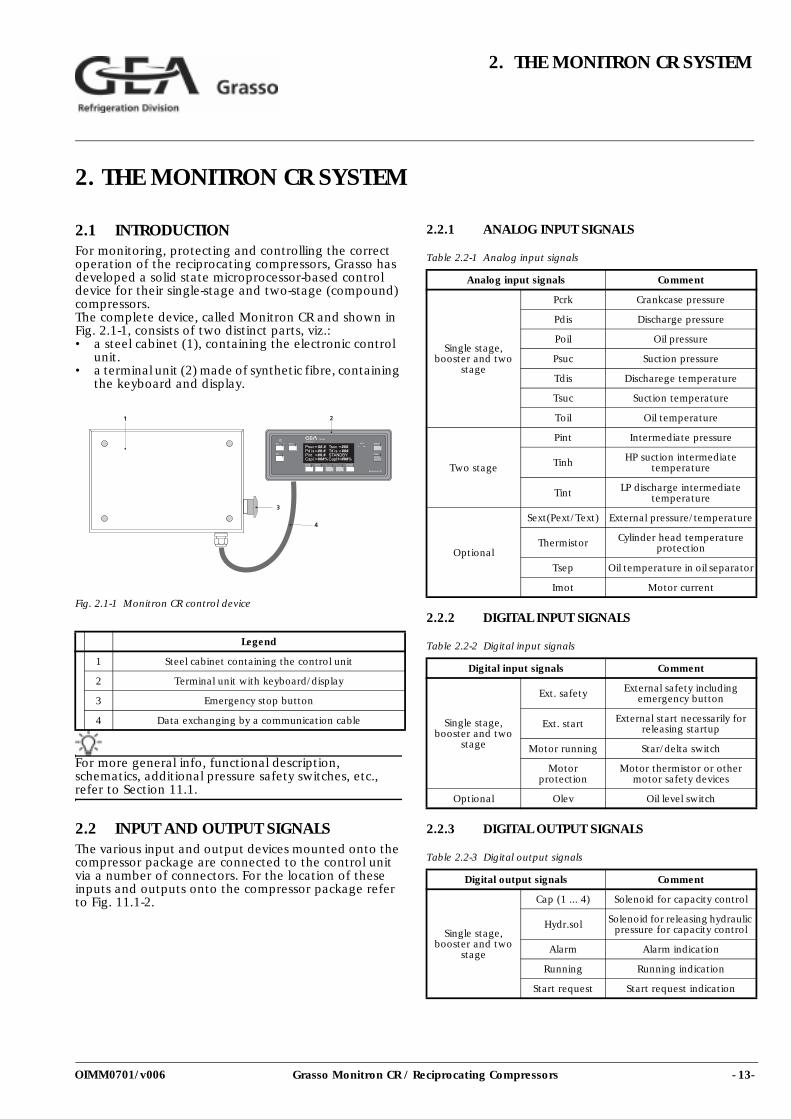
2.1 INTRODUCTIONFor monitoring, protecting and controlling the correct operation of the reciprocating compressors, Grasso has developed a solid state microprocessor-based control device for their single-stage and two-stage (compound) compressors. The complete device, called Monitron CR and shown in Fig. 2.1-1, consists of two distinct parts, viz.: • a steel cabinet (1), containing the electronic control
unit. • a terminal unit (2) made of synthetic fibre, containing
the keyboard and display.
Fig. 2.1-1 Monitron CR control device
For more general info, functional description, schematics, additional pressure safety switches, etc., refer to Section 11.1.
2.2 INPUT AND OUTPUT SIGNALSThe various input and output devices mounted onto the compressor package are connected to the control unit via a number of connectors. For the location of these inputs and outputs onto the compressor package refer to Fig. 11.1-2.
2.2.1 ANALOG INPUT SIGNALS
Table 2.2-1 Analog input signals
2.2.2 DIGITAL INPUT SIGNALS
Table 2.2-2 Digital input signals
2.2.3 DIGITAL OUTPUT SIGNALS
Table 2.2-3 Digital output signals
Legend
1 Steel cabinet containing the control unit
2 Terminal unit with keyboard/display
3 Emergency stop button
4 Data exchanging by a communication cable
Analog input signals Comment
Single stage, booster and two
stage
Pcrk Crankcase pressure
Pdis Discharge pressure
Poil Oil pressure
Psuc Suction pressure
Tdis Discharege temperature
Tsuc Suction temperature
Toil Oil temperature
Two stage
Pint Intermediate pressure
Tinh HP suction intermediate temperature
Tint LP discharge intermediate temperature
Optional
Sext(Pext/Text) External pressure/temperature
Thermistor Cylinder head temperature protection
Tsep Oil temperature in oil separator
Imot Motor current
Digital input signals Comment
Single stage, booster and two
stage
Ext. safety External safety including emergency button
Ext. start External start necessarily for releasing startup
Motor running Star/delta switch
Motor protection
Motor thermistor or other motor safety devices
Optional Olev Oil level switch
Digital output signals Comment
Single stage, booster and two
stage
Cap (1 ... 4) Solenoid for capacity control
Hydr.sol Solenoid for releasing hydraulic pressure for capacity control
Alarm Alarm indication
Running Running indication
Start request Start request indication
- 14- Grasso Monitron CR / Reciprocating Compressors
2. THE MONITRON CR SYSTEM
OIMM0701/v006
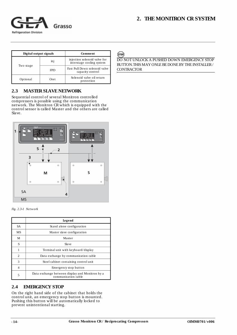
2.3 MASTER SLAVE NETWORKSequential control of several Monitron controlled compressors is possible using the communication network. The Monitron CR which is equipped with the control sensor is called Master and the others are called Slave.
Fig. 2.3-1 Network
2.4 EMERGENCY STOPOn the right hand side of the cabinet that holds the control unit, an emergency stop button is mounted. Pushing this button will be automatically locked to prevent unintentional starting.
DO NOT UNLOCK A PUSHED DOWN EMERGENCY STOP BUTTON.THIS MAY ONLE BE DONE BY THE INSTALLER / CONTRACTOR
Two stage
inj injection solenoid valve for interstage cooling system
FPD Fast Pull Down solenoid valve capacity control
Optional Oret Solenoid valve oil return protection
Legend
SA Stand alone configuration
MS Master slave configuration
M Master
S Slave
1 Terminal unit with keyboard/display
2 Data exchange by communication cable
3 Steel cabinet containing control unit
4 Emergency stop button
5 Data exchange between display and Monitron by a communication cable
Digital output signals Comment
- 15-Grasso Monitron CR / Reciprocating Compressors
3. STEP BY STEP OPERATION
OIMM0701/v006
3. STEP BY STEP OPERATION
Refer also to Section 9.1
3.1 KEYBOARD OPERATION
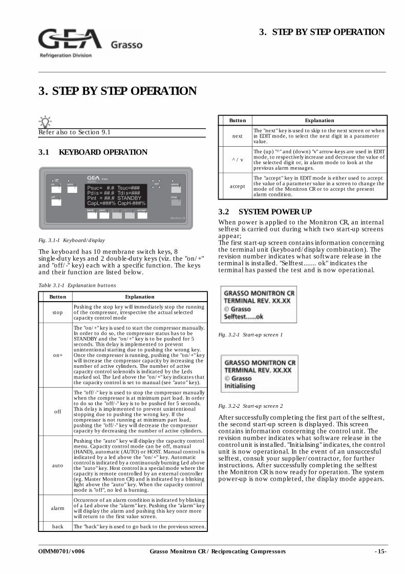
Fig. 3.1-1 Keyboard/display
The keyboard has 10 membrane switch keys, 8 single-duty keys and 2 double-duty keys (viz. the "on/+" and "off/-" key) each with a specific function. The keys and their function are listed below.
Table 3.1-1 Explanation buttons
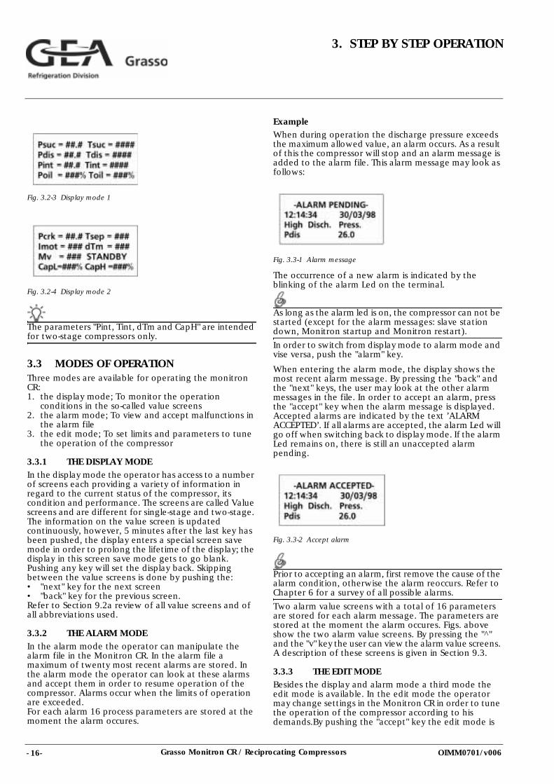
3.2 SYSTEM POWER UPWhen power is applied to the Monitron CR, an internal selftest is carried out during which two start-up screens appear;The first start-up screen contains information concerning the terminal unit (keyboard/display combination). The revision number indicates what software release in the terminal is installed. "Selftest....... ok" indicates the terminal has passed the test and is now operational.
Fig. 3.2-1 Start-up screen 1
Fig. 3.2-2 Start-up screen 2
After successfully completing the first part of the selftest, the second start-up screen is displayed. This screen contains information concerning the control unit. The revision number indicates what software release in the control unit is installed. "Initialising" indicates, the control unit is now operational. In the event of an unsuccesful selftest, consult your supplier/contractor, for further instructions. After successfully completing the selftest the Monitron CR is now ready for operation. The system power-up is now completed, the display mode appears.
Button Explanation
stopPushing the stop key will immediately stop the running of the compressor, irrespective the actual selected capacity control mode
on+
The "on/+" key is used to start the compressor manually. In order to do so, the compressor status has to be STANDBY and the "on/+" key is to be pushed for 5 seconds. This delay is implemented to prevent unintentional starting due to pushing the wrong key. Once the compressor is running, pushing the "on/+" key will increase the compressor capacity by increasing the number of active cylinders. The number of active capacity control solenoids is indicated by the Leds marked sol. The Led above the "on/+" key indicates that the capacity control is set to manual (see "auto" key).
off
The "off/-" key is used to stop the compressor manually when the compressor is at minimum part load. In order to do so the "off/-" key is to be pushed for 5 seconds. This delay is implemented to prevent unintentional stopping due to pushing the wrong key. If the compressor is not running at minimum part load, pushing the "off/-" key will decrease the compressor capacity by decreasing the number of active cylinders.
auto
Pushing the "auto" key will display the capacity control menu. Capacity control mode can be off, manual (HAND), automatic (AUTO) or HOST. Manual control is indicated by a led above the "on/+" key. Automatic control is indicated by a continuously burning Led above the "auto" key. Host control is a special mode where the capacity is remote controlled by an external controller (eg. Master Monitron CR) and is indicated by a blinking light above the "auto" key. When the capacity control mode is "off", no led is burning.
alarm
Occurence of an alarm condition is indicated by blinking of a Led above the "alarm" key. Pushing the "alarm" key will display the alarm and pushing this key once more will return to the first value screen.
back The "back" key is used to go back to the previous screen.
nextThe "next" key is used to skip to the next screen or when in EDIT mode, to select the next digit in a parameter value.
^ / v
The (up) "^" and (down) "v" arrow-keys are used in EDIT mode, to respectively increase and decrease the value of the selected digit or, in alarm mode to look at the previous alarm messages.
accept
The "accept" key in EDIT mode is either used to accept the value of a parameter value in a screen to change the mode of the Monitron CR or to accept the present alarm condition.
Button Explanation
- 16- Grasso Monitron CR / Reciprocating Compressors
3. STEP BY STEP OPERATION
OIMM0701/v006
Fig. 3.2-3 Display mode 1
Fig. 3.2-4 Display mode 2
The parameters "Pint, Tint, dTm and CapH" are intended for two-stage compressors only.
3.3 MODES OF OPERATIONThree modes are available for operating the monitron CR:1. the display mode; To monitor the operation
conditions in the so-called value screens2. the alarm mode; To view and accept malfunctions in
the alarm file3. the edit mode; To set limits and parameters to tune
the operation of the compressor
3.3.1 THE DISPLAY MODEIn the display mode the operator has access to a number of screens each providing a variety of information in regard to the current status of the compressor, its condition and performance. The screens are called Value screens and are different for single-stage and two-stage. The information on the value screen is updated continuously, however, 5 minutes after the last key has been pushed, the display enters a special screen save mode in order to prolong the lifetime of the display; the display in this screen save mode gets to go blank. Pushing any key will set the display back. Skipping between the value screens is done by pushing the:• "next" key for the next screen• "back" key for the previous screen.Refer to Section 9.2a review of all value screens and of all abbreviations used.
3.3.2 THE ALARM MODEIn the alarm mode the operator can manipulate the alarm file in the Monitron CR. In the alarm file a maximum of twenty most recent alarms are stored. In the alarm mode the operator can look at these alarms and accept them in order to resume operation of the compressor. Alarms occur when the limits of operation are exceeded.For each alarm 16 process parameters are stored at the moment the alarm occures.
ExampleWhen during operation the discharge pressure exceeds the maximum allowed value, an alarm occurs. As a result of this the compressor will stop and an alarm message is added to the alarm file. This alarm message may look as follows:
Fig. 3.3-1 Alarm message
The occurrence of a new alarm is indicated by the blinking of the alarm Led on the terminal.
As long as the alarm led is on, the compressor can not be started (except for the alarm messages: slave station down, Monitron startup and Monitron restart).
In order to switch from display mode to alarm mode and vise versa, push the "alarm" key.
When entering the alarm mode, the display shows the most recent alarm message. By pressing the "back" and the "next" keys, the user may look at the other alarm messages in the file. In order to accept an alarm, press the "accept" key when the alarm message is displayed. Accepted alarms are indicated by the text ’ALARM ACCEPTED’. If all alarms are accepted, the alarm Led will go off when switching back to display mode. If the alarm Led remains on, there is still an unaccepted alarm pending.
Fig. 3.3-2 Accept alarm
Prior to accepting an alarm, first remove the cause of the alarm condition, otherwise the alarm reoccurs. Refer to Chapter 6 for a survey of all possible alarms.
Two alarm value screens with a total of 16 parameters are stored for each alarm message. The parameters are stored at the moment the alarm occures. Figs. above show the two alarm value screens. By pressing the "^" and the "v" key the user can view the alarm value screens. A description of these screens is given in Section 9.3.
3.3.3 THE EDIT MODEBesides the display and alarm mode a third mode the edit mode is available. In the edit mode the operator may change settings in the Monitron CR in order to tune the operation of the compressor according to his demands.By pushing the "accept" key the edit mode is
- 17-Grasso Monitron CR / Reciprocating Compressors
3. STEP BY STEP OPERATION
OIMM0701/v006
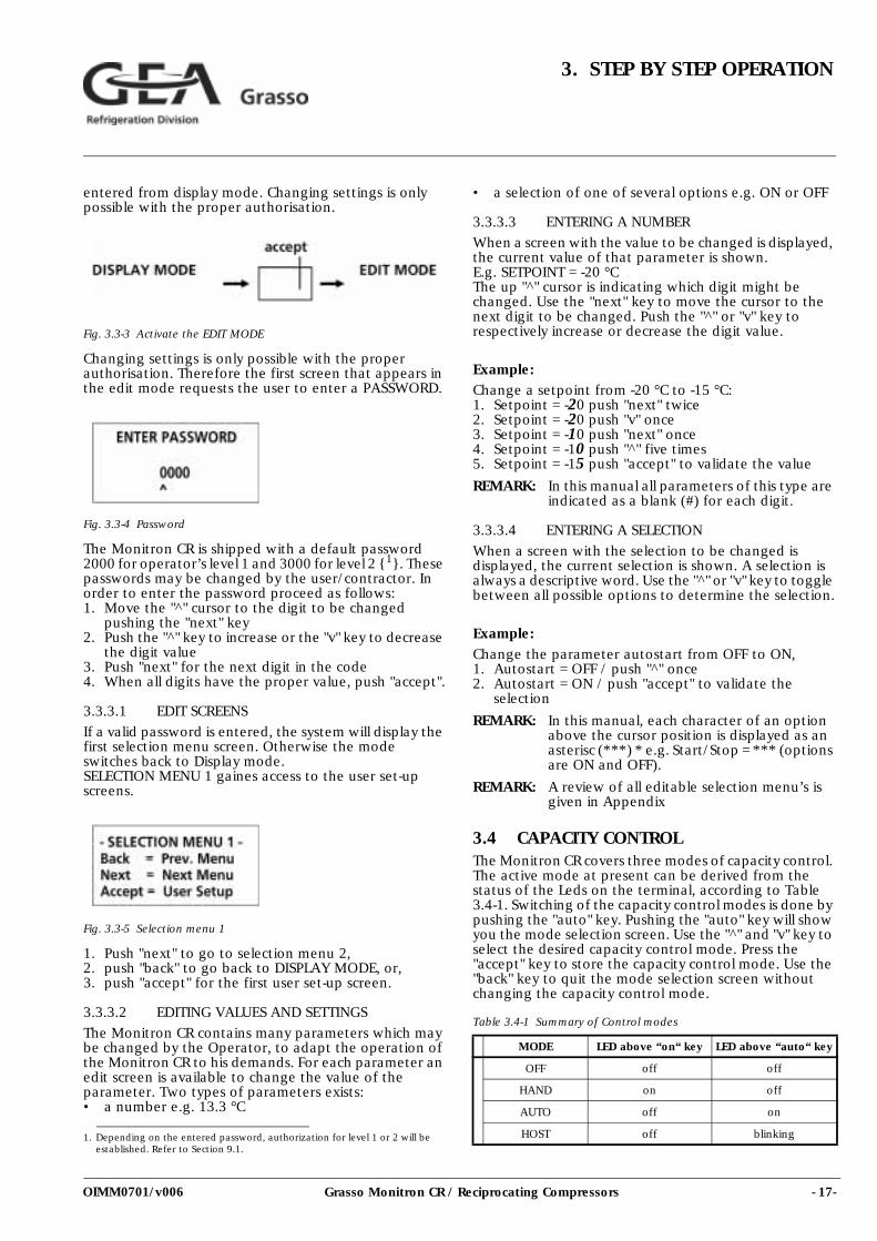
entered from display mode. Changing settings is only possible with the proper authorisation.
Fig. 3.3-3 Activate the EDIT MODE
Changing settings is only possible with the proper authorisation. Therefore the first screen that appears in the edit mode requests the user to enter a PASSWORD.
Fig. 3.3-4 Password
The Monitron CR is shipped with a default password 2000 for operator’s level 1 and 3000 for level 2 {1}. These passwords may be changed by the user/contractor. In order to enter the password proceed as follows: 1. Move the "^" cursor to the digit to be changed
pushing the "next" key2. Push the "^" key to increase or the "v" key to decrease
the digit value3. Push "next" for the next digit in the code4. When all digits have the proper value, push "accept".
3.3.3.1 EDIT SCREENS
If a valid password is entered, the system will display the first selection menu screen. Otherwise the mode switches back to Display mode. SELECTION MENU 1 gaines access to the user set-up screens.
Fig. 3.3-5 Selection menu 1
1. Push "next" to go to selection menu 2,2. push "back" to go back to DISPLAY MODE, or,3. push "accept" for the first user set-up screen.
3.3.3.2 EDITING VALUES AND SETTINGS
The Monitron CR contains many parameters which may be changed by the Operator, to adapt the operation of the Monitron CR to his demands. For each parameter an edit screen is available to change the value of the parameter. Two types of parameters exists:• a number e.g. 13.3 °C
• a selection of one of several options e.g. ON or OFF
3.3.3.3 ENTERING A NUMBER
When a screen with the value to be changed is displayed, the current value of that parameter is shown.E.g. SETPOINT = -20 °CThe up "^" cursor is indicating which digit might be changed. Use the "next" key to move the cursor to the next digit to be changed. Push the "^" or "v" key to respectively increase or decrease the digit value.
Example:Change a setpoint from -20 °C to -15 °C:1. Setpoint = -20 push "next" twice2. Setpoint = -20 push "v" once3. Setpoint = -10 push "next" once4. Setpoint = -10 push "^" five times5. Setpoint = -15 push "accept" to validate the value
REMARK: In this manual all parameters of this type are indicated as a blank (#) for each digit.
3.3.3.4 ENTERING A SELECTION
When a screen with the selection to be changed is displayed, the current selection is shown. A selection is always a descriptive word. Use the "^" or "v" key to toggle between all possible options to determine the selection.
Example:
Change the parameter autostart from OFF to ON,1. Autostart = OFF / push "^" once2. Autostart = ON / push "accept" to validate the
selection
REMARK: In this manual, each character of an option above the cursor position is displayed as an asterisc (***) * e.g. Start/Stop = *** (options are ON and OFF).
REMARK: A review of all editable selection menu’s is given in Appendix
3.4 CAPACITY CONTROLThe Monitron CR covers three modes of capacity control. The active mode at present can be derived from the status of the Leds on the terminal, according to Table 3.4-1. Switching of the capacity control modes is done by pushing the "auto" key. Pushing the "auto" key will show you the mode selection screen. Use the "^" and "v" key to select the desired capacity control mode. Press the "accept" key to store the capacity control mode. Use the "back" key to quit the mode selection screen without changing the capacity control mode.
Table 3.4-1 Summary of Control modes
1. Depending on the entered password, authorization for level 1 or 2 will be established. Refer to Section 9.1.
MODE LED above “on“ key LED above “auto“ key
OFF off off
HAND on off
AUTO off on
HOST off blinking
- 18- Grasso Monitron CR / Reciprocating Compressors
3. STEP BY STEP OPERATION
OIMM0701/v006
CAPACITY LIMITATION: The Monitron CR is equipped with a capacity limitation control loop. When this control loop is activated due to high motor current or discharge pressure no capacity increase is possible. In case of high discharge temperature no capacity decrease is possible.
3.4.1 CAPACITY CONTROL IN HAND MODEIn HAND mode, the compressor capacity is to be set manually. In order to do so, the terminal is equipped with two keys, the "on/+" key for starting and increasing capacity, the "off/-" key for decreasing capacity and stopping.
STARTING MANUALLY
The compressor is started by pushing the "on/+" key for approx. 5 seconds. The compressor will switch from STANDBY to STARTING and enters the start-up routine as described in Section 4.5. When no failures occur the compressor will switch to RUNNING and capacity control is possible.
INCREASING CAPACITY
Compressor capacity may be increased by pressing the "on/+" key once. The Monitron CR determines the next available higher capacity. The Leds of the energized solenoids will light up.
DECREASING CAPACITYCompressor capacity may be decreased by pressing the "off/-" key once. The Monitron CR determines the next available lower capacity. The Leds of the de-energized solenoids will go off.
STOPPING MANUALLYThe compressor may be stopped in several ways. The normal stop procedure is pushing the "off/-" key until the compressor is at min. part load and then either holding the "off/-" key for 5 seconds, or pushing the "stop" key.
3.4.2 CAPACITY CONTROL IN AUTO MODE
In mode AUTO, the compressor capacity is set automatically via the control loop in the Monitron CR. Based on the difference between required pressure (SETPOINT) and measured pressure (MV), the control loop calculates the required compressor capacity.
STARTING/STOPPINGStarting and stopping the compressor in mode AUTO is determined by the status of the start/stop parameter (ST/ST). If this parameter is set to ON (displayed in value screen 3, the compressor will start and stop automatically. The compressor however, must be start-up and shutdown manually, if the parameter is set to OFF.
3.4.3 CAPACITY CONTROL IN HOST MODEIn mode HOST, the compressor capacity is set automatically by a remote system, via the communication network. Refer to for more detailed information.
- 19-Grasso Monitron CR / Reciprocating Compressors
4. START, STOP AND RESTARTPROCEDURES
OIMM0701/v006
4. START, STOP AND RESTART PROCEDURES
Refer also to Section 9.1
4.1 GENERAL START PROCEDURE GRASSO 12E, GRASSO 12 AND GRASSO 10
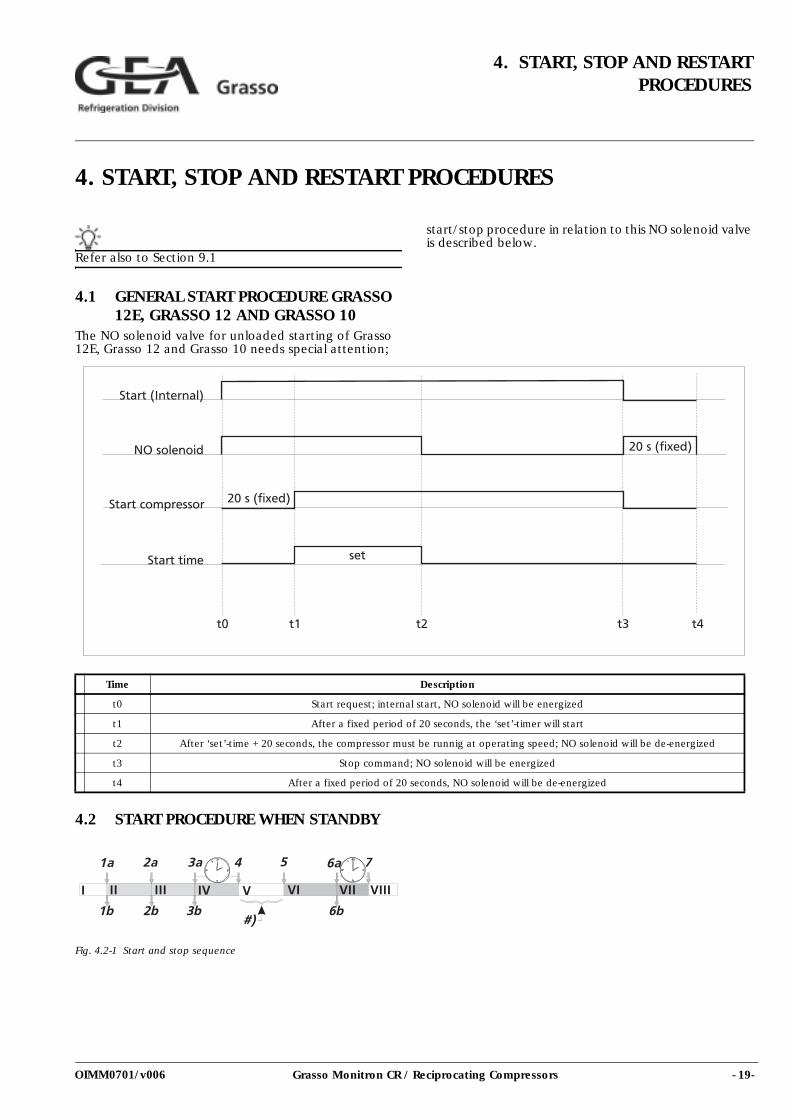
The NO solenoid valve for unloaded starting of Grasso 12E, Grasso 12 and Grasso 10 needs special attention;
start/stop procedure in relation to this NO solenoid valve is described below.
4.2 START PROCEDURE WHEN STANDBY
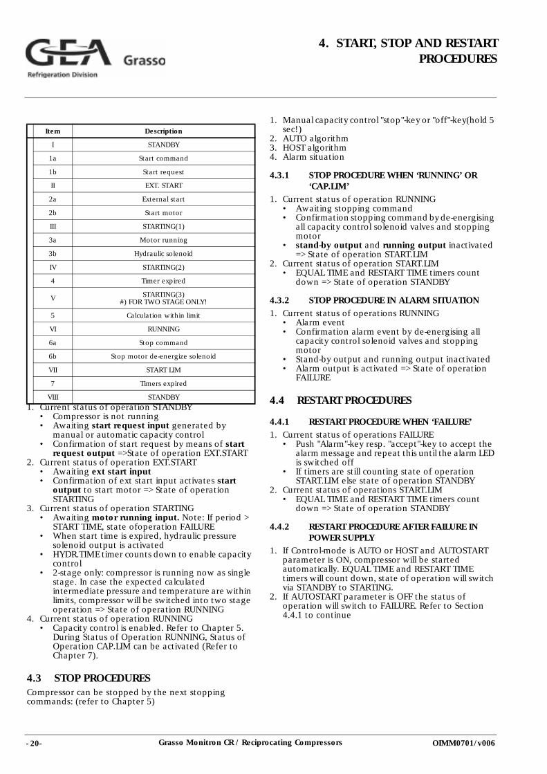
Fig. 4.2-1 Start and stop sequence
Time Description
t0 Start request; internal start, NO solenoid will be energized
t1 After a fixed period of 20 seconds, the ‘set’-timer will start
t2 After ‘set’-time + 20 seconds, the compressor must be runnig at operating speed; NO solenoid will be de-energized
t3 Stop command; NO solenoid will be energized
t4 After a fixed period of 20 seconds, NO solenoid will be de-energized
- 20- Grasso Monitron CR / Reciprocating Compressors
4. START, STOP AND RESTARTPROCEDURES
OIMM0701/v006
1. Current status of operation STANDBY• Compressor is not running• Awaiting start request input generated by
manual or automatic capacity control • Confirmation of start request by means of start
request output =>State of operation EXT.START2. Current status of operation EXT.START
• Awaiting ext start input• Confirmation of ext start input activates start
output to start motor => State of operation STARTING
3. Current status of operation STARTING• Awaiting motor running input. Note: If period >
START TIME, state ofoperation FAILURE• When start time is expired, hydraulic pressure
solenoid output is activated • HYDR.TIME timer counts down to enable capacity
control• 2-stage only: compressor is running now as single
stage. In case the expected calculated intermediate pressure and temperature are within limits, compressor will be switched into two stage operation => State of operation RUNNING
4. Current status of operation RUNNING• Capacity control is enabled. Refer to Chapter 5.
During Status of Operation RUNNING, Status of Operation CAP.LIM can be activated (Refer to Chapter 7).
4.3 STOP PROCEDURESCompressor can be stopped by the next stopping commands: (refer to Chapter 5)
1. Manual capacity control "stop"-key or "off"-key(hold 5 sec!)
2. AUTO algorithm3. HOST algorithm4. Alarm situation
4.3.1 STOP PROCEDURE WHEN ‘RUNNING’ OR ‘CAP.LIM’
1. Current status of operation RUNNING• Awaiting stopping command• Confirmation stopping command by de-energising
all capacity control solenoid valves and stopping motor
• stand-by output and running output inactivated => State of operation START.LIM
2. Current status of operation START.LIM• EQUAL TIME and RESTART TIME timers count
down => State of operation STANDBY
4.3.2 STOP PROCEDURE IN ALARM SITUATION
1. Current status of operations RUNNING• Alarm event• Confirmation alarm event by de-energising all
capacity control solenoid valves and stopping motor
• Stand-by output and running output inactivated • Alarm output is activated => State of operation
FAILURE
4.4 RESTART PROCEDURES
4.4.1 RESTART PROCEDURE WHEN ‘FAILURE’1. Current status of operations FAILURE
• Push "Alarm"-key resp. "accept"-key to accept the alarm message and repeat this until the alarm LED is switched off
• If timers are still counting state of operation START.LIM else state of operation STANDBY
2. Current status of operations START.LIM• EQUAL TIME and RESTART TIME timers count
down => State of operation STANDBY
4.4.2 RESTART PROCEDURE AFTER FAILURE IN POWER SUPPLY
1. If Control-mode is AUTO or HOST and AUTOSTART parameter is ON, compressor will be started automatically. EQUAL TIME and RESTART TIME timers will count down, state of operation will switch via STANDBY to STARTING.
2. If AUTOSTART parameter is OFF the status of operation will switch to FAILURE. Refer to Section 4.4.1 to continue
Item Description
I STANDBY
1a Start command
1b Start request
II EXT. START
2a External start
2b Start motor
III STARTING(1)
3a Motor running
3b Hydraulic solenoid
IV STARTING(2)
4 Timer expired
V STARTING(3)#) FOR TWO STAGE ONLY!
5 Calculation within limit
VI RUNNING
6a Stop command
6b Stop motor de-energize solenoid
VII START LIM
7 Timers expired
VIII STANDBY
- 21-Grasso Monitron CR / Reciprocating Compressors
4. START, STOP AND RESTARTPROCEDURES
OIMM0701/v006
4.5 STATES OF OPERATION
Survey ’Value screens’ refer to Section 9.2.
State of operation dependant on settings and measured values.
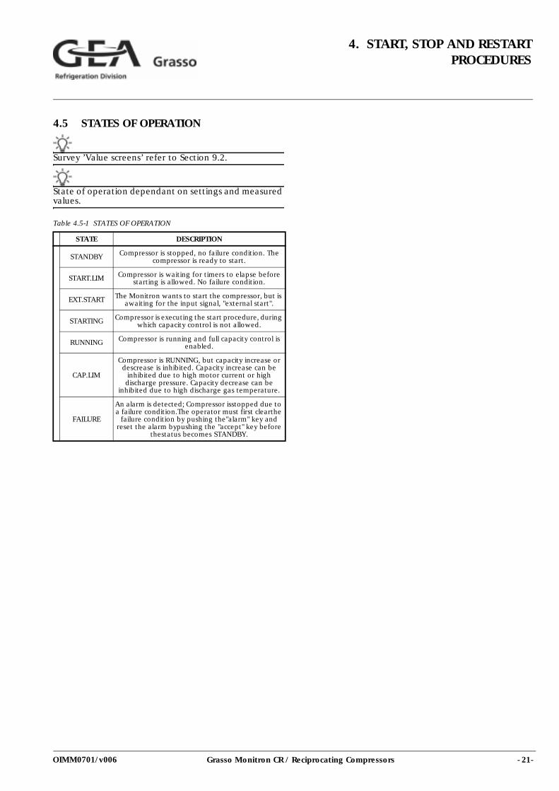
Table 4.5-1 STATES OF OPERATION
STATE DESCRIPTION
STANDBY Compressor is stopped, no failure condition. The compressor is ready to start.
START.LIM Compressor is waiting for timers to elapse before starting is allowed. No failure condition.
EXT.START The Monitron wants to start the compressor, but is awaiting for the input signal, "external start".
STARTING Compressor is executing the start procedure, during which capacity control is not allowed.
RUNNING Compressor is running and full capacity control is enabled.
CAP.LIM
Compressor is RUNNING, but capacity increase or descrease is inhibited. Capacity increase can be
inhibited due to high motor current or high discharge pressure. Capacity decrease can be
inhibited due to high discharge gas temperature.
FAILURE
An alarm is detected; Compressor isstopped due to a failure condition.The operator must first clearthe
failure condition by pushing the"alarm" key and reset the alarm bypushing the "accept" key before
thestatus becomes STANDBY.
- 22- Grasso Monitron CR / Reciprocating Compressors
4. START, STOP AND RESTARTPROCEDURES
OIMM0701/v006
- 23-Grasso Monitron CR / Reciprocating Compressors
5. CAPACITY CONTROL MODES
OIMM0701/v006
5. CAPACITY CONTROL MODES
5.1 CAPACITY CONTROL MODES• Selection of capacity control mode refer to Section
3.4.• Pre-condition: State of operation RUNNING (refer to
Section 4.5).• An explanation of the operation and description of
the capacity control system refer to Compressor Manual.
• The Monitron is able to select the right capacity step, depending on measured values, compressor limits and parameter settings. Capacity control actions are start compressor, increasing/decreasing capacity, stop compressor.
5.2 MANUAL MODE1. LED above "on/+"-key is on.2. State of operation is STANDBY.3. Start compressor hold "on/+"-key for 5 seconds (start
up procedures will be triggered, refer to Section 4.2).4. State of operation is RUNNING.5. Push "on/+"-key to increase capacity.6. Push "off/-"-key to decrease capacity.7. Stop compressor push "stop"-key or hold "off/-"-key
for 5 seconds.8. State of operation via START LIM to STANDBY.
5.3 AUTOMATIC MODE FOR STAND-ALONE COMPRESSOR
1. LED above the "auto"-key is on2. Manual start not possible.3. Automatic start/stop only possible if START/STOP
parameter is ON.
REMARK: If START/STOP=OFF and AUTO-mode is required the compressor has to be started in MANUAL-mode and switched to AUTO-mode.
4. Manual stop push "stop"-key. If compressor is stopped manually in AUTOmode, the MANUAL-mode will be activated.
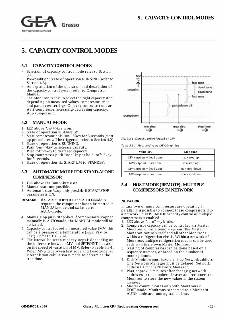
5. Capacity control based on measured value (MV) this can be a presure or a temperature (Psuc, Pext or Text). Refer to Fig. 5.3-1.
6. The interval between capacity steps is depending on the difference between MV and SETPOINT, but also on the speed of variation of MV. Refer to Table 5.3-1. When MV is inbetween Fast zone and Dead zone, an interpolation calculation is made to determine the step time.
Fig. 5.3-1 Capacity control based on MV
Table 5.3-1 Measured value (MV)-Step time
5.4 HOST MODE (REMOTE), MULTIPLE COMPRESSORS IN NETWORK
NETWORKIn case two or more compressors are operating in parallel, it is possible to connect these compressors into a network. In HOST MODE capacity control of multiple compressors is enabled. 1. LED above "auto"-key blinks. 2. Compressor capacity can be controlled via Master
Monitron, or via a remote system. The Master Monitron controls itself and all other Monitrons within a refrigeration circuit. Within a network of Monitrons multiple refrigeration circuits can be used, each with there own Master Monitron.
3. Starting of compressors can be done based on a sequence number, or based on the number of running hours.
4. Each Monitron must have a unique Network address. One Network Manager must be defined. Network address 01 means Network Manager.
5. Wait approx. 2 minutes after changing network addresses or the number of slaves and reconnect the Monitron to store the new values in the system memory.
6. Master communicates only with Monitrons in HOST-mode. Monitrons connected to a Master in AUTO-mode are running stand-alone.
Value MV Step time
MV>setpoint + dead zone max step up
MV>setpoint + fast zone min step up
MV<setpoint + dead zone max step down
MV<setpoint + fast zone min step down
- 24- Grasso Monitron CR / Reciprocating Compressors
5. CAPACITY CONTROL MODES
OIMM0701/v006
7. Never switch a Master from HOST to HAND or AUTO unless all slaves stopped or in HAND or in AUTO-mode. If a Slave is in HOST-mode and the master is not, the slave will be uncontrolled.
8. When a Slave is switched from HAND or AUTO to HOST-mode, the Master will add it to the list of available compressors.
9. MV=f(SETPOINT, ZONE) equal to AUTO-mode (refer Fig. 5.3-1)
INCREASING AND DECREASING CAPACITY
The following procedures are used to determinehow to increase or decrease capacity:1. More capacity needed:Check for a running
compressor which is not at full-load and not limited by a high motor current or by high discharge pressure. If found this compressor is stepped up. If not found, a compressor should be started.
2. Less capacity needed: If two or more compressors are running the two compressors last started are observed. The last started compressor is stepped down unless it is at minimum capacity. If the last compressors is at its minimum and the other compressor = 100% then the other compressor will step down. When the other compressor 100% the last compressor will stop.
3. An overview of the control parameters and additional functionality is given in Section 5.5.
5.5 AUTO AND HOST-MODE CONTROL PARAMETERS
Refer also Fig. 5.3-1
5.5.1 AUTO AND HOST
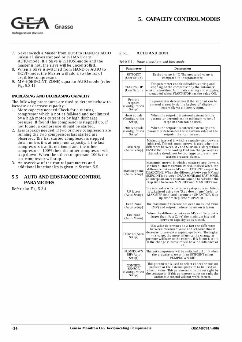
Table 5.5-1 Parameters; Auto and Host mode
Parameter Description
SETPOINT (User Setup)
Desired value in °C. The measured value is compared to this parameter.
START/STOP (User Setup)
This parameter enables/disables starting and stopping of the compressor by the automatic
control algorithm. Automatic starting and stopping is enabled when START/STOP has the value ON.
Remote setpoint
(Configuration Setup)
This parameter determines if the setpoint can be entered manually via the keyboard/ display or
externally via a 4-20mA input.
4mA equals (Configuration
Setup)
When the setpoint is entered externally, this parameter determines the minimum value of
setpoint than can be used.
20mA equals (Configuration
Setup)
When the setpoint is entered externally, this parameter determines the maximum value of the
setpoint that can be used.
Min Step (Auto Setup)
Minimum interval in which a capacity step down is inhibited. This minimum interval is used when the
difference between MV and SETPOINT is larger than FAST ZONE. If the cooling load can change very fast this value should not be too large to prevent low
suction pressure alarms.
Max Step time (Auto Setup)
Maximum interval in which a capacity step down is inhibited. This maximum interval is used when the difference between MV and SETPOINT is equal to
DEAD ZONE. When the difference between MV and SETPOINT is between DEAD ZONE and FAST ZONE, an interpolation calculation is made to calculate the Step time between MIN STEP and MAX STEP time.
UP factor (Auto Setup)
The interval in which a capacity step up is inhibited, is calculated using the "Step down time" (refer to MAX STEP time) and parameter UP FACTOR. Step
up time = step time * UPFACTOR
Dead Zone (Auto Setup)
The maximum difference between measured value (MV) and setpoint where no action is taken
Fast zone (Auto Menu)
When the difference between MV and Setpoint is larger than ’Fast Zone" the minimum interval
between capacity steps is used.
D-factor (Auto Setup)
This value determines how fast the difference between measured value and setpoint should
decrease to prevent stepping up/down. The higher this value, the more influence the change in
pressure will have to the control. If D-factor is set to 0 the change in pressure will have no influence at
all.
PUMPDOWN DIF (Auto
Setup)
The last compressor will be switched off only when the pressure is lower than SETPOINT minus
PUMPDOWN DIF.
CONTROL SENSOR
(Configuration Setup)
This parameter is used to select either the suction pressure or the external pressure to be used as
control value. This parameter must be set right by the contractor. If this parameter is not set right the
automatic control will not work correct.
- 25-Grasso Monitron CR / Reciprocating Compressors
5. CAPACITY CONTROL MODES
OIMM0701/v006
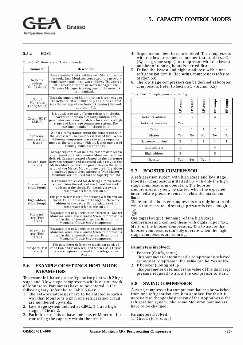
5.5.2 HOST
Table 5.5-2 Parameters; Host mode only
5.6 EXAMPLE OF SETTINGS HOST MODE PARAMETERS
This example is based on a refrigeration plant with 2 high stage and 3 low stage compressors within one network of Monitrons. Parameters have to be entered in the following way (refer also to Table 5.6-1):1. The network addresses have to be entered in such a
way that Monitrons within one refrigeration circuit are numbered upwards.
2. Low stage system defined as CIRCUIT 1 and high stage as Circuit 2.
3. Each circuit needs to have one master Monitron for controlling the capacity within the circuit
4. Sequence numbers have to entered. The compressors with the lowest sequence number is started first. Or (By using same seqnr) to compressor with the lowest number of running hours is started first.
5. Define the lowest and highest address within one refrigeration circuit. (for swing compressors refer to Section 5.8.
6. The low stage compressors can be defined as booster compressors (refer to Section 5.7Section 5.5)
Table 5.6-1 Example parameter settings
5.7 BOOSTER COMPRESSORA refrigeration system with high stage and low stage (booster) compressors is started up with only the high stage compressors in operation. The booster compressors may only be started when the expected intermediate pressure remains below the maximum limit. Therefore the booster compressors can only be started when the measured discharge pressure is low enough.
Use digital output "Running" of the high stage compressors and connect these with digital input "Ext. Start" of the booster compressors. This to assure that booster compressors can only operate when the high stage compressors are running.
Parameters involved:1. Booster (Config setup)
This parameter determines if a compressor is selected as booster compressor. The value can be Yes or No.
2. P booster (Config setup)This parameter determines the value of the discharge pressure required to allow the compressor to start.
5.8 SWING COMPRESSORA swing compressor is a compressor that can be switched from one refrigeration circuit to another. For this it is necessary to change the position of the stop valves in the refrigeration system. Also some Monitron parameters have to be changed.
Parameters involved:1. Circuit (Host setup)
Parameter Description
Network address
(Config Setup)
This is a number that identifies each Monitron in the network. Each Monitron connected to a network
should have a unique network address. The address 01 is reserved for the network manager. The
Network Manager is taking care of the network communication.
Nbr of Monitrons
(Config Setup)
This is the number of Monitrons that is connected to the network. This number only has to be entered into the settings of the Network master (Network
address = 01).
Circuit (HOST SETUP)
It is possible to use different refrigerant circuits, each with there own capacity control. This
parameter can be used to define for instance a high stage and low stage compressor system. The
maximum number of circuits is 11.
Sequence number (Host
Setup)
Within a refrigeration circuit the compressor with the lowest sequence number is started first. When
different compressors have the same sequence number, the compressor with the lowest number of
running hours is started first.
Master (Host Setup)
For capacity control of multiple compressors within a refrigeration circuit a master Monitron has to be defined. Capacity control is based on the difference between Setpoint and measured value (MV) of the Master Monitron.Also the parameters in the Auto setup of the Master Monitron are used. The above
mentioned parameters entered in "Non Master" Monitrons are not used for the capacity control.
Low address (Host Setup)
This parameter is used for defining a refrigeration circuit. Enter the value of the lowest Network
address in the circuit. For defining a swing compressor refer to Section 5.6
High address (Host Setup)
This parameters is used for defining a refrigeration circuit. Enter the value of the highest Network
address of the circuit. For defining a swing compressor refer to Section 5.6
Screw min step (Host
Setup)
This parameter only needs to be entered in a Master Monitron when also a Grasso Screw compressor is
used in the refrigeration system. Refer to the Manual of Grasso Screw compressor.
Screw max step (Host
Setup)
This parameter only needs to be entered in a Master Monitron when also a Grasso Screw compressor is
used in the refrigeration system. Refer to the Manual of Grasso Screw compressor.
Maxpart (Host Setup)
This parameter defines the maximum partload condition and is only required when also a Grasso
Screw compressor is used in the refrigeration system.
LP c
om
pr
LP c
om
pr
LP c
om
pr
HP
com
pr
HP
com
pr
Network address 1 3 3 4 5
Network manager Yes
Circuit 1 1 1 2 2
Master Yes No No No No
Sequence number 2 1 1 1 1
Low address 1 4
HIgh address 3 5
Booster Yes Yes Yes
- 26- Grasso Monitron CR / Reciprocating Compressors
5. CAPACITY CONTROL MODES
OIMM0701/v006
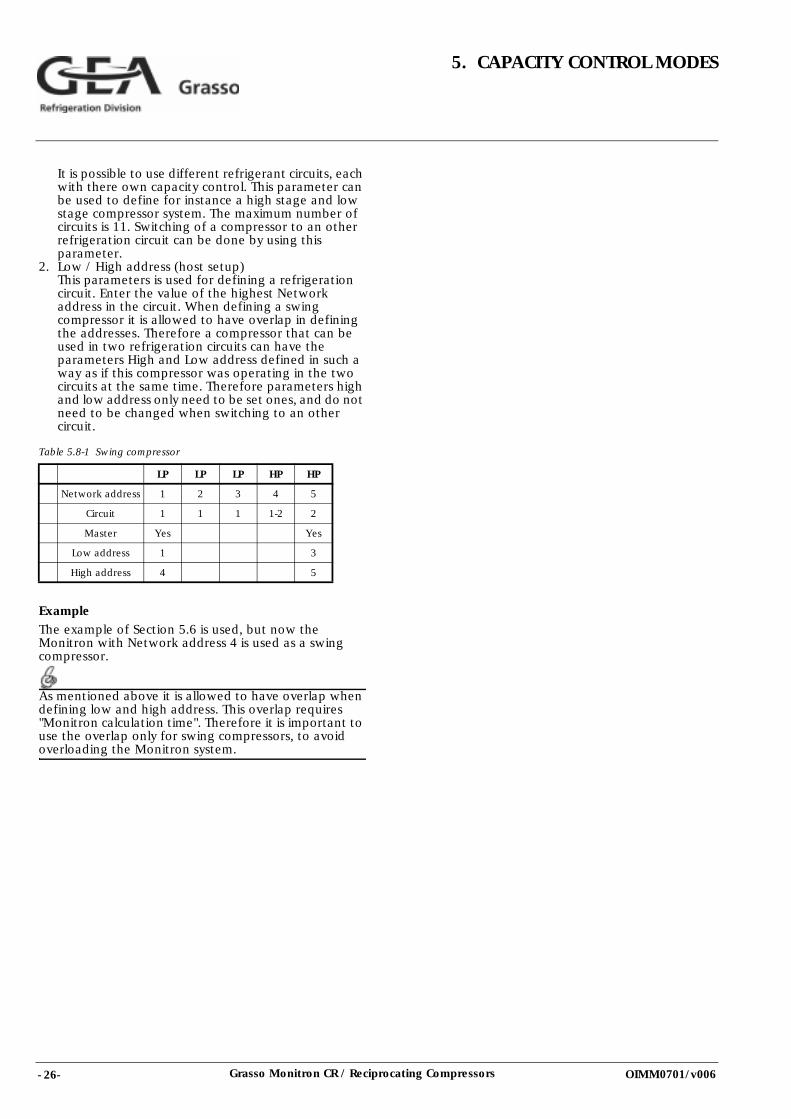
It is possible to use different refrigerant circuits, each with there own capacity control. This parameter can be used to define for instance a high stage and low stage compressor system. The maximum number of circuits is 11. Switching of a compressor to an other refrigeration circuit can be done by using this parameter.
2. Low / High address (host setup)This parameters is used for defining a refrigeration circuit. Enter the value of the highest Network address in the circuit. When defining a swing compressor it is allowed to have overlap in defining the addresses. Therefore a compressor that can be used in two refrigeration circuits can have the parameters High and Low address defined in such a way as if this compressor was operating in the two circuits at the same time. Therefore parameters high and low address only need to be set ones, and do not need to be changed when switching to an other circuit.
Table 5.8-1 Swing compressor
ExampleThe example of Section 5.6 is used, but now the Monitron with Network address 4 is used as a swing compressor.
As mentioned above it is allowed to have overlap when defining low and high address. This overlap requires "Monitron calculation time". Therefore it is important to use the overlap only for swing compressors, to avoid overloading the Monitron system.
LP LP LP HP HP
Network address 1 2 3 4 5
Circuit 1 1 1 1-2 2
Master Yes Yes
Low address 1 3
High address 4 5
- 27-Grasso Monitron CR / Reciprocating Compressors
6. ALARM MESSAGES
OIMM0701/v006
6. ALARM MESSAGES
6.1 ALARM MESSAGES
Pre-conditions: state of operation FAILURE. For description of state of operation refer to Section 4.5
6.1.1 DIGITAL INPUT ALARMS
A) Motor protection alarm
This condition is active when the motor protection input is interrupted. Normally this is done by the motor starter and protection circuit installed by the contractor. Alarm message MOTOR PROTECTION is stored in the alarm history file and the state of operation is FAILURE. Detected: in all states of operation.
B) External safeties alarm
The compressor will stop immediately after the external safeties input are interrupted. Normally this input is equip-ped with the emergency button. Other safety devices may be added in series for extra protection of the compressor unit. When this signal becomes active alarm message EXT. SAFETY ACTIVE is stored in the alarm history file and the state of operation is FAILURE. Detection: in all states of operation.
C) Motor running signal alarm
If the motor running indication disappears while the Monitron expects the motor to run, the alarm message NO MOTOR RUNNING (STARDEL OFF) is stored in the alarm history file and the state of operation is FAILURE. Activating the additional high pressure safety switch will also generate this alarm. Detection: RUNNING, CURR.LIM and STARTING.
6.1.2 EXCEEDING LIMITS ALARMS
A) Maximum motor current alarm
The measured motor current Imot is compared with a max. limit. If Imot is beyond this limit, alarm message "HIGH MOTOR AMP." is stored in the alarm history file and the state of operation is FAILURE. Detection: RUNNING, CURR.LIM and STARTING. Note: This condition should not be confused with the current limitation option in the capacity control, where capacity is reduced until Imot does not exeed the parameter Ilim.
B) Minimum motor current alarm
The measured motor current Imot is compared against a minimum limit. If Imot is lower than this limit, the alarm message Low Motor Amp. is stored in the alarm history file and the state of operation is FAILURE. Detection: RUNNING, CURR.LIM and STARTING. Note: If Imot limit is set to 00, motor current protection alarm is inhibited.
C) Thermistor protection alarm
The electric motor and cylinders may be equipped with a thermistor. This PTC device protects against high temperature. If the temperature arises above a certain level, alarm message TERM HIGH TEMPERATURE is stored in the alarm history file and the state of operation is FAILURE. Detection: in all states of operation.
D) Low suction pressure
The measured suction pressure Psuc is compared with a min. limit, entered by the contractor. If Psuc is less than this limit, alarm message "LOW SUCTION" is stored in the alarm history file and the state of operation is FAILURE. Detection: EXT.START, STARTING, RUNNING and CURR.LIM.
E) High discharge pressure
The measured discharge pressure Pdis is compared with a max. limit, entered by the contractor. If Pdis is beyond this limit, alarm message "HIGH DISCH. PRES." is stored in the alarm history file and the state of operation is FAILURE. Detection: EXT.START, STARTING, RUNNING and CURR.LIM.
F) High discharge temperature
The measured discharge temperature Tdis is compared with a maximum limit, entered by the contractor. If Tdis is beyond this limit, alarm message "HIGH DISCH. TEMP." is stored in the alarm history file and the state of operation is FAILURE. Detection: EXT.START, STARTING, RUNNING and CURR.LIM.
G) High oil temperature
The measured oil temperature Toil is compared with a max. limit, entered by the contractor. If Toil is beyond this limit, alarm message "HIGH OIL TEMP." is stored in the alarm history file and the state of operation is FAILURE. Detection: EXT.START, STARTING, RUNNING and CURR.LIM.
H) Low oil pressure
The measured oil pressure difference dOil is compared with a min. limit, entered by the contractor. If dOil is below this limit, alarm message "LOW OIL PRES" is stored in the alarm history file and the state of opeation is FAILURE. Detection: RUNNING, CURR.LIM and STARTING.
I) Low superheat at suction side (dTo)
The superheat of the suction gas is calculated from the measured suction pressure and temperature. The superheat is compared with a min. limit, entered by the contractor. If the superheat is below this limit for a while, alarm message "LOW SUPERHEAT" is stored in the alarm history file and the state of operation is FAILURE.
- 28- Grasso Monitron CR / Reciprocating Compressors
6. ALARM MESSAGES
OIMM0701/v006
Detection: STARTING, RUNNING and CURR.LIM.
REMARK: The testing of this condition is delayed for certain time after the state becomes STARTING. If this limit is set to zero (0), the low superheat alarm is inhibited.
J) High pressure difference
The difference between the measured discharge and suction pressure is compared with the maximum limit depending on compressor type. If the pressure difference is beyond this limit, alarm message "PRESS DIFF TOO HIGH" is stored in the alarm history file and the state of operation is FAILURE. Detection: STARTING, RUNNING and CURR.LIM.
K) High suction pressure
The measured suction pressure Psuc is compared with a max. limit, entered by the contractor. If Psuc is beyond this limit, alarm message "HIGH SUCTION" is stored in the alarm history file and state of operation is FAILURE. Detection: STARTING, RUNNING and CURR.LIM. Note: The testing of this condition is delayed for certain time after the state becomes STARTING.
6.1.3 ALARMS FOR TWO STAGE COMPRESSORS ONLY
A) High intermediate pressure
The measured suction pressure Pint is compared against a maximum limit. If Pint is beyond this limit, an alarm is generated, the message "HIGH INT. PRES." is stored in the alarm history file and the state is set to FAILURE. This alarm condition is tested in the states STARTING, RUNNING and CURR.LIM.
B) Low superheat at intermediate side (dTm)
The superheat of the intermediate gas is calculated from the measured intermediate pressure and temperature. The superheat is compared to a minimum limit. If the superheat is below this level for a certain time an alarm is generated, the message "LOW SUPERHEAT" is stored in the alarm history file and the state is set to FAILURE. This alarm condition is tested for in states STARTING, RUNNING & CURR.LIM. The testing of this condition is delayed for a certain time after the state becomes STARTING. Note: If this limit is set to 0, the low superheat alarm is inhibited.
C) High intermediate temperature (discharge LP)
The measured intermediate temperature at LP side Tint is compared with a maximum limit. If Tint is beyond this limit, an alarm is generated, the message "HIGH INT. TEMP." is stored in the alarm history file and state is set to FAILURE. This alarm condition is tested in all states.
- 29-Grasso Monitron CR / Reciprocating Compressors
7. CAPACITY LIMITING FUNCTIONS
OIMM0701/v006
7. CAPACITY LIMITING FUNCTIONS
7.1 MOTOR CURRENT LIMITATIONThe Monitron is equipped with a control function that not only makes the compressor step down in capacity, when the motor current is above a user programmable parameter, but also prevents that the capacity is increased, when it can be expected that the motor current will be too high after a step up in capacity.When the motor current limitation is activated the compressor status will become CAP.LIM.
Parameters involved:
1. ILIM (Configuration setup)When the motor current becomes above this value the capacity is stepped down.
2. MAX.IMOT (limits setup)When the motor current becomes above this value the compressor is stopped.
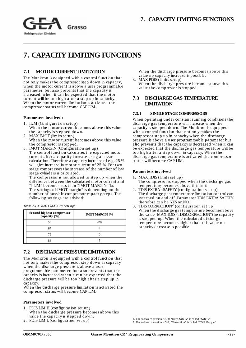
3. IMOT MARGIN (Configuration set up)The control function calculates the expected motor current after a capacity increase using a linear calculation. Therefore a capacity increase of e.g. 25 % will give increase in motor current of 25 %. For two stage compressors the increase of the number of low stage cylinders is calculated.The compressor is not allowed to step up when the difference between the calculated motor current and “I LIM” becomes less than “IMOT MARGIN” %.The settings of IMOT margin” is depending on the number of possible compressor capacity steps. The following settings are advised:
Table 7.1-1 IMOT MARGIN Settings
7.2 DISCHARGE PRESSURE LIMITATIONThe Monitron is equipped with a control function that not only makes the compressor step down in capacity when the discharge pressure is above a user programmable parameter, but also prevents that the capacity is increased when it can be expected that the discharge pressure will be too high after a step up in capacity.When the discharge pressure limitation is activated the compressor status will become CAP LIM.
Parameters involved1. PDIS LIM H (configuration set up)
When the discharge pressure becomes above this value the capacity is stepped down.
2. PDIS LIM L (configuration set up)
When the discharge pressure becomes above this value no capacity increase is possible.
3. MAX PDIS (limits setup)When the discharge pressure becomes above this value the compressor is stopped.
7.3 DISCHARGE GAS TEMPERATURE LIMITATION
7.3.1 SINGLE STAGE COMPRESSORSWhen operating under constant running conditions the discharge gas temperature will increase when the capacity is stepped down. The Monitron is equipped with a control function that not only makes the compressor step up in capacity when the discharge pressure is above a user programmable parameter but also prevents that the capacity is decreased when it can be expected that the discharge gas temperature will be too high after a step down in capacity. When the discharge gas temperature is activated the compressor status will become CAP LIM.
Parameters involved
1. MAX TDIS (limits set up)The compressor is stopped when the discharge gas temperature becomes above this limit
2. TDIS EXTRA1 SAFETY (configuration set up)The discharge gas temperature limitation control can switched on and off. Parameter TDIS EXTRA SAFETY therefore can be YES or NO.
3. TDIS CORRECTION2 (configuration set up)When the discharge gas temperature becomes above the value "MAX TDIS - TDISCORRECTION" the capacity is stepped up. When the calculated discharge temperature becomes higher than this value no capacity decrease is possible.
Second highest compressor capacity [%] IMOT MARGIN [%]
50 -20
67 4
75 0
83 5
1. For software version < 5.;0 “Extra Safety“ is called “Safety“2. For software version < 5.0; “Correction“ is called “TDIS Margin“
- 30- Grasso Monitron CR / Reciprocating Compressors
7. CAPACITY LIMITING FUNCTIONS
OIMM0701/v006
- 31-Grasso Monitron CR / Reciprocating Compressors
8. TROUBLE SHOOTING
OIMM0701/v006
8. TROUBLE SHOOTING
8.1 INTRODUCTIONThe trouble shooting list may be helpful to quickly trace & remedy failures that interfere with the proper operation of the compressor. It is emphatically pointed out that the cause of a failure must often be sought in the refrigeration installation itself. Therefore, it is necessary, besides this trouble shooting list, also to consult the plant manual. All available data concerning the trouble should be systematically analyzed before undertaking any repairs or component replacement procedures.With any problem, make also a visual inspection and look for damaged electrical parts. Then analyze the problem logically step by step with the aid of the trouble shooting list. Should your problem persist after making the recommended checks, consult your Supplier’s Service Department.
REMARK: If a subject is provided with a number between brackets e.g. [1.2], this means that relevant information should be read in that particular table 1.2 in order to continue trouble shooting.
8.2 TROUBLE SHOOTING
- 32- Grasso Monitron CR / Reciprocating Compressors
8. TROUBLE SHOOTING
OIMM0701/v006
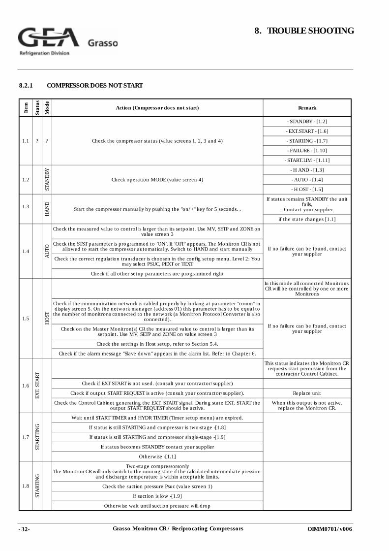
8.2.1 COMPRESSOR DOES NOT START
Item
Stat
us
Mo
de
Action (Compressor does not start) Remark
1.1 ? ? Check the compressor status (value screens 1, 2, 3 and 4)
- STANDBY - [1.2]
- EXT.START - [1.6]
- STARTING - [1.7]
- FAILURE - [1.10]
- START.LIM - [1.11]
1.2
STA
ND
BY
Check operation MODE (value screen 4)
- H AND - [1.3]
- AUTO - [1.4]
- H OST - [1.5]
1.3
HA
ND
Start the compressor manually by pushing the "on/+" key for 5 seconds. .
If status remains STANDBY the unit fails,
- Contact your supplier
if the state changes [1.1]
1.4
AU
TO
Check the measured value to control is larger than its setpoint. Use MV, SETP and ZONE on value screen 3
If no failure can be found, contact your supplier
Check the STST parameter is programmed to ’ON’. If ’OFF’ appears, The Monitron CR is not allowed to start the compressor automatically. Switch to HAND and start manually
Check the correct regulation transducer is choosen in the config setup menu. Level 2: You may select PSUC, PEXT or TEXT
Check if all other setup parameters are programmed right
1.5
HO
ST
In this mode all connected Monitrons CR will be controlled by one or more
Monitrons
Check if the communication network is cabled properly by looking at parameter "comm" in display screen 5. On the network manager (address 01) this parameter has to be equal to
the number of monitrons connected to the network (a Monitron Protocol Converter is also connected).
If no failure can be found, contact your supplier Check on the Master Monitron(s) CR the measured value to control is larger than its
setpoint. Use MV, SETP and ZONE on value screen 3
Check the settings in Host setup, refer to Section 5.4.
Check if the alarm message "Slave down" appears in the alarm list. Refer to Chapter 6.
1.6
EXT.
STA
RT
This status indicates the Monitron CR requests start permission from the
contractor Control Cabinet.
Check if EXT START is not used. (consult your contractor/supplier)
Check if output START REQUEST is active (consult your contractor/supplier). Replace unit
Check the Control Cabinet generating the EXT. START signal. During state EXT. START the output START REQUEST should be active.
When this output is not active, replace the Monitron CR.
1.7
STA
RTT
ING
Wait until START TIMER and HYDR TIMER (Timer setup menu) are expired.
If status is still STARTING and compressor is two-stage -[1.8]
If status is still STARTING and compressor single-stage -[1.9]
If status becomes STANDBY contact your supplier
Otherwise -[1.1]
1.8
STA
RTI
NG
Two-stage compressorsonlyThe Monitron CR will only switch to the running state if the calculated intermediate pressure
and discharge temperature is within acceptable limits.
Check the suction pressure Psuc (value screen 1)
If suction is low -[1.9]
Otherwise wait until suction pressure will drop
- 33-Grasso Monitron CR / Reciprocating Compressors
8. TROUBLE SHOOTING
OIMM0701/v006
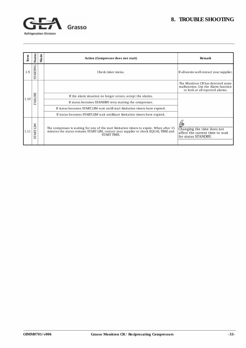
1.9
STA
RTI
NG
Check timer menu. If all seems well contact your supplier.
1.10
FAIL
UR
E
The Monitron CR has detected some malfunction. Use the Alarm function
to look at all reported alarms.
If the alarm situation no longer occurs, accept the alarms.
If status becomes STANDBY retry starting the compressor.
If status becomes START.LIM wait untill start limitation timers have expired.
If status becomes START.LIM wait untillstart limitation timers have expired.
1.11
STA
RT.
LIM
The compressor is waiting for one of the start limitation timers to expire. When after 15 minutes the status remains START LIM, contact your supplier or check EQUAL TIME and
START TIME.
Changing the time does not affect the current time to wait for status STANDBY.
Item
Stat
us
Mo
de
Action (Compressor does not start) Remark
- 34- Grasso Monitron CR / Reciprocating Compressors
8. TROUBLE SHOOTING
OIMM0701/v006
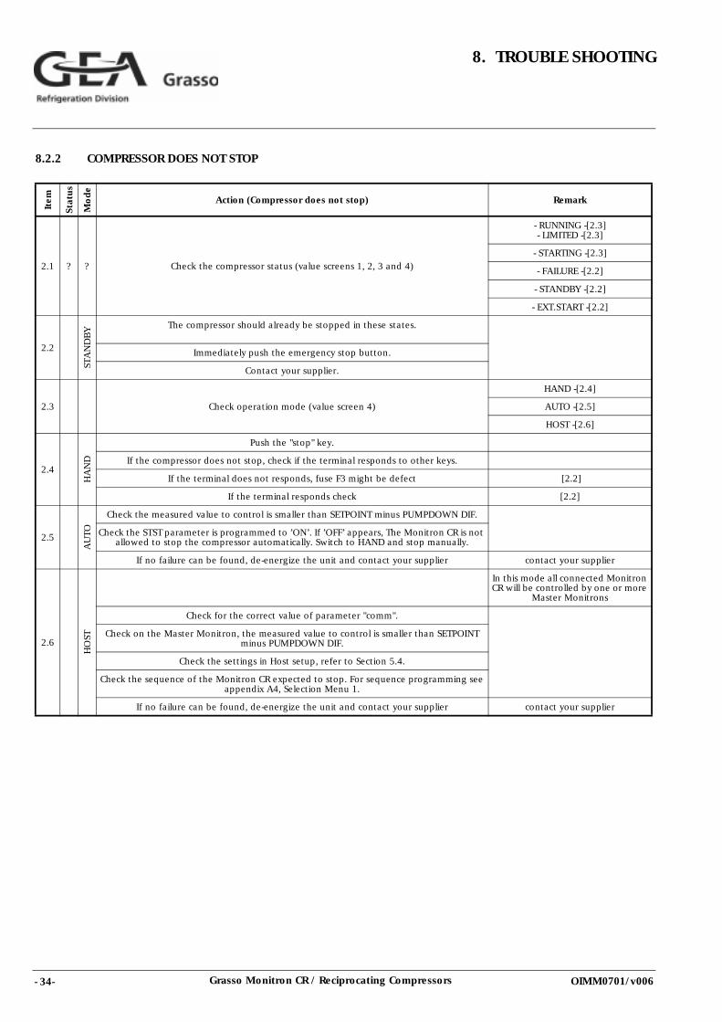
8.2.2 COMPRESSOR DOES NOT STOP
Item
Stat
us
Mo
de
Action (Compressor does not stop) Remark
2.1 ? ? Check the compressor status (value screens 1, 2, 3 and 4)
- RUNNING -[2.3]- LIMITED -[2.3]
- STARTING -[2.3]
- FAILURE -[2.2]
- STANDBY -[2.2]
- EXT.START -[2.2]
2.2
STA
ND
BY The compressor should already be stopped in these states.
Immediately push the emergency stop button.
Contact your supplier.
2.3 Check operation mode (value screen 4)
HAND -[2.4]
AUTO -[2.5]
HOST -[2.6]
2.4
HA
ND
Push the "stop" key.
If the compressor does not stop, check if the terminal responds to other keys.
If the terminal does not responds, fuse F3 might be defect [2.2]
If the terminal responds check [2.2]
2.5
AU
TO
Check the measured value to control is smaller than SETPOINT minus PUMPDOWN DIF.
Check the STST parameter is programmed to ’ON’. If ’OFF’ appears, The Monitron CR is not allowed to stop the compressor automatically. Switch to HAND and stop manually.
If no failure can be found, de-energize the unit and contact your supplier contact your supplier
2.6
HO
ST
In this mode all connected Monitron CR will be controlled by one or more
Master Monitrons
Check for the correct value of parameter "comm".
Check on the Master Monitron, the measured value to control is smaller than SETPOINT minus PUMPDOWN DIF.
Check the settings in Host setup, refer to Section 5.4.
Check the sequence of the Monitron CR expected to stop. For sequence programming see appendix A4, Selection Menu 1.
If no failure can be found, de-energize the unit and contact your supplier contact your supplier
- 35-Grasso Monitron CR / Reciprocating Compressors
8. TROUBLE SHOOTING
OIMM0701/v006
8.2.3 ALARM MESSAGESALARM CONDITION: Used as general alarm indication. The name on the 3th line indicates the alarm reason. Accept this alarm to unlock FAILURE status.
A) Alarms generated by a digital input
An alarm message is generated if one of the digital inputs indicates a failure. An overview of these alarms is given in Section 6.1.1. The name of the input concerned is also listed on the alarm display. This alarm can also be activated by additional safety devices, e.g. extra high pressure safety switch or additional emergency stop button.
B) Alarms generated by exceeding alarm limits
An overview of these alarms is given in Section 6.1.2.Check:1. alarm limits (parameter settings)2. installation (refer to the plant manual)3. sensor(s)
C) Monitron CR internal generated alarm
1. SLAVE STATION DOWNThis alarm indicates a network problem. The Master cannot find one of the Slaves. Check:A, all Slaves are energizedB, all Slaves are connected to the network C, Number of Slaves is programmed in HostNetwork
cable is not damaged2. MONITRON STARTUP / MONITRON RESTART
A, The Monitron CR has restartedB, This could indicate a power failureC, This could indicate malfunction of the unit
8.2.4 TRANSDUCER CHECKSA defect pressure or temperature sensor element is indictated by:1. Screen message ****2. A wrong screen value
In case of a (possibly) defect sensor, Consult your contractor/supplier. (Refer Section 10.6)

- 36- Grasso Monitron CR / Reciprocating Compressors
8. TROUBLE SHOOTING
OIMM0701/v006
- 37-Grasso Monitron CR / Reciprocating Compressors
9. APPENDIX; Flow charts, screens,values ...
OIMM0701/v006
9. APPENDIX; Flow charts, screens, values ...
9.1 FLOW CHART SCREENS
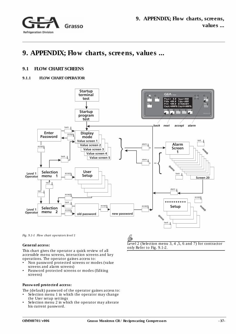
9.1.1 FLOW CHART OPERATOR
Fig. 9.1-1 Flow chart operators level 1
General access:This chart gives the operator a quick review of all accessible menu screens, interaction screens and key operations. The operator gaines access to: • Non password protected screens or modes (value
screens and alarm screens)• Password protected screens or modes (Editing
screens)
Password protected access:The (default) password of the operator gaines access to:• Selection menu 1 in which the operator may change
the User setup settings• Selection menu 2 in which the operator may alterate
his current password.
Level 2 (Selection menu 3, 4 ,5, 6 and 7) for contractor only Refer to Fig. 9.1-2.
- 38- Grasso Monitron CR / Reciprocating Compressors
9. APPENDIX; Flow charts, screens, values...
OIMM0701/v006
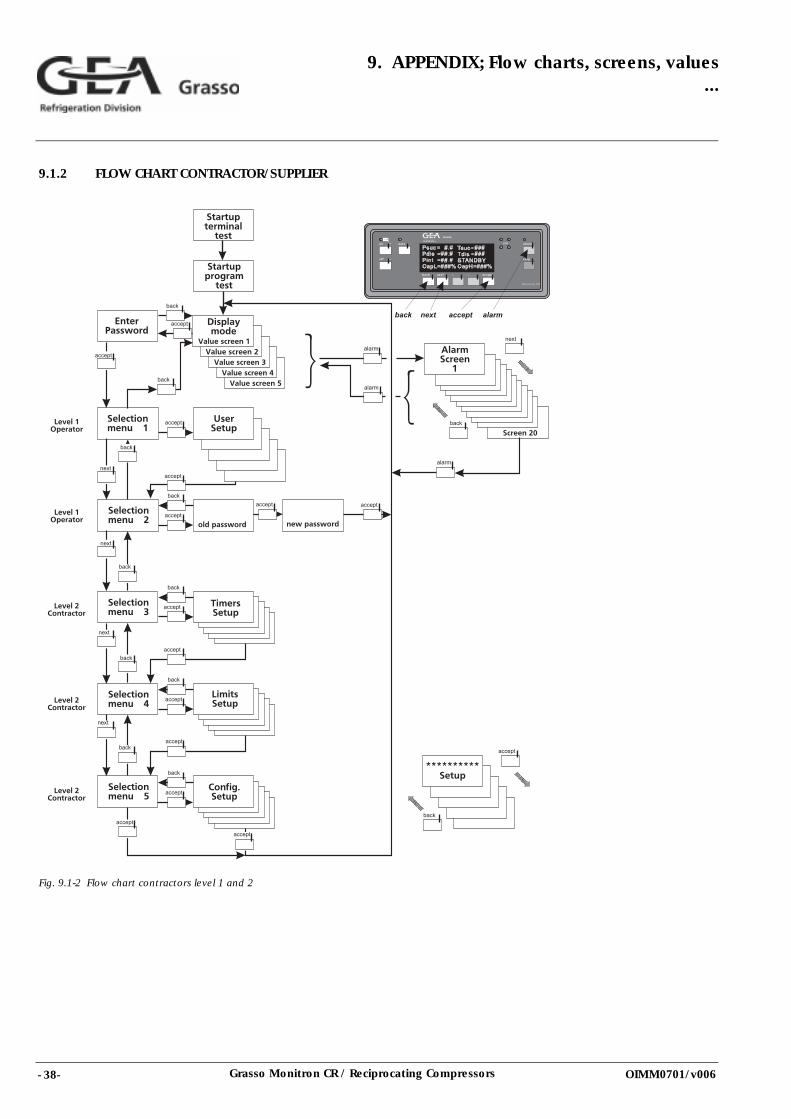
9.1.2 FLOW CHART CONTRACTOR/SUPPLIER
Fig. 9.1-2 Flow chart contractors level 1 and 2

- 39-Grasso Monitron CR / Reciprocating Compressors
9. APPENDIX; Flow charts, screens,values ...
OIMM0701/v006
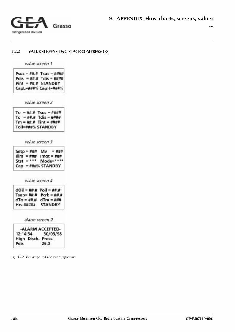
9.2 REVIEW OF VALUE SCREENSThe displayed values in the screens below, represents actual information for single-stage compressors (Section 9.2.1) and for two stage compressor types (Section 9.2.2).
The value screens require no special authorisation level.
Table 9.2-1 Explanation
9.2.1 VALUE SCREENS SINGLE-STAGE AND BOOSTER COMPRESSORS
Fig. 9.2-1 Single-stage and booster compressors
Term Description
Psuc Suction pressure in bar absolute
Tsuc Suction temperature in °C
To Saturation temp. at suction pressure in °C
dTo Suction superheat = Tsuc-To in K
Pdis Discharge pressure in bar absolute
Tdis Discharge temperature in °C
Tc Saturation temperature at discharge pressure in °C
Pint Intermediate pressure at HP suction in bar absolute
Tint LP discharge temperature in °C
Tm Saturation temperature at intermediate pressure in °C
dTm Intermediate superheat = HP suction superheat = HP suction temperature-Tm in K
Poil Oil pressure in bar absolute
Toil Oil temperature in °C
Pcrk Crankcase pressure in bar absolute
dOil Oil differential pressure = Poil-Pcrk in bar
TSep Oil separator temperature in °C
Cap Capacity = percentage of swept volume (single stage)
CapL Percentage of swept volume low stage (two-stage)
CapH Percentage of swept volume high stage(two-stage)
Hrs Running hours
Setp Desired value for capacity control loop in °C
Mode Capacity control mode HAND/AUTO/HOST
StSt Start/stop parameter in capacity control loop ON/OFF
Ilim Current limitation value in Ampere
Imot Motor current in Ampere
Type Selected compressor type
Refr Refrigerant R22/R134a/R404A/NH3
Syst Interstage cooling system A/B/C/D
Rev Software revision number
Addr Address in communication network
Text External temperature sensor for automatic capacity control
Pext External pressure sensor for automatic capacity control
MV Measured value for capacity control loop in °C of the “selected” parameter (Pext, Text, Psuc, etc.)
Circ Refrigeration circuit
Comm Number of Monitrons connected to Network manager
Master Monitron controlling capacity in refrigeration circuit
Seqnr Sequence number used for starting up compressors
Term Description
- 40- Grasso Monitron CR / Reciprocating Compressors
9. APPENDIX; Flow charts, screens, values...
OIMM0701/v006
9.2.2 VALUE SCREENS TWO-STAGE COMPRESSORS
Fig. 9.2-2 Two-stage and booster compressors
- 41-Grasso Monitron CR / Reciprocating Compressors
9. APPENDIX; Flow charts, screens,values ...
OIMM0701/v006
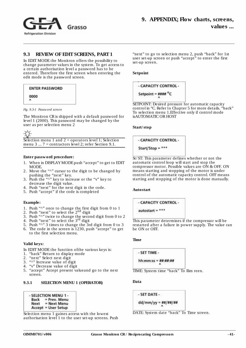
9.3 REVIEW OF EDIT SCREENS, PART 1In EDIT MODE the Monitron offers the possibility to change parameter values in the system. To get access to a certain authorisation level a password has to be entered. Therefore the first screen when entering the edit mode is the password screen.
Fig. 9.3-1 Password screen
The Monitron CR is shipped with a default password for level 1 (2000). This password may be changed by the user as per selection menu 2
Selection menu 1 and 2 = operators level 1; Selection menu 3 ... 7 = contractors level 2; refer Section 9.1.
Enter password procedure:
1. When in DISPLAY MODE push “accept” to get to EDIT MODE.
2. Move the “^” cursor to the digit to be changed by pushing the “next” key.
3. Push the “^” key to increase or the “v” key to decrease the digit value.
4. Push “next” for the next digit in the code.5. Push “accept” if the code is completed
Example:1. Push “^” once to change the first digit from 0 to 12. Push “next” to select the 2nd digit3. Push “^” twice to change the second digit from 0 to 24. Push “next” to select the 3rd digit5. Push “^” 3 times to change the 3rd digit from 0 to 36. The code in the screen is 1230, push “accept” to get
to the first selection menu.
Valid keys:
In EDIT MODE the function ofthe various keys is:1. “back” Return to display mode2. “next” Select next digit3. “^” Increase value of digit4. “v” Decrease value of digit5. “accept” Accept present valueand go to the next
screen.
9.3.1 SELECTION MENU 1 (OPERATOR)
Selection menu 1 gaines access with the lowest authorisation level 1 to the user set-up screens. Push
“next” to go to selection menu 2, push “back” for 1st user set-up screen or push “accept” to enter the first set-up screen.
Setpoint
SETPOINT: Desired pressure for automatic capacity control in °C. Refer to Chapter 5 for more details. “back” To selection menu 1.Effective only if control mode isAUTOMATIC OR HOST
Start/stop
St/ST: This parameter defines whether or not the automatic control loop will start and stop the compressor motor. Possible values are ON & OFF. ON means starting and stopping of the motor is under control of the automatic capacity control. OFF means starting and stopping of the motor is done manually.
Autostart
This parameter determines if the compressor will be restarted after a failure in power supply. The value can be ON or OFF.
Time
TIME: System time “back” To Ilim reen.
Data
DATE: System date “back” To Time screen.
- 42- Grasso Monitron CR / Reciprocating Compressors
9. APPENDIX; Flow charts, screens, values...
OIMM0701/v006
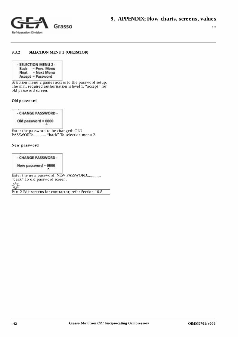
9.3.2 SELECTION MENU 2 (OPERATOR)
Selection menu 2 gaines access to the password setup. The min. required authorisation is level 1. “accept” for old password screen.
Old password
Enter the password to be changed: OLD PASSWORD:............ “back” To selection menu 2.
New password
Enter the new password: NEW PASSWORD:............ “back” To old password screen.
Part 2 Edit screens for contractor; refer Section 10.8
- 43-Grasso Monitron CR / Reciprocating Compressors
10. INSTALLATION AND MAINTENANCE(Contractor only)
OIMM0701/v006
10.INSTALLATION AND MAINTENANCE (Contractor only)
This chapter is for contractors only. Some sections are only availble in English.
10.1 INSTALLING
10.1.1 INTRODUCTIONOn a factory mounted Monitron CR most connections and settings have already been madeby Grasso. This section describes what connections and settings have to be made on site by the contractor. Refer Section 10.9to for the wiring diagrams and for a review of the cable entries of the control unit.Refer to Section 10.1.3 and Section 10.1.4for an overview of all input and output signals that are used for standard, optional or only for two-stage compressors.
10.1.2 POWER SUPPLY
The Monitron CR is factory wired for 230 VAC or 115 VAC power supply. Connect the power feed cables to connector X301 and connect the earthing cable to the central earthing strip. Refer Section 10.9 , figure CR-E01 and CR-E03.
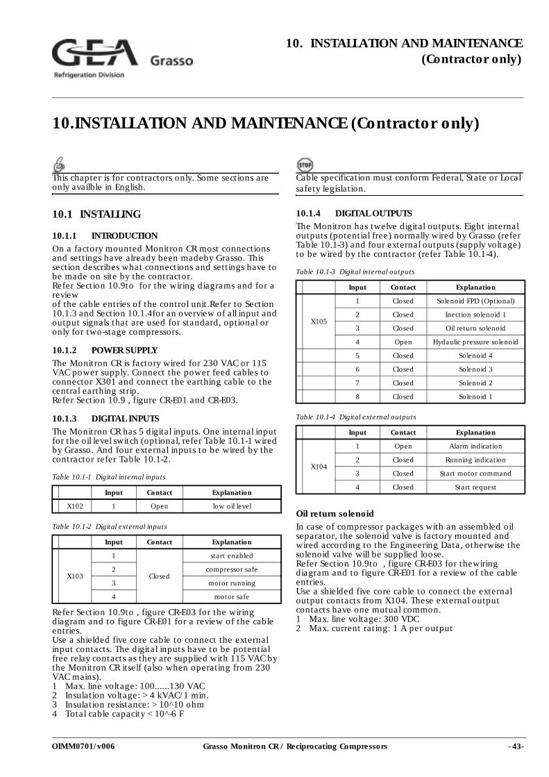
10.1.3 DIGITAL INPUTSThe Monitron CR has 5 digital inputs. One internal input for the oil level switch (optional, refer Table 10.1-1 wired by Grasso. And four external inputs to be wired by the contractor refer Table 10.1-2.
Table 10.1-1 Digital internal inputs
Table 10.1-2 Digital external inputs
Refer Section 10.9to , figure CR-E03 for the wiring diagram and to figure CR-E01 for a review of the cable entries. Use a shielded five core cable to connect the external input contacts. The digital inputs have to be potential free relay contacts as they are supplied with 115 VAC by the Monitron CR itself (also when operating from 230 VAC mains). 1 Max. line voltage: 100......130 VAC2 Insulation voltage: > 4 kVAC/1 min.3 Insulation resistance: > 10^10 ohm4 Total cable capacity < 10^-6 F
Cable specification must conform Federal, State or Local safety legislation.
10.1.4 DIGITAL OUTPUTSThe Monitron has twelve digital outputs. Eight internal outputs (potential free) normally wired by Grasso (refer Table 10.1-3) and four external outputs (supply voltage) to be wired by the contractor (refer Table 10.1-4).
Table 10.1-3 Digital internal outputs
Table 10.1-4 Digital external outputs
Oil return solenoidIn case of compressor packages with an assembled oil separator, the solenoid valve is factory mounted and wired according to the Engineering Data, otherwise the solenoid valve will be supplied loose. Refer Section 10.9to , figure CR-E03 for thewiring diagram and to figure CR-E01 for a review of the cable entries. Use a shielded five core cable to connect the external output contacts from X104. These external output contacts have one mutual common. 1 Max. line voltage: 300 VDC2 Max. current rating: 1 A per output
Input Contact Explanation
X102 1 Open low oil level
Input Contact Explanation
X103
1
Closed
start enabled
2 compressor safe
3 motor running
4 motor safe
Input Contact Explanation
X105
1 Closed Solenoid FPD (Optional)
2 Closed Inection solenoid 1
3 Closed Oil return solenoid
4 Open Hydaulic pressure solenoid
5 Closed Solenoid 4
6 Closed Solenoid 3
7 Closed Solenoid 2
8 Closed Solenoid 1
Input Contact Explanation
X104
1 Open Alarm indication
2 Closed Running indication
3 Closed Start motor command
4 Closed Start request
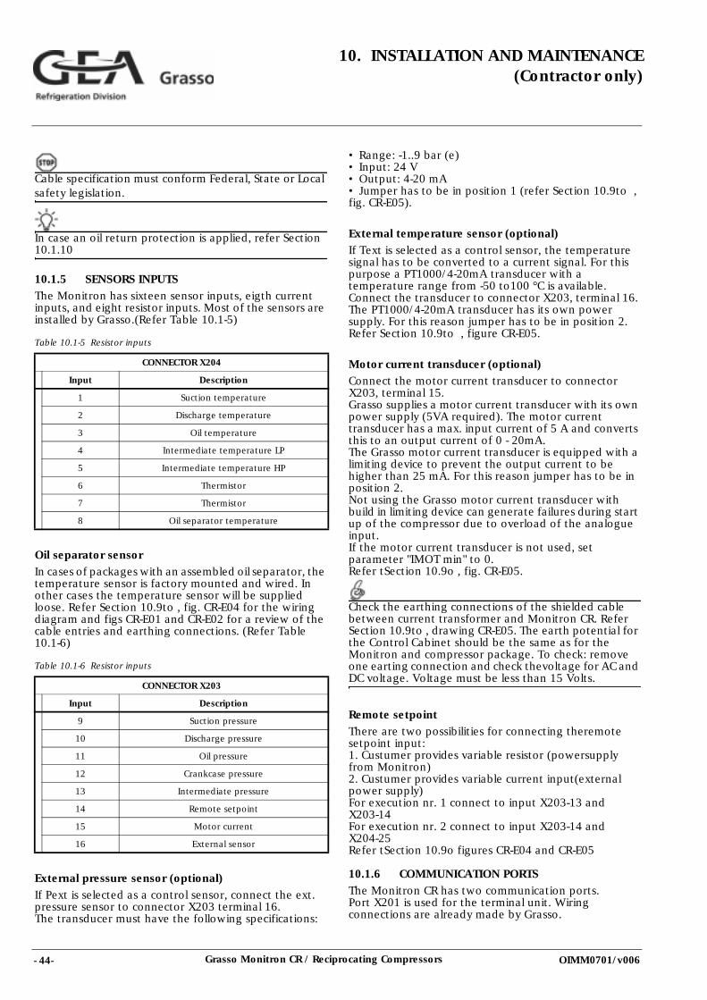
- 44- Grasso Monitron CR / Reciprocating Compressors
10. INSTALLATION AND MAINTENANCE(Contractor only)
OIMM0701/v006
Cable specification must conform Federal, State or Local safety legislation.
In case an oil return protection is applied, refer Section 10.1.10
10.1.5 SENSORS INPUTSThe Monitron has sixteen sensor inputs, eigth current inputs, and eight resistor inputs. Most of the sensors are installed by Grasso.(Refer Table 10.1-5)
Table 10.1-5 Resistor inputs
Oil separator sensorIn cases of packages with an assembled oil separator, the temperature sensor is factory mounted and wired. In other cases the temperature sensor will be supplied loose. Refer Section 10.9to , fig. CR-E04 for the wiring diagram and figs CR-E01 and CR-E02 for a review of the cable entries and earthing connections. (Refer Table 10.1-6)
Table 10.1-6 Resistor inputs
External pressure sensor (optional)
If Pext is selected as a control sensor, connect the ext. pressure sensor to connector X203 terminal 16. The transducer must have the following specifications:
• Range: -1..9 bar (e) • Input: 24 V • Output: 4-20 mA • Jumper has to be in position 1 (refer Section 10.9to , fig. CR-E05).
External temperature sensor (optional)If Text is selected as a control sensor, the temperature signal has to be converted to a current signal. For this purpose a PT1000/4-20mA transducer with a temperature range from -50 to100 °C is available. Connect the transducer to connector X203, terminal 16. The PT1000/4-20mA transducer has its own power supply. For this reason jumper has to be in position 2. Refer Section 10.9to , figure CR-E05.
Motor current transducer (optional)Connect the motor current transducer to connector X203, terminal 15. Grasso supplies a motor current transducer with its own power supply (5VA required). The motor current transducer has a max. input current of 5 A and converts this to an output current of 0 - 20mA. The Grasso motor current transducer is equipped with a limiting device to prevent the output current to be higher than 25 mA. For this reason jumper has to be in position 2. Not using the Grasso motor current transducer with build in limiting device can generate failures during start up of the compressor due to overload of the analogue input. If the motor current transducer is not used, set parameter "IMOT min" to 0. Refer tSection 10.9o , fig. CR-E05.
Check the earthing connections of the shielded cable between current transformer and Monitron CR. Refer Section 10.9to , drawing CR-E05. The earth potential for the Control Cabinet should be the same as for the Monitron and compressor package. To check: remove one earting connection and check thevoltage for AC and DC voltage. Voltage must be less than 15 Volts.
Remote setpointThere are two possibilities for connecting theremote setpoint input:1. Custumer provides variable resistor (powersupply from Monitron)2. Custumer provides variable current input(external power supply)For execution nr. 1 connect to input X203-13 and X203-14For execution nr. 2 connect to input X203-14 and X204-25 Refer tSection 10.9o figures CR-E04 and CR-E05
10.1.6 COMMUNICATION PORTSThe Monitron CR has two communication ports. Port X201 is used for the terminal unit. Wiring connections are already made by Grasso.
CONNECTOR X204
Input Description
1 Suction temperature
2 Discharge temperature
3 Oil temperature
4 Intermediate temperature LP
5 Intermediate temperature HP
6 Thermistor
7 Thermistor
8 Oil separator temperature
CONNECTOR X203
Input Description
9 Suction pressure
10 Discharge pressure
11 Oil pressure
12 Crankcase pressure
13 Intermediate pressure
14 Remote setpoint
15 Motor current
16 External sensor
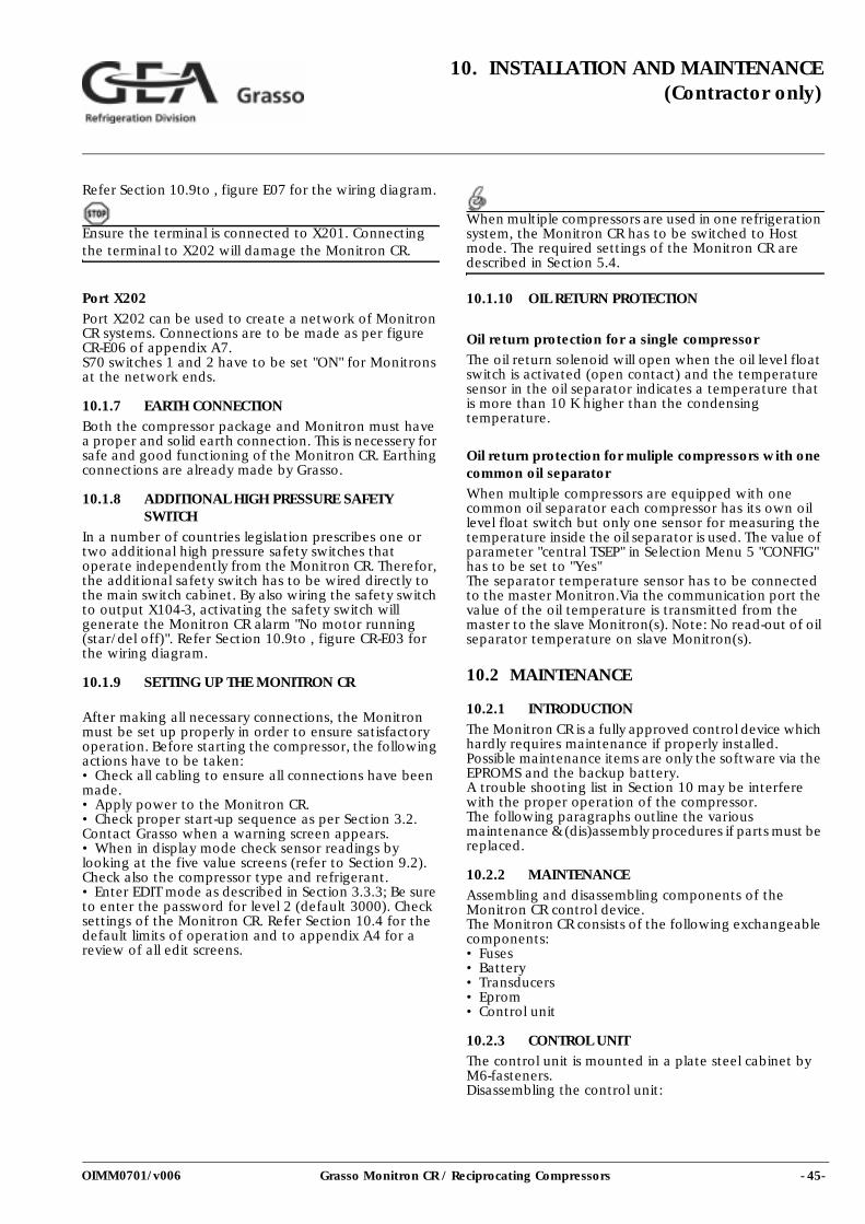
- 45-Grasso Monitron CR / Reciprocating Compressors
10. INSTALLATION AND MAINTENANCE(Contractor only)
OIMM0701/v006
Refer Section 10.9to , figure E07 for the wiring diagram.
Ensure the terminal is connected to X201. Connecting the terminal to X202 will damage the Monitron CR.
Port X202
Port X202 can be used to create a network of Monitron CR systems. Connections are to be made as per figure CR-E06 of appendix A7. S70 switches 1 and 2 have to be set "ON" for Monitrons at the network ends.
10.1.7 EARTH CONNECTIONBoth the compressor package and Monitron must have a proper and solid earth connection. This is necessery for safe and good functioning of the Monitron CR. Earthing connections are already made by Grasso.
10.1.8 ADDITIONAL HIGH PRESSURE SAFETY SWITCH
In a number of countries legislation prescribes one or two additional high pressure safety switches that operate independently from the Monitron CR. Therefor, the additional safety switch has to be wired directly to the main switch cabinet. By also wiring the safety switch to output X104-3, activating the safety switch will generate the Monitron CR alarm "No motor running (star/del off)". Refer Section 10.9to , figure CR-E03 for the wiring diagram.
10.1.9 SETTING UP THE MONITRON CR
After making all necessary connections, the Monitron must be set up properly in order to ensure satisfactory operation. Before starting the compressor, the following actions have to be taken:• Check all cabling to ensure all connections have been made.• Apply power to the Monitron CR. • Check proper start-up sequence as per Section 3.2. Contact Grasso when a warning screen appears. • When in display mode check sensor readings by looking at the five value screens (refer to Section 9.2). Check also the compressor type and refrigerant. • Enter EDIT mode as described in Section 3.3.3; Be sure to enter the password for level 2 (default 3000). Check settings of the Monitron CR. Refer Section 10.4 for the default limits of operation and to appendix A4 for a review of all edit screens.
When multiple compressors are used in one refrigeration system, the Monitron CR has to be switched to Host mode. The required settings of the Monitron CR are described in Section 5.4.
10.1.10 OIL RETURN PROTECTION
Oil return protection for a single compressorThe oil return solenoid will open when the oil level float switch is activated (open contact) and the temperature sensor in the oil separator indicates a temperature that is more than 10 K higher than the condensing temperature.
Oil return protection for muliple compressors with one common oil separator
When multiple compressors are equipped with one common oil separator each compressor has its own oil level float switch but only one sensor for measuring the temperature inside the oil separator is used. The value of parameter "central TSEP" in Selection Menu 5 "CONFIG" has to be set to "Yes" The separator temperature sensor has to be connected to the master Monitron.Via the communication port the value of the oil temperature is transmitted from the master to the slave Monitron(s). Note: No read-out of oil separator temperature on slave Monitron(s).
10.2 MAINTENANCE
10.2.1 INTRODUCTION
The Monitron CR is a fully approved control device which hardly requires maintenance if properly installed. Possible maintenance items are only the software via the EPROMS and the backup battery. A trouble shooting list in Section 10 may be interfere with the proper operation of the compressor. The following paragraphs outline the various maintenance & (dis)assembly procedures if parts must be replaced.
10.2.2 MAINTENANCEAssembling and disassembling components of the Monitron CR control device. The Monitron CR consists of the following exchangeable components: • Fuses • Battery • Transducers • Eprom • Control unit
10.2.3 CONTROL UNITThe control unit is mounted in a plate steel cabinet by M6-fasteners. Disassembling the control unit:
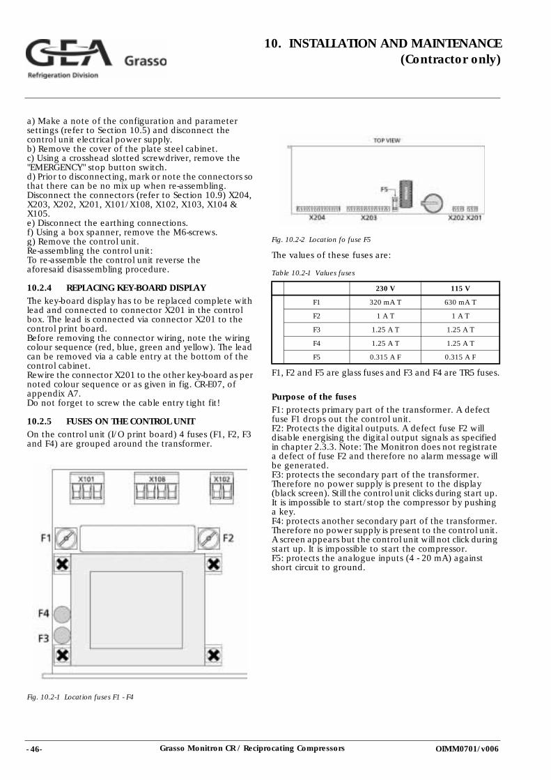
- 46- Grasso Monitron CR / Reciprocating Compressors
10. INSTALLATION AND MAINTENANCE(Contractor only)
OIMM0701/v006
a) Make a note of the configuration and parameter settings (refer to Section 10.5) and disconnect the control unit electrical power supply. b) Remove the cover of the plate steel cabinet. c) Using a crosshead slotted screwdriver, remove the "EMERGENCY" stop button switch. d) Prior to disconnecting, mark or note the connectors so that there can be no mix up when re-assembling. Disconnect the connectors (refer to Section 10.9) X204, X203, X202, X201, X101/X108, X102, X103, X104 & X105. e) Disconnect the earthing connections. f) Using a box spanner, remove the M6-screws. g) Remove the control unit. Re-assembling the control unit: To re-assemble the control unit reverse the aforesaid disassembling procedure.
10.2.4 REPLACING KEY-BOARD DISPLAYThe key-board display has to be replaced complete with lead and connected to connector X201 in the control box. The lead is connected via connector X201 to the control print board. Before removing the connector wiring, note the wiring colour sequence (red, blue, green and yellow). The lead can be removed via a cable entry at the bottom of the control cabinet. Rewire the connector X201 to the other key-board as per noted colour sequence or as given in fig. CR-E07, of appendix A7. Do not forget to screw the cable entry tight fit!
10.2.5 FUSES ON THE CONTROL UNITOn the control unit (I/O print board) 4 fuses (F1, F2, F3 and F4) are grouped around the transformer.
Fig. 10.2-1 Location fuses F1 - F4
Fig. 10.2-2 Location fo fuse F5
The values of these fuses are:
Table 10.2-1 Values fuses
F1, F2 and F5 are glass fuses and F3 and F4 are TR5 fuses.
Purpose of the fusesF1: protects primary part of the transformer. A defect fuse F1 drops out the control unit. F2: Protects the digital outputs. A defect fuse F2 will disable energising the digital output signals as specified in chapter 2.3.3. Note: The Monitron does not registrate a defect of fuse F2 and therefore no alarm message will be generated. F3: protects the secondary part of the transformer. Therefore no power supply is present to the display (black screen). Still the control unit clicks during start up. It is impossible to start/stop the compressor by pushing a key. F4: protects another secondary part of the transformer. Therefore no power supply is present to the control unit. A screen appears but the control unit will not click during start up. It is impossible to start the compressor. F5: protects the analogue inputs (4 - 20 mA) against short circuit to ground.
230 V 115 V
F1 320 mA T 630 mA T
F2 1 A T 1 A T
F3 1.25 A T 1.25 A T
F4 1.25 A T 1.25 A T
F5 0.315 A F 0.315 A F
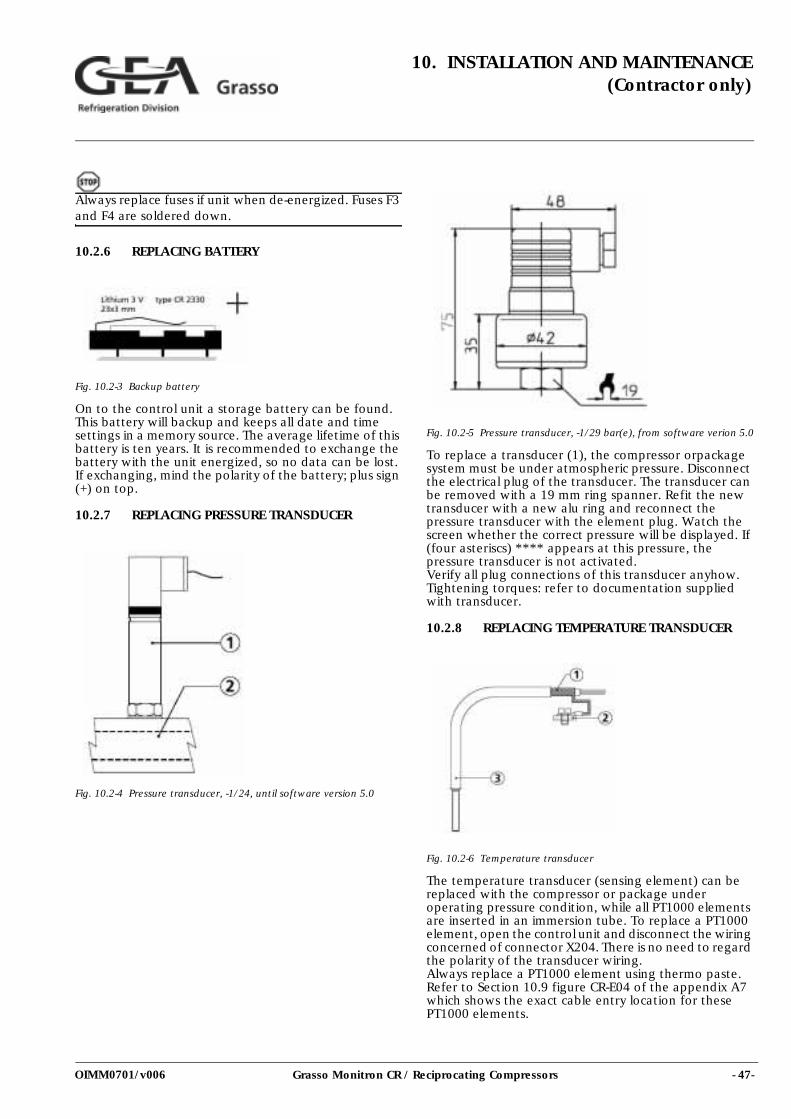
- 47-Grasso Monitron CR / Reciprocating Compressors
10. INSTALLATION AND MAINTENANCE(Contractor only)
OIMM0701/v006
Always replace fuses if unit when de-energized. Fuses F3 and F4 are soldered down.
10.2.6 REPLACING BATTERY
Fig. 10.2-3 Backup battery
On to the control unit a storage battery can be found. This battery will backup and keeps all date and time settings in a memory source. The average lifetime of this battery is ten years. It is recommended to exchange the battery with the unit energized, so no data can be lost. If exchanging, mind the polarity of the battery; plus sign (+) on top.
10.2.7 REPLACING PRESSURE TRANSDUCER
Fig. 10.2-4 Pressure transducer, -1/24, until software version 5.0
Fig. 10.2-5 Pressure transducer, -1/29 bar(e), from software verion 5.0
To replace a transducer (1), the compressor orpackage system must be under atmospheric pressure. Disconnect the electrical plug of the transducer. The transducer can be removed with a 19 mm ring spanner. Refit the new transducer with a new alu ring and reconnect the pressure transducer with the element plug. Watch the screen whether the correct pressure will be displayed. If (four asteriscs) **** appears at this pressure, the pressure transducer is not activated. Verify all plug connections of this transducer anyhow. Tightening torques: refer to documentation supplied with transducer.
10.2.8 REPLACING TEMPERATURE TRANSDUCER
Fig. 10.2-6 Temperature transducer
The temperature transducer (sensing element) can be replaced with the compressor or package under operating pressure condition, while all PT1000 elements are inserted in an immersion tube. To replace a PT1000 element, open the control unit and disconnect the wiring concerned of connector X204. There is no need to regard the polarity of the transducer wiring. Always replace a PT1000 element using thermo paste. Refer to Section 10.9 figure CR-E04 of the appendix A7 which shows the exact cable entry location for these PT1000 elements.
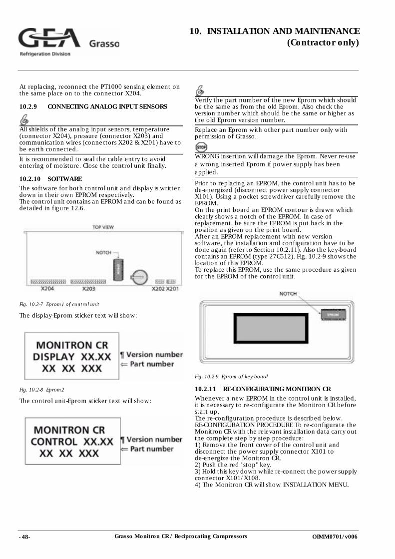
- 48- Grasso Monitron CR / Reciprocating Compressors
10. INSTALLATION AND MAINTENANCE(Contractor only)
OIMM0701/v006
At replacing, reconnect the PT1000 sensing element on the same place on to the connector X204.
10.2.9 CONNECTING ANALOG INPUT SENSORS
All shields of the analog input sensors, temperature (connector X204), pressure (connector X203) and communication wires (connectors X202 & X201) have to be earth connected.
It is recommended to seal the cable entry to avoid entering of moisture. Close the control unit finally.
10.2.10 SOFTWAREThe software for both control unit and display is written down in their own EPROM respectively. The control unit contains an EPROM and can be found as detailed in figure 12.6.
Fig. 10.2-7 Eprom1 of control unit
The display-Eprom sticker text will show:
Fig. 10.2-8 Eprom2
The control unit-Eprom sticker text will show:
Verify the part number of the new Eprom which should be the same as from the old Eprom. Also check the version number which should be the same or higher as the old Eprom version number.
Replace an Eprom with other part number only with permission of Grasso.
WRONG insertion will damage the Eprom. Never re-use a wrong inserted Eprom if power supply has been applied.
Prior to replacing an EPROM, the control unit has to be de-energized (disconnect power supply connector X101). Using a pocket screwdriver carefully remove the EPROM. On the print board an EPROM contour is drawn which clearly shows a notch of the EPROM. In case of replacement, be sure the EPROM is put back in the position as given on the print board. After an EPROM replacement with new version software, the installation and configuration have to be done again (refer to Section 10.2.11). Also the key-board contains an EPROM (type 27C512). Fig. 10.2-9 shows the location of this EPROM. To replace this EPROM, use the same procedure as given for the EPROM of the control unit.
Fig. 10.2-9 Eprom of key-board
10.2.11 RE-CONFIGURATING MONITRON CRWhenever a new EPROM in the control unit is installed, it is necessary to re-configurate the Monitron CR before start up. The re-configuration procedure is described below. RE-CONFIGURATION PROCEDURE To re-configurate the Monitron CR with the relevant installation data carry out the complete step by step procedure: 1) Remove the front cover of the control unit and disconnect the power supply connector X101 to de-energize the Monitron CR. 2) Push the red "stop" key. 3) Hold this key down while re-connect the power supply connector X101/X108. 4) The Monitron CR will show INSTALLATION MENU.
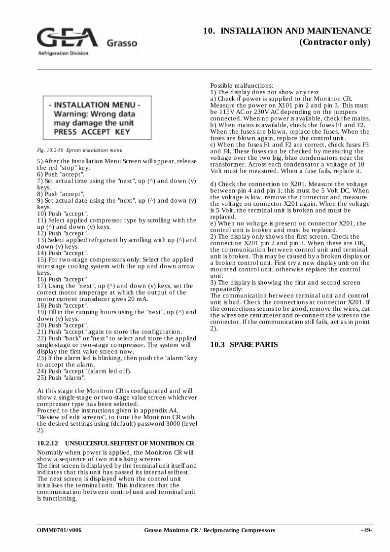
- 49-Grasso Monitron CR / Reciprocating Compressors
10. INSTALLATION AND MAINTENANCE(Contractor only)
OIMM0701/v006
Fig. 10.2-10 Eprom installation menu
5) After the Installation Menu Screen will appear, release the red "stop" key. 6) Push "accept".7) Set actual time using the "next", up (^) and down (v) keys. 8) Push "accept". 9) Set actual date using the "next", up (^) and down (v) keys. 10) Push "accept". 11) Select applied compressor type by scrolling with the up (^) and down (v) keys. 12) Push "accept". 13) Select applied refrgerant by scrolling with up (^) and down (v) keys. 14) Push "accept". 15) For two-stage compressors only: Select the applied interstage cooling system with the up and down arrow keys. 16) Push "accept" 17) Using the "next", up (^) and down (v) keys, set the correct motor amperage at which the output of the motor current transducer gives 20 mA. 18) Push "accept". 19) Fill in the running hours using the "next", up (^) and down (v) keys. 20) Push "accept". 21) Push "accept" again to store the configuration. 22) Push "back" or "next" to select and store the applied single-stage or two-stage compressor. The system will display the first value screen now. 23) If the alarm led is blinking, then push the "alarm" key to accept the alarm. 24) Push "accept" (alarm led off). 25) Push "alarm".
At this stage the Monitron CR is configurated and will show a single-stage or two-stage value screen whichever compressor type has been selected. Proceed to the instructions given in appendix A4, "Review of edit screens", to tune the Monitron CR with the desired settings using (default) password 3000 (level 2).
10.2.12 UNSUCCESFUL SELFTEST OF MONITRON CRNormally when power is applied, the Monitron CR will show a sequence of two initialising screens. The first screen is displayed by the terminal unit itself and indicates that this unit has passed its internal selftest. The next screen is displayed when the control unit initialises the terminal unit. This indicates that the communication between control unit and terminal unit is functioning.
Possible malfunctions: 1) The display does not show any text a) Check if power is supplied to the Monitron CR. Measure the power on X101 pin 2 and pin 3. This must be 115V AC or 230V AC depending on the jumpers connected. When no power is available, check the mains. b) When mains is available, check the fuses F1 and F2. When the fuses are blown, replace the fuses. When the fuses are blown again, replace the control unit. c) When the fuses F1 and F2 are correct, check fuses F3 and F4. These fuses can be checked by measuring the voltage over the two big, blue condensators near the transformer. Across each condensator a voltage of 10 Volt must be measured. When a fuse fails, replace it.
d) Check the connection to X201. Measure the voltage between pin 4 and pin 1; this must be 5 Volt DC. When the voltage is low, remove the connector and measure the voltage on connector X201 again. When the voltage is 5 Volt, the terminal unit is broken and must be replaced. e) When no voltage is present on connector X201, the control unit is broken and must be replaced. 2) The display only shows the first screen. Check the connection X201 pin 2 and pin 3. When these are OK, the communication between control unit and terminal unit is broken. This may be caused by a broken display or a broken control unit. First try a new display unit on the mounted control unit, otherwise replace the control unit. 3) The display is showing the first and second screen repeatedly: The communication between terminal unit and control unit is bad. Check the connections at connector X201. If the connections seems to be good, remove the wires, cut the wires one centimeter and re-connect the wires to the connector. If the communication still fails, act as in point 2).
10.3 SPARE PARTS
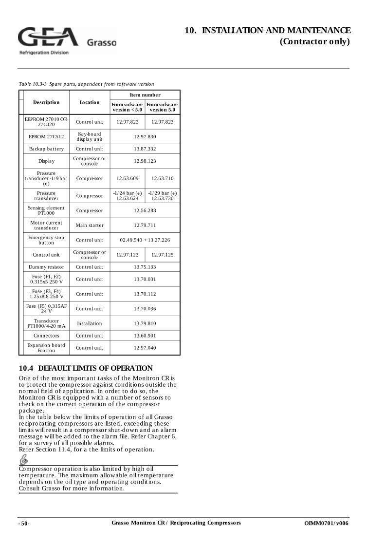
- 50- Grasso Monitron CR / Reciprocating Compressors
10. INSTALLATION AND MAINTENANCE(Contractor only)
OIMM0701/v006
Table 10.3-1 Spare parts, dependant from software version
10.4 DEFAULT LIMITS OF OPERATIONOne of the most important tasks of the Monitron CR is to protect the compressor against conditions outside the normal field of application. In order to do so, the Monitron CR is equipped with a number of sensors to check on the correct operation of the compressor package.In the table below the limits of operation of all Grasso reciprocating compressors are listed, exceeding these limits will result in a compressor shut-down and an alarm message will be added to the alarm file. Refer Chapter 6, for a survey of all possible alarms. Refer Section 11.4, for a the limits of operation.
Compressor operation is also limited by high oil temperature. The maximum allowable oil temperature depends on the oil type and operating conditions. Consult Grasso for more information.
Description Location
Item number
From sofware version < 5.0
From sofware version 5.0
EEPROM 27010 OR 27C020 Control unit 12.97.822 12.97.823
EPROM 27C512 Key-board display unit 12.97.830
Backup battery Control unit 13.87.332
Display Compressor or console 12.98.123
Pressure transducer -1/9 bar
(e)Compressor 12.63.609 12.63.710
Pressure transducer Compressor -1/24 bar (e)
12.63.624-1/29 bar (e)
12.63.730
Sensing element PT1000 Compressor 12.56.288
Motor current transducer Main starter 12.79.711
Emergency stop button Control unit 02.49.540 + 13.27.226
Control unit Compressor or console 12.97.123 12.97.125
Dummy resistor Control unit 13.75.133
Fuse (F1, F2) 0.315x5 250 V Control unit 13.70.031
Fuse (F3, F4) 1.25x8.8 250 V Control unit 13.70.112
Fuse (F5) 0.315AF 24 V Control unit 13.70.036
Transducer PT1000/4-20 mA Installation 13.79.810
Connectors Control unit 13.60.901
Expansion board Ecotron Control unit 12.97.040
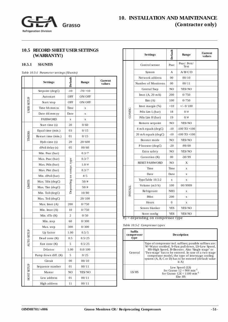
- 51-Grasso Monitron CR / Reciprocating Compressors
10. INSTALLATION AND MAINTENANCE(Contractor only)
OIMM0701/v006
10.5 RECORD SHEET USER SETTINGS (WARRANTY!)
10.5.1 SI-UNITS
Table 10.5-1 Parameter settings (SI-units)
#) = depending on compressor type
Table 10.5-2 Compressor types
Settings
Def
ault
Range Currentvalues
USE
R S
ETU
P
Setpoint (degC) -10 -70/+10
Autostart OFF ON/OFF
Start/stop OFF ON/OFF
Time hh:mm:ss Time x
Date dd:mm:yy Date x
PASSWORD x x
TIM
ERS
Start time (s) 20 0/60
Equal time (min.) 03 0/15
Restart time (min.) 01 0/15
Hydr.time (s) 20 20/600
dPoil delay (s) 05 00/60
LIM
ITS
Min. Psuc (bar)
Dep
end
ing
on
co
mp
r. t
ype
0.3/7
Max. Psuc (bar) 0.3/7
Max. Pdis (bar) 1.0/#
Max. Pint (bar) 0.3/7
Min. dPoil (bar) #/5
Max. Tdis (degC) 50/#
Max. Tint (degC) 50/#
Min. Toil (degC) 10/80
Max. Toil (degC) 20/100
Max. Imot (A) 200 0/750
Min. Imot (A) 10 0/750
Min. dTo (K) 2 0/50
AU
TO S
ETU
P
Min. step 60 0/300
Max. step 300 0/300
Up factor 1.00 0.5/5
Dead zone (K) 0.5 0.5/25
Fast zone (K) 5 0.5/25
D-factor 1.00 0.0/100
Pump down diff. (K) 5 0/25
HO
ST S
ETU
P
Circuit 00 00/10
Sequence number 01 00/11
Master NO YES/NO
Low address 01 00/11
High address 11 00/11
CO
NFI
G
Control sensor Psuc Psuc/ Pext/ Text
System A A/B/C/D
Network address 00 00/10
Number of Monitrons 00 00/11
Central Tsep NO YES/NO
Imot (A, 20 mA) 200 0/750
Ilim (A) 100 0/750
Imot margin (%) +10 +/- 0/100
Pdis Lim L (bar) 18 0/#
Pdis Lim H (bar) 19 0/#
Remote setpoint NO YES/NO
4 mA equals (degC) -10 -100 TO +100
20 mA equals (degC) -10 -100 TO +100
Booster mode NO YES/NO
P booster (degC) -20 -99/00
Extra safety NO YES/NO
Correction (K) 00 -30/99
RESET PASSWORD NO X
INST
ALL
Time Time x
Date Date x
TypeTable 10.5-2 x x
Volume (m3/h) 100 00/9999
Refrigerant NH3 x
IMot 200 x
Hours 0 x
Screen blanker YES YES/NO
Store config YES YES/NO
Suffix compressor
typeDescription
General
Type of compressor incl. suffixes; possible suffixes are: W=Water coolded, S=Fast pull down, LS=Low Speed,
HS=High Speed, B=Booster. Also ‘Single stage’ or ‘Two-stage’ has to be entered. In case of a two stage
compressor model, the type of interstage cooling system (A, B, C or D) has to be entered (default value
is A)
LS/HS
Low Speed (LS)for Grasso 12 < 900 min-1
for Grasso 12E < 1100 min-1
Else HS
Settings
Def
ault
Range Currentvalues
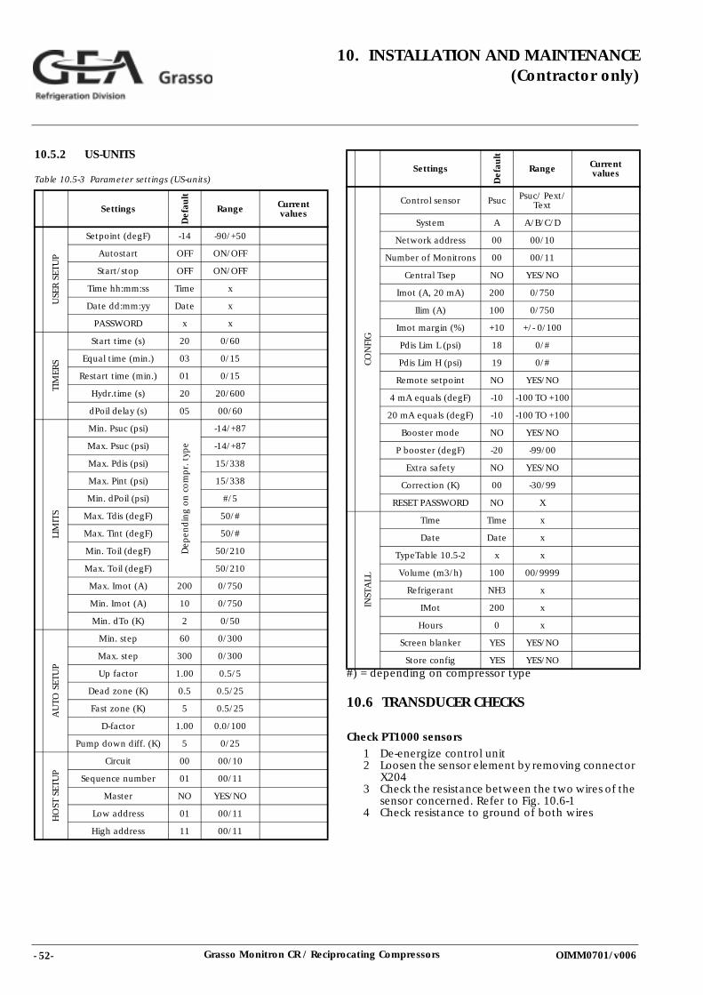
- 52- Grasso Monitron CR / Reciprocating Compressors
10. INSTALLATION AND MAINTENANCE(Contractor only)
OIMM0701/v006
10.5.2 US-UNITS
Table 10.5-3 Parameter settings (US-units)
#) = depending on compressor type
10.6 TRANSDUCER CHECKS
Check PT1000 sensors1 De-energize control unit2 Loosen the sensor element by removing connector
X2043 Check the resistance between the two wires of the
sensor concerned. Refer to Fig. 10.6-14 Check resistance to ground of both wires
Settings
Def
ault
Range Currentvalues
USE
R S
ETU
P
Setpoint (degF) -14 -90/+50
Autostart OFF ON/OFF
Start/stop OFF ON/OFF
Time hh:mm:ss Time x
Date dd:mm:yy Date x
PASSWORD x x
TIM
ERS
Start time (s) 20 0/60
Equal time (min.) 03 0/15
Restart time (min.) 01 0/15
Hydr.time (s) 20 20/600
dPoil delay (s) 05 00/60
LIM
ITS
Min. Psuc (psi)
Dep
end
ing
on
co
mp
r. t
ype
-14/+87
Max. Psuc (psi) -14/+87
Max. Pdis (psi) 15/338
Max. Pint (psi) 15/338
Min. dPoil (psi) #/5
Max. Tdis (degF) 50/#
Max. Tint (degF) 50/#
Min. Toil (degF) 50/210
Max. Toil (degF) 50/210
Max. Imot (A) 200 0/750
Min. Imot (A) 10 0/750
Min. dTo (K) 2 0/50
AU
TO S
ETU
P
Min. step 60 0/300
Max. step 300 0/300
Up factor 1.00 0.5/5
Dead zone (K) 0.5 0.5/25
Fast zone (K) 5 0.5/25
D-factor 1.00 0.0/100
Pump down diff. (K) 5 0/25
HO
ST S
ETU
P
Circuit 00 00/10
Sequence number 01 00/11
Master NO YES/NO
Low address 01 00/11
High address 11 00/11
CO
NFI
G
Control sensor Psuc Psuc/ Pext/ Text
System A A/B/C/D
Network address 00 00/10
Number of Monitrons 00 00/11
Central Tsep NO YES/NO
Imot (A, 20 mA) 200 0/750
Ilim (A) 100 0/750
Imot margin (%) +10 +/- 0/100
Pdis Lim L (psi) 18 0/#
Pdis Lim H (psi) 19 0/#
Remote setpoint NO YES/NO
4 mA equals (degF) -10 -100 TO +100
20 mA equals (degF) -10 -100 TO +100
Booster mode NO YES/NO
P booster (degF) -20 -99/00
Extra safety NO YES/NO
Correction (K) 00 -30/99
RESET PASSWORD NO X
INST
ALL
Time Time x
Date Date x
TypeTable 10.5-2 x x
Volume (m3/h) 100 00/9999
Refrigerant NH3 x
IMot 200 x
Hours 0 x
Screen blanker YES YES/NO
Store config YES YES/NO
Settings
Def
ault
Range Currentvalues
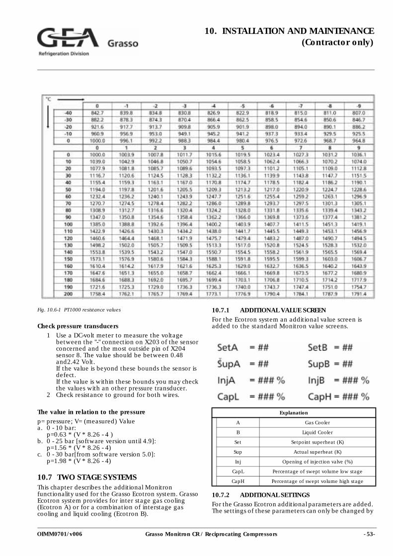
- 53-Grasso Monitron CR / Reciprocating Compressors
10. INSTALLATION AND MAINTENANCE(Contractor only)
OIMM0701/v006
Fig. 10.6-1 PT1000 resistance values
Check pressure transducers
1 Use a DC-volt meter to measure the voltage between the "-" connection on X203 of the sensor concerned and the most outside pin of X204 sensor 8. The value should be between 0.48 and2.42 Volt.If the value is beyond these bounds the sensor is defect.If the value is within these bounds you may check the values with an other pressure transducer.
2 Check resistance to ground for both wires.
The value in relation to the pressure
p= pressure; V= (measured) Valuea. 0 - 10 bar:
p=0.63 * (V * 8.26 - 4 ) b. 0 - 25 bar [software version until 4.9]:
p=1.56 * (V * 8.26 - 4) c. 0 - 30 bar[from software version 5.0]:
p=1.98 * (V * 8.26 - 4)
10.7 TWO STAGE SYSTEMSThis chapter describes the additional Monitron functionality used for the Grasso Ecotron system. Grasso Ecotron system provides for inter stage gas cooling (Ecotron A) or for a combination of interstage gas cooling and liquid cooling (Ecotron B).
10.7.1 ADDITIONAL VALUE SCREEN
For the Ecotron system an additional value screen is added to the standard Monitron value screens.
10.7.2 ADDITIONAL SETTINGSFor the Grasso Ecotron additional parameters are added. The settings of these parameters can only be changed by
Explanation
A Gas Cooler
B Liquid Cooler
Set Setpoint superheat (K)
Sup Actual superheat (K)
Inj Opening of injection valve (%)
CapL Percentage of swept volume low stage
CapH Percentage of swept volume high stage
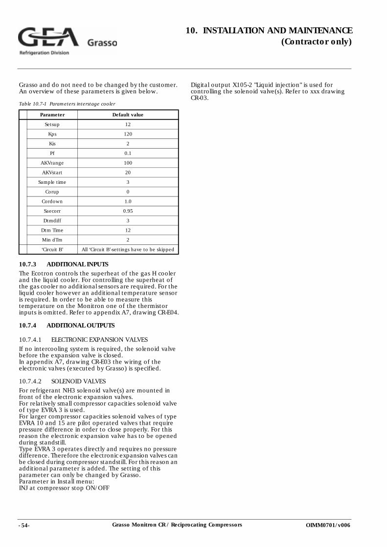
- 54- Grasso Monitron CR / Reciprocating Compressors
10. INSTALLATION AND MAINTENANCE(Contractor only)
OIMM0701/v006
Grasso and do not need to be changed by the customer. An overview of these parameters is given below.
Table 10.7-1 Parameters interstage cooler
10.7.3 ADDITIONAL INPUTSThe Ecotron controls the superheat of the gas H cooler and the liquid cooler. For controlling the superheat of the gas cooler no additional sensors are required. For the liquid cooler however an additional temperature sensor is required. In order to be able to measure this temperature on the Monitron one of the thermistor inputs is omitted. Refer to appendix A7, drawing CR-E04.
10.7.4 ADDITIONAL OUTPUTS
10.7.4.1 ELECTRONIC EXPANSION VALVES
If no intercooling system is required, the solenoid valve before the expansion valve is closed.In appendix A7, drawing CR-E03 the wiring of the electronic valves (executed by Grasso) is specified.
10.7.4.2 SOLENOID VALVES
For refrigerant NH3 solenoid valve(s) are mounted in front of the electronic expansion valves. For relatively small compressor capacities solenoid valve of type EVRA 3 is used. For larger compressor capacities solenoid valves of type EVRA 10 and 15 are pilot operated valves that require pressure difference in order to close properly. For this reason the electronic expansion valve has to be opened during standstill. Type EVRA 3 operates directly and requires no pressure difference. Therefore the electronic expansion valves can be closed during compressor standstill. For this reason an additional parameter is added. The setting of this parameter can only be changed by Grasso. Parameter in Install menu: INJ at compressor stop ON/OFF
Digital output X105-2 "Liquid injection" is used for controlling the solenoid valve(s). Refer to xxx drawing CR-03.
Parameter Default value
Setsup 12
Kps 120
Kis 2
Pf 0.1
AKVrange 100
AKVstart 20
Sample time 3
Corup 0
Cordown 1.0
Saecorr 0.95
Dtmdiff 3
Dtm Time 12
Min dTm 2
‘Circuit B’ All ‘Circuit B’-settings have to be skipped
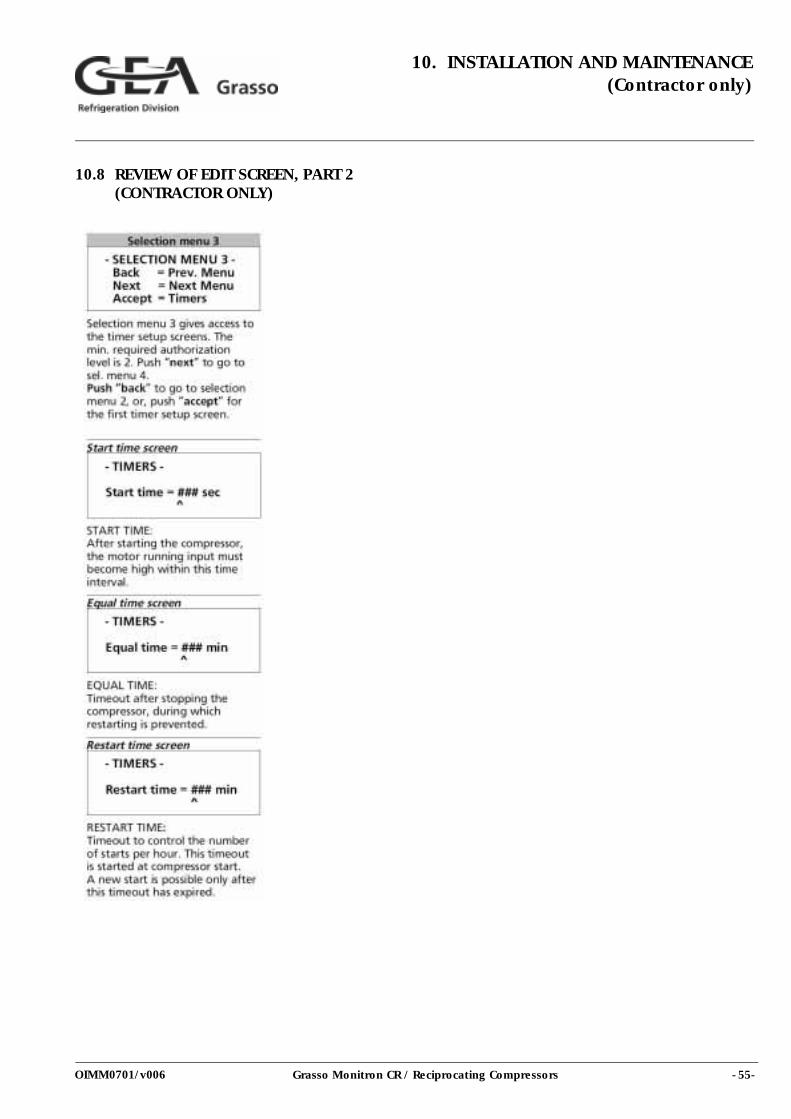
- 55-Grasso Monitron CR / Reciprocating Compressors
10. INSTALLATION AND MAINTENANCE(Contractor only)
OIMM0701/v006
10.8 REVIEW OF EDIT SCREEN, PART 2 (CONTRACTOR ONLY)
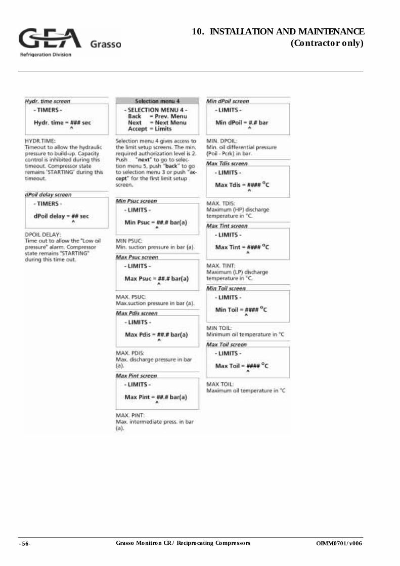
- 56- Grasso Monitron CR / Reciprocating Compressors
10. INSTALLATION AND MAINTENANCE(Contractor only)
OIMM0701/v006
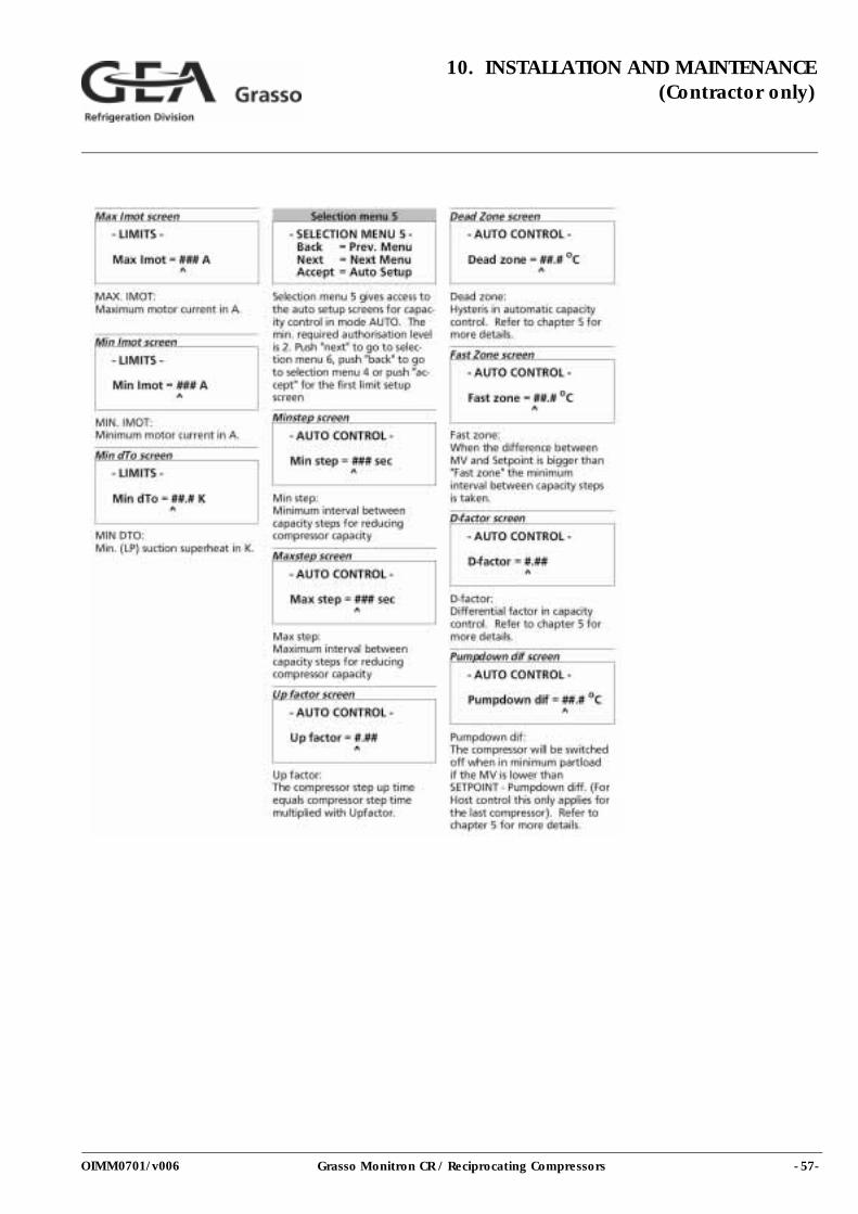
- 57-Grasso Monitron CR / Reciprocating Compressors
10. INSTALLATION AND MAINTENANCE(Contractor only)
OIMM0701/v006
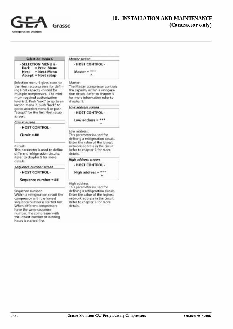
- 58- Grasso Monitron CR / Reciprocating Compressors
10. INSTALLATION AND MAINTENANCE(Contractor only)
OIMM0701/v006
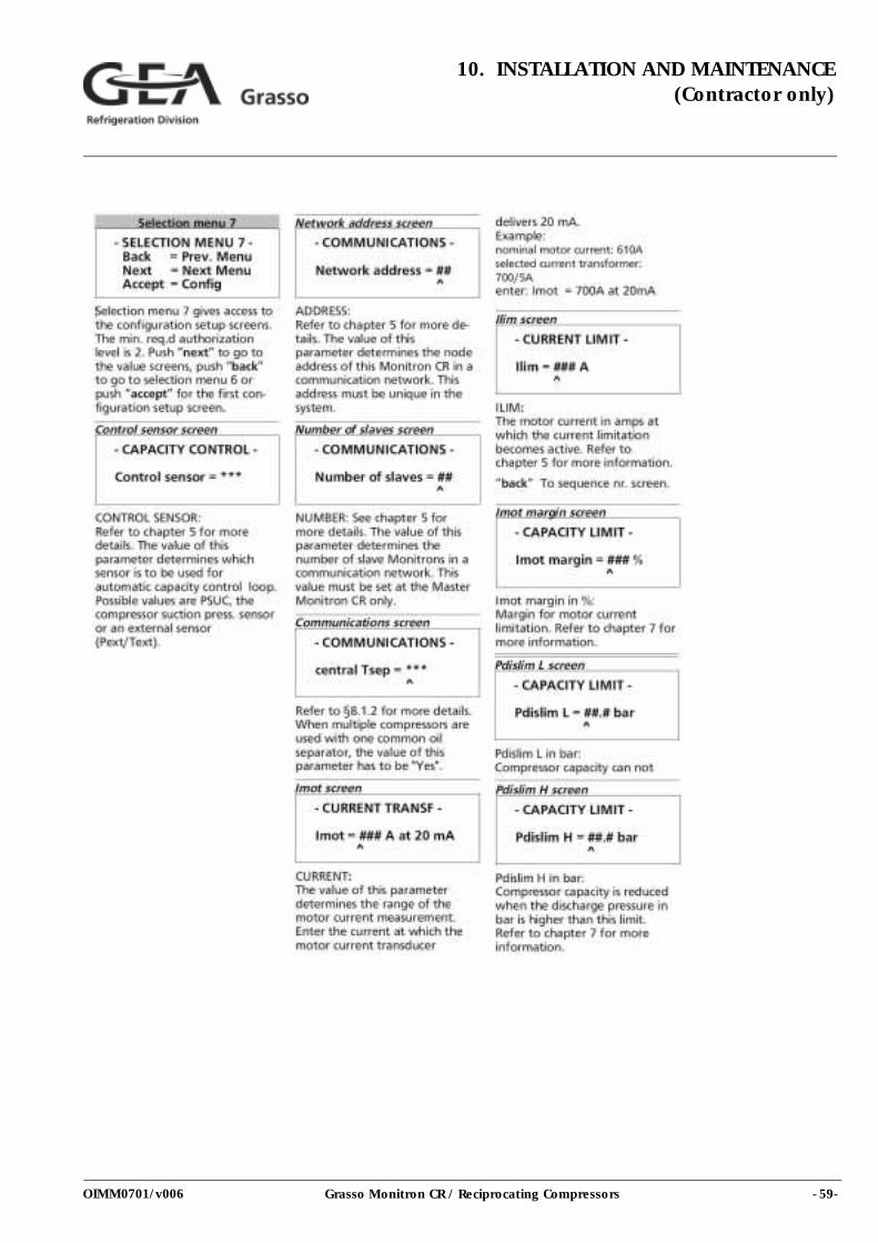
- 59-Grasso Monitron CR / Reciprocating Compressors
10. INSTALLATION AND MAINTENANCE(Contractor only)
OIMM0701/v006
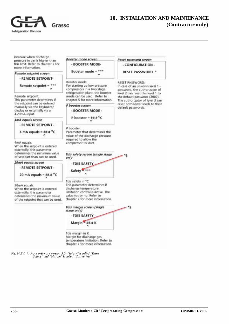
- 60- Grasso Monitron CR / Reciprocating Compressors
10. INSTALLATION AND MAINTENANCE(Contractor only)
OIMM0701/v006
Fig. 10.8-1 *) From software version 5.0, “Safety” is called “Extra Safety“ and “Margin“ is called “Correction“
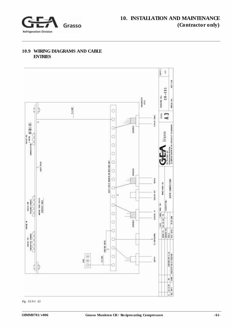
- 61-Grasso Monitron CR / Reciprocating Compressors
10. INSTALLATION AND MAINTENANCE(Contractor only)
OIMM0701/v006
10.9 WIRING DIAGRAMS AND CABLE ENTRIES
Fig. 10.9-1 E1
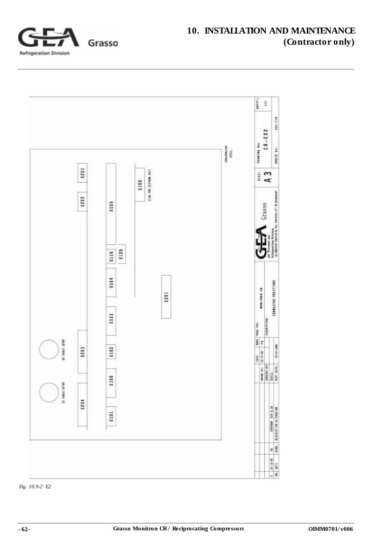
- 62- Grasso Monitron CR / Reciprocating Compressors
10. INSTALLATION AND MAINTENANCE(Contractor only)
OIMM0701/v006
Fig. 10.9-2 E2
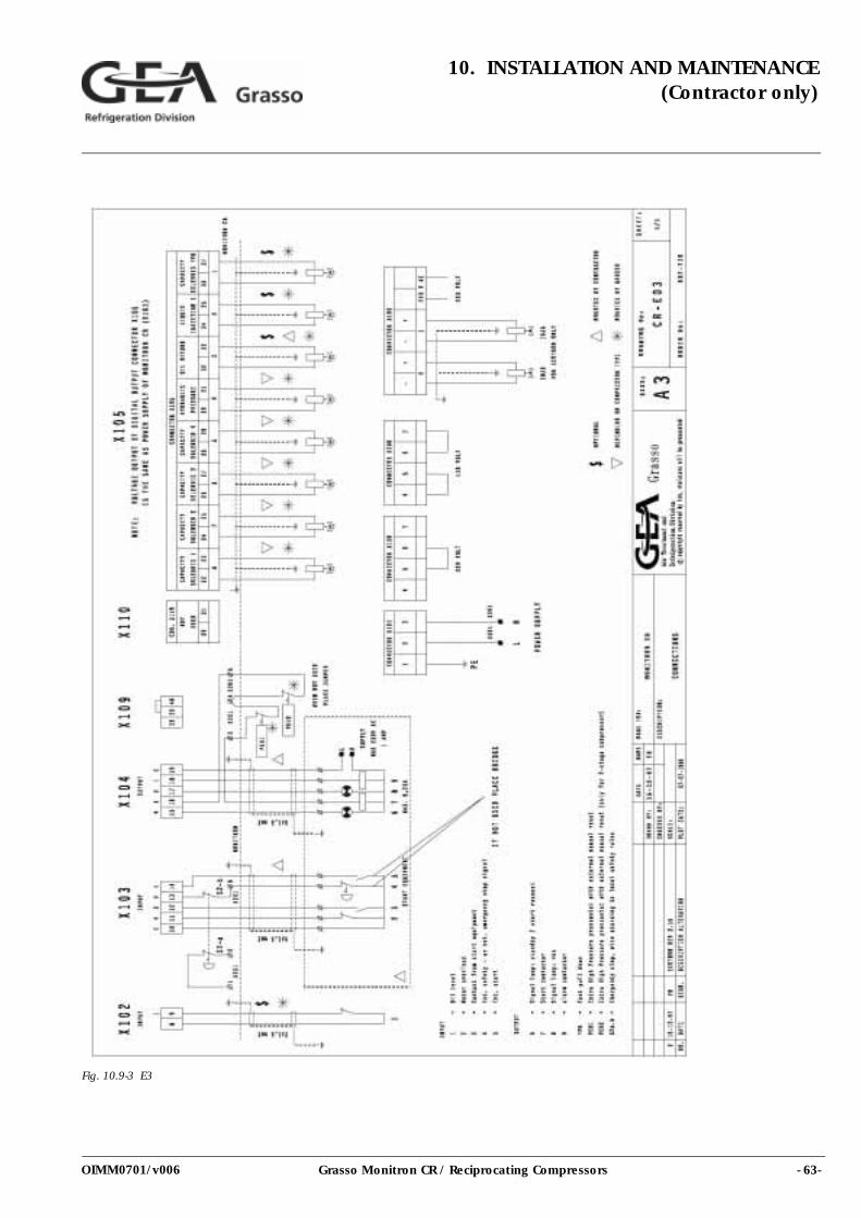
- 63-Grasso Monitron CR / Reciprocating Compressors
10. INSTALLATION AND MAINTENANCE(Contractor only)
OIMM0701/v006
Fig. 10.9-3 E3
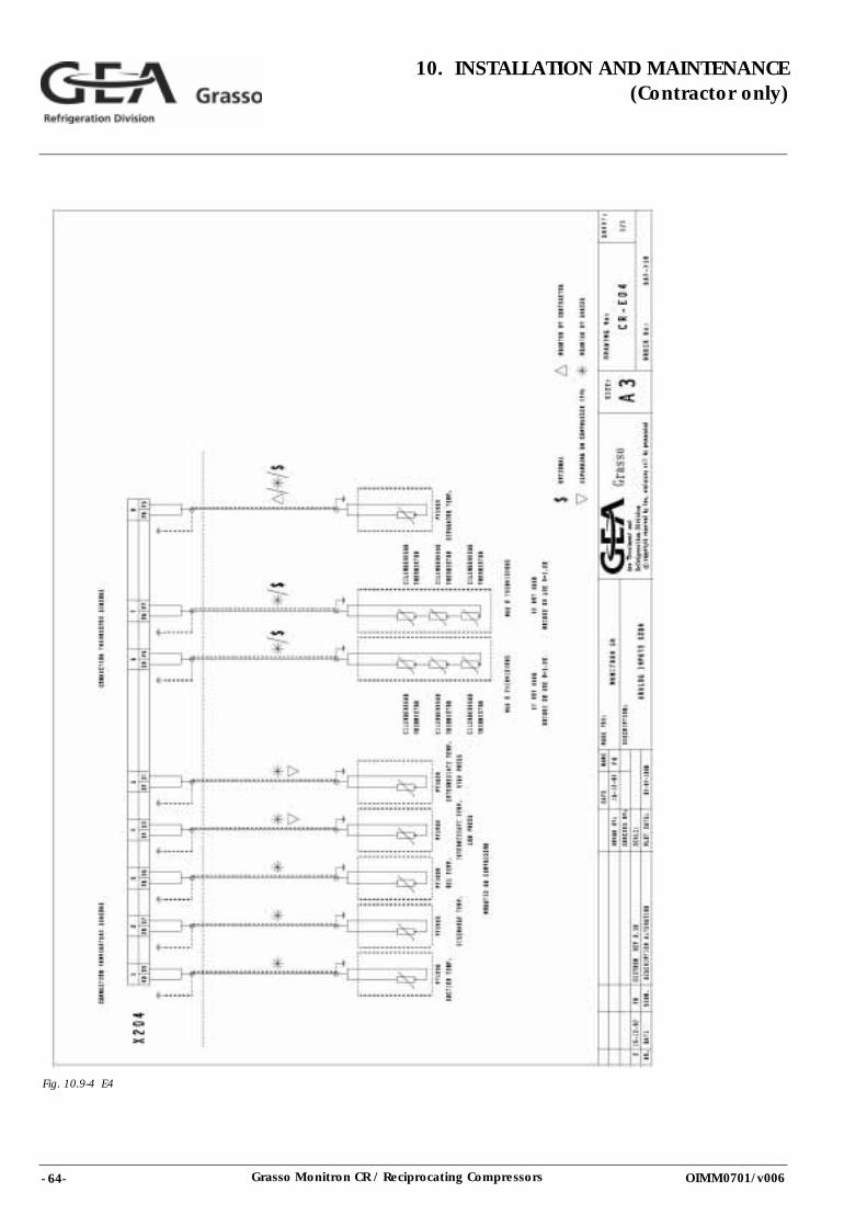
- 64- Grasso Monitron CR / Reciprocating Compressors
10. INSTALLATION AND MAINTENANCE(Contractor only)
OIMM0701/v006
Fig. 10.9-4 E4
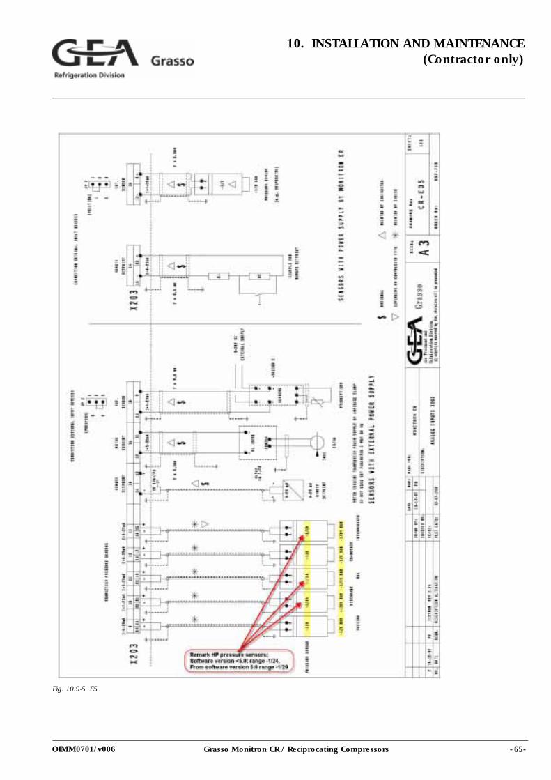
- 65-Grasso Monitron CR / Reciprocating Compressors
10. INSTALLATION AND MAINTENANCE(Contractor only)
OIMM0701/v006
Fig. 10.9-5 E5
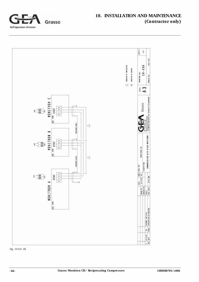
- 66- Grasso Monitron CR / Reciprocating Compressors
10. INSTALLATION AND MAINTENANCE(Contractor only)
OIMM0701/v006
Fig. 10.9-6 E6
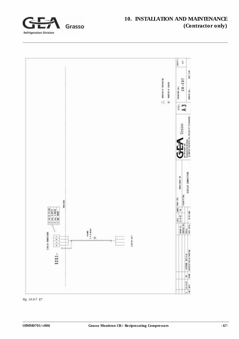
- 67-Grasso Monitron CR / Reciprocating Compressors
10. INSTALLATION AND MAINTENANCE(Contractor only)
OIMM0701/v006
Fig. 10.9-7 E7
- 68- Grasso Monitron CR / Reciprocating Compressors
10. INSTALLATION AND MAINTENANCE(Contractor only)
OIMM0701/v006
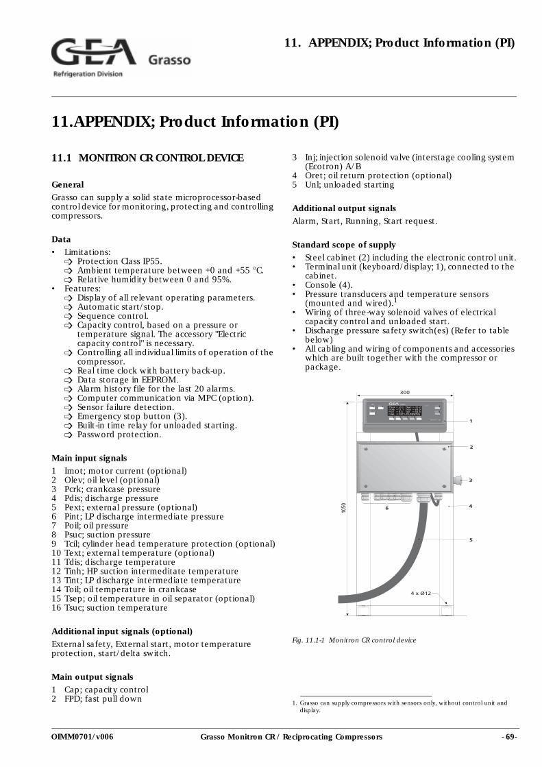
- 69-Grasso Monitron CR / Reciprocating Compressors
11. APPENDIX; Product Information (PI)
OIMM0701/v006
11.APPENDIX; Product Information (PI)
11.1 MONITRON CR CONTROL DEVICE
GeneralGrasso can supply a solid state microprocessor-based control device for monitoring, protecting and controlling compressors.
Data• Limitations:
Protection Class IP55.Ambient temperature between +0 and +55 °C.Relative humidity between 0 and 95%.
• Features:Display of all relevant operating parameters.Automatic start/stop.Sequence control.Capacity control, based on a pressure or temperature signal. The accessory "Electric capacity control" is necessary.Controlling all individual limits of operation of the compressor.Real time clock with battery back-up.Data storage in EEPROM.Alarm history file for the last 20 alarms.Computer communication via MPC (option).Sensor failure detection.Emergency stop button (3).Built-in time relay for unloaded starting.Password protection.
Main input signals1 Imot; motor current (optional)2 Olev; oil level (optional)3 Pcrk; crankcase pressure4 Pdis; discharge pressure5 Pext; external pressure (optional)6 Pint; LP discharge intermediate pressure7 Poil; oil pressure8 Psuc; suction pressure9 Tcil; cylinder head temperature protection (optional)10 Text; external temperature (optional)11 Tdis; discharge temperature12 Tinh; HP suction intermeditate temperature13 Tint; LP discharge intermediate temperature14 Toil; oil temperature in crankcase15 Tsep; oil temperature in oil separator (optional)16 Tsuc; suction temperature
Additional input signals (optional)External safety, External start, motor temperature protection, start/delta switch.
Main output signals1 Cap; capacity control2 FPD; fast pull down
3 Inj; injection solenoid valve (interstage cooling system (Ecotron) A/B
4 Oret; oil return protection (optional)5 Unl; unloaded starting
Additional output signalsAlarm, Start, Running, Start request.
Standard scope of supply• Steel cabinet (2) including the electronic control unit.• Terminal unit (keyboard/display; 1), connected to the
cabinet.• Console (4).• Pressure transducers and temperature sensors
(mounted and wired).1
• Wiring of three-way solenoid valves of electrical capacity control and unloaded start.
• Discharge pressure safety switch(es) (Refer to table below)
• All cabling and wiring of components and accessories which are built together with the compressor or package.
Fig. 11.1-1 Monitron CR control device
1. Grasso can supply compressors with sensors only, without control unit and display.
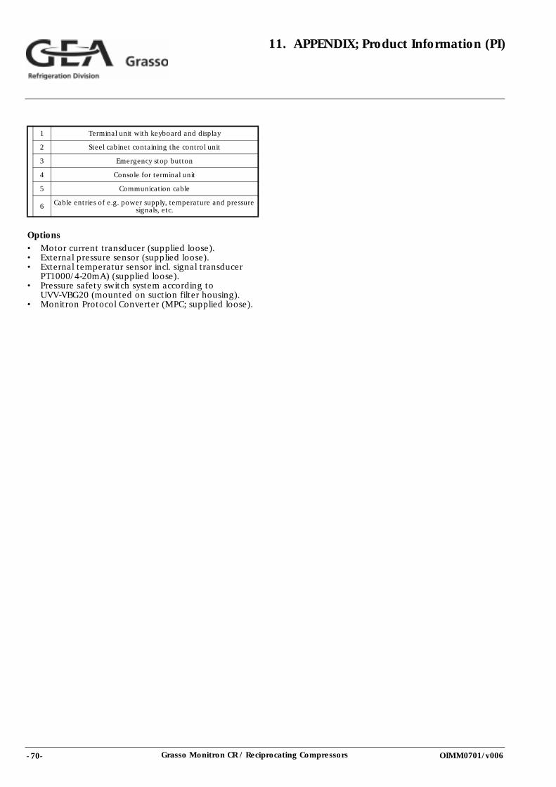
- 70- Grasso Monitron CR / Reciprocating Compressors
11. APPENDIX; Product Information (PI)
OIMM0701/v006
Options• Motor current transducer (supplied loose).• External pressure sensor (supplied loose).• External temperatur sensor incl. signal transducer
PT1000/4-20mA) (supplied loose).• Pressure safety switch system according to
UVV-VBG20 (mounted on suction filter housing).• Monitron Protocol Converter (MPC; supplied loose).
1 Terminal unit with keyboard and display
2 Steel cabinet containing the control unit
3 Emergency stop button
4 Console for terminal unit
5 Communication cable
6 Cable entries of e.g. power supply, temperature and pressure signals, etc.
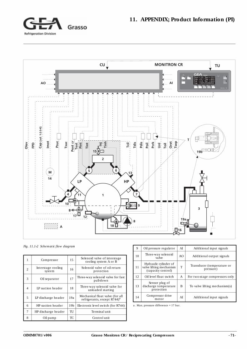
- 71-Grasso Monitron CR / Reciprocating Compressors
11. APPENDIX; Product Information (PI)
OIMM0701/v006
Fig. 11.1-2 Schematic flow diagram
1 Compressor 15 Solenoid valve of interstage cooling system A or B
2 Interstage cooling system 16 Solenoid valve of oil return
protection
3 Oil separator 17 Three-way solenoid valve for fast pull-down
4 LP suction header 18 Three-way solenoid valve for unloaded starting
5 LP discharge header 19a Mechanical float valve (for all refrigerants, except R744)a
6 HP suction header 19b Electronic level switch (for R744)
7 HP discharge header TU Terminal unit
8 Oil pump TC Control unit
9 Oil pressure regulator AI Additional input signals
10 Three-way solenoid valve AO Additional output signals
11Hydraulic cylinder of
valve lifting mechanism (capacity control)
T Transducer (temperature or pressure)
12 Oil level float switch A For two-stage compressors only
13Sensor plug of
discharge temperature protection
B To valve lifting mechanism(s)
14 Compressor drive motor AI Additional input signals
a. Max. pressure difference = 17 bar.
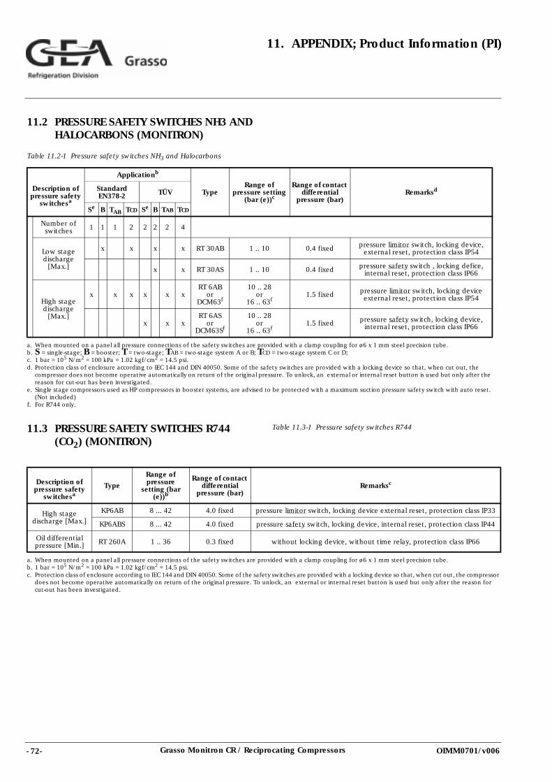
- 72- Grasso Monitron CR / Reciprocating Compressors
11. APPENDIX; Product Information (PI)
OIMM0701/v006
11.2 PRESSURE SAFETY SWITCHES NH3 AND HALOCARBONS (MONITRON)
Table 11.2-1 Pressure safety switches NH3 and Halocarbons
11.3 PRESSURE SAFETY SWITCHES R744 (CO2) (MONITRON)
Table 11.3-1 Pressure safety switches R744
Description of pressure safety
switchesa
Applicationb
TypeRange of
pressure setting (bar (e))c
Range of contact differential
pressure (bar)RemarksdStandard
EN378-2 TÜV
Se B TAB TCD Se B TAB TCD
Number of switches 1 1 1 2 2 2 2 4
Low stage discharge
[Max.]
x x x x RT 30AB 1 .. 10 0.4 fixed pressure limitor switch, locking device, external reset, protection class IP54
x x RT 30AS 1 .. 10 0.4 fixed pressure safety switch , locking defice, internal reset, protection class IP66
High stage discharge
[Max.]
x x x x x xRT 6AB
orDCM63f
10 .. 28or
16 .. 63f1.5 fixed pressure limitor switch, locking device
external reset, protection class IP54
x x xRT 6AS
orDCM63Sf
10 .. 28or
16 .. 63f1.5 fixed pressure safety switch, locking device,
internal reset, protection class IP66
a. When mounted on a panel all pressure connections of the safety switches are provided with a clamp coupling for ø6 x 1 mm steel precision tube.b. S = single-stage; B = booster; T = two-stage; TAB = two-stage system A or B; TCD = two-stage system C or D;c. 1 bar = 105 N/m2 = 100 kPa = 1.02 kgf/cm2 = 14.5 psi.d. Protection class of enclosure according to IEC 144 and DIN 40050. Some of the safety switches are provided with a locking device so that, when cut out, the
compressor does not become operative automatically on return of the original pressure. To unlock, an external or internal reset button is used but only after the reason for cut-out has been investigated.
e. Single stage compressors used as HP compressors in booster systems, are advised to be protected with a maximum suction pressure safety switch with auto reset. (Not included)
f. For R744 only.
Description of pressure safety
switchesaType
Range of pressure
setting (bar (e))b
Range of contact differential
pressure (bar)Remarksc
High stage discharge [Max.]
KP6AB 8 ... 42 4.0 fixed pressure limitor switch, locking device external reset, protection class IP33
KP6ABS 8 ... 42 4.0 fixed pressure safety switch, locking device, internal reset, protection class IP44
Oil differential pressure [Min.] RT 260A 1 .. 36 0.3 fixed without locking device, without time relay, protection class IP66
a. When mounted on a panel all pressure connections of the safety switches are provided with a clamp coupling for ø6 x 1 mm steel precision tube.b. 1 bar = 105 N/m2 = 100 kPa = 1.02 kgf/cm2 = 14.5 psi.c. Protection class of enclosure according to IEC 144 and DIN 40050. Some of the safety switches are provided with a locking device so that, when cut out, the compressor
does not become operative automatically on return of the original pressure. To unlock, an external or internal reset button is used but only after the reason for cut-out has been investigated.
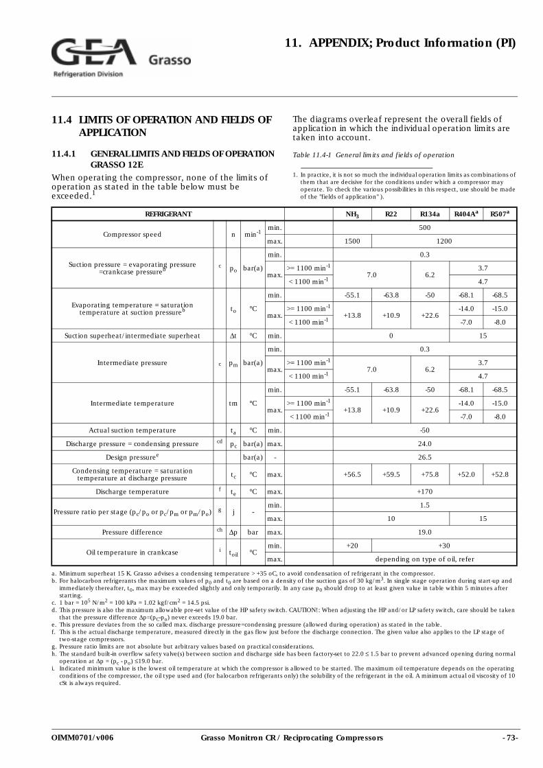
- 73-Grasso Monitron CR / Reciprocating Compressors
11. APPENDIX; Product Information (PI)
OIMM0701/v006
11.4 LIMITS OF OPERATION AND FIELDS OF APPLICATION
11.4.1 GENERAL LIMITS AND FIELDS OF OPERATION GRASSO 12E
When operating the compressor, none of the limits of operation as stated in the table below must be exceeded.1
The diagrams overleaf represent the overall fields of application in which the individual operation limits are taken into account.
Table 11.4-1 General limits and fields of operation
1. In practice, it is not so much the individual operation limits as combinations of them that are decisive for the conditions under which a compressor may operate. To check the various possibilities in this respect, use should be made of the "fields of application" ).
REFRIGERANT NH3 R22 R134a R404Aa R507a
Compressor speed n min-1min. 500
max. 1500 1200
Suction pressure = evaporating pressure =crankcase pressureb
c po bar(a)
min. 0.3
max.>= 1100 min-1
7.0 6.23.7
< 1100 min-1 4.7
Evaporating temperature = saturation temperature at suction pressureb to °C
min. -55.1 -63.8 -50 -68.1 -68.5
max.>= 1100 min-1
+13.8 +10.9 +22.6-14.0 -15.0
< 1100 min-1 -7.0 -8.0
Suction superheat/intermediate superheat ∆t °C min. 0 15
Intermediate pressure c pm bar(a)
min. 0.3
max.>= 1100 min-1
7.0 6.23.7
< 1100 min-1 4.7
Intermediate temperature tm °C
min. -55.1 -63.8 -50 -68.1 -68.5
max.>= 1100 min-1
+13.8 +10.9 +22.6-14.0 -15.0
< 1100 min-1 -7.0 -8.0
Actual suction temperature ta °C min. -50
Discharge pressure = condensing pressure cd pc bar(a) max. 24.0
Design pressuree bar(a) - 26.5
Condensing temperature = saturation temperature at discharge pressure tc °C max. +56.5 +59.5 +75.8 +52.0 +52.8
Discharge temperature f te °C max. +170
Pressure ratio per stage (pc/po or pc/pm or pm/po) g j -min. 1.5
max. 10 15
Pressure difference ch ∆p bar max. 19.0
Oil temperature in crankcase i toil °Cmin. +20 +30
max. depending on type of oil, refer
a. Minimum superheat 15 K. Grasso advises a condensing temperature > +35 oC, to avoid condensation of refrigerant in the compressor.b. For halocarbon refrigerants the maximum values of p0 and t0 are based on a density of the suction gas of 30 kg/m3. In single stage operation during start-up and
immediately thereafter, t0, max may be exceeded slightly and only temporarily. In any case p0 should drop to at least given value in table within 5 minutes after starting.
c. 1 bar = 105 N/m2 = 100 kPa = 1.02 kgf/cm2 = 14.5 psi.d. This pressure is also the maximum allowable pre-set value of the HP safety switch. CAUTION!: When adjusting the HP and/or LP safety switch, care should be taken
that the pressure difference ∆p=(pC-po) never exceeds 19.0 bar.e. This pressure deviates from the so called max. discharge pressure=condensing pressure (allowed during operation) as stated in the table.f. This is the actual discharge temperature, measured directly in the gas flow just before the discharge connection. The given value also applies to the LP stage of
two-stage compressors.g. Pressure ratio limits are not absolute but arbitrary values based on practical considerations.h. The standard built-in overflow safety valve(s) between suction and discharge side has been factory-set to 22.0 ≤ 1.5 bar to prevent advanced opening during normal
operation at ∆p = (pc - po) ≤19.0 bar.i. Indicated minimum value is the lowest oil temperature at which the compressor is allowed to be started. The maximum oil temperature depends on the operating
conditions of the compressor, the oil type used and (for halocarbon refrigerants only) the solubility of the refrigerant in the oil. A minimum actual oil viscosity of 10 cSt is always required.
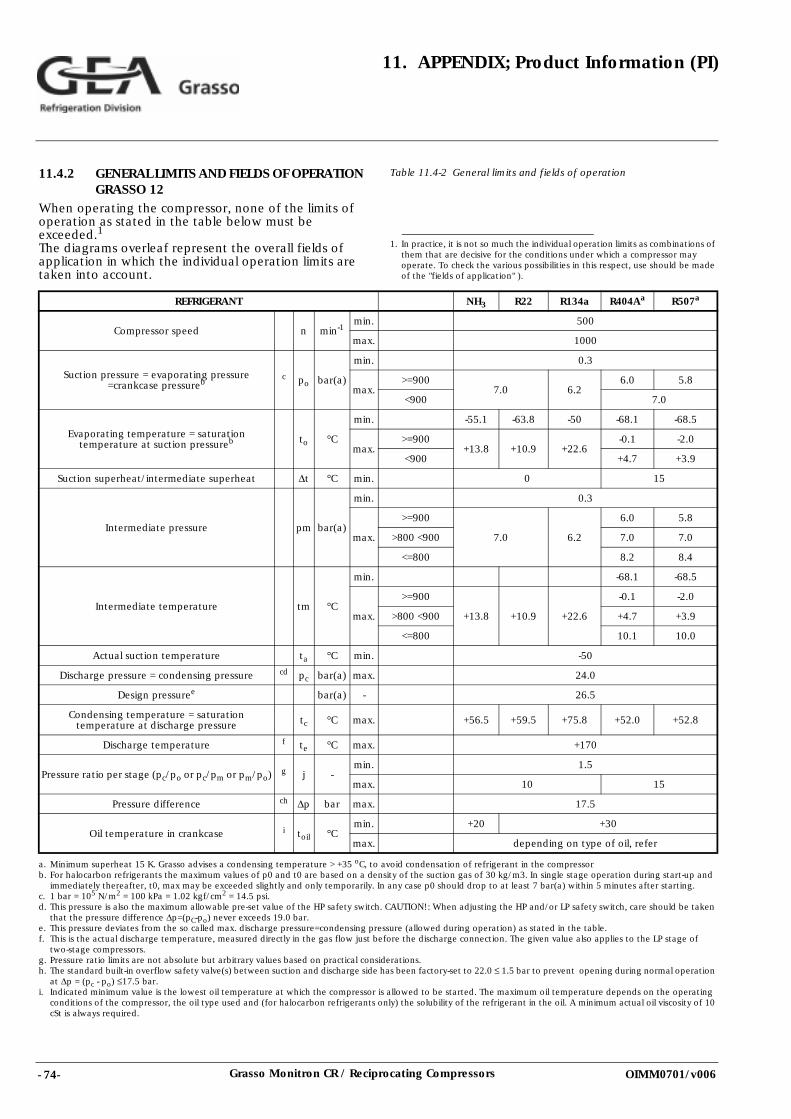
- 74- Grasso Monitron CR / Reciprocating Compressors
11. APPENDIX; Product Information (PI)
OIMM0701/v006
11.4.2 GENERAL LIMITS AND FIELDS OF OPERATION GRASSO 12
When operating the compressor, none of the limits of operation as stated in the table below must be exceeded.1
The diagrams overleaf represent the overall fields of application in which the individual operation limits are taken into account.
Table 11.4-2 General limits and fields of operation
1. In practice, it is not so much the individual operation limits as combinations of them that are decisive for the conditions under which a compressor may operate. To check the various possibilities in this respect, use should be made of the "fields of application" ).
REFRIGERANT NH3 R22 R134a R404Aa R507a
Compressor speed n min-1min. 500
max. 1000
Suction pressure = evaporating pressure =crankcase pressureb
c po bar(a)
min. 0.3
max.>=900
7.0 6.26.0 5.8
<900 7.0
Evaporating temperature = saturation temperature at suction pressureb to °C
min. -55.1 -63.8 -50 -68.1 -68.5
max.>=900
+13.8 +10.9 +22.6-0.1 -2.0
<900 +4.7 +3.9
Suction superheat/intermediate superheat ∆t °C min. 0 15
Intermediate pressure pm bar(a)
min. 0.3
max.
>=900
7.0 6.2
6.0 5.8
>800 <900 7.0 7.0
<=800 8.2 8.4
Intermediate temperature tm °C
min. -68.1 -68.5
max.
>=900
+13.8 +10.9 +22.6
-0.1 -2.0
>800 <900 +4.7 +3.9
<=800 10.1 10.0
Actual suction temperature ta °C min. -50
Discharge pressure = condensing pressure cd pc bar(a) max. 24.0
Design pressuree bar(a) - 26.5
Condensing temperature = saturation temperature at discharge pressure tc °C max. +56.5 +59.5 +75.8 +52.0 +52.8
Discharge temperature f te °C max. +170
Pressure ratio per stage (pc/po or pc/pm or pm/po) g j -min. 1.5
max. 10 15
Pressure difference ch ∆p bar max. 17.5
Oil temperature in crankcase i toil °Cmin. +20 +30
max. depending on type of oil, refer
a. Minimum superheat 15 K. Grasso advises a condensing temperature > +35 oC, to avoid condensation of refrigerant in the compressorb. For halocarbon refrigerants the maximum values of p0 and t0 are based on a density of the suction gas of 30 kg/m3. In single stage operation during start-up and
immediately thereafter, t0, max may be exceeded slightly and only temporarily. In any case p0 should drop to at least 7 bar(a) within 5 minutes after starting.c. 1 bar = 105 N/m2 = 100 kPa = 1.02 kgf/cm2 = 14.5 psi.d. This pressure is also the maximum allowable pre-set value of the HP safety switch. CAUTION!: When adjusting the HP and/or LP safety switch, care should be taken
that the pressure difference ∆p=(pC-po) never exceeds 19.0 bar.e. This pressure deviates from the so called max. discharge pressure=condensing pressure (allowed during operation) as stated in the table.f. This is the actual discharge temperature, measured directly in the gas flow just before the discharge connection. The given value also applies to the LP stage of
two-stage compressors.g. Pressure ratio limits are not absolute but arbitrary values based on practical considerations.h. The standard built-in overflow safety valve(s) between suction and discharge side has been factory-set to 22.0 ≤ 1.5 bar to prevent opening during normal operation
at ∆p = (pc - po) ≤17.5 bar.i. Indicated minimum value is the lowest oil temperature at which the compressor is allowed to be started. The maximum oil temperature depends on the operating
conditions of the compressor, the oil type used and (for halocarbon refrigerants only) the solubility of the refrigerant in the oil. A minimum actual oil viscosity of 10 cSt is always required.
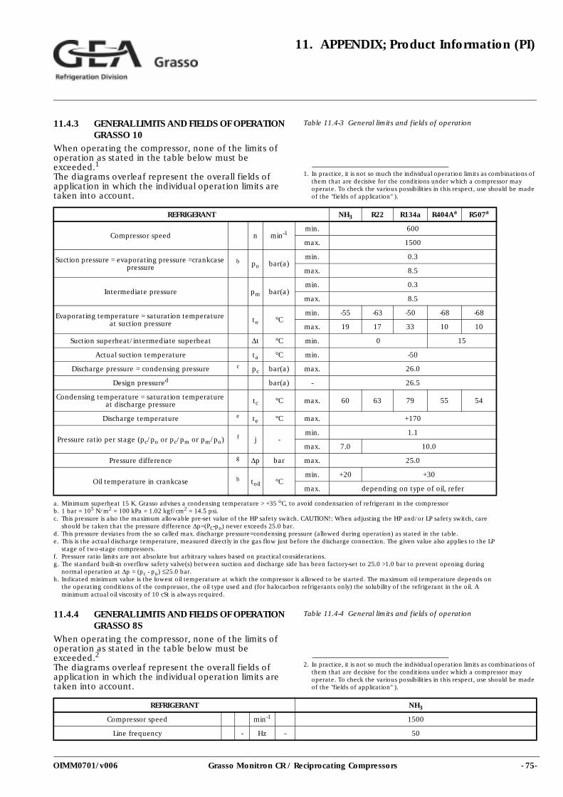
- 75-Grasso Monitron CR / Reciprocating Compressors
11. APPENDIX; Product Information (PI)
OIMM0701/v006
11.4.3 GENERAL LIMITS AND FIELDS OF OPERATION GRASSO 10
When operating the compressor, none of the limits of operation as stated in the table below must be exceeded.1
The diagrams overleaf represent the overall fields of application in which the individual operation limits are taken into account.
Table 11.4-3 General limits and fields of operation
11.4.4 GENERAL LIMITS AND FIELDS OF OPERATION GRASSO 8S
When operating the compressor, none of the limits of operation as stated in the table below must be exceeded.2
The diagrams overleaf represent the overall fields of application in which the individual operation limits are taken into account.
Table 11.4-4 General limits and fields of operation
1. In practice, it is not so much the individual operation limits as combinations of them that are decisive for the conditions under which a compressor may operate. To check the various possibilities in this respect, use should be made of the "fields of application" ).
REFRIGERANT NH3 R22 R134a R404Aa R507a
Compressor speed n min-1min. 600
max. 1500
Suction pressure = evaporating pressure =crankcase pressure
b po bar(a)min. 0.3
max. 8.5
Intermediate pressure pm bar(a)min. 0.3
max. 8.5
Evaporating temperature = saturation temperature at suction pressure to °C
min. -55 -63 -50 -68 -68
max. 19 17 33 10 10
Suction superheat/intermediate superheat ∆t °C min. 0 15
Actual suction temperature ta °C min. -50
Discharge pressure = condensing pressure c pc bar(a) max. 26.0
Design pressured bar(a) - 26.5
Condensing temperature = saturation temperature at discharge pressure tc °C max. 60 63 79 55 54
Discharge temperature e te °C max. +170
Pressure ratio per stage (pc/po or pc/pm or pm/po) f j -min. 1.1
max. 7.0 10.0
Pressure difference g ∆p bar max. 25.0
Oil temperature in crankcase h toil °Cmin. +20 +30
max. depending on type of oil, refer
a. Minimum superheat 15 K. Grasso advises a condensing temperature > +35 oC, to avoid condensation of refrigerant in the compressorb. 1 bar = 105 N/m2 = 100 kPa = 1.02 kgf/cm2 = 14.5 psi.c. This pressure is also the maximum allowable pre-set value of the HP safety switch. CAUTION!: When adjusting the HP and/or LP safety switch, care
should be taken that the pressure difference ∆p=(PC-po) never exceeds 25.0 bar.d. This pressure deviates from the so called max. discharge pressure=condensing pressure (allowed during operation) as stated in the table.e. This is the actual discharge temperature, measured directly in the gas flow just before the discharge connection. The given value also applies to the LP
stage of two-stage compressors.f. Pressure ratio limits are not absolute but arbitrary values based on practical considerations.g. The standard built-in overflow safety valve(s) between suction and discharge side has been factory-set to 25.0 >1.0 bar to prevent opening during
normal operation at ∆p = (pc - po) ≤25.0 bar.h. Indicated minimum value is the lowest oil temperature at which the compressor is allowed to be started. The maximum oil temperature depends on
the operating conditions of the compressor, the oil type used and (for halocarbon refrigerants only) the solubility of the refrigerant in the oil. A minimum actual oil viscosity of 10 cSt is always required.
2. In practice, it is not so much the individual operation limits as combinations of them that are decisive for the conditions under which a compressor may operate. To check the various possibilities in this respect, use should be made of the "fields of application" ).
REFRIGERANT NH3
Compressor speed min-1 1500
Line frequency - Hz - 50
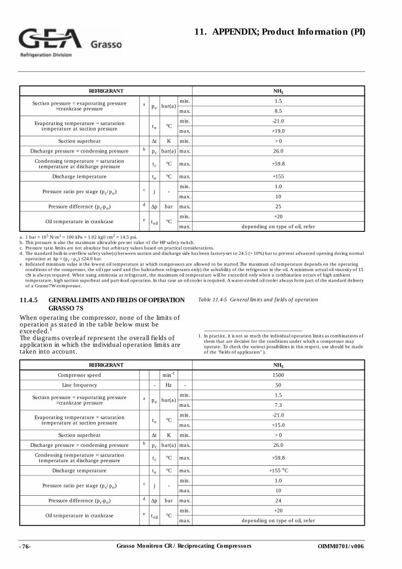
- 76- Grasso Monitron CR / Reciprocating Compressors
11. APPENDIX; Product Information (PI)
OIMM0701/v006
11.4.5 GENERAL LIMITS AND FIELDS OF OPERATION GRASSO 7S
When operating the compressor, none of the limits of operation as stated in the table below must be exceeded.1
The diagrams overleaf represent the overall fields of application in which the individual operation limits are taken into account.
Table 11.4-5 General limits and fields of operation
Suction pressure = evaporating pressure =crankcase pressure
a po bar(a)min. 1.5
max. 8.5
Evaporating temperature = saturation temperature at suction pressure to °C
min. -21.0
max. +19.0
Suction superheat ∆t K min. > 0
Discharge pressure = condensing pressure b pc bar(a) max. 26.0
Condensing temperature = saturation temperature at discharge pressure tc °C max. +59.8
Discharge temperature te °C max. +155
Pressure ratio per stage (pc/po) c j -min. 1.0
max. 10
Pressure difference (pc-po) d ∆p bar max. 25
Oil temperature in crankcase e toil °Cmin. +20
max. depending on type of oil, refer
a. 1 bar = 105 N/m2 = 100 kPa = 1.02 kgf/cm2 = 14.5 psi.b. This pressure is also the maximum allowable pre-set value of the HP safety switch.c. Pressure ratio limits are not absolute but arbitrary values based on practical considerations.d. The standard built-in overflow safety valve(s) between suction and discharge side has been factory-set to 24.5 (+ 10%) bar to prevent advanced opening during normal
operation at ∆p = (pc - po) ≤24.0 bar.e. Indicated minimum value is the lowest oil temperature at which compressors are allowed to be started.The maximum oil temperature depends on the operating
conditions of the compressor, the oil type used and (for halocarbon refrigerants only) the solvability of the refrigerant in the oil. A minimum actual oil viscosity of 15 cSt is always required. When using ammonia as refrigerant, the maximum oil temperature will be exceeded only when a combination occurs of high ambient temperature, high suction superheat and part-load operation. In that case an oil cooler is required. A water-cooled oil cooler always form part of the standard delivery of a Grasso7W-compressor.
REFRIGERANT NH3
1. In practice, it is not so much the individual operation limits as combinations of them that are decisive for the conditions under which a compressor may operate. To check the various possibilities in this respect, use should be made of the "fields of application" ).
REFRIGERANT NH3
Compressor speed min-1 1500
Line frequency - Hz - 50
Suction pressure = evaporating pressure =crankcase pressure
a po bar(a)min. 1.5
max. 7.3
Evaporating temperature = saturation temperature at suction pressure to °C
min. -21.0
max. +15.0
Suction superheat ∆t K min. > 0
Discharge pressure = condensing pressure b pc bar(a) max. 26.0
Condensing temperature = saturation temperature at discharge pressure tc °C max. +59.8
Discharge temperature te °C max. +155 oC
Pressure ratio per stage (pc/po) c j -min. 1.0
max. 10
Pressure difference (pc-po) d ∆p bar max. 24
Oil temperature in crankcase e toil °Cmin. +20
max. depending on type of oil, refer
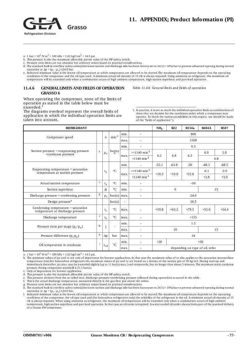
- 77-Grasso Monitron CR / Reciprocating Compressors
11. APPENDIX; Product Information (PI)
OIMM0701/v006
11.4.6 GENERAL LIMITS AND FIELDS OF OPERATION GRASSO 6
When operating the compressor, none of the limits of operation as stated in the table below must be exceeded.1
The diagrams overleaf represent the overall fields of application in which the individual operation limits are taken into account.
Table 11.4-6 General limits and fields of operation
a. 1 bar = 105 N/m2 = 100 kPa = 1.02 kgf/cm2 = 14.5 psi.b. This pressure is also the maximum allowable pre-set value of the HP safety switch.c. Pressure ratio limits are not absolute but arbitrary values based on practical considerations.d. The standard built-in overflow safety valve(s) between suction and discharge side has been factory-set to 24.5 (+ 10%) bar to prevent advanced opening during normal
operation at ∆p = (pc - po) ≤24.0 bar.e. Indicated minimum value is the lowest oil temperature at which compressors are allowed to be started.The maximum oil temperature depends on the operating
conditions of the compressor and the oil type used. A minimum actual oil viscosity of 15 cSt is always required. Using ammonia as refrigerant, the maximum oil temperature will be exceeded only when a combination occurs of high ambient temperature, high suction superheat and part-load operation.
1. In practice, it is not so much the individual operation limits as combinations of them that are decisive for the conditions under which a compressor may operate. To check the various possibilities in this respect, use should be made of the "fields of application" ).
REFRIGERANT NH3 R22 R134a R404A R507
Compressor speed n min-1min. - 800
max. - 1500
Suction pressure = evaporating pressure =crankcase pressure
a pobar(a)
b
min. - 0.3
max.>=1140 min-1
6.2 6.8 6.26.0 5.8
<1140 min-1 6.8
Evaporating temperature = saturation temperature at suction pressure to °C
min. - -55.1 -63.8 -50 -68.1 -68.5
max.>=1140 min-1
+10.2 +10.0 +22.6-0.1 -2.0
<1140 min-1 +3.8 +3.0
Actual suction temperature c ta °C min. - -50
Suction superheat ∆t °C min. - 0 15
Discharge pressure = condensing pressure d pc bar(a) max. - 24.0
Design pressuree bar(a) - 26.5
Condensing temperature = saturation temperature at discharge pressure tc °C max. - +59.8 +63.2 +79.5 +55.6 +54.4
Discharge temperature f te °C max. - +155
Pressure ratio per stage (pc/po) g j -min. - 1.5
max. - 10 15
Pressure difference (pc-po) h ∆p bar max. - 24
Oil temperature in crankcase i toil °Cmin. - +20 +30
max. - depending on type of oil, refer
a. 1 bar = 105 N/m2 = 100 kPa = 1.02 kgf/cm2 = 14.5 psi.b. The minimum values of po and to are only of importance for booster applications. In that case the maximum value of to also applies to the saturation intermediate
temperature (tm).For halocarbon refrigerants the maximum values of po and to are based on a density of the suction gas of 30 kg/m3. During start-up and immediately thereafter, po,max. may be exceeded slightly [up to 11 bar(a) max.] and temporarily, but no longer than about 5 minutes. The maximum static crankcase pressure during compressor standstill is 21.5 bar(a).
c. Only of importance for booster application.d. This pressure is also the maximum allowable pre-set value of the HP safety switch.e. This pressure deviates from the so called max. discharge pressure=condensing pressure (allowed during operation) as stated in the table.f. This is the actual discharge temperature, measured directly in the gas flow just above the valves.g. Pressure ratio limits are not absolute but arbitrary values based on practical considerations.h. The standard built-in overflow safety valve(s) between suction and discharge side has been factory-set to 24.5 (+ 10%) bar to prevent advanced opening during normal
operation at ∆p = (pc - po) ≤24.0 bar.i. Indicated minimum value is the lowest oil temperature at which compressors are allowed to be started.The maximum oil temperature depends on the operating
conditions of the compressor, the oil type used and (for halocarbon refrigerants only) the solubility of the refrigerant in the oil. A minimum actual oil viscosity of 15 cSt is always required. When using ammonia as refrigerant, the maximum oil temperature will be exceeded only when a combination occurs of high ambient temperature, high suction superheat and part-load operation. In that case an oil cooler is required. A water-cooled oil cooler always forms part of the standard delivery of a Grasso 6W-compressor.
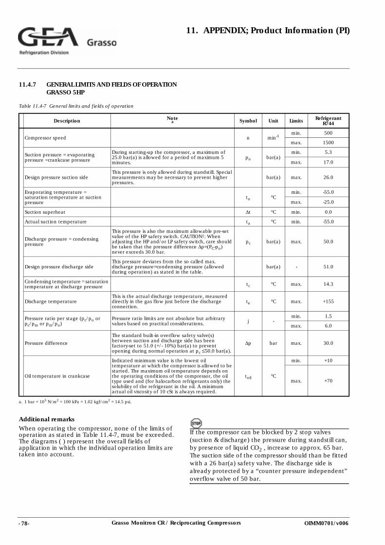
- 78- Grasso Monitron CR / Reciprocating Compressors
11. APPENDIX; Product Information (PI)
OIMM0701/v006
11.4.7 GENERAL LIMITS AND FIELDS OF OPERATION GRASSO 5HP
Table 11.4-7 General limits and fields of operation
Additional remarks
When operating the compressor, none of the limits of operation as stated in Table 11.4-7, must be exceeded.The diagrams ( ) represent the overall fields of application in which the individual operation limits are taken into account.
If the compressor can be blocked by 2 stop valves (suction & discharge) the pressure during standstill can, by presence of liquid CO2 , increase to approx. 65 bar. The suction side of the compressor should than be fitted with a 26 bar(a) safety valve. The discharge side is already protected by a “counter pressure independent” overflow valve of 50 bar.
Description Notea Symbol Unit Limits Refrigerant
R744
Compressor speed n min-1min. 500
max. 1500
Suction pressure = evaporating pressure =crankcase pressure
During starting-up the compressor, a maximum of 25.0 bar(a) is allowed for a period of maximum 5 minutes.
po bar(a)min. 5.3
max. 17.0
Design pressure suction sideThis pressure is only allowed during standstill. Special measurements may be necessary to prevent higher pressures.
bar(a) max. 26.0
Evaporating temperature = saturation temperature at suction pressure
to °Cmin. -55.0
max. -25.0
Suction superheat ∆t °C min. 0.0
Actual suction temperature ta °C min. -55.0
Discharge pressure = condensing pressure
This pressure is also the maximum allowable pre-set value of the HP safety switch. CAUTION!: When adjusting the HP and/or LP safety switch, care should be taken that the pressure difference ∆p=(PC-po) never exceeds 30.0 bar.
pc bar(a) max. 50.0
Design pressure discharge sideThis pressure deviates from the so called max. discharge pressure=condensing pressure (allowed during operation) as stated in the table.
bar(a) - 51.0
Condensing temperature = saturation temperature at discharge pressure tc °C max. 14.3
Discharge temperatureThis is the actual discharge temperature, measured directly in the gas flow just before the discharge connection.
te °C max. +155
Pressure ratio per stage (pc/po or pc/pm or pm/po)
Pressure ratio limits are not absolute but arbitrary values based on practical considerations. j -
min. 1.5
max. 6.0
Pressure difference
The standard built-in overflow safety valve(s) between suction and discharge side has been factory-set to 51.0 (+/- 10%) bar(a) to prevent opening during normal operation at pc ≤50.0 bar(a).
∆p bar max. 30.0
Oil temperature in crankcase
Indicated minimum value is the lowest oil temperature at which the compressor is allowed to be started. The maximum oil temperature depends on the operating conditions of the compressor, the oil type used and (for halocarbon refrigerants only) the solubility of the refrigerant in the oil. A minimum actual oil viscosity of 10 cSt is always required.
toil °C
min. +10
max. +70
a. 1 bar = 105 N/m2 = 100 kPa = 1.02 kgf/cm2 = 14.5 psi.
- 79-Grasso Monitron CR / Reciprocating Compressors
12. NOTES
OIMM0701/v006
12.NOTES