
Guide
08
Lighting circuitsSelection, dimensioning and practical recommendations
Protection
Commande


�
Contents
General procedureIntroduction ...............................................................................................................4
Project specifications and financial constraintsSelection criteria .......................................................................................................5
The various types of lampGeneral characteristics .............................................................................................6
Impacts of selected lamps on the electrical circuitSummary table..........................................................................................................8
Electrical distributionCable and prefabricated busbar trunking selection principles .................................10
ProtectionCircuit breaker selection principles .........................................................................12Earth leakage protection device selection principles...............................................1�
Fast dimensioning of electrical distribution and protection Cable cross-section, circuit breaker rating .............................................................14Type of Canalis, circuit breaker rating ....................................................................16
Control devicesImpulse relay and modular contactor selection principles .......................................18Choice of rating according to lamp type ..................................................................20
Control device auxiliariesOverview.................................................................................................................22
Management devicesOverview.................................................................................................................2�
ExampleDimensioning an installation ...................................................................................24
AppendixAdditional information .............................................................................................25
Handbook Practical recommendations for the protection and control of lighting systems ........26
This guide presents:b existing lighting solutions and their applications;b the electrical constraints of each technology; b a method for selecting protection and control devices;b an overview of management functions to optimise energy consumption and user comfort;
b handbook summarising the main practical recommendations
Lighting accounts for a considerable proportion of electricity consumption, whatever the field of activity:- 10% to 15% in industry and the residential sector;- 25% to 50% in the service sector and commercial buildings.Careful consideration should therefore be given to the technologies used, in order to strike the best balance between usage and total cost. This "lighting" function involves many different issues which vary according to the application:- Aesthetic appearance and performance, which are the responsibility of the decorator or architect.- Design of the electrical circuits and functions, which are the remit of the design office.- lnstallation by the electrical contractor.- Operation and maintenance, for which the end user is responsible.

4
General procedureIntroduction
Project specifications and financial constraints page 5
The lighting design depends on:the applicationthe initial investmentoperation and maintenance
bbb
Lamps page 6 à 9
General characteristicsElectrical constraints
bb
Control page 18
Impulse relay or modular contactor
Choice of ratingThermal dissipation
b
bb
Electrical distribution page 10
Cable cross-section dimensioning factors
Type of electrical distribution
b
b
Protection page 12
Circuit breaker for the protection of electrical conductors, control devices and loads
Earth leakage protection function for the complementary protection of people and goods
b
b
Coordination
Wiring diagram Safety
Continuity of service
Switching capacity
CurrentEnergy savings and user comfort
Management page 2�
Choice of devices for energy savings and improved comfort
Auxiliaries page 22
Choice of auxiliaries or control devices with built-in auxiliary
Fast dimensioning pages 14 to 17
Fast dimensioning pages 20 and 21 Fast dimensioning
pages 14 to 17

5
Project specifications and financial constraintsSelection criteria
Outdoors Warehouse Home Office Workshop Shop Studio
20…70 lux 125…�00 lux 200 lux 400…500 lux �00…1000 lux 500…1000 lux 2000 lux
The application
Operation and maintenance
Service lifeThe service life varies according to the chosen technology.Lamps with a long service life are expensive, but require less frequent maintenance.
Accessibility determines the number of man-hours and whether lifting equipment is required (basket). It must be taken into consideration, depending on the continuity of service required.
Accessibility
The initial investment
Cost of the lamps
The cost varies according to the technology chosen. Generally, lamps with highlightingefficiencyand long-life lamps are expensive and conversely.
Thelightfittingdependsmainly on the application. Other criteria can be used to narrow down the choice: attractiveness, price, climatic conditions, etc.
Cost of the light fittings
Electrical architecture
The number of lamps used, their output and geographical distribution determine the number of circuits, the cross-section and length of electrical distribution, the control and protection devices and the associated lighting components (transformer, ballasts, possible reactive compensation, etc.).
ConsumptionConsumption depends on:-thelightingefficiencyand the input power, type and number of lamps used;- optimisation of lighting times.
The work of the lighting designer involves creating specific lighting atmospheres using different types of lamp.
Illumination level and quality
Distance (d) between the lamps and the area to be lit
Light fittingLamp power output
Varies according to the chosen technology and is influencedbythecolourof the premises and the amount of natural light.
The illumination level is proportional to 1/d2.
Theshapeandefficiencyofthereflectorcreateamore or less focused light beam.For example, a spot lamp has a small angle which generates a stronger but more localised light.

6
The various types of lampGeneral characteristics
Types of lamp Incandescent lamps Fluorescent lamps LED High-intensity discharge lampsBasic lamps
LV halogen lamps
ELV halogen lamps
Compact fluorescentlamps
Fluorescent tubes Light-emitting diodes
High-pressure mercury vapour lamps
Low-pressure sodium vapour lamps
High-pressure sodium vapour lamps
Metal-iodide lamps
Associated component required for operation
- - Electromagnetic or electronic transformer
Integral or external electronic ballast (same asforfluorescenttube)
Ferromagnetic ballast + starter + optional capacitor, or electronic ballast
Electronic driver (integrated or non-integrated)
Ferromagnetic ballast without ignitor
Ferromagnetic ballast + ignitor + optional capacitor or electronic ballast (for lamp up to 150 W)
The applicationLamp power output(most common rated powers)
400 to 1000 lm(40 to 100 W)
2000 to 10,000 lm(100 to 500 W)
400 to 1000 lm(20 to 50 W)
�00 to 1600 lm(5 W to 26 W)
850 to �500 lm(14 to 58 W)
The output of a LED network is equivalent to that of incandescentorfluorescentlamps (a few watts per LED)
�200 to 10,000 lm(80 to 250 W)
�900 to 20,000 lm(26 to 1�5 W)
7000 to 25,000 lm(70 to 250 W)
7000 to 40,000 lm(70 to 400 W)
Lighting efficiency (Lm / W) 5 to 15 12 to 25 45 to 90 40 to 100 10 to 60 (constantly improving) �0 to 65 110 to 200 40 to 140 70 to 120
Lighting quality
Lighting spectrumIt determines the quality of the light (the fuller the spectrum, the closer it is to sunlight)
100
80
60
40
20
400 500 600 700 8000
Relative power (%)
Wavelength (nm)
100
80
60
40
20
400 500 600 700 8000
Relative power (%)
Wavelength (nm)
Adjustable lighting spectrum 100
80
60
40
20
400 500 600 700 8000
Relative power (%)
Wavelength (nm)
100
80
60
40
20
400 500 600 700 8000
Relative power (%)
Wavelength (nm)
100
80
60
40
20
400 500 600 700 8000
Relative power (%)
Wavelength (nm)
100
80
60
40
20
400 500 600 700 8000
Relative power (%)
Wavelength (nm)
Colour rendering g g g g g g g or g g g according to the price and type of lamp Numerous colour rendering and ambience possibilities
g g g g g g g g g g
Ambience Warm Variable from cold to rather warm Cool white Monochromatic orange Dominant yellow Dominant whiteInstallation Height 2 to � m Average 2 to � m Average � to 12 m Many different scenarios > �m - > �m > �m
Comments Direct or indirect lighting
Suspended,flush-mountedof surface-mounted
At a height or on the ground
Number of switching operations (on / off)
g g g g (high) g g (several times each hour) g g g g g (unlimited) g (several times each day)
Ignition time Instantaneous A few seconds (almost instantaneous with some electronic ballasts)
Instantaneous Several minutes to reach the nominal illumination level.
Use Interior lighting Homes, shops, restaurantsb Projector,
spotlight, indirect lighting in housing or shops
b HomesShops: spotlights,
window displaysHumid locations:
bathroom, swimming pool
bb
b
Homes Offices,showroomsShops
bbb
Offices,schools,cleanrooms
Warehouses, workshopsSupermarkets, garages,
shops, gymnasia
b
bb
Current uses:roadlights,trafficsignsdecorationbattery-operated
handheld or isolated lightingUses undergoing
development:as a replacement for
incandescentorfluorescentlamps
bvvv
b
v
Industry, warehousesb For white sodium only: shopping malls, warehouses, showrooms
b Shopping malls, showrooms, gymnasia
Factories, workshopsHorticultureTheatre, stage
b
bbb
Exterior lighting Under shelter, at the entrance to buildingsb Lighting for a pedestrian
path on bridges and foot bridges
b Public lightingDocks
bb
Tunnels, motorwaysSafety lightingRunway lighting
bbb
Roads, monuments Tunnels, airports, docks, car
parks, parks
bb
Pedestrian streets, stadiumsSafety lightingWorksite lightingAirports
bbbb
The initial investmentThe lamp Price range
(most common rated powers)
0.5 to 10 $(40 to 100 W)
5 to �0 $(100 to 500 W)
2 to 50 $(20 to 50 W)
2 to 50 $(5 to 26 W)
2 to �0 $(14 to 58 W)
10 to 20 $ for incandescent lamp replacement lamps
8 to �0 $(80 to 250 W)
40 to 150 $(26 to 1�5 W)
20 to 90 $(70 to 250 W)
�0 to 150 $(70 to 400 W)
Max. price 25 $ 120 $ 55 $ 100 $ 70 $ 200 $ (1000 W) 170 $ (180 W) 290 $ (1 000 W) 500 to 1000 $ (2000 W)Associated components - - Transformer:
electronic: 10 to 50 $ferromagnetic: 7 to 20 $
bvv
Electronic ballast: from 15 to 200 $Ferromagnetic ballast: from 7 to 20 $
+ starter: from 0.5 to 15 $
bb
Electronic driver, if external: 15 to 200 $
Electronic ballast: from 80 to 400 $Ferromagnetic ballast: from 20 to 200 $ (high power: from 80 to 600 $)
+ starter: from 15 to 100 $
bb
The light fitting
Price range 10 to �0 $ 15 to 60 $ 10 to �0 $ 100 to 200 $
Operation and maintenanceService life Range 1000 to 2000 h 2000 to 4000 h 5000 to 20,000 h 7500 to 20,000 h 40,000 to 140,000 h 8,000 to 20,000 h 12,000 to 24,000 h 10,000 to 22,000 h 5,000 to 20,000 h
Comments Service life divided by two in the event of overvoltage > 5% 50% longer with external electronic ballasts by comparison with ferromagnetic ballasts
Independent of the switching frequency
50% longer with external electronic ballasts by comparison with ferromagnetic ballasts
Average consumptionto emit 10,000 lm during 10 h
10 kWh 5 kWh 5 kWh 1.7 kWh 1.7 kWh 2 kWh 2.5 kWh 0.7 kWh 1 kWh 1 kWh
AnalysisStrengths Weaknesses
Instant ignition Frequent switching possibility Lower investment costsLowefficiency,95%ofenergydissipatedintheformofheat,
which requires good ventilation High consumption High operating cost: frequent maintenance
Low operating cost: little maintenance Energy savings Does not withstand frequent switching Single-tube versions with magnetic ballast and
bottom-of-the-range compact lamps generate visible flicker
Very long service life Insensitive to impacts and
vibrations Unlimited number of
switching operations Instant ignition Dimensions of the
transformer
Low operating cost: little maintenance Energy savings Very powerful lighting High investment cost Long or very long ignition time (2 to 10 minutes)
Useful replacement for basic incandescent lamps
Requires numerous lights, dimensions
Unattractive basic version
Operate down to -25°C emitting very little heat Dimensions of the
transformerNotes Declining technology.
As part of their energy saving programmes, some countries(Australia, California, Canada, Cuba, UK, etc.) are planning to phase out the use of incandescent lamps.
Most widely used technology for a large number of uses.Excellent value for money.
Emerging technology Becoming obsolete: replaced with high-pressure sodium vapour or metal iodide lamps
Becoming obsolete Most frequently used technology for outdoor public lighting
The trend is to use them as a useful replacement for high-pressure sodium vapour lamps

7
Types of lamp Incandescent lamps Fluorescent lamps LED High-intensity discharge lampsBasic lamps
LV halogen lamps
ELV halogen lamps
Compact fluorescentlamps
Fluorescent tubes Light-emitting diodes
High-pressure mercury vapour lamps
Low-pressure sodium vapour lamps
High-pressure sodium vapour lamps
Metal-iodide lamps
Associated component required for operation
- - Electromagnetic or electronic transformer
Integral or external electronic ballast (same asforfluorescenttube)
Ferromagnetic ballast + starter + optional capacitor, or electronic ballast
Electronic driver (integrated or non-integrated)
Ferromagnetic ballast without ignitor
Ferromagnetic ballast + ignitor + optional capacitor or electronic ballast (for lamp up to 150 W)
The applicationLamp power output(most common rated powers)
400 to 1000 lm(40 to 100 W)
2000 to 10,000 lm(100 to 500 W)
400 to 1000 lm(20 to 50 W)
�00 to 1600 lm(5 W to 26 W)
850 to �500 lm(14 to 58 W)
The output of a LED network is equivalent to that of incandescentorfluorescentlamps (a few watts per LED)
�200 to 10,000 lm(80 to 250 W)
�900 to 20,000 lm(26 to 1�5 W)
7000 to 25,000 lm(70 to 250 W)
7000 to 40,000 lm(70 to 400 W)
Lighting efficiency (Lm / W) 5 to 15 12 to 25 45 to 90 40 to 100 10 to 60 (constantly improving) �0 to 65 110 to 200 40 to 140 70 to 120
Lighting quality
Lighting spectrumIt determines the quality of the light (the fuller the spectrum, the closer it is to sunlight)
100
80
60
40
20
400 500 600 700 8000
Relative power (%)
Wavelength (nm)
100
80
60
40
20
400 500 600 700 8000
Relative power (%)
Wavelength (nm)
Adjustable lighting spectrum 100
80
60
40
20
400 500 600 700 8000
Relative power (%)
Wavelength (nm)
100
80
60
40
20
400 500 600 700 8000
Relative power (%)
Wavelength (nm)
100
80
60
40
20
400 500 600 700 8000
Relative power (%)
Wavelength (nm)
100
80
60
40
20
400 500 600 700 8000
Relative power (%)
Wavelength (nm)
Colour rendering g g g g g g g or g g g according to the price and type of lamp Numerous colour rendering and ambience possibilities
g g g g g g g g g g
Ambience Warm Variable from cold to rather warm Cool white Monochromatic orange Dominant yellow Dominant whiteInstallation Height 2 to � m Average 2 to � m Average � to 12 m Many different scenarios > �m - > �m > �m
Comments Direct or indirect lighting
Suspended,flush-mountedof surface-mounted
At a height or on the ground
Number of switching operations (on / off)
g g g g (high) g g (several times each hour) g g g g g (unlimited) g (several times each day)
Ignition time Instantaneous A few seconds (almost instantaneous with some electronic ballasts)
Instantaneous Several minutes to reach the nominal illumination level.
Use Interior lighting Homes, shops, restaurantsb Projector,
spotlight, indirect lighting in housing or shops
b HomesShops: spotlights,
window displaysHumid locations:
bathroom, swimming pool
bb
b
Homes Offices,showroomsShops
bbb
Offices,schools,cleanrooms
Warehouses, workshopsSupermarkets, garages,
shops, gymnasia
b
bb
Current uses:roadlights,trafficsignsdecorationbattery-operated
handheld or isolated lightingUses undergoing
development:as a replacement for
incandescentorfluorescentlamps
bvvv
b
v
Industry, warehousesb For white sodium only: shopping malls, warehouses, showrooms
b Shopping malls, showrooms, gymnasia
Factories, workshopsHorticultureTheatre, stage
b
bbb
Exterior lighting Under shelter, at the entrance to buildingsb Lighting for a pedestrian
path on bridges and foot bridges
b Public lightingDocks
bb
Tunnels, motorwaysSafety lightingRunway lighting
bbb
Roads, monuments Tunnels, airports, docks, car
parks, parks
bb
Pedestrian streets, stadiumsSafety lightingWorksite lightingAirports
bbbb
The initial investmentThe lamp Price range
(most common rated powers)
0.5 to 10 $(40 to 100 W)
5 to �0 $(100 to 500 W)
2 to 50 $(20 to 50 W)
2 to 50 $(5 to 26 W)
2 to �0 $(14 to 58 W)
10 to 20 $ for incandescent lamp replacement lamps
8 to �0 $(80 to 250 W)
40 to 150 $(26 to 1�5 W)
20 to 90 $(70 to 250 W)
�0 to 150 $(70 to 400 W)
Max. price 25 $ 120 $ 55 $ 100 $ 70 $ 200 $ (1000 W) 170 $ (180 W) 290 $ (1 000 W) 500 to 1000 $ (2000 W)Associated components - - Transformer:
electronic: 10 to 50 $ferromagnetic: 7 to 20 $
bvv
Electronic ballast: from 15 to 200 $Ferromagnetic ballast: from 7 to 20 $
+ starter: from 0.5 to 15 $
bb
Electronic driver, if external: 15 to 200 $
Electronic ballast: from 80 to 400 $Ferromagnetic ballast: from 20 to 200 $ (high power: from 80 to 600 $)
+ starter: from 15 to 100 $
bb
The light fitting
Price range 10 to �0 $ 15 to 60 $ 10 to �0 $ 100 to 200 $
Operation and maintenanceService life Range 1000 to 2000 h 2000 to 4000 h 5000 to 20,000 h 7500 to 20,000 h 40,000 to 140,000 h 8,000 to 20,000 h 12,000 to 24,000 h 10,000 to 22,000 h 5,000 to 20,000 h
Comments Service life divided by two in the event of overvoltage > 5% 50% longer with external electronic ballasts by comparison with ferromagnetic ballasts
Independent of the switching frequency
50% longer with external electronic ballasts by comparison with ferromagnetic ballasts
Average consumptionto emit 10,000 lm during 10 h
10 kWh 5 kWh 5 kWh 1.7 kWh 1.7 kWh 2 kWh 2.5 kWh 0.7 kWh 1 kWh 1 kWh
AnalysisStrengths Weaknesses
Instant ignition Frequent switching possibility Lower investment costsLowefficiency,95%ofenergydissipatedintheformofheat,
which requires good ventilation High consumption High operating cost: frequent maintenance
Low operating cost: little maintenance Energy savings Does not withstand frequent switching Single-tube versions with magnetic ballast and
bottom-of-the-range compact lamps generate visible flicker
Very long service life Insensitive to impacts and
vibrations Unlimited number of
switching operations Instant ignition Dimensions of the
transformer
Low operating cost: little maintenance Energy savings Very powerful lighting High investment cost Long or very long ignition time (2 to 10 minutes)
Useful replacement for basic incandescent lamps
Requires numerous lights, dimensions
Unattractive basic version
Operate down to -25°C emitting very little heat Dimensions of the
transformerNotes Declining technology.
As part of their energy saving programmes, some countries(Australia, California, Canada, Cuba, UK, etc.) are planning to phase out the use of incandescent lamps.
Most widely used technology for a large number of uses.Excellent value for money.
Emerging technology Becoming obsolete: replaced with high-pressure sodium vapour or metal iodide lamps
Becoming obsolete Most frequently used technology for outdoor public lighting
The trend is to use them as a useful replacement for high-pressure sodium vapour lamps

8
Impacts of selected lamps on the electrical circuitSummary table
Lamp selected
Page 6
Induced electrical constraints
Current profile of a lamp in its various phases over time
1 2
Power up0.5 to 100 ms
Preheating1 s to 10 min.
Steady-state (In)
t
Start of life
End of life
t
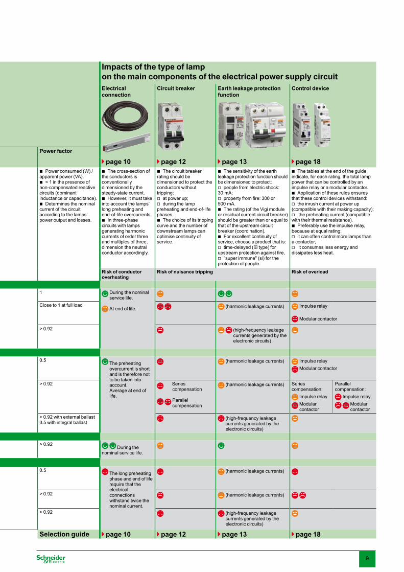
Impacts of the type of lamp on the main components of the electrical power supply circuitElectrical connection
Circuit breaker Earth leakage protection function
Control device
1 Inrush current at power up 2 Preheating current
3 Steady-state current Power factor
End of life page 10 page 12 page 13 page 18
100 ms20In
I
100 ms20In
I
20 msIn
I All discharge lamps (fluorescentandhigh intensity) require a phase of gas ionisation before ignition which results in over-consumption
100 ms20
In
I
100 ms20
In
I Over-consumption beyond the nominal service life (time after which 50% of the lamps of a given type are at end of life)
Power consumed (W) / apparent power (VA).
< 1 in the presence of non-compensated reactive circuits (dominant inductance or capacitance).
Determines the nominal current of the circuit according to the lamps’ power output and losses.
b
b
b
The cross-section of the conductors is conventionally dimensioned by the steady-state current.
However, it must take into account the lamps’ long preheating and end-of-life overcurrents.
In three-phase circuits with lamps generating harmonic currents of order three and multiples of three, dimension the neutral conductor accordingly.
b
b
b
The circuit breaker rating should be dimensioned to protect the conductors without tripping:
at power up;during the lamp
preheating and end-of-life phases.
The choice of its tripping curve and the number of downstream lamps can optimise continuity of service.
b
vv
b
The sensitivity of the earth leakage protection function should be dimensioned to protect:
people from electric shock: �0 mA;
propertyfromfire:300or500 mA.
The rating (of the Vigi module or residual current circuit breaker) should be greater than or equal to that of the upstream circuit breaker (coordination).
For excellent continuity of service, choose a product that is:
time-delayed (s type) for upstreamprotectionagainstfire,
"super immune" (si) for the protection of people.
b
v
v
b
b
v
v
The tables at the end of the guide indicate, for each rating, the total lamp power that can be controlled by an impulse relay or a modular contactor.
Application of these rules ensures that these control devices withstand:
the inrush current at power up (compatible with their making capacity);
the preheating current (compatible with their thermal resistance).
Preferably use the impulse relay, because at equal rating:
it can often control more lamps than a contactor,
it consumes less energy and dissipates less heat.
b
b
v
v
b
v
v
Non-deformation on passive impedances
Distortion created by electronic converter rectification/filteringVery low resistance
ofthefilamentwhencold
Initial saturation of ferromagnetic circuits
Initial charging of circuit capacitors
Risk of conductor overheating
Risk of nuisance tripping Risk of overload
Incandescent lampsBasic and LV halogen
b 10 to 15 In for 5 to 10 ms
b Up to 2 times the nominal current
1 During the nominal service life.
At end of life.
ELV halogen lamps + ferromagnetic transformer
20 to 40 In for 5 to 10 msb b Close to 1 at full load (harmonic leakage currents) Impulse relay
Modular contactor
ELV halogen lamps + electronic transformer
b �0 to 100 In for 0.5 ms
b > 0.92 (high-frequency leakage currents generated by the electronic circuits)
Fluorescent lamps withnon-compensated ferromagnetic ballast
b 10 to 15 In for 5 to 10 ms
Duration: from a few tenths of a second to a few seconds
Amplitude: from 1.5 to 2 times the nominal current In
b
b
b Up to 2 times the nominal current
0.5 The preheating overcurrent is short and is therefore not to be taken into account. Average at end of life.
(harmonic leakage currents) Impulse relay Modular contactor
compensated ferromagnetic ballast
b 20 to 60 In for 0.5 to 1 ms
b > 0.92 Series compensation
Parallel compensation
(harmonic leakage currents) Series compensation:
Impulse relay Modular contactor
Parallel compensation:
Impulse relay Modular
contactorelectronic ballast b �0 to 100 In
for 0.5 msb > 0.92 with external ballast
0.5 with integral ballast (high-frequency leakage currents generated by the electronic circuits)
LEDLight-emitting diodes
b See manu-facturer's data
> 0.92 During the nominal service life.
High-intensity discharge lamps withnon-compensated ferromagnetic ballast
b 10 to 15 In for 5 to 10 ms
Duration: from 1 to 10 mn
Amplitude: from 1.1 to 1.6 times the nominal current In
b
b
b Up to 2 times the nominal current
0.5 The long preheating phase and end of life require that the electrical connections withstand twice the nominal current.
(harmonic leakage currents)
compensated ferromagnetic ballast
b 20 to 60 In for 0.5 to 1 ms
b > 0.92 (harmonic leakage currents)
electronic ballast b �0 to 100 In for 0.5 ms
b > 0.92 (high-frequency leakage currents generated by the electronic circuits)
Selection guide page 10 page 12 page 13 page 18
9
Lamp selected
Page 6
Induced electrical constraints
Current profile of a lamp in its various phases over time
1 2
Power up0.5 to 100 ms
Preheating1 s to 10 min.
Steady-state (In)
t
Start of life
End of life
t
Impacts of the type of lamp on the main components of the electrical power supply circuitElectrical connection
Circuit breaker Earth leakage protection function
Control device
1 Inrush current at power up 2 Preheating current
3 Steady-state current Power factor
End of life page 10 page 12 page 13 page 18
100 ms20In
I
100 ms20In
I
20 msIn
I All discharge lamps (fluorescentandhigh intensity) require a phase of gas ionisation before ignition which results in over-consumption
100 ms20
In
I
100 ms20
In
I Over-consumption beyond the nominal service life (time after which 50% of the lamps of a given type are at end of life)
Power consumed (W) / apparent power (VA).
< 1 in the presence of non-compensated reactive circuits (dominant inductance or capacitance).
Determines the nominal current of the circuit according to the lamps’ power output and losses.
b
b
b
The cross-section of the conductors is conventionally dimensioned by the steady-state current.
However, it must take into account the lamps’ long preheating and end-of-life overcurrents.
In three-phase circuits with lamps generating harmonic currents of order three and multiples of three, dimension the neutral conductor accordingly.
b
b
b
The circuit breaker rating should be dimensioned to protect the conductors without tripping:
at power up;during the lamp
preheating and end-of-life phases.
The choice of its tripping curve and the number of downstream lamps can optimise continuity of service.
b
vv
b
The sensitivity of the earth leakage protection function should be dimensioned to protect:
people from electric shock: �0 mA;
propertyfromfire:300or500 mA.
The rating (of the Vigi module or residual current circuit breaker) should be greater than or equal to that of the upstream circuit breaker (coordination).
For excellent continuity of service, choose a product that is:
time-delayed (s type) for upstreamprotectionagainstfire,
"super immune" (si) for the protection of people.
b
v
v
b
b
v
v
The tables at the end of the guide indicate, for each rating, the total lamp power that can be controlled by an impulse relay or a modular contactor.
Application of these rules ensures that these control devices withstand:
the inrush current at power up (compatible with their making capacity);
the preheating current (compatible with their thermal resistance).
Preferably use the impulse relay, because at equal rating:
it can often control more lamps than a contactor,
it consumes less energy and dissipates less heat.
b
b
v
v
b
v
v
Non-deformation on passive impedances
Distortion created by electronic converter rectification/filteringVery low resistance
ofthefilamentwhencold
Initial saturation of ferromagnetic circuits
Initial charging of circuit capacitors
Risk of conductor overheating
Risk of nuisance tripping Risk of overload
Incandescent lampsBasic and LV halogen
b 10 to 15 In for 5 to 10 ms
b Up to 2 times the nominal current
1 During the nominal service life.
At end of life.
ELV halogen lamps + ferromagnetic transformer
20 to 40 In for 5 to 10 msb b Close to 1 at full load (harmonic leakage currents) Impulse relay
Modular contactor
ELV halogen lamps + electronic transformer
b �0 to 100 In for 0.5 ms
b > 0.92 (high-frequency leakage currents generated by the electronic circuits)
Fluorescent lamps withnon-compensated ferromagnetic ballast
b 10 to 15 In for 5 to 10 ms
Duration: from a few tenths of a second to a few seconds
Amplitude: from 1.5 to 2 times the nominal current In
b
b
b Up to 2 times the nominal current
0.5 The preheating overcurrent is short and is therefore not to be taken into account. Average at end of life.
(harmonic leakage currents) Impulse relay Modular contactor
compensated ferromagnetic ballast
b 20 to 60 In for 0.5 to 1 ms
b > 0.92 Series compensation
Parallel compensation
(harmonic leakage currents) Series compensation:
Impulse relay Modular contactor
Parallel compensation:
Impulse relay Modular
contactorelectronic ballast b �0 to 100 In
for 0.5 msb > 0.92 with external ballast
0.5 with integral ballast (high-frequency leakage currents generated by the electronic circuits)
LEDLight-emitting diodes
b See manu-facturer's data
> 0.92 During the nominal service life.
High-intensity discharge lamps withnon-compensated ferromagnetic ballast
b 10 to 15 In for 5 to 10 ms
Duration: from 1 to 10 mn
Amplitude: from 1.1 to 1.6 times the nominal current In
b
b
b Up to 2 times the nominal current
0.5 The long preheating phase and end of life require that the electrical connections withstand twice the nominal current.
(harmonic leakage currents)
compensated ferromagnetic ballast
b 20 to 60 In for 0.5 to 1 ms
b > 0.92 (harmonic leakage currents)
electronic ballast b �0 to 100 In for 0.5 ms
b > 0.92 (high-frequency leakage currents generated by the electronic circuits)
Selection guide page 10 page 12 page 13 page 18

10
Usual valuesPower output per phase of a lighting circuit:common values: 0.� to 0.8 kWmaximum values:110 V: up to 1 kW220 to 240 V: up to 2.2 kWPower factor:
> 0.92 (compensated circuit or electronic ballast)Maximumadmissiblevoltagedrop(∆U)insteady
state: �% for circuits less than 100 m,�.5% permissible above 200 m.Cable cross-section:most commonly (< 20 m): 1.5 or 2.5 mm2, very long (> 50 m) high-power circuit, to limit
voltage drops: 4 to 6 mm², or even 10 mm² (> 100 m)
bvv--b
b
vvbvv
Conductor cross-sectionCables: Fast dimensioning page 14
Optimised calculation "My Ecodial" software
Electrical distributionCable and prefabricated busbar trunking selection principles
Power distributionThe electrical conductors have to transport energy from the electrical switchboard
to the lighting loads.They can be cables or prefabricated busbar trunking. Where large areas have to be lit, they comprise a main circuit and branch circuits
tothelightfittings.Their selection depends on various constraints:safety (insulation, little overheating, mechanical strength, etc.);efficiency(limitedvoltagedrop,etc.);installation environment (location, installation procedure, temperature, etc.);investment cost.
b
bb
bvvvv
Nominal current of circuitsThe total circuit power must be analysed and calculated: lamp power consumption;any lamp ballast or transformer losses.Depending on the type of load and any compensation, a power factor must be applied.
Apoorpowerfactor,forexample,candoublethecurrentflowingthroughthecircuits.For sizing electrical distribution, one should allow for the fact that the lamps
consume 1.5 to 2 times their nominal current:at end of life for all lamps;during the long preheating phase for high-intensity discharge lamps.
bvvb
b
vv
Copper is less resistive but more expensive than aluminium. The use of aluminium is reserved for high-current electrical distribution.
Conductive material
The cable resistance induces a voltage drop proportional to the cable length and the current. It can cause malfunctions when the lamps are switched on or reduce the luminosity in steady state. The length of the circuits and the distributed power require an appropriate cable cross-section.
Length of electrical distribution
Cable cross-section dimensioning factors
Derating factors to prevent overheating of electrical conductors
Loaded neutral correction factor
In the case of three-phase circuits supplying discharge lamps with electronic ballasts, harmonic currents of the third order and multiples of three are generated.Theyflowthroughthephaseconductors and combine in the neutral cable, generating a possible overload. The circuit must therefore be sized according to this harmonic rate.
Mutual interference in the case of adjacent circuits
Ambient temperature1% to 2% derating per °C above the nominal temperature
Installation procedureBuried or otherwise, on cable trays or embedded, etc.
Type of insulating material
In most buildings used for tertiary or commercial purposes, the lighting system is distributed via a single-phase circuit. To optimise the cabling, especially for high-power applications over large areas, three-phase distribution is sometimes used: 2�0 V between phase and neutral or between phases, or 400 V between phases for high-power lamps (2000 W)
Single-phase or three-phase distribution with or without meutralL1
N
U = 230V
PE
NUU
U = 230 V ou 400 V
UL3
L1
L2
L3
PE
L1
L2
U
UU
U = 230V
L3
N
L1
L2
L3
N
L1
PE
L2
U = 2�0 V U = 2�0 V or 400 VU = 2�0 V

11
Canalis prefabricated busbar trunkingThese systems meet the needs of all applications in commercial, tertiary and industrial buildings.
Advantages in every stage in the life of a building
Canalis KDP Canalis KBA Canalis KBB
Installation Type flexible rigid very rigidInstallation procedure
installed in a suspended ceiling or falsefloor
attached to the structure of the building (installation spacing up to 0.7 m)
b
b
suspended (installation spacing up to � m)b suspended
(installation spacing up to 5 m)b
Lightfittingattachment to the trunking
no yes yes
Prewiredlightfittingoffering - Canalis KBL Canalis KBLPower circuits
Quantity 1 1 1 ou 2Type single-phase
three-phasebb
single-phasethree-phase
bb
single-phasethree-phasesingle-phase + single-phasesingle-phase + three-phasethree-phase + three-phase
bbbbb
single-phase: 2 conductors + PE three-phase: 4 conductors + PE
Remote control circuit - optional optionalRating 20 A 25 or 40 A 25 or 40 ATap-off spacing 1.2 - 1.�5 - 1.5 - 2.4 - 2.7 - � m no tap-off or 0.5 - 1 - 1.5 m no tap-off or 0.5 - 1 - 1.5 m
DesignSimplifiedelectricalcircuitdiagramDirect choice of model, depending on the type and
number of lampsDirect correspondence between the circuit breaker
rating and that of the trunking (example at �5°C: KDP 20 A -> 20 A circuit breaker)
Guaranteed performance irrespective of the installation (in accordance with the IEC 604�9-2 standard)
Suitable for all environments: IP 55 as standard, in conformity with sprinkler tests
Protects the environment: RoHSNohalogen:releasesnotoxicfumesincaseoffire
bb
b
b
b
bb
ImplementationEase of installation: no
risk of wiring errorCan be installed by
unskilled personnel (connection by connectors, polarising, etc.)
Reduction in worksite time, control of completion times
Prefabricated, pretested: operates immediately on commissioning
b
b
b
b
Operation and maintenance
Quality of contacts of clamp type active conductors
Long service life, maintenance-free (up to 50 years)
Continuity of service and safety: servicing can be performed on live lines Significantreductionof
radiated electromagnetic fields
b
b
b
b
Changes in the building
Modular, hence dismountable and reusableRefittingofpremises
andtheirlightfittingsfacilitated by the branch connections available at regular intervals
Legibility of the installation for servicing operations and upgrades
b
b
b
Type of electrical distribution Cables Canalis
Criteria to be taken into account for sizingInstallation procedure (generating possible overheating) b
Mutual interference in the case of adjacent circuits b
Ambient temperature b b
Type of electric insulating material b
Loaded neutral correction factor (three-phase circuit with high harmonic distortion factor)
b b
Conductive material b
Length of electrical distribution b b
Nominal current of circuits b b easier selection, by lamp type
Canalis :Fast dimensioning page 16
Optimised calculation "My Ecodial" software
12
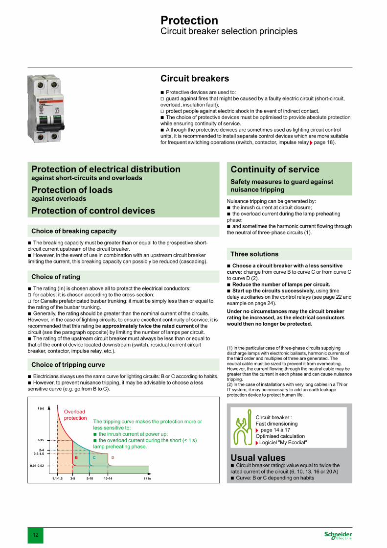
ProtectionCircuit breaker selection principles
Circuit breaker :Fast dimensioning page 14 à 17
Optimised calculation Logiciel "My Ecodial"
Usual valuesCircuit breaker rating: value equal to twice the
rated current of the circuit (6, 10, 1�, 16 or 20 A)Curve: B or C depending on habits
b
b
Nuisance tripping can be generated by:the inrush current at circuit closure; the overload current during the lamp preheating
phase;andsometimestheharmoniccurrentflowingthrough
the neutral of three-phase circuits (1).
bb
b
Continuity of serviceSafety measures to guard against nuisance tripping
7-15
t (s)
2-40.5-1.5
0.01-0.02
1.1-1.5 3-5
B C D
5-10 10-14 I / In
The tripping curve makes the protection more or less sensitive to:
the inrush current at power up;the overload current during the short (< 1 s)
lamp preheating phase.
bb
Overload protection
Three solutionsChoose a circuit breaker with a less sensitive
curve: change from curve B to curve C or from curve C to curve D (2).
Reduce the number of lamps per circuit.Start up the circuits successively, using time
delay auxiliaries on the control relays (see page 22 and example on page 24).Under no circumstances may the circuit breaker rating be increased, as the electrical conductors would then no longer be protected.
(1) In the particular case of three-phase circuits supplying discharge lamps with electronic ballasts, harmonic currents of the third order and multiples of three are generated. The neutral cable must be sized to prevent it from overheating. However,thecurrentflowingthroughtheneutralcablemaybegreater than the current in each phase and can cause nuisance tripping.(2) In the case of installations with very long cables in a TN or IT system, it may be necessary to add an earth leakage protection device to protect human life.
b
bb
Protection of electrical distribution against short-circuits and overloads
Protection of loads against overloads
Protection of control devices
Circuit breakersProtective devices are used to:guardagainstfiresthatmightbecausedbyafaultyelectriccircuit(short-circuit,
overload, insulation fault);protect people against electric shock in the event of indirect contact.The choice of protective devices must be optimised to provide absolute protection
while ensuring continuity of service.Although the protective devices are sometimes used as lighting circuit control
units, it is recommended to install separate control devices which are more suitable for frequent switching operations (switch, contactor, impulse relay page 18).
bv
vb
b
Choice of breaking capacity The breaking capacity must be greater than or equal to the prospective short-
circuit current upstream of the circuit breaker.However, in the event of use in combination with an upstream circuit breaker
limiting the current, this breaking capacity can possibly be reduced (cascading).
b
b
Choice of tripping curveElectricians always use the same curve for lighting circuits: B or C according to habits.However, to prevent nuisance tripping, it may be advisable to choose a less
sensitive curve (e.g. go from B to C).
bb
Choice of ratingThe rating (In) is chosen above all to protect the electrical conductors:for cables: it is chosen according to the cross-section;for Canalis prefabricated busbar trunking: it must be simply less than or equal to
the rating of the busbar trunking.Generally, the rating should be greater than the nominal current of the circuits.
However, in the case of lighting circuits, to ensure excellent continuity of service, it is recommended that this rating be approximately twice the rated current of the circuit (see the paragraph opposite) by limiting the number of lamps per circuit.
The rating of the upstream circuit breaker must always be less than or equal to that of the control device located downstream (switch, residual current circuit breaker, contactor, impulse relay, etc.).
bvv
b
b

1�
Earth leakage protection devicesEarth leakage protection devices are used to:guardagainstfiresthatmightbecausedbyanelectriccircuitwithaninsulation
fault;protect people against electric shock (direct or indirect contact).The choice of protective devices must be optimised to provide absolute protection
while ensuring continuity of service.The implementation of earth leakage protection on lighting circuits varies
according to standards, neutral system and installation habits.
bv
vb
b
ProtectionEarth leakage protection device selection principles
Protecting the installation against fires generated by a cable insulation fault
Protecting people against electric shock
Choice of sensitivityForprotectionagainstfireonly:300mA.For protection against electric shock: �0 mA.
bb
Choice of ratingThe rating must be greater than or equal to the total consumption of the circuit.
This consumption can be as much as twice the rated current of the lamps:in the case of discharge lamps, due to the long preheating time (several minutes);higher consumption by lamps that have exceeded their nominal service life.The rating of the earth leakage protection function (Vigi module or residual current
circuit breaker) should always be greater than or equal to the rating of the upstream circuit breaker.
b
vvb
si type technology
Red curve : international standard IEC 479 determines the limit current for earth leakage protection tripping according to the frequency. This limit corresponds to the current that the human body is capable of withstanding without any danger.
Black curve : standard earth leakage protection devices (blue curve) are more sensitive to high-frequency currents than to 50/60 Hz.
Green curve : the "si" "super immune" protections are less sensitive to high-frequency disturbances, whilst at the same time ensuring personal safety.
b
b
b
DiscriminationFor a two-level earth leakage protection system, the
following are recommended:upstream time-delayed earth leakage protection
device with sensitivity greater than or equal to three times the downstream protection device (for example 100 or �00 mA s type protection);
one or more instantaneous �0 mA earth leakage protection devices downstream.
b
v
v
Choice of time delay
Continuity of serviceSafety measures to guard against nuisance tripping
Si type "super immune" protectionCompactfluorescentlampsandhigh-intensity
discharge lamps with electronic ballast generate high-frequencycurrents(severalkHz)thatflowbetweenconductorsandearthintheballastinputfiltersandthrough stray capacitance in the installation.
These currents (up to several mA per ballast) can trip standard earth leakage protection devices.
To avoid such problems and maintain excellent continuity of service, Si type earth leakage protection is recommended.
b
b
b
"Super immune" protection
Tripping curve of a 30 mA earth leakage protection function
10 mA
1 mA10 Hz 100 Hz 1000 Hz 10000 Hz
100 mA
1000 mA
IEC standard 479
standard product
super immune protection (si)

14
Fast dimensioning of electrical distribution and protection Cable cross-section, circuit breaker rating
230 V AC single-phase copper cable
infrequently used recommended acceptable not recommended (high inrush currents) risk of overheating / overloading the cable
example described at the bottom of the page
(1) If the voltage or power factor is different, the lighting power and the cable length must be recalculated (the value of the rated current does not change):
for a voltage of 110-115 V: divide the values by 2 for a different power factor, see the table below:
Cos multipliercoefficienttobeappliedforpower length
0.85 0.895 1.1180.5 0.526 1.9
(2) Maximum values not to be exceeded to guarantee cable protection.
bb
From the main characteristics of the installation (lighting power, distance from electrical switchboard), these tables can be used to determine:
the cross-section of the conductors on the power supply line for a voltage drop less than �% at the lamps, whatever the installation method and insulating material used for the conductors,
the circuit breaker rating for protection and continuity of service with a safety margin, whatever the type of lamps.
b
b
Example of an open-plan office Characteristics of the installation: 30lightfittingswith2x18W230Vsingle-phasefluorescentlamps,Power factor (Cos ): 0.95 Average distance from the switchboard: 60 m
Calculations: Lamp power: �0 x 2 x 18 = 1080 W Ballast losses, estimated at 10% of the lamp power: i.e. 108 W Lighting power (P):
1080 + 108 = 1188 W = 1.2 kW the next highest value in the table, i.e.1.3 kW is selected.
Corresponding rated current (I = P / U Cos ) : = 1188 W / (2�0 V x 0.95) = 5.4 A the next highest value in the table, i.e. 6 A is selected.
Average lamp distance: 60 m the next highest value in the table, i.e. 82 m is selected.Cable and protection values selected:
The cable cross-section recommended so as not to exceed a �% voltage drop at the end of the line is therefore: 2,5 mm²
Minimum recommended circuit breaker rating: 2 x 6 A = 12 A, equivalent to the next highest standard value of 13 A or 16 A This rating is in fact less than or equal to the maximum authorised rating (16 or 20 A) to ensure that the cable is protected.
bbb
bbb
b
b
b
b
Characteristics of the installation at 40°C, 2�0 V AC, Cos = 0.95 (1)Lighting power (kW)including any ballast losses
Rated current (A)
Maximum cable length (m) for a �% voltage drop (the value shown is the average distance between the electrical switchboard and the lamps)
0.2 1 294 489 78�0.4 2 147 245 �91 5870.7 � 98 16� 261 �91 6521.� 6 49 82 1�0 196 �26 5222.2 10 29 49 78 117 196 �1� 489�.5 16 18 �1 49 7� 122 196 �064.4 20 24 �9 59 98 157 2455.5 25 �1 47 78 125 1967.0 �2 24 �7 61 98 15�8.7 40 29 49 78 12210.9 50 �9 6� 981�.8 6� 50 78CableCross-section of each conductor (mm2)
1,5 2,5 4 6 10 16 25
Circuit breaker Rating (A)
recommended twice the rated current of the lighting circuit 2 x 6 A = 13 or 16 A
maximum (2)cable with PVC insulation
1� 16 25 �2 40 50 6�
other insulating materialmoreefficientat high temperature
16 20 �2 40 50 6� 80

15
Three-phase copper cable
230 V AC between phase and neutral or 400 V AC between phases
infrequently used recommended acceptable not recommended (high inrush currents) risk of overheating / overloading the cable
example described at the bottom of the page (with table value correction allowing for a power factor of 0.85)
(1) If the voltage or power factor is different, the lighting power and the cable length must be recalculated (the value of the rated current does not change):
for a different voltage, multiply the lighting power and the cable length by:
0.577 for a voltage of 2�0 V between phases 0.5 for a voltage of 110-115 V between phase and neutral for a different power factor, see the table below:
Cos multipliercoefficienttobeappliedforpower cable length
0.85 0.895 1.1180.5 0.526 1.9
(2) Maximum values not to be exceeded to guarantee cable protection.
b
vvb
Example of a warehouse Characteristics of the installation:
�9 x 70 W 2�0 V sodium vapour lamps with compensation, connected to a three-phase circuit between phase and neutral
Power factor (Cos ) : 0.85Average distance from the switchboard: 120 m
Calculations : Lamp power per phase:
(�9 x 70) / � = 910 WBallast losses per phase, estimated at 10% of the lamp power: i.e. 91 W Lighting power per phase (P) :
910 + 91 = 1001 W = 1 kWCorresponding current (I = P / U Cos ) :
= 1001 W / (2�0 V x 0.85) = 5.1 A the next highest value in the table, i.e. 6 A is selected.
Correction of the values in the table for the maximum cable length to take the power factor into consideration:
98 x 1.118 = 110 m16� x 1.118 = 182 m
the corrected value immediately above 120 m in the table, i.e. 182 m is selected.Cable and protection values selected:
The cable cross-section per phase recommended so as not to exceed a �% voltage drop at the end of the line is therefore: 2,5 mm²
Minimum recommended circuit breaker rating: twice 6 A, i.e. 13 A or 16 A as the standard value. This rating is in fact less than or equal to the maximum authorised rating (16 or 20 A) to ensure that the cable is protected.
b
bb
b
bb
b
b
vv
b
b
Characteristics of the installation three-phase balanced circuit, at 40°C, Cos = 0.95 2�0 V AC between phase and neutral or 400 V AC between phases (1)Lighting power per phase (kW)including any ballast losses
Rated current per phase (A)
Maximum cable length (m) for a �% voltage drop (the value shown is the average distance between the electrical switchboard and the lamps)
0.2 1 587 978 15650.4 2 294 489 78� 11740.7 � 196 �26 522 78� 1�041.� x 0.895 = 1.2 6 98 110 16� 182 261 �91 652 10442.2 10 59 98 157 2�5 �91 626 978�.5 16 �7 61 98 147 245 �91 6114.4 20 49 78 117 196 �1� 4895.5 25 6� 94 157 250 �917.0 �2 49 7� 122 196 �068.7 40 59 98 157 24510.9 50 78 125 1961�.8 6� 99 155CableNeutral conductor cross-section equal to the phase cable cross-section Cross-section of each conductor (mm2)
1.5 2.5 4 6 10 16 25
Circuit breakerRating (A)
recommended twice the rated current of the lighting circuit 2 x 6 A = 13 or 16 A
maximum (2)
cable with PVC insulation
1� 16 25 �2 40 50 6�
other insulating materialmoreefficientat high temperature
16 20 �2 40 50 6� 80

16
Fast dimensioning of electrical distribution and protection Type of Canalis, circuit breaker rating
Characteristics of a light line 30lightfittingswith2x58W230Vfluorescent
lamps, evenly spaced along 75 m and suspended from a rigid KBA type busbar trunking
Single-phase or three-phase power supply: under consideration
Power factor: 0.95 Operating temperature: < �5°C
Calculations: Power of the lamps: �0 x 2 x 58 = �480 W Ballast losses, estimated at 10% of the lamp power:
i.e. �48 W Lighting power: �480 + �48 = �828 W = �.8� kW, i.e. 1.28 kW per
phase for a three-phase supply Corresponding rated current (I = P / U Cos ): single-phase: �828 W / (2�0 V x 0.95) = 17.5 A three-phase (2�0 V between phase and neutral): 17.5 / � = 5.85 A per phase
b
b
bb
bb
bb
bvvv
Step 1: Select the busbar trunking rating according to the number and type of lamps Characteristics of the lamps Characteristics of the circuit
�5°C, voltage drop to be checked according to the length of the busbar trunking in the following table type of lamp the most commonly used with prefabricated busbar trunking systems
power-factor correction
lamp unit power (W)without control ballast losses
230 V single-phase circuit three-phase circuit 400 V between phases, or 2�0 V between phase and neutral
flexible(KDP) rigid (KBA or KBB) flexible(KDP) rigid (KBA or KBB)20 A 25 A 40 A 20 A 25 A 40 A
Maximum number of light fittings and maximum total power Fluorescent tubes yes �6 W 66 2400 W
to �000 W66 �750 W 66 6000 W 99 � x 1200 W
to � x �000 W
99 � x 1200 W to � x �750 W
99 � x 1200 W to � x �750 W
58 W 50 62 62 75 75 752 x �6 W 42 52 67 99 99 992 x 58 W 26 �2 52 78 96 96
no �6 W 44 1600W 55 2000 W 55 �250 W 105 � x 1600 W 105 � x 2000 W 105 � x �250 W58 W 28 �5 45 84 84 842 x �6 W 22 27 44 66 81 812 x 58 W 14 17 28 42 51 84
High-pressure mercury vapour lamps
yes 250 W 14 �500 W 17 4250 W 22 5500 W Usage infrequent
51 � x �750 W 66 � x �750 W400 W 8 10 1� �0 �9
no 250 W 9 2400 W 11 2800 W 14 �600 W �� � x 2000 W 42 � x �250 W400 W 6 7 9 21 27
High-pressure sodium vapour lamps or metal-iodide lamps
yes 150 W 22 ��00 W to �600 W
27 4100 W to 4400 W
�5 5250 W to 5600 W
81 � x 4050 W to � x 4400 W
105 � x 5250 W to � x 5600 W
250 W 14 17 22 51 66400 W 9 11 14 �� 42
no 150 W 11 1650W 1� 2000 W 17 2550 W �9 � x2000 W 51 � x 2550 W250 W 6 8 10 24 �0400 W 4 5 6 15 18
These tables are used to determine from the main characteristics of the installation (typeofflexibleorrigidbusbartrunking,typeoflamp,lightingpower,distancefromthe electrical switchboard):
the busbar trunking rating (20, 25 or 40 A) for a voltage drop less than �% at the lamps,
the circuit breaker rating for protection and continuity of service with a safety margin, whatever the type of lamps.
b
b
Step 1: select the busbar trunking rating according to the number and type of lamps (see table above)Find the example in the table: Line:fluorescenttubewithpowerfactorcorrection,type2x58WColumn:ifsingle-phasecircuit:KBA25Aseemssufficientas30lightfittings<32ifthree-phasecircuit:KBA25Aseemssufficientas30lightfittings<96
Step 2: confirm the busbar trunking rating according to the length of the circuit (tables on next page)Find the example in the table:
single-phase: 16 A < 17.5 A < 20 A, the max. corresponding lengths for KBA 25 A (70 and 56 m) are less than the 75 m
of the installation. This requires changing to KBA 40 A to ensure a voltage drop < �%. This busbar
trunking overdimensioning leads us to consider a three-phase solution.three-phase: 5.85 A is almost 6 A, the max. corresponding length for KBA 25 A (�75 m) is far longer than 75 m therefore a three-phase KBA 25 A solution guarantees a voltage drop that is far
less than �% at the end of the busbar trunking. Select the circuit breaker rating:Minimum value: twice 6 A = 12 A, i.e. 1� or 16 A as the nearest standard value. Note: a higher rating (up to 25 A) is possible and guarantees that the busbar trunking is protected. However, it is important to check that this rating is also compatible with the busbar trunking supply cable protection.
bbvv
bvv
v
bvvv
Example of a factory
example described on page 16

17
Step 2: confirm the busbar trunking rating according to the length of the circuit and select the circuit breaker rating
Three-phase 230 V AC Canalis busbar trunking between phase and neutral or 400 V AC between phases Characteristics of the installation at �5°C, Cos = 0.95 2�0 V AC between phase and neutral or 400 V AC between phases (2)Lighting power per phase (W)including any ballast losses
Rated current per phase (A)
Maximum length of the busbar trunking (m)for a voltage drop < �% at the end of the busbar trunking Lamps evenly spaced along the busbar trunking (most common case)
0.2 10.4 20.7 � 661 7511.� 6 ��0 �75 7692.2 10 198 225 461�.5 16 124 141 2884.4 20 49 11� 2�15.5 25 90 1847.0 �2 1448.7 40 Overloaded 11510.9 50 busbar trunking 1�.8 6�Busbar trunking systemType of busbar trunking flexible(KDB) rigid (KBA or KBB)Rating (A) 20 25 40Circuit breaker Rating (A)
recommended twice the rated current of the lighting circuit 2 x 6 A = 13 or 16 A
maxi 20 25 40
Single-phase Canalis 230 V AC busbar trunking Characteristics of the installationat �5°C, Cos = 0.95 (1)Lighting power (W)including any ballast losses
Rated current (A)
Maximum length of the busbar trunking (m)for a voltage drop < �% at the end of the busbar trunking Lamps evenly spaced along the busbar trunking (most common case)
0.2 10.4 20.7 � ��0 �751.� 6 165 188 �842.2 10 99 11� 2�1�.5 16 62 70 1444.4 20 49 56 1155.5 25 45 927.0 �2 728.7 40 5810.9 50 Overloaded busbar trunking 1�.8 6�Busbar trunking systemType of busbar trunking flexible
(KDB)rigid (KBA or KBB)
Rating (A) 20 25 40Circuit breaker Rating (A)
recommended twice the rated current of the lighting circuit
maxi 20 25 40
(1) If the voltage or power factor is different, some values in the table must be recalculated (the value of the rated current does not change):
for a voltage of 110-115 V: divide the values by 2 for a different power factor, see the table below:
Cos multipliercoefficienttobeappliedforpower length of the busbar
trunking 0.85 0.895 1.1180.5 0.526 1.9
(2) If the voltage or power factor is different, the lighting power and the length of the busbar trunking must be recalculated (the value of the rated current does not change):
for a different voltage, multiply the lighting power and the busbar trunking length by:0.577 for a voltage of 2�0 V between phases 0.5 for a voltage of 110-115 V between phase and neutral for a different power factor, see the table below:
Cos multipliercoefficienttobeappliedforpower length of the busbar
trunking 0.85 0.895 1.1180.5 0.526 1.9
bb
bvvb
infrequently used recommended acceptable not recommended (high inrush currents) risk of overheating / overloading the cable
example described on page 16

18
Control devicesImpulse relay and modular contactor selection principles
Circuit without relay (switch )
Impulse relay Modular contactor
Choice of control relay
Type of architecture Directly controls the power circuit
The control and power circuits are separate.They can also relay the management devices ( page 2�), which often have a limited switching capacity.
Installation As ambience lighting (wall-mounted)
In an enclosure
Control Number of points
1 to � Multiple Single (as standard) or multiple (with auxiliary)
Type Direct Impulse-type by pushbutton
Latched-type by switch (as standard) or impulse-type by pushbutton (with auxiliary)
Consumption None None except when controlled
When it is in operation (1 to 2 W)
Rating (most common values in bold)
6, 10 or 16 A 16 or �2 A 16, 25, 40, 6� A
Installation options For 2 control points, use 2 two-way switches
For � control points, use a four-way switch and 2 two-way switches
b
b
Many possible functions by using auxiliaries:time delayilluminated pushbutton controlstep-by-step controlsignalling latched-type controlcentralised multi-level control
bbbbbb
Controlled power Less than 1 kW Several kWType of circuit controlled Single-phase Single-phase (1 or 2 P) or
three-phase (� or 4 P monobloc or in conjunction with ETL extension)
Single-phase (1 or 2 P) or three-phase (� or 4 P)
Number of lamps controlled To be calculated pages 20 and 21
Control devicesTheirroleistocontrollightfittingswitchingonandoffbyswitchingthephase
conductor(s).They are located downstream of the protective devices, at the head of each
lighting circuit.Their technology allows a very large number of switching operations
(approximately 100,000) to be performed without adversely affecting their performance, in normal operating conditions.
The installation of a control relay (impulse relay, contactor) allows:remote control of a high-power lighting circuit;sophisticated functions (central control, timer, programming, etc.).
b
b
b
bvv
TL CT
High-performance CT+ contactor and TL+ impulse relayDesigned for demanding applications
Silent and compact Very long service life No electromagnetic interferenceEspecially appropriate for controlling
ferro-magnetic ballast lamps consuming up to 20 A (CT+) or 16 A (TL+) in steady state.
bbbb
ETL CT
CT+
19
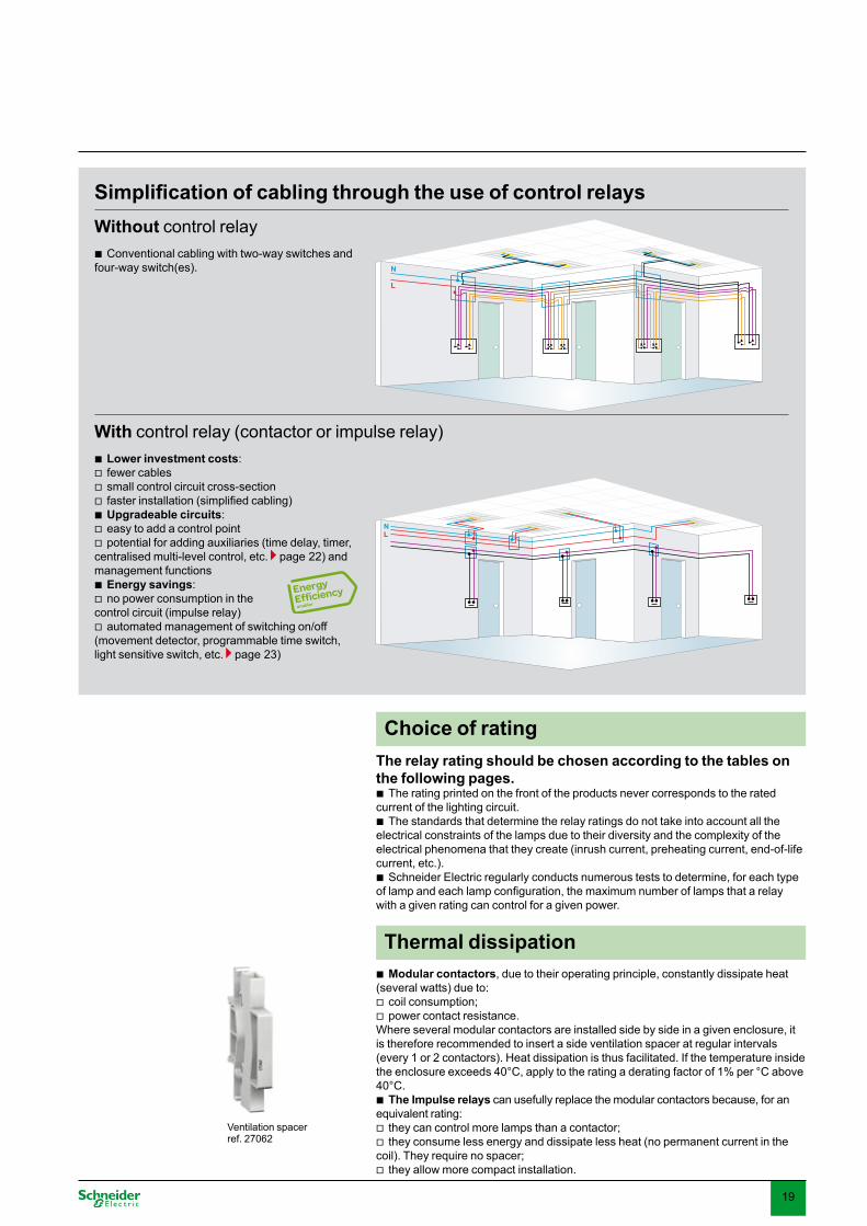
Conventional cabling with two-way switches and four-way switch(es).b
Lower investment costs:fewer cablessmall control circuit cross-sectionfasterinstallation(simplifiedcabling)Upgradeable circuits:easy to add a control pointpotential for adding auxiliaries (time delay, timer,
centralised multi-level control, etc. page 22) and management functions
Energy savings:no power consumption in the
control circuit (impulse relay)automated management of switching on/off
(movement detector, programmable time switch, light sensitive switch, etc. page 2�)
bvvvbvv
bv
v
N
L
Simplification of cabling through the use of control relaysWithout control relay
With control relay (contactor or impulse relay)
Ventilation spacer ref. 27062
Choice of ratingThe relay rating should be chosen according to the tables on the following pages.
The rating printed on the front of the products never corresponds to the rated current of the lighting circuit.
The standards that determine the relay ratings do not take into account all the electrical constraints of the lamps due to their diversity and the complexity of the electrical phenomena that they create (inrush current, preheating current, end-of-life current, etc.).
Schneider Electric regularly conducts numerous tests to determine, for each type oflampandeachlampconfiguration,themaximumnumberoflampsthatarelaywith a given rating can control for a given power.
b
b
b
Modular contactors, due to their operating principle, constantly dissipate heat (several watts) due to:
coil consumption;power contact resistance.
Where several modular contactors are installed side by side in a given enclosure, it is therefore recommended to insert a side ventilation spacer at regular intervals (every 1 or 2 contactors). Heat dissipation is thus facilitated. If the temperature inside the enclosure exceeds 40°C, apply to the rating a derating factor of 1% per °C above 40°C.
The Impulse relays can usefully replace the modular contactors because, for an equivalent rating:
they can control more lamps than a contactor;they consume less energy and dissipate less heat (no permanent current in the
coil). They require no spacer;they allow more compact installation.
b
vv
b
vv
v
Thermal dissipation
NL

20
Selection of control devicesChoice of rating according to lamp type
Type of lamp
Unit powerand capacitance of power factor correction capacitor
Maximumnumberoflightfittingsforasingle-phasecircuitand maximum power output per circuitTL impulse relay CT contactor16 A �2 A 16 A 25 A 40 A 6� A
Basic incandescent lamps LV halogen lamps Replacement mercury vapour lamps (without ballast)
40 W 40 1500 W to 1600 W
106 4000 W to 4200 W
�8 1550 W to 2000 W
57 2�00 W to2850 W
115 4600 W to 5250 W
172 6900 W to 7500 W
60 W 25 66 �0 45 85 12575 W 20 5� 25 �8 70 100100 W 16 42 19 28 50 7�150 W 10 28 12 18 �5 50200 W 8 21 10 14 26 �7�00 W 5 1500 W 1� 4000 W 7 2100 W 10 �000 W 18 5500 W
to 6000 W
25 7500 W to 8000 W
500 W � 8 4 6 10 151000 W 1 4 2 � 6 81500 W 1 2 1 2 4 5
ELV 12 or 24 V halogen lampsWith ferromagnetic transformer
20 W 70 1�50 W to 1450 W
180 �600 W to �750 W
15 �00 W to 600 W
2� 450 W to 900 W
42 850 W to 1950 W
6� 1250 W to 2850 W
50 W 28 74 10 15 27 4275 W 19 50 8 12 2� �5100 W 14 �7 6 8 18 27
With electronic transformer 20 W 60 1200 W to 1400 W
160 �200 W to ��50 W
62 1250 W to 1600 W
90 1850 W to 2250 W
182 �650 W to 4200 W
275 5500 W to 6000 W
50 W 25 65 25 �9 76 11475 W 18 44 20 28 5� 78100 W 14 �� 16 22 42 60
Fluorescent tubes with starter and ferromagnetic ballast1 tube without compensation (1)
15 W 8� 1250 W to 1�00 W
21� �200 W to ��50 W
22 ��0 W to 850 W
�0 450 W to 1200 W
70 1050 W to 2400 W
100 1500 W to �850 W18 W 70 186 22 �0 70 100
20 W 62 160 22 �0 70 10036 W �5 9� 20 28 60 9040 W �1 81 20 28 60 9058 W 21 55 1� 17 �5 5665 W 20 50 1� 17 �5 5680 W 16 41 10 15 �0 48115 W 11 29 7 10 20 �2
1 tube with parallel compensation (2)
15 W 5 µF 60 900 W 160 2400 W 15 200 W to 800 W
20 �00 W to 1200 W
40 600 W to 2400 W
60 900 W to �500 W
18 W 5 µF 50 1�� 15 20 40 6020 W 5 µF 45 120 15 20 40 6036 W 5 µF 25 66 15 20 40 6040 W 5 µF 22 60 15 20 40 6058 W 7 µF 16 42 10 15 �0 4�65 W 7 µF 1� �7 10 15 �0 4�80 W 7 µF 11 �0 10 15 �0 4�115 W 16 µF 7 20 5 7 14 20
2 or 4 tubes with series compensation
2 x 18 W 56 2000 W 148 5�00 W �0 1100 W to 1500 W
46 1650 W to 2400 W
80 2900 W to �800 W
12� 4450 W to 5900 W4 x 18 W 28 74 16 24 44 68
2 x 36 W 28 74 16 24 44 682 x 58 W 17 45 10 16 27 422 x 65 W 15 40 10 16 27 422 x 80 W 12 �� 9 1� 22 �42 x 115 W 8 2� 6 10 16 25
Fluorescent tubes with electronic ballast1 or 2 tubes 18 W 80 1450 W
to 1550 W
212 �800 W to 4000 W
74 1�00 W to 1400 W
111 2000 W to 2200 W
222 4000 W to 4400 W
��� 6000 W to 6600 W
36 W 40 106 �8 58 117 17658 W 26 69 25 �7 74 1112 x 18 W 40 106 �6 55 111 1662 x 36 W 20 5� 20 �0 60 902 x 58 W 1� �4 12 19 �8 57
Relay ratingThetablebelowshowsthemaximumnumberoflightfittingsforeachrelay,
accordingtothetype,powerandconfigurationofagivenlamp.Asanindication,thetotal acceptable power is also mentioned.
These values are given for a 2�0 V circuit with 2 active conductors (single-phase phase/neutral or two-phase phase/phase). For 110 V circuits, divide the values in the table by 2.
To obtain the equivalent values for the entire 2�0 V three-phase circuit, multiply the number of lamps and the maximum power output:
by 3 (1.7�) for circuits with 2�0 V between phases without neutral;by � for circuits with 2�0 V between phase and neutral or 400 V between phases.
Note: The power ratings of the lamps most commonly used are shown in bold. For powers not mentioned, use a proportional rule with the nearest values.
b
b
b
vv
General commentModular contactors and impulse relays do not use the same technologies. Their rating is determined according to different standards and does not correspond to the rated current of the circuit (except for TL+ and CT+).For example, for a given rating, an impulserelayismoreefficientthanamodular contactor for the control of light fittingswithastronginrushcurrent,orwith a low power factor (non-compensated inductive circuit).
CT+, TL+ !
CT+, TL+ !
CT+, TL+ !

21
Type of lamp
Unit powerand capacitance of power factor correction capacitor
Maximumnumberoflightfittingsforasingle-phasecircuitand maximum power output per circuitTL impulse relay CT contactor16 A �2 A 16 A 25 A 40 A 6� A
Compact fluorescent lampsWith external electronic ballast
5 W 240 1200 W to 1450 W
6�0 �150 W to �800 W
210 1050 W to 1�00 W
��0 1650 W to 2000 W
670 ��50 W to 4000 W
not tested7 W 171 457 150 222 4789 W 1�8 �66 122 194 �8�11 W 118 �18 104 16� �2718 W 77 202 66 105 21626 W 55 146 50 76 15�
With integral electronic ballast(replacement for incandescent lamps)
5 W 170 850 W to 1050 W
�90 1950 W to 2400 W
160 800 W to 900 W
2�0 1150 W to 1�00 W
470 2�50 W to 2600 W
710 �550 W to �950 W
7 W 121 285 114 164 ��5 5149 W 100 2�� 94 1�� 266 41111 W 86 200 78 109 222 �4018 W 55 127 48 69 1�8 21�26 W 40 92 �4 50 100 151
High-pressure mercury vapour lamps with ferromagnetic ballast without ignitor Replacement high-pressure sodium vapour lamps with ferromagnetic ballast with integral ignitor (�)
Without compensation (1) 50 W not tested, infrequent use
15 750 W to 1000 W
20 1000 W to 1600 W
�4 1700 W to 2800 W
5� 2650 W to 4200 W
80 W 10 15 27 40125 / 110 W (�) 8 10 20 28250 / 220 W (�) 4 6 10 15400 / �50 W (�) 2 4 6 10700 W 1 2 4 6
With parallel compensation (2)
50 W 7 µF 10 500 W to 1400 W
15 750 W to 1600 W
28 1400 W to �500 W
4� 2150 W to 5000 W
80 W 8 µF 9 1� 25 �8125 / 110 W (�) 10 µF 9 10 20 �0250 / 220 W (�) 18 µF 4 6 11 17400 / �50 W (�) 25 µF � 4 8 12700 W 40 µF 2 2 5 71000 W 60 µF 0 1 � 5
Low-pressure sodium vapour lamps with ferromagnetic ballast with external ignitorWithout compensation (1) 35 W not tested,
infrequent use5 270 W
to �60 W
9 �20 W to 720 W
14 500 W to 1100 W
24 850 W to 1800 W
55 W 5 9 14 2490 W � 6 9 19135 W 2 4 6 10180 W 2 4 6 10
With parallel compensation (2)
35 W 20 µF �8 1�50 W 102 �600 W � 100 W to 180 W
5 175 W to �60 W
10 �50 W to 720 W
15 550 W to 1100 W
55 W 20 µF 24 6� � 5 10 1590 W 26 µF 15 40 2 4 8 11135 W 40 µF 10 26 1 2 5 7180 W 45 µF 7 18 1 2 4 6
High-pressure sodium vapour lamps Metal-iodide lamps
With ferromagnetic ballast with external ignitor, without compensation (1)
�5 W not tested, infrequent use
16 600 W 24 850 W to 1200 W
42 1450 W to 2000 W
64 2250 W to �200 W
70 W 8 12 20 �2150 W 4 7 1� 18250 W 2 4 8 11400 W 1 � 5 81000 W 0 1 2 �
With ferromagnetic ballast with external ignitor and parallel compensation (2)
�5 W 6 µF �4 1200 W to 1�50 W
88 �100 W to �400 W
12 450 W to 1000 W
18 650 W to 2000 W
�1 1100 W to 4000 W
50 1750 W to 6000 W
70 W 12 µF 17 45 6 9 16 25150 W 20 µF 8 22 4 6 10 15250 W �2 µF 5 1� � 4 7 10400 W 45 µF � 8 2 � 5 71000 W 60 µF 1 � 1 2 � 52000 W 85 µF 0 1 0 1 2 �
With electronic ballast �5 W �8 1�50 W to 2200 W
87 �100 W to 5000 W
24 850 W to 1�50 W
�8 1�50 W to 2200 W
68 2400 W to 4000 W
102 �600 W to 6000 W
70 W 29 77 18 29 51 76150 W 14 �� 9 14 26 40
(1) Circuits with non-compensated ferromagnetic ballasts consume twice as much current for a given lamp power output. This explains the small number of lamps in thisconfiguration.(2) The total capacitance of the power factor correction capacitors in parallel in a circuit limits the number of lamps that can be controlled by a contactor. The total downstream capacitance of a modular contactor of rating 16, 25, 40 or 6� A should not exceed 75, 100, 200 or �00 µF respectively. Allow for these limits to calculate the maximum acceptable number of lamps if the capacitance values are different from those in the table.(�) High-pressure mercury vapour lamps without ignitor, of power 125, 250 and 400 W, are gradually being replaced by high-pressure sodium vapour lamps with integral ignitor, and respective power of 110, 220 and �50 W.
CT+, TL+ !
CT+, TL+ !
CT+, TL+ !
CT+, TL+ !
CT+, TL+ !
CT+, TL+ !
CT+, TL+ !
Cos Pc (W)TL+ CT+
0.95 �500 4�000.85 �100 �9000.5 1800 2�00
In the case where the standard contactors or impulse relays can only control a very limited number of lamps, the CT+ and TL+ are an alternative to be considered. They are in fact especially appropriate for lamps with a high inrush current consuming up to 16 A (TL+) or 20 A (CT+) in steady state (for example: lamps with ferro-magnetic ballast or transformer). The following table shows the controllable power Pc according to the power factor. For high intensity discharge lamps divide the power by 2 (long preheating current).Example:Howmanycompensated58Wfluorescenttubes(powerfactorof0.85)withferro-magneticballast(10%loss)canbecontrolledwitha 20 A CT+? Number of lamps N = controllable power Pc / (power output of each lamp + loss of ballast), i.e. in this case N = �900 / (58 + 10%) = 61. In comparison, a 16 A CT is limited to 10 x 58 W tubes, a 25 A CT to 15 lamps, and a 6� A CT to 4� lamps.

22
Choice of auxiliariesor control devices with built-in auxiliary
Function Pre-auxiliary impulse relay or impulse relay + auxiliary
Modular contactor + auxiliary
Centralised control Centralised control (1 level) for a group of impulse relays while keeping local controlExample: control of a whole storey or room by room.
TLcor TL + ATLc
-
Centralised control (1 level) + signalling TL + ATLc+s -
Centralised control (2 levels)Example: control of a whole storey, a zone or room by room
TL + ATLc+c -
Impulse-type local control + latched-type centralised control - CT + ACTc
Signalling Remote signalling of lamp status (lit or extinguished). TLs or TL + ATLs
CT + ACTo+f
Timer Return to rest position after an adjustable time delay ATEt + TL ATEt + CT
Step-by-step control
Allows control of 2 circuits with a single impulse relay1st impulse: TL1 closed, TL2 open2nd impulse: TL1 open, TL2 closed�rd impulse: TL1, TL2 closed4th impulse: TL1, TL2 open
ATL4 + TL -
Illuminated pushbuttons compensation
Allows fault-free control by illuminated pushbuttons.Add one ATLz per � mA tranche consumed by the illuminated pushbuttons (e.g. for 7 mA, insert 2 ATLz’s)
1 or more ATLz + TL -
Change in type of control
Operates on latched orders coming from a changeover contact (selector switch, time switch, etc.)
TLm or TL + ATLm
Standard operation without auxiliary
Impulse-type local control + latched-type centralised control Standard operation without auxiliary
CT + ACTc
Time delay Illumination delay (see example page 24).Limits the inrush current at the head of the network by powering the circuits one after the other
ATEt + TL+ ATLm ATEt + CT
Disturbance suppressor
Prevents malfunctions due to possible disturbances on the mains supply
- CT + ACTp
Control device auxiliariesOverview
Control auxiliariesThese auxiliaries can perform a great variety of functions: from the simplest (signalling, timer, illumination delay, etc.); to the most sophisticated (centralised multi-level control, step-by-step control, etc.).Moreover, some auxiliaries make it possible to overcome electrical disturbance
which may detract from satisfactory switching operation.Schneider Electric has the most comprehensive and coherent product offering in
the market. All the auxiliaries in a family (modular contactor or impulse relay) are compatible with all the devices in that family.
They are very easy to install thanks to their integral mounting clips which simultaneously provide electrical and mechanical connections.
bvvb
b
bATEt ACTo+f ATLc+s Mounting clips

2�
Products
potential energy saving
Functions CompatibilityIncandescent lamps Fluorescent lamps High-intensity
discharge lamps
IHElectromechanical time switches
50 % Hourly, daily or weekly1 or 2 circuitsWith or without power reserve (operation
in the event of mains failure)
bbb
To control lighting loads, it is recommended to combine, for each circuit:a contactor; or an impulse relay with its latched-type control auxiliary.
bb
IHPDigital programmable time switches
50 % Daily, weekly or annual1 or 2 circuitsWith or without conditional inputSwitching interval: at least 1 min.
bbbb
ITMMultifunction time switch
50 % Functions: time programming, time delay, timer,flasher,meter,counter,etc.
Up to 4 circuits6 conditional inputs
b
bb
ICLigh sensitive switch
30 % controlled by: astronomical clock (automatic sunrise
and sunset calculation) luminosity detection (adjustable from 2 to
2000 lux) with or without programmable clock
function
bv
v
b
MINTimer
30 % �0 s to 1 h50% reduction of luminosity before
extinction of incandescent lamps with PRE auxiliary
bb
2�00 to �600 W 100 to ��00 Wnot recommended for time delays of less than a few minutes
not recommended for time delays of less than an hour
ArgusPresence detectors
50 % �60°IP 20Detection distance: presence 4 or 12 m,
movement 4 or 14 m Luminosity threshold: 10 to 1000 lux Time delay of 10 s to 120 minutes With or without remote control
bbb
bbb
1000 or 2�00 W 1000 W not recommended for time delays of less than a few minutes
not appropriate
ArgusMovement detectors
50 % 110, 180, 220, �00 or �60° IP 44 or IP 55 Detection distance: up to 12 or 16 m Luminosity threshold: 2 to 1000 lux Time delay of 1 s to 8 min or 5 s to 12 min
bbbbb
1000, 2000 or �000 W 400 or 1200 W not recommended for time delays of less than a few minutes
not appropriate
TVRemote control dimmers
30 % Control of circuits from 50 to 1500 WLight regulation with RGo auxiliary
bb
550 to 1000 W 1000 to 1500 W (TVBo) not compatible
Management devicesOverview
Choice of management devicesfor energy savings and improved comfort
Management devicesThesedeviceschieflymakeitpossibletooptimisepowerconsumptionby
managing lighting control according to various parameters: time, day or date. a given limited duration.movement or the presence of personnel.level of luminosity.the amount of natural light.They can also improve everyday comfort through:automation of the tasks of switching on/off;manual or automatic adjustment of the illumination level.
b
vvvvvbvv
MIN Argus �60
IHP IC2000

24
Requirement General lighting Product enhancement Car park lightingCircuit Single-phase 2�0 V Single-phase 2�0 V Single-phase 2�0 VNumber of lines 18 (1 per department) � (1 per display) 10Number of lamps per line 20lightfittingswithtwo58Wfluorescent
tubes with electronic ballast Four 150 W metal-iodide lamps with ferromagnetic ballast and parallel compensation
Nine 70 W high-pressure sodium vapour lamps with ferromagnetic ballast and parallel compensation
Electrical distributionMain lines Twenty 60-m lines with Canalis KBA 25 A
(2 conductors + PE)Three 20-m lines with Canalis KDP 20 A 10 buried lines of 100 m with 2.5 mm²
cables
Branchtoeachlightfitting 1 m of cables of 1.5 mm2 - 5 m of cables of 1.5 mm2
ProtectionResidual current circuit breaker 2P - 6� A - �0 mA - Si type
1 per group of � lines2P - 6� A - �0 mA1 for all the � lines
2P - 40 A - �0 mA1 per group of 2 lines
Circuit breaker 1P+N - 25 A - curve C1 per line
1P+N - 16 A - curve C1 per line
1P+N - 16 A - curve C1 per line
Control devicesImpulse relay or contactor TL impulse relay
1P - �2 A1 per line
CT contactor1P - 40 A1 per line
TL impulse relay1P - 16 A1 per line
CT contactor1P - 16 A1 per line
TL impulse relay1P - 16 A1 per line
CT contactor1P - 25 A1 per line
Control auxiliariesSignalling in the control panel 1 ATLs per impulse
relay1 ACTo+f per contactor
1 ATLc+s per impulse relay
1 ACTo+f per contactor
1 ATLc+s per impulse relay
1 ACTo+f per contactor
Centralised control - 1 ACTc per contactor
1 ACTc per contactor
Inrush current limited by successive illumination of groups of lines
1 ATEt on 5 groups of � lines with a time delay of 2 s between each group
- -
Management devicesAutomated control by outside luminosity, timetable and calendar
- - 1 light sensitive switch IC2000P+
ExampleDimensioning an installation
Supermarket: main lighting circuitsSupply voltage: 2�0 VSingle-phase distribution
bb
Successive illumination of 6 zones Use of one ATEt per group of lines to limit the inrush current
Canalis KBXThe continuous lighting system dedicated to supermarkets
Integrated system (lightfittingandpowersupply)
Aesthetic solutionFor high illumination levels power output: several kWthree-phase distribution
b
bbvv
O
I
O
I
OI
Master control
Zone 0
Zone 1
Zone 5
t1
t5

25
AppendixAdditional information
Definition of light-related unitsCandela (cd)Olddefinition:luminousintensity(luminosity)of1candleModerndefinition(standardinternationalunit):luminousintensityoflightata
wavelength of 555 nm over 1.46 10-� W/steradian
1/9 Lux1/4 Lux1 Lux1 m
1 lm
1 cd
1 sr
1 m2 1 m2 1 m2
2 m 3 m
Lumen (lm)Luminousfluxof1cdina1steradiancone(1sphere/4π)Lux (lx)Illumination (quantity of light/m²) of 1 lumen/m²Lighting efficiency (lm/W)Ratiooftheluminousfluxemittedtotheelectricalpowerconsumed.The energy that is not converted into light is dissipated in the form of heat.Thelightingefficiencydecreasesby30to70%towardstheendofthelifeofthelamp.
Progress in the performance of each technology over timeThe graph below illustrates: thelowefficiencyoftheincandescentlampsdespitethehalogentechnology,the obsolescence of the mercury technology usefully replaced by sodium or metal
iodide, thehighperformanceofthefluorescentlamps,the promising progress of the LEDs.
bb
bb
bb
200lm / W
175
150
125
100
75
50
25
01875 1900 1925 1950 1975 2000 2025
Low pressure sodium
High pressure sodium
Fluorescent
High pressure mercury
LED
Halogen incandescent
Basic incandescent
Metal iodide
years
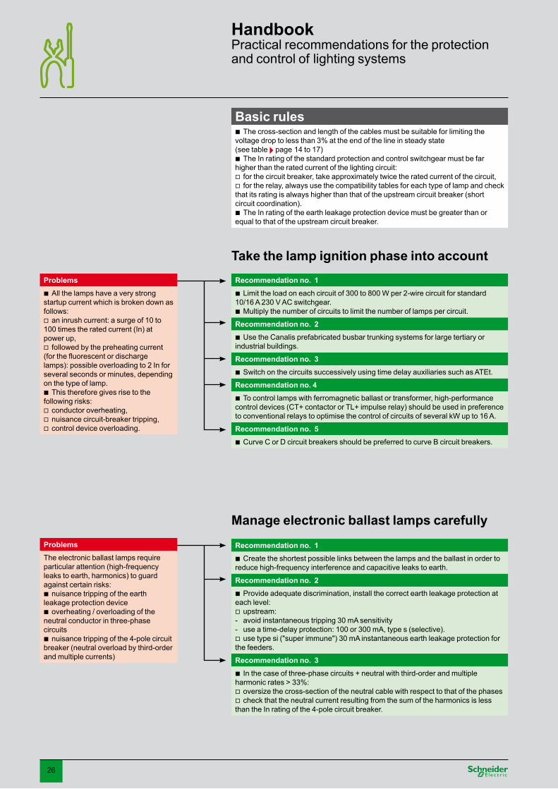
26
Handbook Practical recommendations for the protection and control of lighting systems
Take the lamp ignition phase into account Problems
All the lamps have a very strong startup current which is broken down as follows:
an inrush current: a surge of 10 to 100 times the rated current (In) at power up,
followed by the preheating current (forthefluorescentordischargelamps): possible overloading to 2 In for several seconds or minutes, depending on the type of lamp.
This therefore gives rise to the following risks:
conductor overheating, nuisance circuit-breaker tripping, control device overloading.
b
v
v
b
vvv
Recommendation no. 1Limit the load on each circuit of �00 to 800 W per 2-wire circuit for standard
10/16 A 2�0 V AC switchgear. Multiply the number of circuits to limit the number of lamps per circuit.
b
b
Recommendation no. 2Use the Canalis prefabricated busbar trunking systems for large tertiary or
industrial buildings. b
Recommendation no. 3Switch on the circuits successively using time delay auxiliaries such as ATEt. b
Recommendation no. 4To control lamps with ferromagnetic ballast or transformer, high-performance
control devices (CT+ contactor or TL+ impulse relay) should be used in preference to conventional relays to optimise the control of circuits of several kW up to 16 A.
b
Recommendation no. 5Curve C or D circuit breakers should be preferred to curve B circuit breakers. b
Basic rules The cross-section and length of the cables must be suitable for limiting the
voltage drop to less than �% at the end of the line in steady state (see table page 14 to 17)
The In rating of the standard protection and control switchgear must be far higher than the rated current of the lighting circuit:
for the circuit breaker, take approximately twice the rated current of the circuit, for the relay, always use the compatibility tables for each type of lamp and check
that its rating is always higher than that of the upstream circuit breaker (short circuit coordination).
The In rating of the earth leakage protection device must be greater than or equal to that of the upstream circuit breaker.
b
b
vv
b
Manage electronic ballast lamps carefully Problems The electronic ballast lamps require particular attention (high-frequency leaks to earth, harmonics) to guard against certain risks:
nuisance tripping of the earth leakage protection device
overheating / overloading of the neutral conductor in three-phase circuits
nuisance tripping of the 4-pole circuit breaker (neutral overload by third-order and multiple currents)
b
b
b
Recommendation no. 1Create the shortest possible links between the lamps and the ballast in order to
reduce high-frequency interference and capacitive leaks to earth. b
Recommendation no. 2Provide adequate discrimination, install the correct earth leakage protection at
each level: upstream: avoid instantaneous tripping �0 mA sensitivity use a time-delay protection: 100 or �00 mA, type s (selective). use type si ("super immune") �0 mA instantaneous earth leakage protection for
the feeders.
b
v--v
Recommendation no. 3In the case of three-phase circuits + neutral with third-order and multiple
harmonic rates > ��%: oversize the cross-section of the neutral cable with respect to that of the phases check that the neutral current resulting from the sum of the harmonics is less
than the In rating of the 4-pole circuit breaker.
b
vv
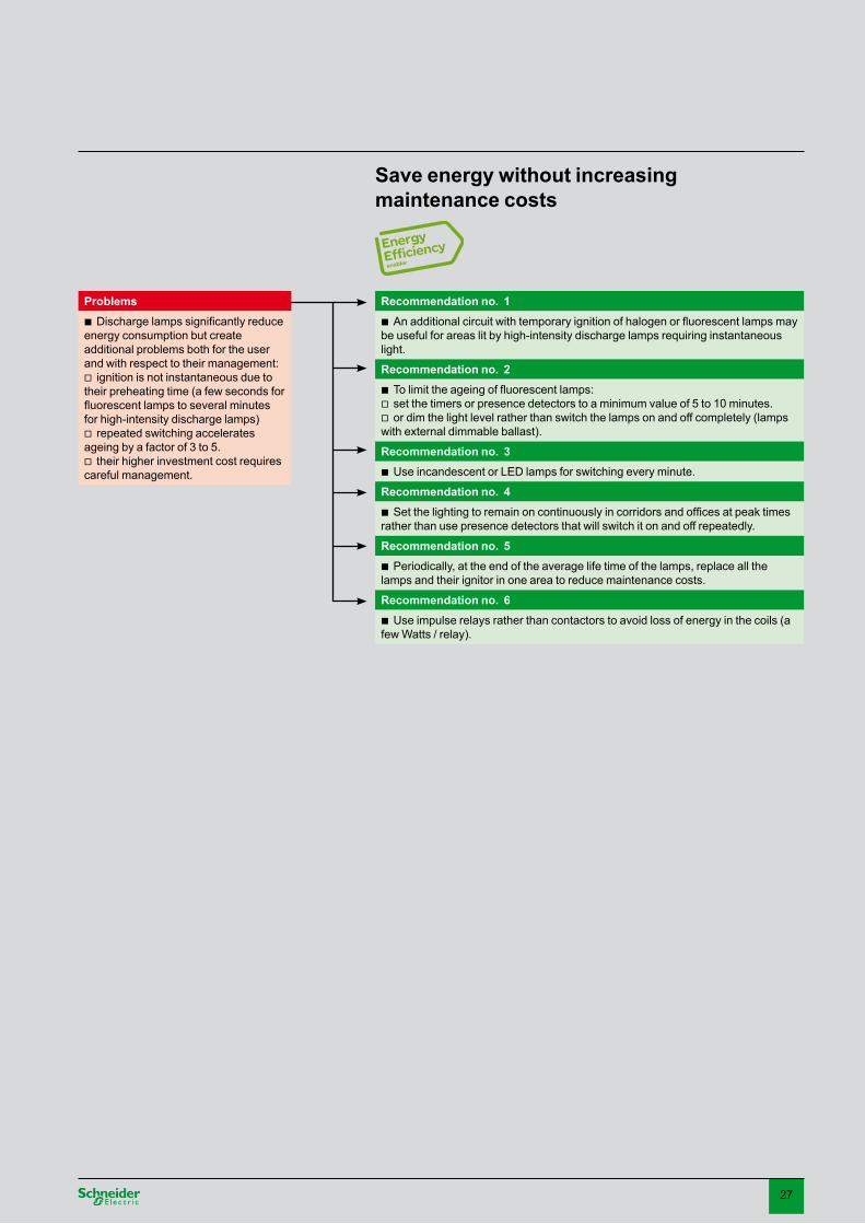
27
Problems Dischargelampssignificantlyreduce
energy consumption but create additional problems both for the user and with respect to their management:
ignition is not instantaneous due to their preheating time (a few seconds for fluorescentlampstoseveralminutesfor high-intensity discharge lamps)
repeated switching accelerates ageing by a factor of � to 5.
their higher investment cost requires careful management.
b
v
v
v
Save energy without increasing maintenance costs
Recommendation no. 1Anadditionalcircuitwithtemporaryignitionofhalogenorfluorescentlampsmay
be useful for areas lit by high-intensity discharge lamps requiring instantaneous light.
b
Recommendation no. 2Tolimittheageingoffluorescentlamps:set the timers or presence detectors to a minimum value of 5 to 10 minutes. or dim the light level rather than switch the lamps on and off completely (lamps
with external dimmable ballast).
bvv
Recommendation no. 3Use incandescent or LED lamps for switching every minute.b
Recommendation no. 4Setthelightingtoremainoncontinuouslyincorridorsandofficesatpeaktimes
rather than use presence detectors that will switch it on and off repeatedly.b
Recommendation no. 5Periodically, at the end of the average life time of the lamps, replace all the
lamps and their ignitor in one area to reduce maintenance costs.b
Recommendation no. 6Use impulse relays rather than contactors to avoid loss of energy in the coils (a
few Watts / relay).b

28
Notes

29

�0
Notes


This document has been printed on ecological paper
Schneider Electric Industries SAS89, boulevard Franklin RooseveltF-92506 Rueil-Malmaison CedexTel: +�� (0)1 41 29 85 00
www.schneider-electric.comwww.merlin-gerin.com
M9 GT 1�/B.en 04-2008
© S
chne
ider
Ele
ctric
- A
ll rig
hts
rese
rved
Asstandards,specificationsanddesignschangefromtimetotime,pleaseaskforconfirmationof the information given in this publication.
Publishing: Schneider ElectricPrinting: Schneider-Electric


