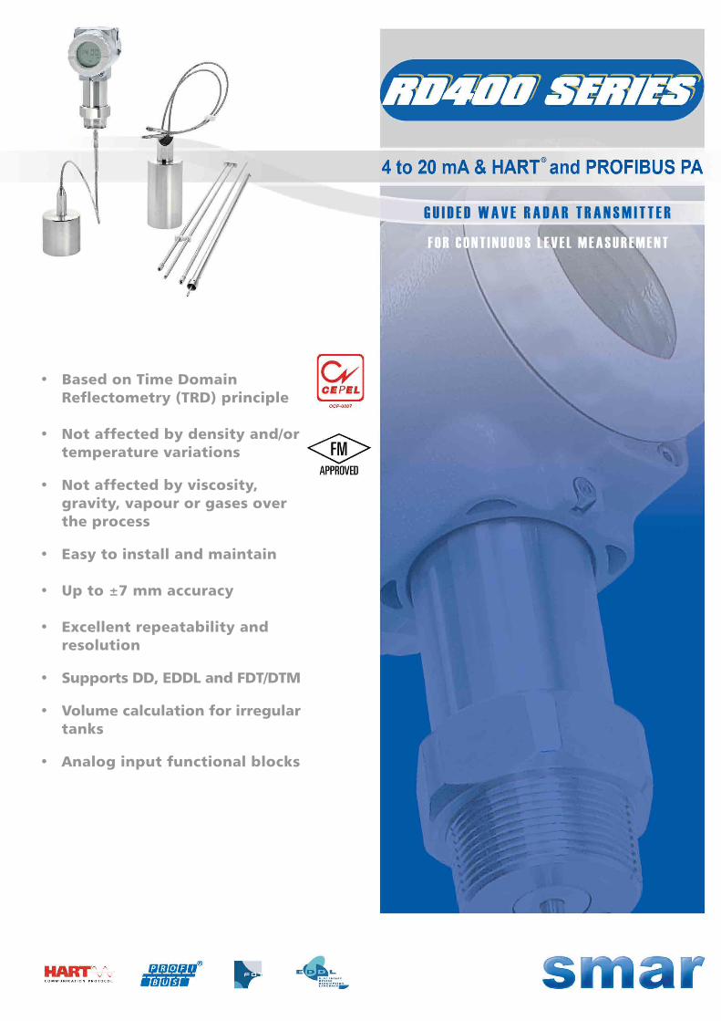
• Based on Time Domain Reflectometry (TRD) principle
• Not affected by density and/or temperature variations
• Not affected by viscosity, gravity, vapour or gases over the process
• Easy to install and maintain
• Up to ±7 mm accuracy
• Excellent repeatability and resolution
• Supports DD, EDDL and FDT/DTM
• Volume calculation for irregular tanks
• Analog input functional blocks
G U I D E D W A V E R A D A R T R A N S M I T T E R
F O R C O N T I N U O U S L E V E L M E A S U R E M E N T

2
Features
Equipment
Housing – Contain all the electronics, local adjustment, electrical connections and Liquid Crystal Display (LCD).
Isolator – Isolates the electronics from the probe, and contains the frequency generator, which emits and receives the waves that will be guided through the probe. Also allows the probe rotation, granting high tensions over it.
Probe – See figure “RD400 Probes”, page 3. The electromagnetic waves are guided through the probe - immersed into middle which level is desired.
RD400 components
• Easy to install and maintain;
• Local adjustment;
• Multifunctional rotative display;
• Sensor Threshold Level for different products;
• Supports DTM and EDDL.
HART® / 4 - 20 mA
PROFIBUS-PA
• Zero and span local adjustment;
• HART® protocol;
• Output current with 1.6 μA resolution;
• Easy to configure by Smar CONF401 and DDCON100 for Windows.
• PROFIBUS-PA protocol;
• Analog input functional block;
• 12 mA consuption;
• Integrated to Smar ProfibusView or Simatic PDM;
• Profile 3.0 improves interchangeability.
3
Technology
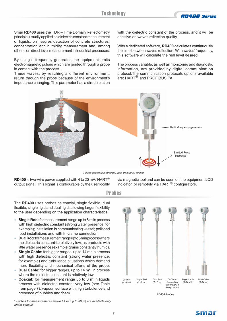
Smar RD400 uses the TDR – Time Domain Reflectometry principle, usually applied on dielectric constant measurement of liquids, on fissures detection of concrete structures, concentration and humidity measurement and, among others, on direct level measurement in industrial processes.
By using a frequency generator, the equipment emits electromagnetic pulses which are guided through a probe in contact with the process.These waves, by reaching a different environment, return through the probe because of the environment’s impedance changing. This parameter has a direct relation
Radio-frequency generator
with the dielectric constant of the process, and it will be decisive on waves reflection quality.
With a dedicated software, RD400 calculates continuously the time between waves reflection. With waves’ frequency, this software will calculate the real level desired.
The process variable, as well as monitoring and diagnostic information, are provided by digital communication protocol.The communication protocols options available are: HART and PROFIBUS PA.
Emitted Pulse (illustrative)
Pulses generation through Radio-frequency emitter
RD400 is two-wire power supplied with 4 to 20 mA/ HART output signal. This signal is configurable by the user locally
via magnetic tool and can be seen on the equipment LCD indicator, or remotely via HART configurators.
ProbesThe RD400 uses probes as coaxial, single flexible, dual flexible, single rigid and dual rigid, allowing larger flexibility to the user depending on the application characteristics. • Single Rod: for measurement range up to 8 m in process
with high dielectric constant (strong water presence, for example); installation in communicating vessel; polished food installations and with tri-clamp connection.
• Dual Rod: for measurement range up to 8 m in process where the dielectric constant is relatively low, as products with little water presence (example:grains constantly humid).
• Single Cable: for bigger ranges, up to 14 m* in process with high dielectric constant (strong water presence, for example) and turbulence situations which demand more flexibility and mechanical efforts of the probe.
• Dual Cable: for bigger ranges, up to 14 m*, in process where the dielectric constant is relatively low.
• Coaxial: for measurement range up to 6 m in liquids process with dielectric constant very low (see Table from page 7), vapour, surface with high turbulence and presence of bubbles and foam.
Coaxial(1 - 6 m)
Dual Rod (1 - 8 m)
Dual Cable (1-14 m*)
Single Rod(1 - 8 m)
Single Cable (1-14 m*)
RD400 Probes
Tri-ClampConnection
with Polished Rod (1 - 4 m)
* Probes for measurements above 14 m (up to 30 m) are available only under consult.

4
Features
Level MeasurementLevels of solids and liquids can be measured with precision in a lot of applications and temperature conditions, tanks geometry no comma etc. The main parameter for the measurement is the dielectric constant of the product (consult our team for more informations about dielectric constants).
Volume CalculationRD400 calculates automatically volumes of typical tanks like vertical and horizontal cylinders or spherical tanks. Other tank shapes can be calculated with a strap table with a maximum of 10 points.
Probe TypesRD400 uses coaxial, single flexible, dual flexible, single rigid (polished with tri-clamp connection or not) and dual rigid, allowing larger flexibility to the user depending on the application characteristics.
AlarmsBesides the saturation alarms of output current 0 (Low) and 100% (High), the RD400 can retains the last reads value, immediately before the equipment indicates this condition, entering in alarm mode.
Local AdjustmentMany RD400 parameters can be changed by using the local adjustment via magnetic tool – like range limits and tank configuration, for example.
Upper and Bottom Blocking DistancesRD400 can be configured to not consider distances at the top and at the bottom of the probe. It is very useful when internal obstacles generate noises which can interfere on the waves signal. Also, the equipment’s upper (up to 50 cm) and bottom (up to 20 cm) dead zones must be considered.
The 0 and 100% points are set over the probe
UpperDead Zone
(up to 30 cm)
UpperBlockingDistance
(up to 20 cm)
BottomBlockingDistance
BottomDead Zone
BottomBlockingDistance
BottomDead Zone
(up to 20 cm)

5
Applications
Electromagnetic Field over each Probe
RD400 measures process levels like:• Various powdered and granular solids;• Semi-solids;• Liquids based or not on water.
The measurement will basically depend on the minimum dielectric constant of the process. This measurement generally not depend on density and temperature changing, foam on the surface, agitation, viscosity, and most part of internal obstacles which usually generate false echoes to non-contact radars and ultra-sounds.
Many tanks already have sockets at their upper part, in order to install equipments or simply verify the process. RD400 can be installed at these sockets, which is an advantage, considering that the structure will not be perforated again. RD400 installation can be done by communicating vessel or over the tank (top mounting).
In underground tanks, for example, the access to them can be unviable sometimes, so hydrostatic pressure
transmitters become inapplicable. In this case, top mounting equipments are recommended.
For each process, its dielectric constant value and the type of RD400 probe must be known to grant a better performance on the measurement.
Top Mounting Installation in Communicating Vessel
Coaxial
Contained wave swithou t externalinterferences
Dual Prob eSingle Prob e(with metal sheet / �ange)
Aplications
6
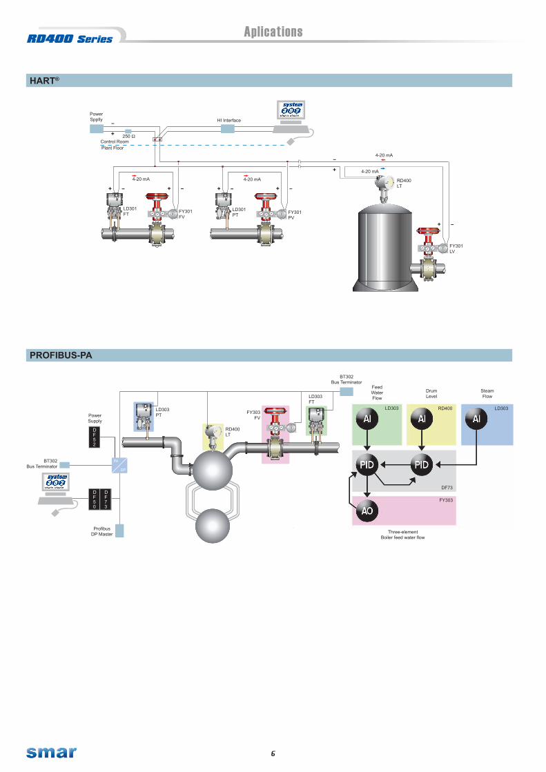
HART®
PROFIBUS-PA
4-20 mA
4-20 mA
FY301PV
LD301PT
Control Room
HI Interface
FY301LV
RD400LT
4-20 mAPlant Floor
4-20 mA
FY301FV
LD301FT
PowerSpplly
250
73
DF
DF50
DF52
FeedWaterFlow
LD303 RD400
FY303
DrumLevel
SteamFlow
Three-elementBoiler feed water flow
DF73
LD303
LD303FT
FY303FV
LD303PT
RD400LT
ProfibusDP Master
PowerSupply
PA
BT302Bus Terminator
DP
BT302Bus Terminator
Technical Characteristics
7
Functional Specifications
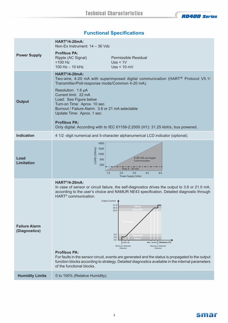
HART®/4-20mA:Two-wire, 4-20 mA with superimposed digital communication (HART Protocol V5.1/Transmitter/Poll-response mode/Common 4-20 mA).
Resolution: 1.6 μA Current limit: 22 mA Load: See Figure below Turn-on Time: Aprox. 10 sec. Burnout / Failure Alarm: 3.6 or 21 mA selectable Update Time: Aprox. 1 sec.
Profibus PA:Only digital. According with to IEC 61158-2:2000 (H1): 31.25 kbit/s, bus powered.
HART®/4-20mA:Non-Ex Instrument: 14 – 36 Vdc
Profibus PA:Ripple (AC Signal) Permissible Residual <100 Hz Uss < 1V100 Hz – 10 kHz Uss < 10 mV
Output
Power Supply
4 1/2 -digit numerical and 5-character alphanumerical LCD indicator (optional).Indication
LoadLimitation LO
AD
(Ohm
s)
1650
1500
1000
500
250
1 2 2 0 3 0 4 0 4 5Power Supply (Volts)
4-20 mA and DigitalCommunication
Only 4 - 20 mA
HART®/4-20mA:In case of sensor or circuit failure, the self-diagnostics drives the output to 3.6 or 21.0 mA, according to the user’s choice and NAMUR NE43 specification. Detailed diagnostic through HART® communication.
Output Current
21.020.520.0
4.03.83.6
FailureSaturated
Set Range
SaturatedFailure
-1.25% 0% 100% 103.25% Distance (%)
Minimum DetectedDistance
Maximum DetectedDistance
Failure Alarm (Diagnostics)
Profibus PA:For faults in the sensor circuit, events are generated and the status is propagated to the output function blocks according to strategy. Detailed diagnostics available in the internal parameters of the functional blocks.
Humidity Limits 0 to 100% (Relative Humidity).
8
Technical Characteristics
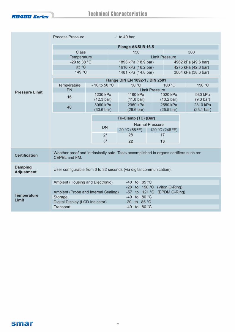
Process Pressure -1 to 40 bar
Temperature Limit PressureClass 150 300
149 °C
Flange ANSI B 16.5
1618 kPa (16.2 bar)1481 kPa (14.8 bar)
4962 kPa (49.6 bar)
3864 kPa (38.6 bar)
1893 kPa (18.9 bar)-29 to 38 °C93 °C 4275 kPa (42.8 bar)
Pressure Limit PN Limit PressureTemperature
Flange DIN EN 1092-1 / DIN 2501- 10 to 50 °C 50 °C 100 °C 150 °C
16 1230 kPa(12.3 bar)
1180 kPa(11.8 bar)
1020 kPa(10.2 bar)
930 kPa(9.3 bar)
40 3060 kPa(30.6 bar)
2960 kPa(29.6 bar)
2550 kPa(25.5 bar)
2310 kPa(23.1 bar)
Normal Pressure
3"
Tri-Clamp (TC) (Bar)
2822
120 °C (248 ºF)20 °C (68 ºF)DN
1713
2"
DampingAdjustment User configurable from 0 to 32 seconds (via digital communication).
Certification Weather proof and intrinsically safe. Tests accomplished in organs certifiers such as:CEPEL and FM.
TemperatureLimit
Ambient (Housing and Electronic) -40 to 85 °C -28 to 150 °C (Viton O-Ring) Ambient (Probe and Internal Sealing) -57 to 121 °C (EPDM O-Ring)Storage -40 to 80 °CDigital Display (LCD Indicator) -20 to 85 °CTransport -40 to 80 °C
9
Technical Characteristics
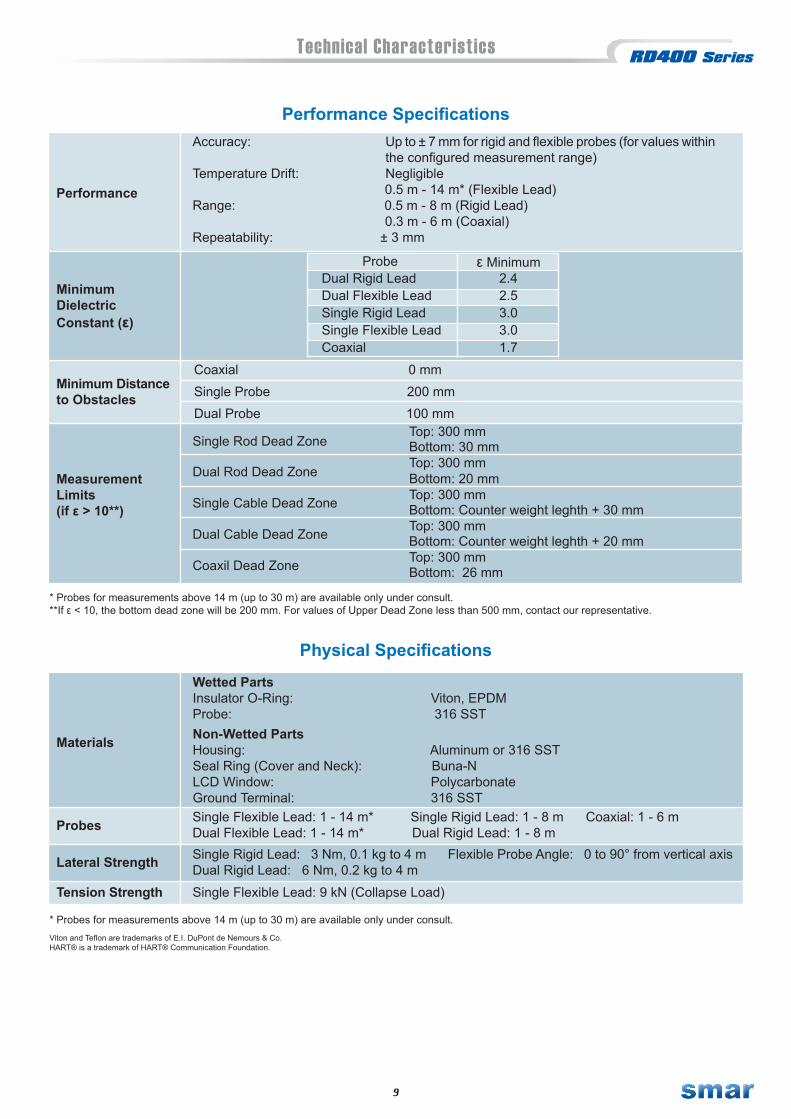
Performance SpecificationsAccuracy: Up to ± 7 mm for rigid and flexible probes (for values within the configured measurement range)Temperature Drift: Negligible 0.5 m - 14 m* (Flexible Lead)Range: 0.5 m - 8 m (Rigid Lead) 0.3 m - 6 m (Coaxial)Repeatability: ± 3 mm
Performance
MinimumDielectricConstant (ε)
Probe ε MinimumDual Rigid LeadDual Flexible LeadSingle Rigid LeadSingle Flexible LeadCoaxial
2.42.53.03.01.7
Minimum Distance to Obstacles
Coaxial 0 mmSingle Probe 200 mmDual Probe 100 mm
Measurement Limits (if ε > 10**)
Top: 300 mm Bottom: 30 mmTop: 300 mm Bottom: 20 mmTop: 300 mm Bottom: Counter weight leghth + 30 mm Top: 300 mm Bottom: Counter weight leghth + 20 mmTop: 300 mm Bottom: 26 mm
Single Rod Dead Zone Dual Rod Dead Zone
Single Cable Dead Zone
Dual Cable Dead Zone
Coaxil Dead Zone
* Probes for measurements above 14 m (up to 30 m) are available only under consult.**If ε < 10, the bottom dead zone will be 200 mm. For values of Upper Dead Zone less than 500 mm, contact our representative.
Physical Specifications
Materials
Wetted Parts Insulator O-Ring: Viton, EPDMProbe: 316 SSTNon-Wetted Parts Housing: Aluminum or 316 SST Seal Ring (Cover and Neck): Buna-N LCD Window: Polycarbonate Ground Terminal: 316 SST
Probes Single Flexible Lead: 1 - 14 m* Single Rigid Lead: 1 - 8 m Coaxial: 1 - 6 m Dual Flexible Lead: 1 - 14 m* Dual Rigid Lead: 1 - 8 m
Lateral Strength Single Rigid Lead: 3 Nm, 0.1 kg to 4 m Flexible Probe Angle: 0 to 90° from vertical axis Dual Rigid Lead: 6 Nm, 0.2 kg to 4 m
Tension Strength Single Flexible Lead: 9 kN (Collapse Load)
Viton and Teflon are trademarks of E.I. DuPont de Nemours & Co.HART® is a trademark of HART® Communication Foundation.
* Probes for measurements above 14 m (up to 30 m) are available only under consult.
8
HP
HART®
PROFIBUS PA
RD400 00 I0H 11 I 11 B A *0 0 00
Notes:
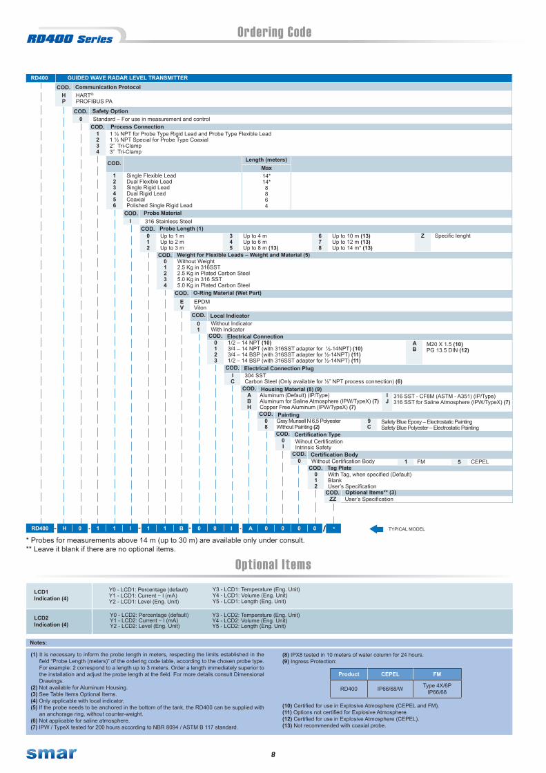
Ordering Code
M20 X 1.5 (10)PG 13.5 DIN (12)
AB
GUIDED WAVE RADAR LEVEL TRANSMITTER
COD. Communication Protocol
1234
COD. Process Connection1 ½ NPT for Probe Type Rigid Lead and Probe Type Flexible Lead1 ½ NPT Special for Probe Type Coaxial2” Tri-Clamp 3” Tri-Clamp
RD400
COD.
Single Flexible LeadDual Flexible LeadSingle Rigid LeadDual Rigid LeadCoaxial Polished Single Rigid Lead
123456
COD. Probe Material 316 Stainless Steel I
COD. Probe Length (1)012
COD. Weight for Flexible Leads – Weight and Material (5)Without Weight2.5 Kg in 316SST2.5 Kg in Plated Carbon Steel5.0 Kg in 316 SST5.0 Kg in Plated Carbon Steel
01234
COD. O-Ring Material (Wet Part)EPDMViton
EV
COD. Local IndicatorWithout IndicatorWith Indicator
01
COD. Electrical Connection1/2 – 14 NPT (10)3/4 – 14 NPT (with 316SST adapter for ½-14NPT) (10)3/4 – 14 BSP (with 316SST adapter for ½-14NPT) (11)1/2 – 14 BSP (with 316SST adapter for ½-14NPT) (11)
0123
COD. PaintingGray Munsell N 6,5 PolyesterWithout Painting (2)
08
0COD. Safety Option
Standard – For use in measurement and control
Length (meters)Max14*14*8864
COD. Electrical Connection PlugIC
COD. Housing Material (8) (9)Aluminum (Default) (IP/Type)Aluminum for Saline Atmosphere (IPW/TypeX) (7)Copper Free Aluminum (IPW/TypeX) (7)
ABH
COD. Certification TypeWihout CertificationIntrinsic Safety
0I
COD. Certification BodyWithout Certification Body0
COD. Tag PlateWith Tag, when specified (Default)BlankUser’s Specification
012
COD. Optional Items** (3)User’s SpecificationZZ
304 SSTCarbon Steel (Only available for ½” NPT process connection) (6)
Up to 10 m (13)Up to 12 m (13)Up to 14 m* (13)
678
Up to 1 mUp to 2 m Up to 3 m
345
Up to 4 m Up to 6 m Up to 8 m (13)
316 SST - CF8M (ASTM - A351) (IP/Type)316 SST for Saline Atmosphere (IPW/TypeX) (7)
IJ
Safety Blue Epoxy – Electrostatic PaintingSafety Blue Polyester – Electrostatic Painting
9C
FM1 CEPEL5
TYPICAL MODEL
* Probes for measurements above 14 m (up to 30 m) are available only under consult.** Leave it blank if there are no optional items.
Optional ItemsLCD1Indication (4)
Y0 - LCD1: Percentage (default)Y1 - LCD1: Current − l (mA)Y2 - LCD1: Level (Eng. Unit)
LCD2Indication (4)
Y0 - LCD2: Percentage (default)Y1 - LCD2: Current − l (mA)Y2 - LCD2: Level (Eng. Unit)
Y3 - LCD1: Temperature (Eng. Unit)Y4 - LCD1: Volume (Eng. Unit)Y5 - LCD1: Length (Eng. Unit)
Y3 - LCD2: Temperature (Eng. Unit)Y4 - LCD2: Volume (Eng. Unit)Y5 - LCD2: Length (Eng. Unit)
(1) It is necessary to inform the probe length in meters, respecting the limits established in the field “Probe Length (meters)” of the ordering code table, according to the chosen probe type. For example: 2 correspond to a length up to 3 meters. Order a length immediately superior to the installation and adjust the probe length at the field. For more details consult Dimensional Drawings.
(2) Not available for Aluminum Housing.(3) See Table Items Optional Items.(4) Only applicable with local indicator.(5) If the probe needs to be anchored in the bottom of the tank, the RD400 can be supplied with
an anchorage ring, without counter-weight.(6) Not applicable for saline atmosphere.(7) IPW / TypeX tested for 200 hours according to NBR 8094 / ASTM B 117 standard.
(8) IPX8 tested in 10 meters of water column for 24 hours.(9) Ingress Protection:
(10) Certified for use in Explosive Atmosphere (CEPEL and FM).(11) Options not certified for Explosive Atmosphere.(12) Certified for use in Explosive Atmosphere (CEPEL).(13) Not recommended with coaxial probe.
Product CEPEL FM
RD400 IP66/68/W Type 4X/6PIP66/68
Specific lenghtZ

9
Ordering Code Dimensional Drawings
Dimensions in milimeters (inches) Dimensions in milimeters (inches)
Dimensions in milimeters (inches)Dimensions in milimeters (inches)
SINGLE RIGID LEAD
125
Ø83
(3.24)82.5
193
Ø6.35(Ø0.25)
MIN.1000 (39.37)MAX.8000 (314.96)
(2.1
2)
(4.92)
(Ø3.
26)
(7.6
)
54
TERMINALCONNECTION
ELECTRICALCONNECTION
THREAD 1-1/2 NPT
Dimensions in milimeters (inches)
DUAL RIGID LEAD
(3.24)82.5125
(4.92)
193
(Ø3.
26)
Ø83
Ø6.35(Ø0.25)
(Ø0.25)Ø6.35
(7.6)
(2.1
2)54
MIN. 1000 (39.37)MAX. 8000 (314.96)
TERMINALCONNECTION
ELECTRICALCONNECTION
THREAD 1-1/2 NPT
Dimensions in milimeters (inches)
82.5
(Ø3.
26)
Ø83
Ø22. 2
(Ø0.15)Ø4
97THREAD 1.1/2-NPT
(3.24)(4.92)125
MAX.14000(551.2)MIN.1000 (39.3)
(3.8
)
(Ø0.875)
193
(7.6
)
70 (2.7
5)
70
(2.7
5)
(Ø3")Ø76.2
TERMINALCONNECTION
ELECTRICALCONNECTION
125
Ø83
Ø38
Ø4(Ø0.15)
(4.92)
(Ø3.
26)
Ø4(Ø0.15)
(Ø1.5)
70(2
.75)
82.5(3.24)
97 (3.8
)
193
(7.6
)
MAX.14000 (551.2)MIN.1000(39.3)
(Ø3")
70(2
.75)
Ø76.2
THREAD 1.1/2-NPT
TERMINALCONNECTION
ELECTRICALCONNECTION
SINGLE RIGID LEAD DUAL RIGID LEAD
SINGLE FLEXIBLE CABLE DUAL FLEXIBLE CABLE
* Probes for measurements above 14 m (up to 30 m) are available only under consult

10
Dimensional Drawings
Dimensions in milimeters (inches)Dimensions in milimeters (inches)
Dimensions in milimeters (inches)
6 236.22
125
Ø83
(3.24)82.5
193
Ø6.35(Ø0.25)
MIN. 1000 (39.37)
(2.1
2)
(4.92)
(Ø3.
26)
(7. 6
)
54
MAX.4000 (157.5)
Ø"A"2" Ø63.5
Ø91
TC
3"
Ø"A"
Dimensions in milimeters (inches)
TERMINALCONNECTION
ELECTRICALCONNECTION
POLISHED SINGLE RIGID LEADTRI CLAMP CONNECTION
152.4
165.1
"ØA"
ANSI-B 16.5
150 lb.
300 lb.
150 lb.
CLASSDN
3"
2"
2"
" ØA "
125
Ø8
3
82.5(3.24)(4.92)
(Ø3.
26)
100
50 PN 10/40
PN 10/40
PN 10/16
DIN 2501/2528
165
220
300 lb.
150 lb.
3"
4" 228.6
209.5
190.5
4" 300 lb. 254
279.4150 lb.6"
100 PN 25/40 235
80 200
PN 16 285150
"ØA"
(11)
(10)
(7.5)
(8.25)
(9)
(6.5)
(6)
(11.2)
(9.25)
(8.6)
(6.5)
(7.8)
150(5.9)
178
(7. 0
)
318300 lb.6" (12.5)
"ØA"CLASSDN "ØA"
FLANGE MOUNTING
Dimensions in milimeters (inches)
TERMINALCONNECTION
ELECTRICALCONNECTION
MINIMUM FOR LOCALZERO AND SPANADJUSTMENT
THREAD 1-1/2 NPT
COAXIAL POLISHED SINGLE RIGID LEADTRI CLAMP CONNECTION
FLANGE MOUNTING

11
Mai
nten
ance
- MES
(Man
ufac
turin
g Ex
ecut
ion
Syst
em)
- ERP
(Ent
erpr
ise R
esou
rce
Plan
ning
)- C
RM (C
usto
mer
Rel
atio
nshi
p M
anag
emen
t)
All-i
n-on
e St
atio
n
Engi
neer
ing
Mai
nten
ance
Ope
ratio
n
Mai
nten
ance
and
As
set M
anag
emen
t
Alar
m a
nd E
vent
Man
agem
ent
Auto
Tun
ing
Adva
nced
Con
trol
Rout
er o
rFi
rewa
llCorp
orat
e N
etw
ork
Inte
rnet
Inte
rnet
Fisc
alPr
inte
r
Prin
ter
Pack
age
Units
Lega
cy S
yste
ms
CLP
F&G
ESD
DFI3
02(C
ontro
ller w
ith I/
O m
odul
es)
I.S.
Disc
rete
I/O
4 - 2
0 m
A I.S
.
Disc
rete
I/O
4 - 2
0 m
A
DFI3
02AS
-i
DFI3
02De
viceN
et
Com
mun
icatio
nSe
rver
Com
mun
icatio
nSe
rver
DFI3
02PR
OFI
BUS
DP a
nd P
A
DPPA
Com
mun
icatio
nSe
rver
Ethe
rnet
HI30
2HA
RT/F
OUN
DATI
ON
TM
DFI3
02Re
dund
ant C
ontro
llers
Com
mun
icatio
nSe
rver
Com
mun
icatio
nSe
rver
DFI3
02Re
dund
ant C
ontro
llers
Fibe
r O
ptic
Ring
DF10
0
4 - 20 mAOutputs
4 - 20 mAInputs
Intri
nsic
Safe
tyBa
rrier
F OUN
DATI
ON
FISC
O
TM
DC30
2(R
emot
e I/O
)
In D
iscre
teOu
t Disc
rete
FOUN
DATI
ON
H
1 I.S
.
TM
Chan
nel 1
Chan
nel 8
2t
20tp0 pu
mutsmA
s
TCP
and
RTU
Data
base
Redu
ndan
t Ser
vers
SYSTEM302 Architecture

12
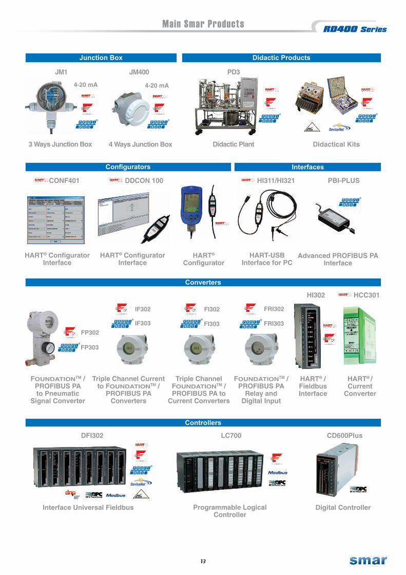
Main Smar Products
Pressure
Position
Pressure Transmitter
"In Line"
LD291
LD292
LD293
4-20 mA LD290
Pressure Transmitter
LD301
LD302
LD303
LD400
Pressure Transmitterwith High
Performance
FY301
FY302
FY303
TP301
TP302
TP303
Valve Positioner with Remote Sensor
PositionTransmitter
Temperature
TemperatureTransmitter
TT301
TT302
TT303
Panel MountingTemperatureTransmitter
TT411
Head MoutingTemperatureTransmitter
TT421
Pressure, Level and Flow
LD1.0
Gauge EconomicCapacitivePressure
Transmitter
Guided WaveLevel Transmitter
RD400
Intelligent Density /Concentration
Transmitter
DT301
DT302
DT303
Level Density/Concentration Position
FY301
FY302
FY303
FY400
ValvePositioner
Valve Positionerwith Auto Tuning
Pressure and Level
FlangedTransmitter
PressureTransmitter with Extended Probe
WirelessHARTPressure
Transmitter
Pneumatic LinearCylindric Actuador
Pneumatic RotaryCylindric Actuador
Eight InputTemperatureTransmitter
SmartTemperatureTransmitter
WirelessHARTTemperatureTransmitter
LD291
LD292
LD293
4-20 mA LD290LD291
LD292
LD293
4-20 mA LD290LD400
ACP301
ACP302
ACP303
ACP301
ACP302
ACP303
TT383 TT400TT400 HART® SIS
4-20 mA TP290ACP400
ACP400
FY400
13
Main Smar Products
Converters
FOUNDATIONTM /PROFIBUS PAto Pneumatic
Signal Converter
FP302
FP303
Triple Channel Currentto FOUNDATIONTM /
PROFIBUS PAConverters
IF302
IF303
HART® /FieldbusInterface
HART® /Current
Converter
Triple ChannelFOUNDATIONTM /PROFIBUS PA to
Current Converters
FI302
FI303
Controllers
Programmable Logical Controller
Digital Controller
Advanced PROFIBUS PAInterface
HART-USBInterface for PC
InterfacesConfigurators
HART® ConfiguratorInterface
HART®
ConfiguratorHART® Configurator
Interface
Junction Box
3 Ways Junction Box
4-20 mA
4 Ways Junction Box
4-20 mA
Interface Universal Fieldbus
TM
DeviceNet
Didactic Products
Didactic Plant Didactical Kits
FOUNDATIONTM / PROFIBUS PA
Relay andDigital Input
TM
DeviceNet
FRI302
FRI303
JM1 JM400 PD3
CONF401 DDCON 100 HI311/HI321 PBI-PLUS
HI302 HCC301
DFI302 LC700 CD600Plus

T T 4 0 0 W H C P
Main Smar Products
SimulationViewControl Strategy Simulator
ProcessViewSupervision / Operation System
AssetView STANDALONEAsset Management System
SYSTEM302
TM
DeviceNet
Process Equipment DatabasePlant Information Management
SysconControl Strategy and
Industrial Network Configurator
LogicView for FFBIEC61131 Programming Tool
Controllers - Remote Input and Output
FOUNDATIONTM fieldbus / PROFIBUS PARemote Input and Output
HSE Controller andWirelessHART Gateway
smarSpecifications and information are subject to change without notice.
Up-to-date address information is available on our website.
web: www.smar.com/contactus.asp
www.smar.com
DF100 DC303 DC302
©Copyright 2007 - Smar International - all rights reserved. - November/2012


