Download - Guzzler Parts Catalog

Industrial Vacuum and Vacuum ExcavationParts & Accessories


iToll Free: 800-822-8785
Table of ContentsModel and Serial Number .................................. viManuals ......................................................... viii
A HOSESTuff Guzz Hose ............................................... A-1Tuff Guzz Hose Assembly ................................. A-1Green Monster Hose ...................................... A-2Green Monster Hose Assembly ......................... A-2AR Kanaflex Hose ........................................... A-3HR Kanaflex Hose Assembly ............................. A-4Plastic Hose .................................................... A-5Metal Flex Hose .............................................. A-5Boom Hose .................................................... A-6Debris Hose ................................................... A-6SafeVac Combo Hose ...................................... A-7Expansion Joint ............................................... A-7
B BAGS & CAGESCartridge Filter Advantages ...............................B-1Changing Filter Bage& Cartridge Filters ..............B-2Filter Bag Selection Guide .................................B-3Catridge Fill ....................................................B-4Retainer Sleeve ................................................B-4Dacron Filter Bag ............................................B-4Acrylic-Coated Filter Bag ...................................B-5Nomex Filter Bag .............................................B-5Super Seal Bag ................................................B-5Filter Bag Cage ...............................................B-6
C VACUUM HOSE FITTINGS Coupler Assemblies ......................................... C-1Weld-On Female Coupler ................................ C-1Hose-End Female Coupler ................................ C-1Weld-On Male Coupler ................................... C-2Hose-End Male Coupler ................................... C-2Y-Adapter ....................................................... C-23-Way Adapter ............................................... C-390-Degree Elbow ............................................ C-345-Degree Elbow ............................................ C-3Reducer ......................................................... C-4Adapter Weldment .......................................... C-4Male-End Plug ................................................ C-5Female-End Plug .............................................. C-5Tee-Adapter .................................................... C-5
Wet Ring........................................................ C-5Water Ring ..................................................... C-5In-Line Vacuum Relief Valve ............................... C-6Camlock Dust Cap .......................................... C-6Camlock Dust Plug .......................................... C-6Camlock Male-to-Female NPT ........................... C-7Camlock Male-to-Male NPT .............................. C-7Camlock Female-to-Male Reducer .................... C-7Camlock Female-to-Female NPT ........................ C-8Camlock Hose Shank ...................................... C-8
D VACUUM TUBINGSteel Tubing with Bandlock Ends .......................D-1Aluminum Tubing with Bandlock Ends .................D-1Aluminum Pipe Assembly with Flanged Ends ........D-2Aluminum Nozzle Handle .................................D-2Aluminum Nozzle Assembly ..............................D-2
E CLAMPSDouble Bolt Clamp ...........................................E-1Coupler Clamp ................................................E-1T-Bolt Clamp ....................................................E-1Power Clamp ................................................... E-2Quick Clamp ................................................... E-2Expansion Plug ................................................ E-2Cage Long ......................................................E-3Cage Short .....................................................E-3
F NOZZLESEasy Lift Nozzle ............................................... F-1Backbone Nozzle ............................................ F-1Long-Reach Nozzle ......................................... F-2Shovel Nozzle ................................................. F-2Pit-Cleaning Nozzle.......................................... F-2Production Nozzle............................................ F-3Bulk Nozzle .................................................... F-3Floor Nozzle ................................................... F-3
G GASKETS Clean-out Door Gasket ....................................G-1Top Baghouse Door Gasket .............................G-1Poured Gasket Material....................................G-1Linear Wall Clean-out Door Gasket ................... G-2

ii E-mail: [email protected]
Cyclone Door Gasket....................................... G-2Dump Chute Door Gasket ............................... G-2Rear Inspection Door Gasket ............................ G-2D-Ring Gasket ................................................ G-2Half-Opening Tailgate Gasket ..........................G-3Door Seal ......................................................G-3Full-Opening Tailgate Gasket ............................G-3Expansion Joint Gasket ....................................G-3Coupler Gasket ...............................................G-4Profile Gasket ................................................G-4Camlock Gasket .............................................G-4Blower-to-Silencer Expansion Joint .....................G-4Microstrainer-to-Blower Expansion Joint ..............G-4Flange Gasket ................................................G-5Boom Blind Flange Gasket ...............................G-5Blower Gasket ................................................G-5Rubber “U” Strap ............................................G-5Float Ball Shut-Off Rubber Seat. ........................G-5Slip Ring for Silencer .......................................G-6Gasket for VRB System .....................................G-6Blower Expansion Joint Hose ............................G-6Make/Break Seal ............................................G-6Inspection Port Gasket ......................................G-6
H ELECTRICALShift Tower Relay............................................. H-1Relay Socket ................................................... H-1Pressure Switches ............................................ H-1Wireless Control Unit ....................................... H-2Radio Control Unit ........................................... H-2Vacuum Relief Pendant .................................... H-3Boom Pendants ............................................... H-4Control Panel Assembly (New Style) .................. H-5Vibrator ......................................................... H-6Electric-Over-Air Solenoid Valve......................... H-6Switches ......................................................... H-6Throttle Cable ................................................. H-7Lights ............................................................. H-7Vacuum Switch ................................................ H-7Pressure Protection Valve .................................. H-8Circuit Breaker ................................................ H-8Tach Sensor .................................................... H-8Relay ............................................................. H-8Air Pressure Sender ......................................... H-93-Position Throttle Switch .................................. H-9Blower Temperature Sending Unit ...................... H-9
Temperature Sending Unit Boot ......................... H-9Air Solenoid Manifold Bank ........................... H-10Solenioid ...................................................... H-10Air Solenoid ................................................. H-10Replacement Solenoid Kit ............................... H-10Retrofit Instructions for Air Solenoid Replacement H-11Push-Pull Maintained Switch ............................ H-12Joystick ........................................................ H-12Wiring Harness ............................................ H-12
I HYDRAULICTailgate Cylinder ...............................................I-1Hoist Cyclinder .................................................I-1Tailgate Manifold Assembly ..............................I-1Hydraulic Pump ................................................. I-2Variable-Volume Pressure-Compensated Pump ....... I-2Control Valve ................................................... I-2Hydraulic Cylinders ...........................................I-3Hydraulic Filters ................................................I-3Filter Breather Assembly .....................................I-3Hydraulic Tank ..................................................I-3Boom Motor .....................................................I-4Boom Cylinder .................................................I-4Hydraulic Lock Assembly ....................................I-4Tailgate Lock ....................................................I-4Shuttle Valve .....................................................I-4Sandwich Valve ................................................I-4Solenoid Valve ..................................................I-5Subplate for Solenoid Valves ..............................I-5Hoist Cylinder Controls ......................................I-5Vibrator ..........................................................I-6Recommended Practices for Handling & Storage of Hydraulic Components ....................................... I-7Recommended Start-up Procedure for New or Rebuilt Pump or Motor..................................................I-8Troubleshooting .................................................I-9
J GAUGESSight Glasses ................................................... J-1Hydraulic Tank Spare Parts ................................ J-1Tachometer Gauges ..........................................J-2Hydraulic Gauges .............................................J-2Vacuum Gauges ...............................................J-2Temperature Guages ........................................ J-3Pressure Gauges .............................................. J-3

iiiToll Free: 800-822-8785
Table of ContentsMagnehelic Gauges ......................................... J-4Blower Temperature Gauges .............................. J-4
K VALVESBrass Lever Gate Valve .....................................K-1Valve Handle ..................................................K-1Brass Ball Valve ...............................................K-1Butterfly Valve (Air-Actuated) ..............................K-2Actuator ..........................................................K-2Disc Seal Kit ....................................................K-2Valve Body Assembly ........................................K-2Valve Seal Kit ..................................................K-2Butterfly Valve (Manual) ....................................K-3Knifegate Valve ................................................K-3Knifegate Valve (Air-Actuated) ............................K-3Knifegate Valve (Manual) ..................................K-3Dezurik Valve ..................................................K-4Dezurik Valve Blade .........................................K-4Dezurik Valve Packing ......................................K-4Dezurik Valve Seats ..........................................K-4Kunkle Valve ....................................................K-5Safety Screen Basket (for Vacuum Relief Valve) .....K-5Directional Control Valve ...................................K-5Air Fitting Manifold ..........................................K-6Air Filter ..........................................................K-6Air Valve .........................................................K-7Air Shifter .......................................................K-7
L PULSATION/PNEUMATICAir Cannon Solenoid ........................................ L-1Air Cannon Tank .............................................. L-1Air Cannon Retrofit Kit (Classic) ......................... L-1Air Cannon Retrofit Kit (ACE) ............................. L-1Pressure Transducer ...........................................L-2Relay ...............................................................L-2Skinner Valve ....................................................L-2Solenoid Valve ................................................. L-3Diaphragm Valve ............................................. L-3Field Modification of Air Cannon ....................... L-4
M BODY PARTSCyclone Insert Assembly ...................................M-145-Degree Porthole Elbow ................................M-270-Degree Boom Elbow ...................................M-2
Elbows ...........................................................M-2Porthole Inlet Tube ...........................................M-3JR Wing Deflector ...........................................M-3Classic Baghouse Door ................................... M-4Classic Cyclone Door ..................................... M-4Classic Linear Wall Door ................................ M-4Clean-out Door .............................................. M-4Dump Chute Door ...........................................M-5Dump Chute Door Plunger ................................M-5ACE Baghouse Door Lid ...................................M-5ACE Cyclone Door Lid .....................................M-5ACE Door Clamp ............................................M-5Rear Float Level Indicator .................................M-6Side-Mounted Float Level Indicator ....................M-6Float Level Indicator .........................................M-7Float Ball (Stainless Steel) .................................M-7Float Ball (Mild Steel) .......................................M-7Float Ball Cage (Mild Steel) ..............................M-7Silencer .........................................................M-8Microstrainer ..................................................M-9Microstrainer Basket ........................................M-9Boom — Miscellaneous Parts ............................M-9Boom Box ....................................................M-10ACE Tank Outlet Assembly .............................M-10Bag Hold-Down Assembly ..............................M-10Tailgate Safety Pin .........................................M-11Tailgate Safety Prop ......................................M-11Debris Tank Safety Stand ...............................M-11Tailgate Shim ................................................M-11Pin-Wheel Latch ............................................M-11Elbow Installation ..........................................M-12Make/Break Installation .................................M-12Spring Strut Assembly ....................................M-12Vacuum Relief Valve ......................................M-13Vibrator Basket .............................................M-13Transfer Case Driveline Cover .........................M-13Static Ground Reel ........................................M-13Isolator ........................................................M-14Groove Coupler ............................................M-14Butterfly Latch ...............................................M-14Fender Light Bracket ......................................M-14Rear Bumper.................................................M-15Mud Flap .....................................................M-15Cooling Fan .................................................M-15Tie Down .....................................................M-16ACE Fenders.................................................M-16

iv E-mail: [email protected]
Table of Contents
N BLOWERSRoots Blowers ................................................N-1Robuschi Blowers ............................................ N1Hibon Blowers ...............................................N-1Holmes Blowers .............................................N-1Rebuilt Blowers ..............................................N-1Filter Element ..................................................N-2Heat Shield ...................................................N-2Foot Gasket ....................................................N-2Foot Spring ....................................................N-2Keystock .........................................................N-2
O TRANSFER CASEDana Transfer Case (Complete Unit) ..................O-1Cotta Transfer Case (Complete Unit) ..................O-1OMSI Transfer Case (Complete Unit) .................O-1Transfer Case Brackets .....................................O-2Companion Flange ..........................................O-2Isolator ..........................................................O-2OMSI Transfer Case (Parts detail) ......................O-3
P WATER PUMPWater Pump .................................................... P-110 gpm .......................................................... P-220 gpm ..........................................................P-4
Q SLUDGE PUMPPump Head ....................................................Q-14” (101 mm) Sludge Pump (Parts Detail) .............Q-26" (152 mm) Sludge Pump (Parts Detail) ............Q-4
R DRIVELINEDana Driveline Assembly ..................................R-1OMSI-Hibon Driveline Assembly .........................R-1Cotta and OMSI Transfer Case .......................... R-2Upper Driveline ................................................ R-2Driveshaft Assembly .......................................... R-2Bore Flange ..................................................... R-2
S DECALSDecal Kits ........................................................S-1NX Logo .........................................................S-1
ACE Logos ......................................................S-1Classic Logos ...................................................S-1HXX Logos.......................................................S-2
T HXX REPLACEMENT PARTSAlkota Water Heater ........................................ T-1Hotsy Water Heater ......................................... T-4Domed Hotsy Hood .......................................... T-4Heating Coil .................................................... T-4Fuel Nozzle ..................................................... T-4Fuel Solenoid ................................................... T-4Burner Gasket .................................................. T-4Burner Motor ................................................... T-4Hotsy Water Heater (Parts Detail) ....................... T-5Photo Cell ....................................................... T-6Fuel Filter Assembly .......................................... T-6Fuel Pump ....................................................... T-6Thermostat Control ........................................... T-6Primary Control ................................................ T-6Power Switch ................................................... T-7Flow Switch ..................................................... T-7Ignitor Transformer ........................................... T-7Electrode ......................................................... T-7Relay .............................................................. T-7Hose .............................................................. T-8Final Filter ....................................................... T-8Air filter. .......................................................... T-8Seal Kit ........................................................... T-9Valve Kit ......................................................... T-9Valves ............................................................. T-9Spider ............................................................ T-9Ignition Switch ................................................. T-9Digging Lance Kit ........................................... T-10Quick-Disconnect ............................................ T-10Safety Shutoff Valve Assembly ......................... T-10Rotator Nozzle .............................................. T-11Nozzle with Guard Assembly .......................... T-11Nozzle Tube Guard ....................................... T-11CAT Pump ..................................................... T-11
U SAFETY SUPPLIESRain Suits ....................................................... U-1Tyvek® Suits .................................................... U-1Steel Toe Rubber Boots .................................... U-1Gloves ........................................................... U-2
vToll Free: 800-822-8785
Table of ContentsHard Hat ....................................................... U-2Face Shield .................................................... U-2Safety Glasses ................................................ U-2Ear Plugs ........................................................ U-2Duct Tape....................................................... U-3Non-Skid Equi Mat .......................................... U-3Tool Box......................................................... U-3
V MAINTENANCERecommended Oils, Lubricants & Fuels ...............V-1
W INDEXIndex by Part Number ..................................... W-1
3M, International, Teflon, Tyvek, and Viton are trademarked and/or registered trade names of their respective companies. Federal Signal Corporation disclaims any and all rights to these marks.
Federal Signal Corporation reserves the right to suspend or discontinue the sale of any product contained herein or perform any modifications to product design without prior notification.

vi E-mail: [email protected]
Locate Your Unit Identity PlateThis page will help you locate the identity plate that contain’s your units Model No. and Serial No. Lo-cate this information now and insert if in the appropriate blanks within the Guzzler or HXX name plates below. That way, it will always be readily accessible to help ensure you get the right components and parts on every order.
Model and Serial Number
GUZZLER ACE/CLASSICLocation is the same on all versions.
Call us if you have a problem locating the identity plate.
Aluminum control box location Composite control box location
Note: 2011 and newer units all have the tag in the same general location on the driver side on the front part of the subframe. Options may obscure direct viewing.
Old style New style
viiToll Free: 800-822-8785
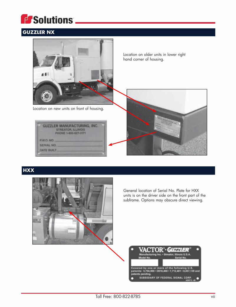
GUZZLER NX
Location on new units on front of housing.
Location on older units in lower right hand corner of housing.
HXX
General location of Serial No. Plate for HXX units is on the driver side on the front part of the subframe. Options may obscure direct viewing.

viii E-mail: [email protected]
ManualsGuzzler and FS Solutions are your partners in working smart and safeAll manuals pertaining to unit operation and safety can be ordered using the part numbers shown. These part numbers are for all 2006 units and newer. All older units, or units not listed, should be ordered under Part No. 500655.
Model and serial numbers are required when ordering (see “locate Your Unit Identity Plate” on vii).
Part No. Manual Description500646 Vactor/Guzzler Safety500647 WJTA Waterblast
Safety500650 Guzzler Off-loading
options2006 and newer. Covers ACE, Classic and NX options.
500651 Ramjet 2006 and newer. Covers all models and normal options.500654 Guzzler ACE and
Classic2006 and newer. Covers all models. Liquid ring models are now an option section.
500655 Replacement Manual Use this number for all units prior to 2006 or not listed here. Requires model and serial number. Also note if in Spanish.
500657 WJTA Recommeneded Practices for The Use of Industrial Vacuum Equipment
Available January 2008
503081 2100 Blower 2006 and newer. Includes all normal options.503082 2100 Fan 2006 and newer. Includes all normal options.503085 GRV 2006 and newer. Covers model with fliud coupling drive.503086 2103 Spanish 2006 and newer. Includes all normal options.503087 2103 2006 and newer. Includes all normal options.503088 I-12000 Fan 2006 and newer. Includes all normal options.503089 I-600 Blower 2006 and newer. Includes all normal options.503090 HXX Fan 2006 and newer. Includes all normal options.503091 HXX Blower 2006 and newer. Includes all normal options.503095 Guzzler NX 2006 and newer. Includes all normal options.503096 HXX Prodigy 2006 and newer. Includes all normal options.503223 2100 Operator
Training BookCovers blower and fan operation, service and maintenance and most options but no parts. Includes safety manual. Printed in black and white and bound in a report cover. Excelllent low cost manual to leave in the unit for reference.
88385# Chassis Manuals 88385# series, see system for all.KH0026C Predator
(Liquid Vacuum Truck)2009 and newer. Includes all options.
ixToll Free: 800-822-8785
Manuals
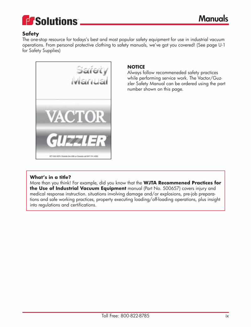
SafetyThe one-stop resource for todays’s best and most popular safety equipment for use in industrial vacuum operations. From personal protective clothing to safety manuals, we’ve got you covered! (See page U-1 for Safety Supplies)
NOTICEAlways follow recommeneded safety practices while performing service work. The Vactor/Guz-zler Safety Manual can be ordered using the part number shown on this page.
What’s in a title?More than you think! For example, did you know that the WJTA Recommened Practices for the Use of Industrial Vacuum Equipment manual (Part No. 500657) covers injury and medical response instruction. situations involving damage and/or explosions, pre-job prepara-tions and safe working practices, property executing loading/off-loading operations, plus insight into regulations and certifications.


Hoses
A-1Toll Free: 800-822-8785
Air leaks in hose connections, inlet connections and around gaskets can disrupt your entire vacuum operation. Air leaks can cause excess baghouse loading, greater fuel consumption, and poor pickup performance at the end of the hose. Air leaks decrease the air velocity at the end of the hose causing material to “fall out” in the hose where material buildup may eventually clog the hose. By using the highest quality hoses and connections, you will help prevent air leaks and keep your vacuum operation running at optimum efficiency.
Tuff Guzz HoseRugged, flexible, smooth-bore rubber vacuum hose with helix coil. Rated to 27" Hg. Temperature range: -40° to 220°F (-40° to 104°C)
Part No. Description1280403 4" x 20' (101 mm x 6.1 m) hose
only1280404 6" x 10' (152 mm x 3 m) hose
only1280489 6” x 14’ (152 mm x 4.3 m)
hose only1280694 6” 17’6” (152 mm x 5.3 m)
hose only1280405 6" x 20' (152 mm x 6.1 m) hose
only1280406 8" x 10' (203 mm x 3 m) hose
only1280419 8" x 20' (203 mm x 6.1 m) hose
only
Tuff Guzz Hose AssemblyPart No. Description1280414 4" x 20' (101 mm x 6.1 m)
with male & female hose ends1280415 6" x 10' (152 mm x 3 m)
with male & female hose ends1280416 6" x 20' (152 mm x 6.1 m)
with male & female hose ends1280417 8" x 10' (203 mm x 3 m)
with male & female hose ends1280418 8" x 20' (203 mm x 6.1 m)
with male & female hose ends1280489 6" x 14' (152 mm x 4.3 m) used
on XCR Cyclone units with male & female hose ends
1280694 6" x 17'6" (152 mm x 5.3 m) used on XCR Cyclone units with male & female hose ends

Hoses
A-2 E-mail: [email protected]
Green Monster Hose Heavy-duty, abrasion-resistant, smooth-bore, 3/8" (9.53 mm) gum rubber-lined hose with helix coil. Rated to 27" Hg. Temperature range: -40° to 220°F (-40° to 104°C)
Part No. Description1280461 4" (101 mm) x (sold per foot) used
in high-abrasion applications.1280920 6" (152 mm) x (sold per foot) used
in high-abrasion applications.1280463 8”( 203 mm) x (sold per foot) used
in high-abrasion applications. Recommended for boom and port hole tail hose.
Green Monster Hose Assembly
Part No. Description1280460 4" x 20' (101 mm x 6.1 m)
with male & female hose ends1280928 6" x 6' (152 mm x 1.8 m)
with male & female hose ends1280691 6” x 10’ (152 mm x 3 m)
with male & female hose ends1280691A 6" x 20' (152 mm x 6.1 m)
with male & female hose ends1280882 8” x 5’ (203 mm x 1.5 m)
with chain & irregular hose ends1280582 8" x 8' (203 mm x 2.4 m)
with male & female hose ends1280458 8" x 10' (203 mm x 3 m)
with male & female hose ends1280463J 8” X 16’ (203 mm x 4.9 m)
with male & female hose ends1280757 8” x 20' (203 mm x 6.1 m)
with male & female hose ends

Hoses
A-3Toll Free: 800-822-8785
180 AR HosesHeavy-duty abrasion-resistant suction hose handling abrasives such as crushed rock, sand, pea gravel, cement powder, dry fertilizer, iron ore and grains. Temperature range: -40° to 158°F (-40° to 70°C).
Part No. Description1280229 4" (101 mm) x (sold per foot) -
180 AR 1280228 6" (152 mm) x (sold per foot) -
180 AR
AR Kanaflex Hose
Part No. Description1280343 4" x 20' (101 mm x 6.1 m) -
180 AR with male & female hose ends
1280344 6" x 10' (152 mm x 3 m) - 180 AR with male & female hose ends
1280345 6" x 20' (152 mm x 6.1 m) - 180 AR with male & female hose ends
1280230 6” X 25’ 152 mm x 7.6 m) - 180 AR with male & female hose ends
501001 10" x 4.5' (253 mm x 1.4 m) - 180 AR with male & female ends
AR Kanaflex Hose Assembly
Construction:• SBR rubber blended with static, carbon-black, rigid PVC helix coil• Smooth-bore• Corrugated O.D.
Features:
• Lightweight and flexible• Static dissipating • Extremely abrasion-resistant • Rated to 27" Hg

Hoses
A-4 E-mail: [email protected]
180 HR HosesHeavy-duty, abrasion-resistant suction hose for applications where higher temperatures and abrasion are factors such as handling of fly ash, crushed rock, sand, pea gravel or cement powder. Temperature range: -40° to 220°F (-40° to 104°C).
Part No. Description1280346 4" (101 mm) x (sold per foot) -
180 HR 1280347 6" (152 mm) x (sold per foot) -
180 HR1280315 8" (203 mm) x (sold per foot) -
180 HR
HR Kanaflex Hose
Part No. Description1280339 4" x 20' (101 mm x 6.1 m) -
180 HR with male & female hose ends
52350 6" x 10' (152 mm x 3 m) - 180 HR with male & female hose ends
1280341 6" x 20' (152 mm x 6.1 m) - 180 HR with male & female hose ends
1280669 8" x 8' (203 mm x 2.4 m) - 180 HR with male & female hose ends
1280464 8" x 10' (203 mm x 3 m) - 180 HR with male & female hose ends
1280636 8" x 20' (203 mm x 6.1 m) - 180 HR with male & female hose ends
HR Kanaflex Hose Assembly
Construction:• EPDM rubber• Polyethylene helix• Metal helical wire• Smooth-bore
Features:• Lightweight and flexible• Integral wire helix can be grounded• Provides easy drag

Hoses
A-5Toll Free: 800-822-8785
Plastic HoseLightweight, plastic disposable hose designed for use as the last section of hose to which the vacuum nozzle is attached.
Part No. Description1280122 4" (101 mm) x (sold per foot)
black plastic. Comes in 100' (30.4 m) sections.
1280188 6" (152 mm) x (sold per foot) black plastic. Comes in 100' (30.4 m) sections.
1280188A 6" (152 mm) smooth-bore plastic. Sold in 20' (6.1 m) sections.
1280122A 4" (101 mm) x (sold per foot) yellow plastic. Comes in 100’ (30.4 m) sections.
1280188C 6" (152 mm) x (sold per foot) yellow plastic. Comes in 100' (30.4 m) sections (Fig. 1)
1280189 8" (203 mm) x (sold per foot) black plastic. Comes in 20' (6.1 m) sections.
Metal Flex HoseComposed of galvanized steel, this heavy-duty, abrasion-resistant, rough-bore, flexible hose should be used when vacuuming high temperature materials. Maximum operating temperature: 500°F (260°C).
Part No. Description1280367 Hose 4” x 25’, galvanized inter-
lock metal flex w/o ends. 1280600 Hose 6” x 25’, galvanized
rough bore metal flex, 500 Deg. F
40732A 4" x 25' (101 mm x 7.6 m) with ends — comes in 25' (7.6 m) sections with ends.
1280862A 6" x 25' (101 mm x 7.6 m) with ends — comes in 25' (7.6 m) sections with ends.
1280822A 8” Hose 8”, steel flex.
Fig. 1
The yellow plastic hose is longer lasting and more durable than the black plastic hose.
Related Items
See Section F for recommended Nozzles or hose-handling accessories.

Hoses
A-6 E-mail: [email protected]
Part No. Description70404E 8" x 34" (203 mm x 863 mm)
red rubber, gum-lined (HXX Units)43958A 8" x 136" (203 mm x 3.45 m)
red rubber hose, gum-lined (extendable boom - HXX Units)
46564D 8" x 60" (203 mm x 1.52 m) red rubber, gum-lined (telescopic boom - HXX Units)
70404H 8" x 37" (203 mm x 940 mm) red rubber, gum-lined (HXX Units)
46564 8” x 62” (203 mm x 1574 mm) standard rubber
70404M 8” x 37” (203 mm x 940 mm)red rubber, gum-lined, 30” HG
70404F 8” x 18” (203 mm x 440 mm) red rubber, gum-lined , 30” HG
46564G 8” x 62” (203 mm x 1.57 m) red rubber, gum-lined
46564N 8” x 60” (203 mm x 1.52 m) Dura-Shield
501077B 12” x 21” (305 mm x .53 m)rubber
Debris Hose
Boom HoseSmooth-bore boom hose used on Guzzler Ramrodder units.
Part No. Description1280166 8" x 54" (203 mm x 1371 mm)1280457 8" x 24" (203 mm x 609 mm)54428C 8” x 60” (203 mm x 1.52 m) assy.
redlined47394 10” x 10’ hose46449 10” x 66”

Hoses
A-7Toll Free: 800-822-8785
Part No. Description1250191 8" (203 mm) Flex-fast —
27" Hg maximum vacuum1250028 10" (254 mm), 11.8125" OD x
10.8125" ID (300 mm x 274.6 mm)1250029 12" (305 mm), 13.875" OD x
12.875" ID (352.4 mm x 327 mm)
Expansion JointRequires double bolt clamp (see Section E)
SafeVac Combo HosePart No. Description1287037 9.25” x 60” w/ special cuff (For
Boom)


Bags & Cages
B-1Toll Free: 800-822-8785
Keep filter bags clean and free of tears for effective and efficient filtration. Faulty bags can produce premature blower wear from heat and debris. Guzzler’s complete line of filters for wet and dry applications provide effective solutions to meet the ongoing changes in regula-tions and environmental issues. Always use factory recommended filtration to ensure long product life.
Cartridge Filter Advantages: Formed-in-place, cartridge filters feature anchored pleat tips to ensure evenly spaced and straight pleat alignment – critical to proper cleaning and dust discharge. Cartridge filters also offer many other advantages over conventional filters:• require less air pressure to pulse clean • dramatically reduce air-to-cloth ratio• operate across a wide range of • reduce operating pressure differential
temperatures and applications • substantially reduce installation time• 2-3 times more filtration area

Bags & Cages
B-2 E-mail: [email protected]
Changing Filter Bags and Cartridge Filters — The filters inside the baghouse are one of two types – 1) plain cloth filter, or 2) pleated cartridge filter. Both kinds of filters require certain steps that must be followed when changing.
Use the top access door to change either filter type.1. Open the baghouse door on either type unit. The door can be opened by releasing the latches on
each side of the door. Lift up on the latch handle. Now the door can be raised from its horizontal position to a vertical position. It will come to rest in a nearly vertical position.
2. Raise the blow pipe to a vertical position so as to allow access to the filters. The blow pipe is hinged on the far side.
3. Follow the steps below for either Plain Cloth Filter Bags or Pleated Cartridge Filters:
Plain Cloth Filter Bags 1) The top of the filter bags can now be viewed. Inside each bag, a metal cage stretches the length of
the filter to keep the bag from collapsing during vacuuming operations. Lift the cage straight up so as to clear the filter bag. Set the cage aside.
2) Remove the snap ring bag from the tube sheet by pinching the ring partially closed so it can col-lapse, fall through the opening, and land in the bottom of the baghouse for later removal.
3) Install the new bag firmly in the tube sheet by lowering it into the same hole. 4) Ensure that the lip of the snap ring is secured around the entire perimeter. If there are any gaps, the
bag could become dislodged. 5) Replace the metal cage inside the new filter bag by slowly lowering it into the filter bag until it
firmly rests on top of the new snap ring bag. 6) Check the door gasket for wear or damage — replace if necessary. Otherwise, wipe the
gasket clean and remove all foreign matter. The gasket must be clean to form a tight seal against the baghouse seal face to prevent leaks.
7) Close and secure the baghouse door. Lower the door and secure the door latches. 8) Remove the old filter bag now lying in the bottom of the baghouse. Locate the side access door at
the bottom of the baghouse. Release the clean-out door latch and remove the old filter bag. The filter bag should be properly and safely discarded.
Pleated Cartridge Filters Note: There is no steel cage to remove since the cartridge filter is stiff enough to keep it from collapsing during
vacuuming operations.
1) Remove the metal snap ring on the top of the cartridge filter by pulling on the attached loop. Set the ring aside for reinstallation after the new cartridge filter is in place.
2) Partially pinch the ring on top of the cartridge filter to free the lip from the tube sheet. 3) Pull the filter straight up. Do not let it fall into the baghouse. If the cartridge filter falls
into the bottom of the baghouse, it will be difficult to remove from the bottom access door due to its rigid nature.
4) Install the new cartridge filter in the reverse manner as outlined above.

Bags & Cages
B-3Toll Free: 800-822-8785
Filter Bag Selection Guide
Fiber
Maximum Operating
Temperature Acid Resistance
Alkali Resistance
Dry Heat Resistance
Wet Heat Resistance
Flex & Abrasion Resistance
ºF ºC
Polyester 300 149 Good Good Good Good Very GoodPolypropylene 200 93 Excellent Excellent Fair Fair Very GoodAcrylic 284 140 Excellent Fair Good Good FairNomex (Aramid) 425 218 Fair Excellent Excellent Excellent Very GoodNylon 248 120 Fair Excellent Good Good ExcellentGlass 550 288 Good Fair Excellent Excellent PoorCotton 200 93 Poor Fair Fair Fair Good
Polyester (Dacron)Polyester fabrics offer good resistance to most acids, oxidizing agents and organic solvents. Concentrated sulph-uric acid and nitric acids are the exception. Polyesters are dissolved by alkalies at high concentrations. Maximum operating temperature: 300ºF (149 ºC).PolypropylenePolypropylene fabrics offer good tensile strength and abrasion resistance. They perform well in organic and mineral acids, solvents and alkalies. Polypropylene is attacked by nitric and chlorosulphonic acids, sodium and potassium hydroxide at high temperatures and concentrations. Maximum operating temperature: 200ºF (93ºC).AcrylicThe resistance of homopolymer acrylic fibers is excellent in organic solvents, good in oxidizing agents, mineral and organic acids and fair in alkalies. They dissolve in sulphuric acid concentrations. Maximum operating temperature: 266ºF (130ºC.)Nomex (Aramid)Nomex nylon fabrics resist attack by mild acids, mild alkalies and most hydrocarbons. Resistance to sulfur oxides above the acid dew point at temperatures above 300ºF (149ºC) is better than polyester. Flex resistance of No-mex is excellent. Maximum operating temperature: 425ºF (218ºC).NylonNylon fabrics have good tensile strength and alkali resistance. However, nylon is degraded by mineral acids and oxidizing agents. This reaction is accelerated at high concentrations and temperatures. Maximum operating temperature: 248ºF (120ºC).GlassGlass fabrics offer outstanding performance in high heat applications. They are completely resistant to acids except hydrofluoric and hot phosphoric in their most concentrated forms, but are attacked by strong alkalies at room temperature and weak alkalies at higher temperatures. Glass is vulnerable to damage caused by abrasion and flex. Maximum operating temperature: 550ºF (288ºC).CottonCotton fabrics have good abrasion resistance and mechanical strength. They are however subject to rot, mildew and shrinkage. Maximum operating temperature: 200ºF (93ºC).

Bags & Cages
B-4 E-mail: [email protected]
Cartridge Filter (Fig. 1)Maximum operating temperature is 375°F (191°C). Only used in select ACE models.
Part No. Description1260076 57" x 6.25" (1448 mm x 158.75
mm) pleated cartridge filter
Retainer Sleeve (Fig. 2)
Part No. Description11219019 Used with cartridge filter 1260076
Fig. 1
Fig. 2Dacron Filter Bag (5 micron)Standard bag 5 micron with super seal.Maximum operating temperature: 300°F (149°C).
Part No. Description1260037 60" (1524 mm) used in ACE units,
quantity 68 or 72. Call with serial number to confirm. (Fig.3)
1260038 70" (1778 mm) used in Classic and NX units. Classic units hold 60 filter bags. NX units hold 72 filter bags.
1260073 60" x 6.25" (1524 mm x 158.75 mm) — alternative to cartridge filter.
1260011 42" (1067 mm) with ground wire1260033 60" (1524 mm) with ground wire1260018 70” (1778 mm) with ground wire
Dacron Filter Bag1 micron with super seal. Maximum operating temperature: 300°F (149°C).
Part No. Description1260047 60" (1524 mm)1260048 70" (1778 mm)
Fig. 3
Bags & Cages
B-5Toll Free: 800-822-8785
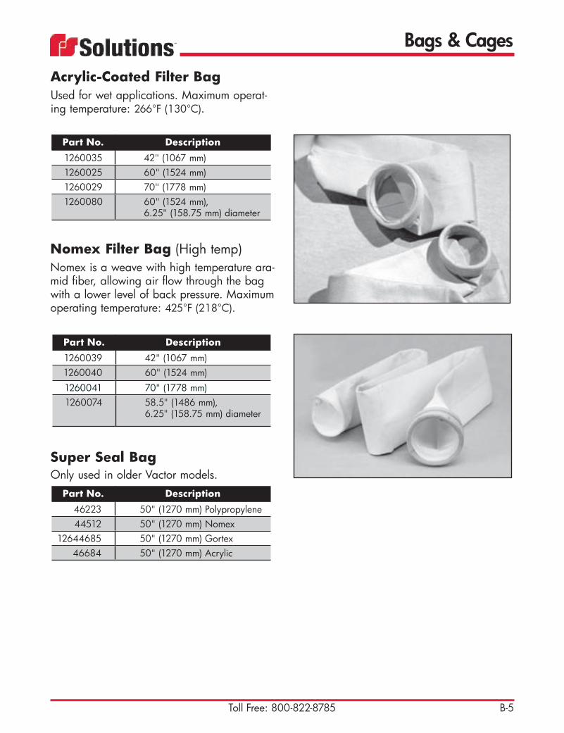
Acrylic-Coated Filter BagUsed for wet applications. Maximum operat-ing temperature: 266°F (130°C).
Part No. Description1260035 42" (1067 mm)1260025 60" (1524 mm)1260029 70" (1778 mm)1260080 60" (1524 mm),
6.25" (158.75 mm) diameter
Nomex Filter Bag (High temp)Nomex is a weave with high temperature ara-mid fiber, allowing air flow through the bag with a lower level of back pressure. Maximum operating temperature: 425°F (218°C).
Part No. Description1260039 42" (1067 mm)1260040 60" (1524 mm)1260041 70" (1778 mm)1260074 58.5" (1486 mm),
6.25" (158.75 mm) diameter
Super Seal Bag Only used in older Vactor models.
Part No. Description46223 50" (1270 mm) Polypropylene44512 50" (1270 mm) Nomex
12644685 50" (1270 mm) Gortex46684 50" (1270 mm) Acrylic
Bags & Cages
B-6 E-mail: [email protected]
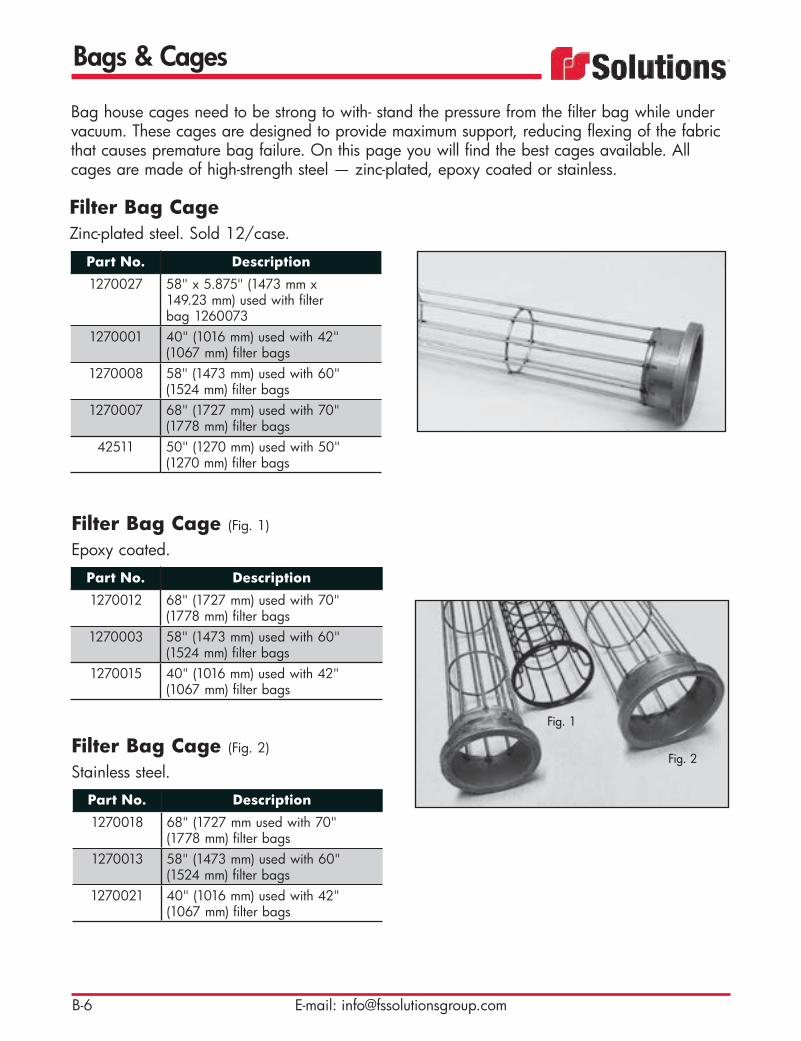
Filter Bag CageZinc-plated steel. Sold 12/case.
Part No. Description1270027 58" x 5.875" (1473 mm x
149.23 mm) used with filter bag 1260073
1270001 40" (1016 mm) used with 42" (1067 mm) filter bags
1270008 58" (1473 mm) used with 60" (1524 mm) filter bags
1270007 68" (1727 mm) used with 70" (1778 mm) filter bags
42511 50" (1270 mm) used with 50" (1270 mm) filter bags
Filter Bag Cage (Fig. 2)
Stainless steel.
Part No. Description1270018 68" (1727 mm used with 70"
(1778 mm) filter bags1270013 58" (1473 mm) used with 60"
(1524 mm) filter bags1270021 40" (1016 mm) used with 42"
(1067 mm) filter bags
Filter Bag Cage (Fig. 1) Epoxy coated.
Part No. Description1270012 68" (1727 mm) used with 70"
(1778 mm) filter bags1270003 58" (1473 mm) used with 60"
(1524 mm) filter bags1270015 40" (1016 mm) used with 42"
(1067 mm) filter bags
Fig. 2
Fig. 1
Bag house cages need to be strong to with- stand the pressure from the filter bag while under vacuum. These cages are designed to provide maximum support, reducing flexing of the fabric that causes premature bag failure. On this page you will find the best cages available. All cages are made of high-strength steel — zinc-plated, epoxy coated or stainless.

Vacuum Hose Fittings
C-1Toll Free: 800-822-8785
Coupler AssembliesAssembly includes male end, female end, clamp and gasket.
Part No. Description42577 4" (101 mm)42578 6" (152 mm)42579 8" (203 mm)
Weld-On Female CouplerFemale coupler — bare metal.
Part No. Description42580 4" (101 mm)
42581 6" (152 mm)42582 8" (203 mm)43594 10" (254 mm)
1280026 12" (305 mm)
Hose-End Female CouplerFemale coupler — galvanized.
Part No. Description42580A 4" (101 mm) 42581A 6" (152 mm)42582A 8" (203 mm)
1280014 10" (254 mm)43369 12" (305 mm)
A full range of quality vacuum hose fittings to meet every hose or vacuum configuration possible. Fabricated to tight tolerances, they provide a better fit for easier installation, easier clamping, and fewer leaks.
Related ItemsSee Section E for Clamps.See Page G-4 for Gaskets.
Vacuum Hose Fittings
C-2 E-mail: [email protected]
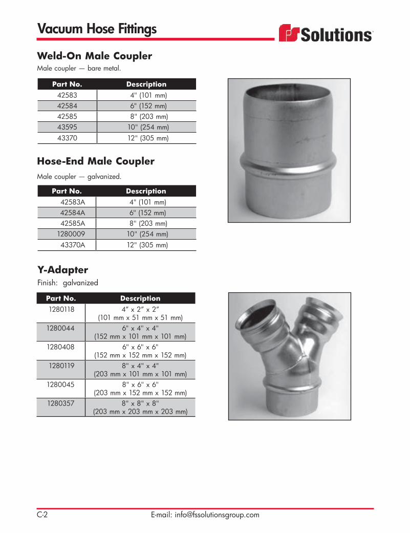
Weld-On Male CouplerMale coupler — bare metal.
Part No. Description42583 4" (101 mm) 42584 6" (152 mm)42585 8" (203 mm)43595 10" (254 mm)43370 12" (305 mm)
Hose-End Male CouplerMale coupler — galvanized.
Part No. Description42583A 4" (101 mm) 42584A 6" (152 mm)42585A 8" (203 mm)
1280009 10" (254 mm)43370A 12" (305 mm)
Y-AdapterFinish: galvanized
Part No. Description1280118 4” x 2” x 2”
(101 mm x 51 mm x 51 mm)1280044 6" x 4" x 4"
(152 mm x 101 mm x 101 mm)1280408 6" x 6" x 6"
(152 mm x 152 mm x 152 mm)1280119 8" x 4" x 4"
(203 mm x 101 mm x 101 mm)1280045 8" x 6" x 6"
(203 mm x 152 mm x 152 mm)1280357 8" x 8" x 8"
(203 mm x 203 mm x 203 mm)

Vacuum Hose Fittings
C-3Toll Free: 800-822-8785
3-Way AdapterFinish: galvanized
Part No. Description1280046 6" x 2" x 2" x 2"
(152 mm x 51 mm x 51 mm x 51 mm)
1280604 6" x 4" x 4" x 4"(152 mm x 101 mm x 101 mm x 101 mm)
1280047 8" x 4" x 4" x 4"(203 mm x 101 mm x 101 mm x 101 mm)
90-Degree ElbowFinish: galvanized
Part No. Description1280032 4" (101 mm) 1280033 6" (152 mm)1280034 8" (203 mm)1280035 10" (254 mm)1280036 12" (305 mm)1280988 6" (152 mm) double wall, bare
steel, for high wear applications1280990 8" (203 mm) double wall, bare
steel, for high wear applications
45-Degree ElbowFinish: galvanized
Part No. Description1280027 4" (101 mm) 1280028 6" (152 mm)1280029 8" (203 mm)1280030 10" (254 mm)1280031 12" (305 mm)1280987 6" (152 mm) double wall, bare
steel, for high wear applications1280989 8" (203 mm) double wall, bare
steel, for high wear applications
Vacuum Hose Fittings
C-4 E-mail: [email protected]
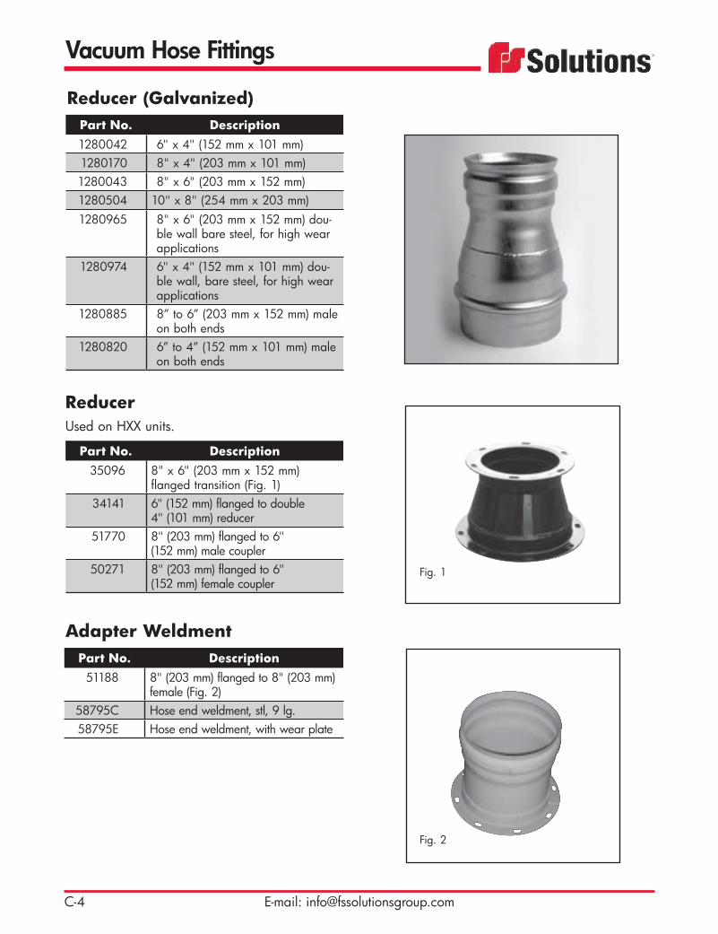
Reducer (Galvanized)Part No. Description1280042 6" x 4" (152 mm x 101 mm)1280170 8" x 4" (203 mm x 101 mm)1280043 8" x 6" (203 mm x 152 mm)1280504 10" x 8" (254 mm x 203 mm)1280965 8" x 6" (203 mm x 152 mm) dou-
ble wall bare steel, for high wear applications
1280974 6" x 4" (152 mm x 101 mm) dou-ble wall, bare steel, for high wear applications
1280885 8” to 6” (203 mm x 152 mm) male on both ends
1280820 6” to 4” (152 mm x 101 mm) male on both ends
Adapter WeldmentPart No. Description
51188 8" (203 mm) flanged to 8" (203 mm) female (Fig. 2)
58795C Hose end weldment, stl, 9 lg.58795E Hose end weldment, with wear plate
ReducerUsed on HXX units.
Part No. Description35096 8" x 6" (203 mm x 152 mm)
flanged transition (Fig. 1)34141 6" (152 mm) flanged to double
4" (101 mm) reducer51770 8" (203 mm) flanged to 6"
(152 mm) male coupler50271 8" (203 mm) flanged to 6"
(152 mm) female couplerFig. 1
Fig. 2
Vacuum Hose Fittings
C-5Toll Free: 800-822-8785
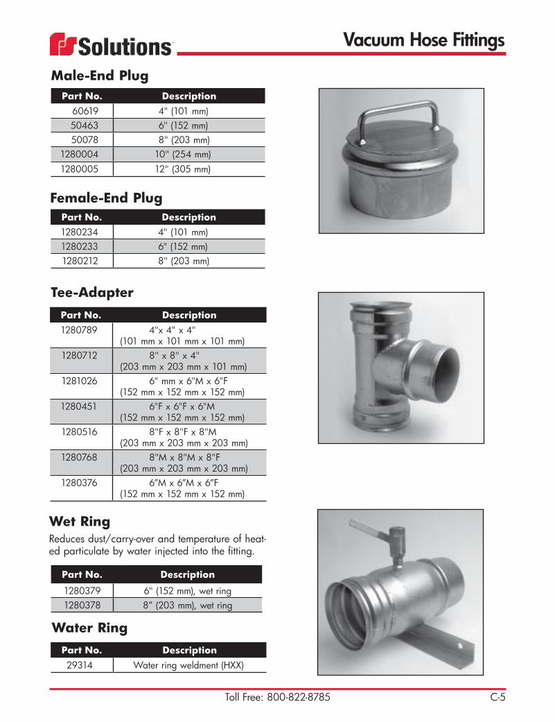
Female-End Plug
Male-End PlugPart No. Description
60619 4" (101 mm) 50463 6" (152 mm)50078 8" (203 mm)
1280004 10" (254 mm)1280005 12" (305 mm)
Tee-AdapterPart No. Description1280789 4"x 4" x 4"
(101 mm x 101 mm x 101 mm)1280712 8" x 8" x 4"
(203 mm x 203 mm x 101 mm)1281026 6" mm x 6"M x 6"F
(152 mm x 152 mm x 152 mm)1280451 6"F x 6"F x 6"M
(152 mm x 152 mm x 152 mm)1280516 8"F x 8"F x 8"M
(203 mm x 203 mm x 203 mm)1280768 8"M x 8"M x 8"F
(203 mm x 203 mm x 203 mm)1280376 6”M x 6”M x 6”F
(152 mm x 152 mm x 152 mm)
Part No. Description1280234 4" (101 mm) 1280233 6" (152 mm)1280212 8" (203 mm)
Wet RingReduces dust/carry-over and temperature of heat-ed particulate by water injected into the fitting.
Water Ring
Part No. Description
1280379 6" (152 mm), wet ring1280378 8” (203 mm), wet ring
Part No. Description29314 Water ring weldment (HXX)

Vacuum Hose Fittings
C-6 E-mail: [email protected]
In-Line Vacuum Relief ValveAlways used between the last section of hose and the nozzle to break the vacuum during emergency situations and normal shut-down.
Part No. Description1280818 4" (101 mm) with male and female
ends1280619 6" (152 mm) with male and female
ends1280760 8" (203 mm) with male and
female ends48457 8" (203 mm) with flanged ends
1280891 4" (101 mm) with camlock ends1280892 6" (152 mm) with camlock ends
Camlock Dust CapAluminum (Fig. 1)
Part No. Description46247B 2" (51 mm)46247D 2-1/2" (63.5 mm)46247A 3" (76 mm)
1280154 4" (101 mm)46229 6" (152 mm)
1280157 8" (203 mm)
Camlock Dust PlugAluminum (Fig. 2)
Part No. Description1280158 2" (51 mm)1280159 2-1/2" (63.5 mm)1280160 3" (76 mm)1280161 4" (101 mm)1280163 6" (152 mm)1280164 8" (203 mm)
Fig. 1
Fig. 2

Vacuum Hose Fittings
C-7Toll Free: 800-822-8785
Camlock Female-to-Male NPTAluminum (Fig. 2)
Part No. Description1280111 2" (51 mm)1280112 2-1/2" (63.5 mm)1280113 3" (76 mm)1280114 4" (101 mm)1280115 6" (152 mm)1280123 8" (203 mm)
Camlock Male-to-Female NPT Aluminum (Fig. 1)
Part No. Description1280104 2" (51 mm)46245D 2-1/2" (63.5 mm)
1280106 3" (76 mm)1280107 4" (101 mm)46245A 6" (152 mm)1280110 8" (203 mm)
Camlock Male-to-Male NPT Aluminum (Fig. 3)
Part No. Description1280144 2" (51 mm)46549D 2-1/2" (63.5 mm)
1280146 3" (76 mm)46858 4" (101 mm)46228 6" (152 mm)
1280150 8" (203 mm)
Fig. 1
Fig. 2
Fig. 3

Vacuum Hose Fittings
C-8 E-mail: [email protected]
Camlock Hose Shank - MaleAluminum (Fig. 4)
Part No. Description1280137 2" (51 mm) Male Adapter46248D 2-1/2" (63.5 mm) Male Adapter
1280139 3" (76 mm) Male Adapter1280140 4" (101 mm) Male Adapter46227A 6" (152 mm) Male Adapter
1280143 8" (203 mm) Male Adapter
Camlock Hose Shank - Female Aluminum (Fig. 3)
Part No. Description1280124 2" (51 mm) Female Adapter1280125 2-1/2" (63.5 mm) Female
Adapter1280126 3" (76 mm) Female Adapter
46248 4" (101 mm) Female Adapter46227 6" (152 mm) Female Adapter
1280130 8" (203 mm) Female Adapter
Camlock Female-to-Female NPT Aluminum (Fig. 1)
Part No. Description1280131 2" (51 mm)1280132 2-1/2" (63.5 mm)1280133 3" (76 mm)1280134 4" (101 mm)1280135 6" (152 mm)1280136 8" (203 mm)
Camlock Female-to-Male Reducer Aluminum (Fig. 2)
Part No. Description1280775 6" x 4" (152 mm x 101 mm)1280896 6" x 3" (152 mm x 76 mm)1280897 4" x 3" (101 mm x 76 mm)1281012 8” x 4” (203 mm x 101 mm)
Fig. 1
Fig. 2
Fig. 3
Fig. 4

Vacuum Tubing
D-1Toll Free: 800-822-8785
Steel Tubing with Bandlock Ends and Epoxy Coating.083" (2.11 mm) wall with male and female coupling ends. (Fig. 1)
Part No. Description1280053 6" x 7.5' (152 mm x 2.3 m)1280321 6" x 10' (152 mm x 3 m)1280054 8" x 7.5' (203 mm x 2.3 m)1280325 8" x 10' (203 mm x 3 m)
Aluminum Tubing with Bandlock EndsMale and female steel coupling ends. (Fig.2)0.072" (1.83 mm) STEEL ENDS
Part No. Description1280257 4" x 7' (101 mm x 2.1 m)1280258 4" x 10' (101 mm x 3 m)1280259 4" x 20' (101 mm x 6.1 m)
Part No. Description1280447 6" x 3' (152 mm x .9 m)1280260 6" x 7' (152 mm x 2.1 m)1280055 6" x 10' (152 mm x 3 m) 1280236 6" x 20' (152 mm x 6.1 m)
0.083" (2.11 mm) STEEL ENDS
Part No. Description1280184 8" x 3' (203 mm x .9 m)1280196 8" x 5' (203 mm x 1.5 m)1280186 8" x 6' (203 mm x 1.8 m)1280261 8" x 7'-6” (203 mm x 2.25 m)1280056 8" x 10' (203 mm x 3 m)1280262 8" x 20' (203 mm x 6.1 m)
0.083" (2.11 mm) STEEL ENDS
TECH TIP:Aluminum tubing is sometimes preferred over steel for its lighter weight and ease of handling — result-ing in less operator fatigue during set up. Steel is more durable than aluminum and often chosen when vacuuming abrasive materials.
All vacuum tubing should be inspected before every job and replaced as needed to ensure optimum vacuum performance. Proper gaskets and clamps should always be used.
For extended length vacuuming, steel or aluminum tubing is more efficient than hose because there is less friction, resulting in easier flow of material.
Related ItemsSee Section E for Clamps.See Page G-4 for Gaskets.
Fig. 1
Fig. 2
Tubing Kroy TypePart No. Description
1280055B 6" x 10' (152 mm x 3 m)

Vacuum Tubing
D-2 E-mail: [email protected]
Aluminum Pipe Assembly with Flanged EndsAluminum pipe with flanged ends.
Part No. Description25637D 8" x 6' (203 mm x 1.8 m)25637F 8" x 7.5' (203 mm x 2.3 m)25637G 8" x 10' (203 mm x 3 m)25637L 8" x 15' (203 mm x 4.6 m)34763A 6" x 5' (152 mm x 1.5 m)34763B 6" x 7'-6” (152 mm x 2.25 m)34763C 6" x 10' (152 mm x 3 m)
Aluminum Nozzle HandleUsed to handle aluminum tubes.
Part No. Description25262 8" (203 mm) Nozzle Handle 63404 6” (152 mm) Nozzle Handle
Aluminum Nozzle AssemblyUsed on HXX Units for digging.
Part No. Description25268Q 8" x 7' (203 mm x 2.1 m)
aluminum vacuum tube with rubber end
34766D 6” x 6.5’ (152 mm x 1.95 m)aluminum vacuum tube with rubber end
1280185 8” x 36” (203 mm x .9 m) CB nozzle w/ band lock ends
85299 8” x 72” (203 mm x 1.8 m) CB nozzle w/ band lock ends

Clamps
E-1Toll Free: 800-822-8785
Double Bolt ClampUsed on smooth exterior debris hoses.
Coupler ClampFor coupling male and female hose connections.
T-Bolt ClampUsed on smooth exterior debris hoses.
Part No. Description42592 4" (101 mm)
1280049 6" (152 mm)20856 8" (203 mm)
1280051 10" (254 mm)1280052 14" (355 mm)
Part No. Description42586 4" (101 mm)42587 6" (152 mm)42588 8" (203 mm)43563 10" (254 mm)43371 12" (305 mm)
Part No. Description45727 3-1/2" (88.9 mm)45728 4" (101 mm)45729 4-1/2" (114.3 mm)45730 6-1/2" (165.1 mm)46634 8-1/2" (215.9 mm)70406 10" (254 mm)
1320557 13-3/4" (349.3 mm)used on microstrainer-to-blower and blower-to-silencer expansion joints
1320833 8” (203 mm) worm gear fot float ball

Clamps
E-2 E-mail: [email protected]
Power ClampUsed on corrugated exterior hose, such as Kanaflex or Plastic (PVC) hoses.
Quick ClampUsed for coupling flanged ends.
Part No. Description43389 4" (101 mm)43415 6" (152 mm)43388 8" (203 mm)45739 10" (254 mm)45606 12" (305 mm)
Part No. Description46471A 4" (101 mm)
46471 5" (127 mm)32087 6" (152 mm) - (8-5/8” I.D.)16584 8" (203 mm) - (11-1/2” I.D.)20543 10" (254 mm) - (12-5/8” I.D.)20542 14" (355 mm) - (17-3/16” I.D.)
Expansion Plug
Part No. Description45731 2" Plug45355 6” Plug (use seal PN 45591)45035 8” Plug (use seal PN45592)45590 10” Plug45036 12” Plug (use seal PN45593)71801 6” hyd. tank

Clamps
E-3Toll Free: 800-822-8785
Cage LongHose is placed inside of cage, most commonly used with plastic or PVC flex material (wears out hose instead of nozzles). The cage nozzle has an end guard to prevent hose from collapsing.
Part No. Description1280843 4" (101 mm) Aluminum1280841 4” (101 mm) Steel1280847 6” (152 mm) Aluminum1280845 6” (152 mm) Steel1280851 8” (203 mm) Aluminum1280849 8” (203 mm) Steel
Cage ShortHose is placed inside of cage, most commonly used with plastic or PVC flex material (wears out hose instead of nozzles). The cage nozzle has an end guard to prevent hose from collapsing.
Part No. Description1280842 4" (101 mm) Aluminum1280840 4” (101 mm) Steel1280846 6” (152 mm) Aluminum1280844 6” (152 mm) Steel1280850 8” (203 mm) Aluminum1280848 8” (203 mm) Steel
Related Items: See Page F-1 for Guzzler Grip tools.


Nozzles
F-1Toll Free: 800-822-8785
Part No. Description49577 6" (152 mm) Aluminum 49585 6” (152 mm) Aluminum vacuum
nozzle replacement head for 4957749577A 4" (101 mm) Aluminum49585A 4” (152 mm) Aluminum vacuum
nozzle replacement head for 49577A49586 Hand grip
Backbone NozzleThe backbone nozzle offers the same features as the Easy-Lift Nozzle, but is designed with a replaceable vacuum hose supported by a curved “backbone.”
Part No. Description49469 6" (152 mm) Aluminum
49470A 6” (152 mm) Aluminum vacuum nozzle replacement head for 49469
49469A 4" (101 mm) Aluminum49470B 4” (101 mm) Aluminum vacuum
nozzle replacement head for 49469A49586 Hand grip used with 49438C
Easy-Lift NozzleAll-purpose vacuum nozzle is lightweight and ergonomically designed to reduce fatigue and increase productivity.
The backbone nozzle keeps the operator away from the plastic hose opening and allows better control while vac-uuming.
GuzzlerGrip™ NozzlesThese nozzles are designed to make indus-trial cleaning easier and safer. The produc-tivity-enhancing nozzles feature sturdy, ergo-nomic handles to minimize operator fatigue and back strains. Angled nozzle ends also improve vacuuming efficiency.

Nozzles
F-2 E-mail: [email protected]
Part No. Description504073 6" (152 mm) with fiberglass handle
49574 Fiberglass handle, 1-3/4" (44.5mm) (Fig. 1)
49472A 6" (152 mm) Aluminum vacuum noz-zle replacement head for 50473
Pit Cleaning NozzleThe pit cleaning nozzle has a crowned steel end to dislodge any packed or hardened material when vacuuming from pits or manholes.
Part No. Description49572 4" (101 mm) Aluminum
49572A 4" (101 mm) Steel49572B 6" (152 mm) Aluminum49573E 6" (152 mm) Aluminum vacuum
nozzle replacement head for 49572B
49574 Fiberglass handle, 1-3/4" (44.5 mm) (Fig. 1)
Long-Reach NozzleThe long-reach nozzle is used for hard-to-reach and/or unsecured areas, such as around convey-ers or under machinery.
Part No. Description49575 4" (101 mm) Aluminum shovel with
fiberglass handle (Fig. 2)1280389 6" (152 mm) Steel, flat head shovel
(Fig. 3)1280389A 4" (101 mm) Steel, flat head shovel
49574 Fiberglass handle, 1-3/4" (44.5mm) (Fig. 1)
Shovel Nozzle
Fig. 3
Fig. 2
The flat shovel nozzles are your best choice when vacuuming clumped materials off flat surfaces and digging areas.
Designed for a wide range of appli-cations, the lightweight aluminum shovel nozzle allows you to loosen stubborn materials and vacuum at the same time.
Handle is 69-5/8" (1768 mm) long with rubber grip. Additional handles can be attached.
Fig. 1
Nozzles
F-3Toll Free: 800-822-8785
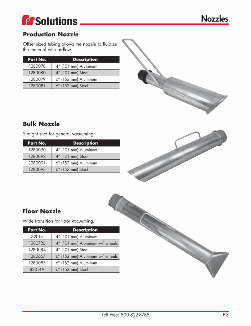
Floor NozzleWide transition for floor vacuuming.
Part No. Description82014 4" (101 mm) Aluminum
1280726 4” (101 mm) Aluminum w/ wheels1280084 4" (101 mm) Steel1280667 6” (152 mm) Aluminum w/ wheels1280083 6" (152 mm) Aluminum82014A 6" (152 mm) Steel
Bulk NozzleStraight shot for general vacuuming.
Part No. Description1280090 4" (101 mm) Aluminum1280092 4" (101 mm) Steel1280091 6" (152 mm) Aluminum1280093 6" (152 mm) Steel
Production NozzleOffset sized tubing allows the nozzle to fluidize the material with airflow.
Part No. Description1280078 4" (101 mm) Aluminum1280080 4" (101 mm) Steel1280079 6" (152 mm) Aluminum1280081 6" (152 mm) Steel

Gaskets
G-1Toll Free: 800-822-8785
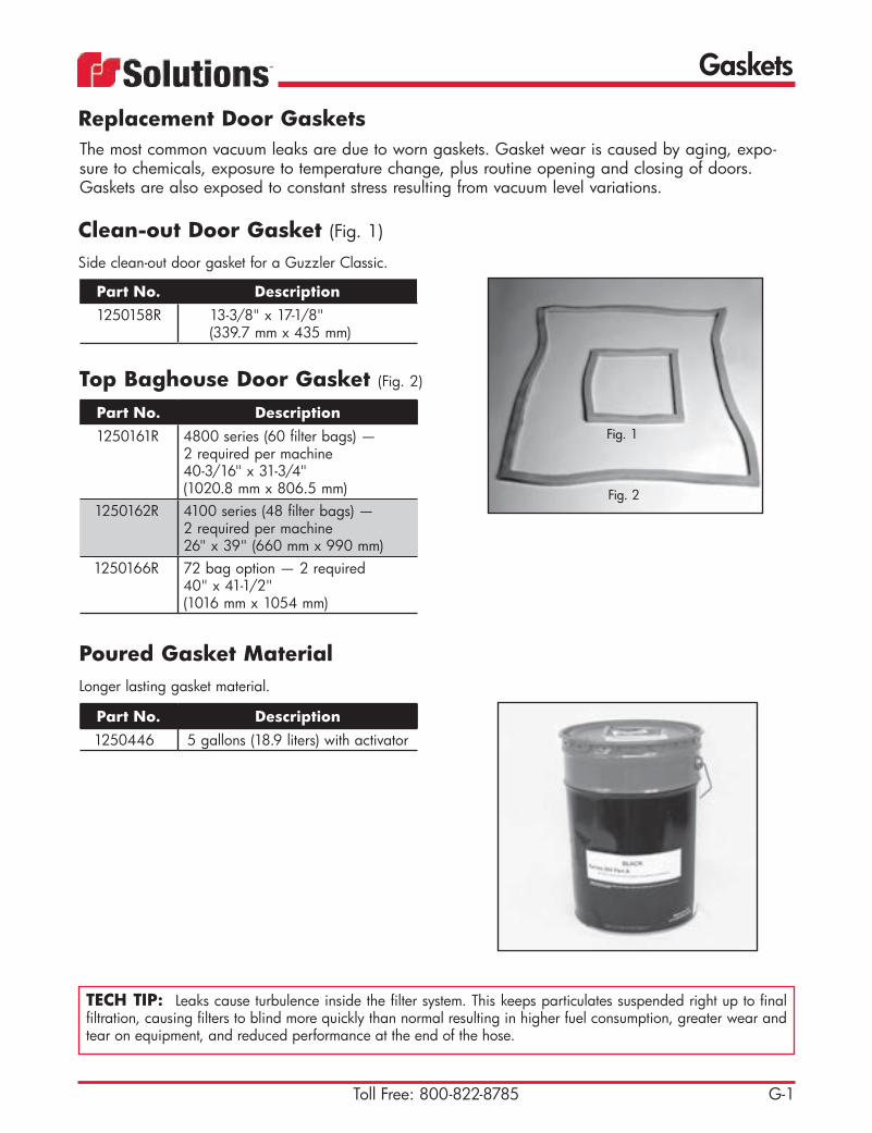
Clean-out Door Gasket (Fig. 1)
Side clean-out door gasket for a Guzzler Classic.
Part No. Description1250158R 13-3/8" x 17-1/8"
(339.7 mm x 435 mm)
Part No. Description1250161R 4800 series (60 filter bags) —
2 required per machine40-3/16" x 31-3/4"(1020.8 mm x 806.5 mm)
1250162R 4100 series (48 filter bags) — 2 required per machine26" x 39" (660 mm x 990 mm)
1250166R 72 bag option — 2 required 40" x 41-1/2" (1016 mm x 1054 mm)
Top Baghouse Door Gasket (Fig. 2)
Fig. 2
Fig. 1
Part No. Description1250446 5 gallons (18.9 liters) with activator
Poured Gasket MaterialLonger lasting gasket material.
The most common vacuum leaks are due to worn gaskets. Gasket wear is caused by aging, expo-sure to chemicals, exposure to temperature change, plus routine opening and closing of doors. Gaskets are also exposed to constant stress resulting from vacuum level variations.
TECH TIP: Leaks cause turbulence inside the filter system. This keeps particulates suspended right up to final filtration, causing filters to blind more quickly than normal resulting in higher fuel consumption, greater wear and tear on equipment, and reduced performance at the end of the hose.
Replacement Door Gaskets
Gaskets
G-2 E-mail: [email protected]
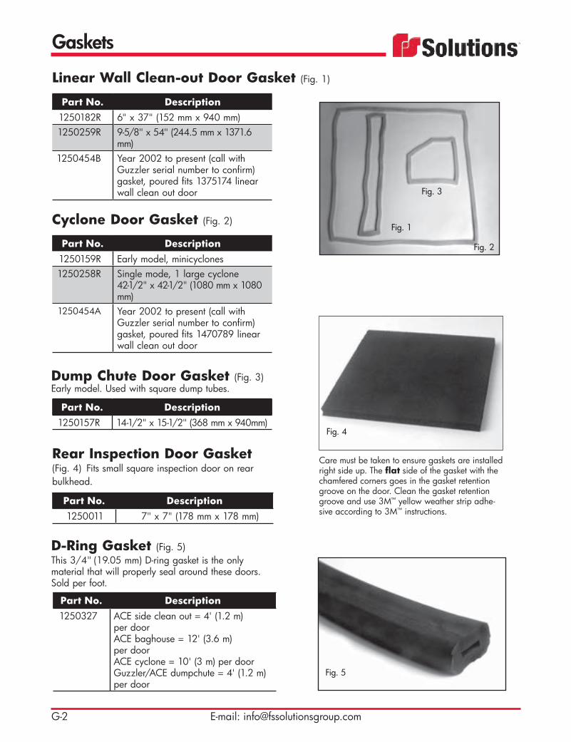
Part No. Description1250182R 6" x 37" (152 mm x 940 mm)1250259R 9-5/8" x 54" (244.5 mm x 1371.6
mm)1250454B Year 2002 to present (call with
Guzzler serial number to confirm) gasket, poured fits 1375174 linear wall clean out door
Linear Wall Clean-out Door Gasket (Fig. 1)
Part No. Description1250159R Early model, minicyclones1250258R Single mode, 1 large cyclone
42-1/2" x 42-1/2" (1080 mm x 1080 mm)
1250454A Year 2002 to present (call with Guzzler serial number to confirm) gasket, poured fits 1470789 linear wall clean out door
Cyclone Door Gasket (Fig. 2)
Part No. Description1250157R 14-1/2" x 15-1/2" (368 mm x 940mm)
Dump Chute Door Gasket (Fig. 3) Early model. Used with square dump tubes.
Fig. 3
Fig. 1
Fig. 2
D-Ring Gasket (Fig. 5) This 3/4" (19.05 mm) D-ring gasket is the only material that will properly seal around these doors. Sold per foot.
Part No. Description1250327 ACE side clean out = 4' (1.2 m)
per doorACE baghouse = 12' (3.6 m) per doorACE cyclone = 10' (3 m) per doorGuzzler/ACE dumpchute = 4' (1.2 m) per door
Rear Inspection Door Gasket (Fig. 4) Fits small square inspection door on rear bulkhead.
Part No. Description1250011 7" x 7" (178 mm x 178 mm)
Care must be taken to ensure gaskets are installed right side up. The flat side of the gasket with the chamfered corners goes in the gasket retention groove on the door. Clean the gasket retention groove and use 3M™ yellow weather strip adhe-sive according to 3M™ instructions.
Fig. 4
Fig. 5

Gaskets
G-3Toll Free: 800-822-8785
Part No. Description1250358 23' L x 2-1/2" W x 1-7/16" D
(7 m x 63.5 mm x 36.5 mm)1250243V 21' L x 2-1/2" W x 1-7/16" D
1250421 Ibex Tailgate Rear Door Seal kit - 20' L x 1.76" W x 72"D.
Full-Opening Tailgate GasketFor ACE and NX units with full open tailgate and Safevac.
Part No. Description1250082 20' 6" L x 1-1/4" W x 1-3/4" D
(6.2 m x 31.7 mm x 44.4 mm)1250345 O-ring35594 Door seal, 255" long
Half-Opening Tailgate Gasket
TECH TIP: Many replacement gaskets shown in this section are direct replacements to the poured-in gaskets. Removal of poured-in gasket material can be difficult. For best results, first score an outer edge with a util-ity knife. Apply mild heat from a heat gun and pull up one edge, working a putty knife or flat chisel under material as you heat. Try to remove the entire gasket in one piece.
All replacement gaskets should be cleaned with an oil-free solvent to thoroughly remove the manufacturer’s mold-release agent. FS Solutions suggest using a Cyanoacrylate rubber adhesive for gasket installation.
Part No. Description1250192 8" (1/2" x 9" ID x 12" OD)
(203 mm; 12.7 mm x 228 mm ID x 305 mm OD)
1250176 10" (1/2" x 10.5" ID x 16" OD)(254 mm; 12.7 mm x 266.7 mm ID x 406 mm OD)
1250012 12" (1/2" x 15" ID x 19" OD)(305 mm; 12.7 mm x 381 mm ID x 482 mm OD)
Expansion Joint Gasket
Part No. Description1250082 255" L
Door Seal
Gaskets
G-4 E-mail: [email protected]
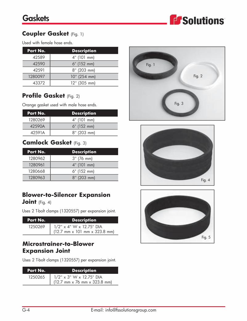
Blower-to-Silencer Expansion Joint (Fig. 4)
Uses 2 T-bolt clamps (1320557) per expansion joint.
Part No. Description1250269 1/2" x 4" W x 12.75" DIA
(12.7 mm x 101 mm x 323.8 mm)
Microstrainer-to-Blower Expansion JointUses 2 T-bolt clamps (1320557) per expansion joint.
Part No. Description1250265 1/2" x 3" W x 12.75" DIA
(12.7 mm x 76 mm x 323.8 mm)
Part No. Description1280962 3" (76 mm)1280961 4" (101 mm)1280668 6" (152 mm)1280963 8" (203 mm)
Camlock Gasket (Fig. 3)
Coupler Gasket (Fig. 1)
Used with female hose ends.
Part No. Description42589 4" (101 mm)42590 6" (152 mm)42591 8" (203 mm)
1280097 10" (254 mm)43372 12" (305 mm)
Profile Gasket (Fig. 2)
Orange gasket used with male hose ends.
Part No. Description1280269 4" (101 mm)42590A 6" (152 mm)42591A 8" (203 mm)
Fig. 2
Fig. 1
Fig. 3
Fig. 4
Fig. 5

Gaskets
G-5Toll Free: 800-822-8785
Flange GasketFor 4" Sluloge 1250236
Part No. Description1250018 4" (1/8" x 4-1/4" ID x 9" OD)
(101 mm; 3.2 mm x 108 mm ID x 228 mm OD)
1250019 6" (1/8" x 6-5/8" ID x 11" OD)(152 mm; 3.2 mm x 168.3 mm ID x 279 mm OD)
1250020 8" (1/8" x 8" ID x 13-1/2" OD)(203 mm; 3.2 mm x 203 mm ID x 343 mm OD)
1250021 10" (1/8" x 10" ID x 16" OD)(254 mm; 3.2 mm x 254 mm ID x 406 mm OD)
1250222 190 D x 12 ID, W/H
Boom Blind Flange Gasket (Fig. 1)
Part No. Description1250025 1/8" x 16-3/8" ID x 20-3/8" OD
(3.2 mm x 415.9 mm x 517.5 mm)1250026 1/8" x 12" ID x 16-1/2" OD
Blower Gasket (Fig. 2)
Part No. Description1250015 14" ID x 21" OD (356 mm x 533
mm) red rubber — inlet side1250016 12" ID x 19" OD (305 mm x 483
mm) red rubber — discharge side1250417 Blower to Inlet Flange
Rubber “U” Strap (Fig. 3)
Used with hydraulic tank straps.
Part No. Description45738A 3" W x 32" L (76 mm x 813 mm)
Float Ball Shut-Off Rubber Seat (Fig. 4) Used on ACE units — 2 required for DF ACE.
Part No. Description1250413 .5" x 8.62" ID x 9.62" OD x
1.5" W (12.7 mm x 218.9 mm x 244.3 mm x 38.1 mm)
Fig. 3
Fig. 4
Fig. 2
Fig. 1

Gaskets
G-6 E-mail: [email protected]
Blower Expansion Joint Hose (Fig. 3) Used on NX units.
Part No. Description1250269A 1/2" x 8" x 12-3/4" ID
(12.7 mm x 203 mm x 323.8 mm)
Make/Break Seal (Fig. 4)
Used on NX units.
Part No. Description1250450D Urethane, 40DURO,
1-3/4" (44.4 mm) thick, red1250362 Gasket, Manifold
.06" x 19.75" 21.25"1230700A Gasket, Blower to Manifold
Gasket for VRB System (Fig. 2)
Used on NX High Dump units.
Part No. Description11221061 8" OD x 1.5" W (203 mm x 38.1
mm), Neoprene seal
1250269 Boot, Blower to silencer1250265 Boot, Microstrainer to blower
Slip Ring for Silencer (Fig. 1)
Part No. Description11220500 3/8" x 12-3/4" ID x 19" OD
(9.5 mm x 324 mm x 482 mm)
Inspection Port GasketPart No. Description
39893 1/8" x 10-1/2" DIA(3.2 mm x 266.7 mm)
Fig. 1
Fig. 2
Fig. 3
Fig. 4
Electrical
H-1Toll Free: 800-822-8785
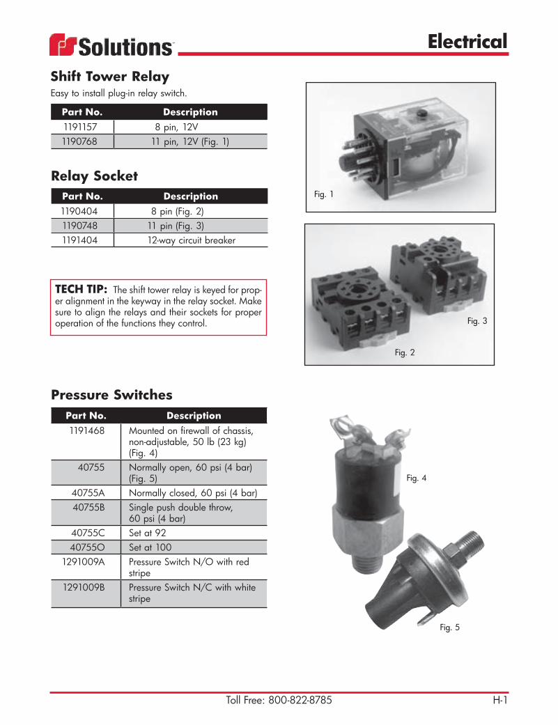
Part No. Description1191157 8 pin, 12V1190768 11 pin, 12V (Fig. 1)
Shift Tower RelayEasy to install plug-in relay switch.
Part No. Description1191468 Mounted on firewall of chassis,
non-adjustable, 50 lb (23 kg) (Fig. 4)
40755 Normally open, 60 psi (4 bar) (Fig. 5)
40755A Normally closed, 60 psi (4 bar)40755B Single push double throw,
60 psi (4 bar)40755C Set at 9240755O Set at 100
1291009A Pressure Switch N/O with red stripe
1291009B Pressure Switch N/C with whitestripe
Pressure Switches
Part No. Description1190404 8 pin (Fig. 2)1190748 11 pin (Fig. 3)1191404 12-way circuit breaker
Relay Socket
Fig. 3
Fig. 2
Fig. 5
Fig. 1
TECH TIP: The shift tower relay is keyed for prop-er alignment in the keyway in the relay socket. Make sure to align the relays and their sockets for proper operation of the functions they control.
Fig. 4

Electrical
H-2 E-mail: [email protected]
Part No. Description46938J Radio Control Unit HXX
46938JB Transmitter for 46938J46938JC Receiver for 46938J46938JA Case for 46938J
46938L Shoulder strap for 46938J46938JF Plastic carry bag for 46938J
46938XAE Belly Pack
Radio Control Unit
Radio control unit can be used to wirelessly control boom, vacuum relief, throttle, recirculation system and water pump on HXX, NX and Guzzler units. Functions are determined by individual order and will vary by model.
Part No. Description Guzzler HXX46938VD Pendant Cap/Chain - Closure Cap/Chain X46938VC Pendant Connector - 5P Female Recept X46938VG Heavy Pendant Cable - 33 Ft X46938VH High-Visibility Shoulder Harness X46938VJ Waist Harness X46938VK Can Receiver X46938VS T110 Leather Pouch w/ Clip X X46938VT T110 Yellow Strap Kit X X46938X Wireless Transmitter/Receiver - T110 X
46938XA Wireless Transmitter/Receiver - T300 X46938XAA 1-Axis Paddle for T300 X46938XAB 2-Axis Joystick for T300 X46938XAC E-Stop Button for T300 X46938XB Wireless Transmitter - T110 X46938XC Wireless Transmitter/Receiver - T110 X46938XD Wireless Transmitter/Receiver - T110 X X46938XE Yellow Button Cover - T110 X X46938XF Wireless Transmitter - Part for 46938X X
46938XCA Wireless Transmitter - Part for 46938XC X46938XG Charging Dock - T110 X X46938XH Rechargeable Batteries - AA NI-CAD X X46938XJ Battery Cover – Yellow w/ Magnets X X
OMNEX Wireless Control Units

Electrical
H-3Toll Free: 800-822-8785
Part No. Description1191490 Rocker switch — increase/
decrease throttle (Fig. 1)1191431 Momentary switch for vibrator
(Fig. 2)1191449 Rocker switch — on/off switch
(Fig. 3)1191450 Rocker switch — on/off throttle
(Fig. 4)1191767 Rocker only1191671 Switch, 2 pos. maintained -
red light one side/green light
Control Panel Switch (Early Model)
Part No. Description1350511 Air-operated with twist lock (Fig.
5)1351115 Air-operated with 4-pin
trailer connection
Vacuum Relief Pendant (Early Model)
Fig. 1
Fig. 2 Fig. 3
Fig. 4
Fig. 5
Part No. Description1351262 Assembly with 8-pin trailer
connection (Fig. 6)
Vacuum Relief Pendant
Fig. 6

Electrical
H-4 E-mail: [email protected]
Part No. Description1350598 Up/down, left/right, brake1350790 Up/down, brake1350741 For XCR unit (Fig. 2)1351263 4-button: up/down, left/right,
open/close (Fig. 3)1351264 6-button: up/down, left/right
(Fig. 4)1351265 8-button: for swing out cyclone
(Fig. 5)1350053 2-button: up/down, with 4-pin
trailer connection (Fig. 6)1350053A 2-button: up/down, with
twist lock
Boom Pendants
Fig. 2
Fig. 4
Fig. 3
Fig. 6
Fig. 5

Electrical
H-5Toll Free: 800-822-8785
Part No. Description1000465J Complete control panel with gaug-
es and switches (wire harness 191362B required when updating)
1190091 3/8" (9.5 mm) copper solder lug for new style control panel
1191027 Circuit breaker for electric vibrator — 60 amp
1200176A 1/8" (3.2 mm) NPT hydraulic cross1353009 New style Guzzler control panel
box only. No gauges or hardware included.
191364 Guzzler wiring harness with 40-pin connection
20358 12V red warning light20358A Yellow indicator light
20359 12V green warning light (qty. 3)40241A Toggle switch (on/off)40755 Pressure switch — 60 psi (4 bar)
42612B Panel light42645E 2-1/2" (63.5 mm) vacuum gauge
with glycerin44592 Fuse panel
44596A 5 amp circuit breaker (qty. 4 )44597 Ground bus44622 Momentary toggle switch45554 Toggle switch
45554A Toggle switch (Fig. 1) 46344L Time delay relay46492 Relay — 75 amp46811T Blower temperature gauge with
switch46811U Air pressure gauge with switch46811V Air pressure sender46846 Hydraulic pressure gauge —
5000 psi (345 bar)47658A Hydraulic adapter used with pres-
sure gauge 4684670140C New style tachometer, tach
sensor 46159B71261 Relay — 12V 30 amp
Control Panel Assembly (New Style)
Fig. 1
Related ItemsSee Page M-14 for replacement Control Panel Butterfly Latches.
Electrical
H-6 E-mail: [email protected]
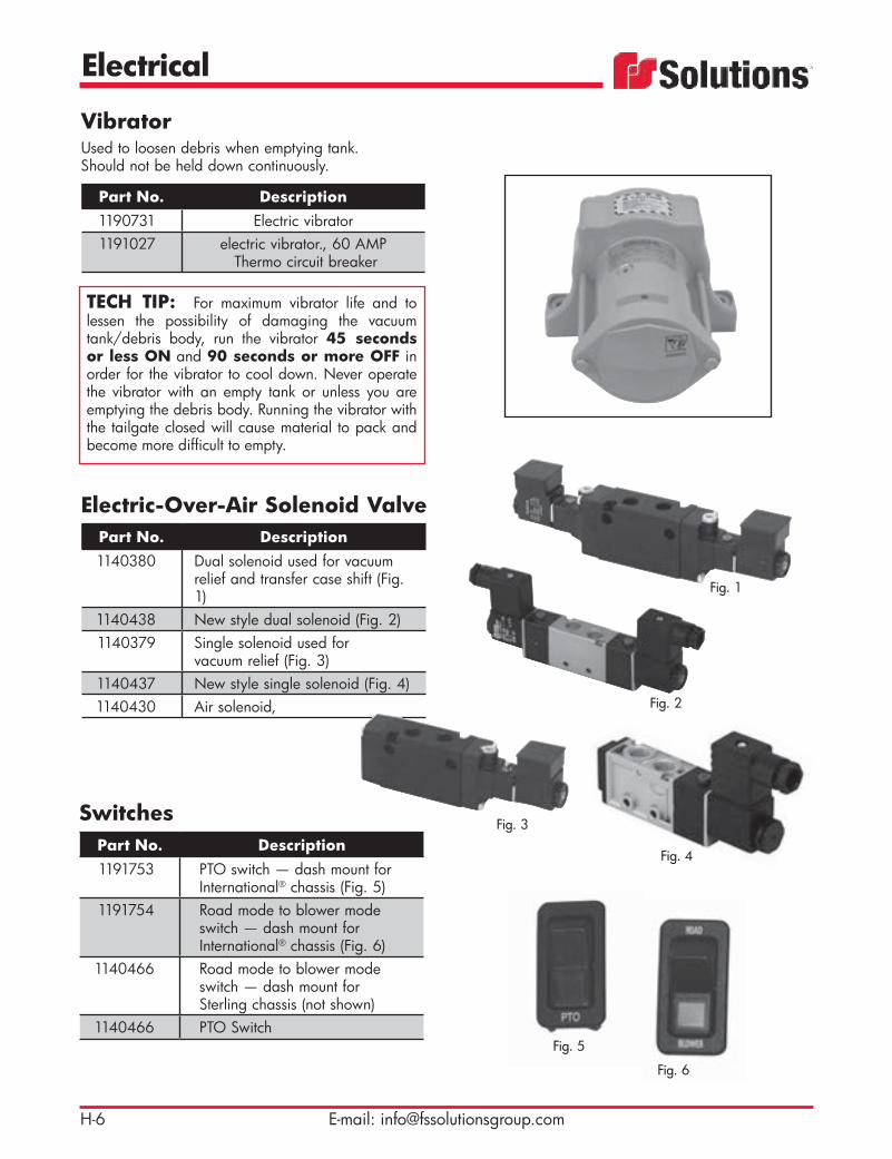
Part No. Description1140380 Dual solenoid used for vacuum
relief and transfer case shift (Fig. 1)
1140438 New style dual solenoid (Fig. 2)1140379 Single solenoid used for
vacuum relief (Fig. 3)1140437 New style single solenoid (Fig. 4)1140430 Air solenoid,
Electric-Over-Air Solenoid Valve
Fig. 1
Fig. 2
Fig. 3
Fig. 4Part No. Description1191753 PTO switch — dash mount for
International® chassis (Fig. 5) 1191754 Road mode to blower mode
switch — dash mount for International® chassis (Fig. 6)
1140466 Road mode to blower mode switch — dash mount for Sterling chassis (not shown)
1140466 PTO Switch
Switches
Fig. 5
Fig. 6
Part No. Description1190731 Electric vibrator 1191027 electric vibrator., 60 AMP
Thermo circuit breaker
VibratorUsed to loosen debris when emptying tank. Should not be held down continuously.
TECH TIP: For maximum vibrator life and to lessen the possibility of damaging the vacuum tank/debris body, run the vibrator 45 seconds or less ON and 90 seconds or more OFF in order for the vibrator to cool down. Never operate the vibrator with an empty tank or unless you are emptying the debris body. Running the vibrator with the tailgate closed will cause material to pack and become more difficult to empty.

Electrical
H-7Toll Free: 800-822-8785
Part No. Description1240428 157" (3988 mm) cable (Fig. 1)1240615 240" (6096 mm) cable1240035 195" (4953 mm) cable1240639 Throttle rod end, 1" (25 mm) stroke1240640 Throttle rod end, 2" (51 mm) stroke1240643 Throttle rod end, 3" (76 mm) stroke
(Fig. 2)1240076 Throttle cable head (Fig. 3)
42654 168" (4267 mm) cable42655 192" (4877 mm) cable
1140024 Air cylinder, 1-1/16”, PH, throttle1240559 throttle linear actuator
46125 Cord reel, steel, 15’
Throttle Cable
Part No. Description42645G Used on NX recovery system
Vacuum Switch
Part No. Description20358D L.E.D., red, 12V (Fig. 4)20358H L.E.D., green, 12V
70499 Clear auxiliary light (Fig. 5)45741 Left-hand tail light — used on
Guzzler units (Fig. 6)45742 Right-hand tail light — used on
Guzzler units45743 Clearance light, Red45744 Clearance light, Amber
1191363 Guzzler/ACE complete light kit36460 Hand spot light with cord
Lights
Fig. 5
Fig. 4
Fig. 1Fig. 2
Fig. 3
When making electrical connections always use high qual-ity connectors and make good quality crimps. Heat shrink tubing is recommended for a secure connection.
Related ItemsSee Page M-14 for Light Brackets.
Fig. 6

Electrical
H-8 E-mail: [email protected]
Part No. Description46159 Old style used with tachometer
1191161 (Fig. 1)46159B New style used with tachometer
70140C (Fig. 2)1191162 Magnetic sensor used with tachom-
eter 1191173 (Fig. 1)49630 Magnetic pickup sensor
1210795 Tach sprocket for blower
Tach Sensor
Part No. Description46492 75 amp power relay for various
control panels (Fig. 3)1190447 12V for vibrator1191109 12V time delay relay (Fig. 4)
6344L Time delay6344F Time delay starter
Relay
Part No. Description44596 10 amp
44596A 5 amp44596C 20 amp
Circuit Breaker
Fig. 4Fig. 3
Part No. Description44129 Pressure protection valve
Pressure Protection ValveRequired when chassis compressed air is used for unit operation. The valve is designed to prevent the accidental release of air pressure and will shut off air to the Guzzler System if air pressure falls to 65 psi (5 bar).
Fig. 1 Fig. 2
Related ItemsSee Page J-2 for Tachometers.

Electrical
H-9Toll Free: 800-822-8785
Part No. Description47772 Electric throttle switch used on NX
vacuum recovery system40241 Switch - toggle SPST Off/On
1190357 Contact Block, special early closing
1190334 Switch, 3-position Select, w/ manual return
3-Position Throttle Switch
Part No. Description47903AA Sender boot
Temperature Sending Unit Boot
Part No. Description47903A 300ºF (149ºC)
Blower Temperature Sending Unit
Part No. Description46811V 200 psi (14 bar)
Air Pressure Sender

Electrical
H-10 E-mail: [email protected]
Part No. Description1140456 Air Solenoid Valve Assembly (Fig 1)
1140456A Replacement Solenoid (Fig. 2)
1140456B Replacement Valve Module (Fig. 3)
Air Solenoid Assembly
Part No. Description1191717 12V — used as main power relay
in various control panels
Solenoid (Fig. 4)
Part No. Description1140430 For International® chassis 2674
Air Solenoid (Fig. 5)
Part No. Description1353001 Upgrade kit for Dana transfer case
(See drawing)
Replacement Solenoid Kit
Fig. 3
Fig. 1
Fig. 2
Fig. 4
Fig. 5
Electrical
H-11Toll Free: 800-822-8785
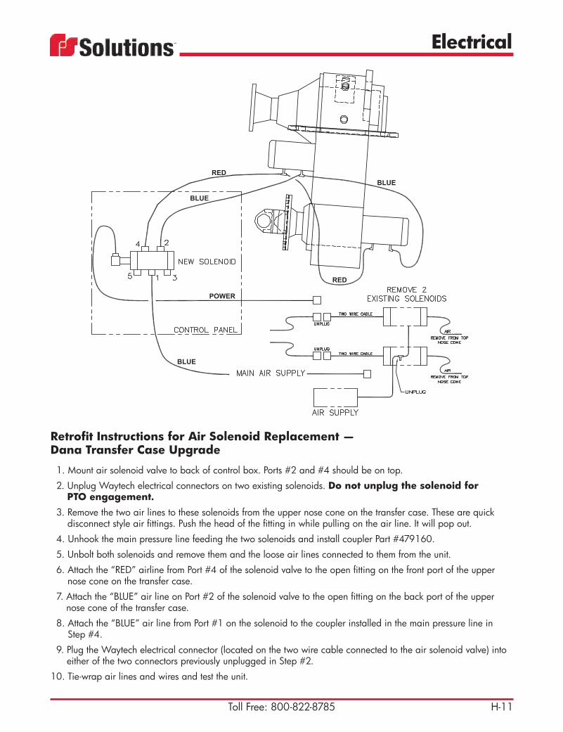
Retrofit Instructions for Air Solenoid Replacement — Dana Transfer Case Upgrade
1. Mount air solenoid valve to back of control box. Ports #2 and #4 should be on top.
2. Unplug Waytech electrical connectors on two existing solenoids. Do not unplug the solenoid for PTO engagement.
3. Remove the two air lines to these solenoids from the upper nose cone on the transfer case. These are quick disconnect style air fittings. Push the head of the fitting in while pulling on the air line. It will pop out.
4. Unhook the main pressure line feeding the two solenoids and install coupler Part #479160.
5. Unbolt both solenoids and remove them and the loose air lines connected to them from the unit.
6. Attach the “RED” airline from Port #4 of the solenoid valve to the open fitting on the front port of the upper nose cone on the transfer case.
7. Attach the “BLUE” air line on Port #2 of the solenoid valve to the open fitting on the back port of the upper nose cone of the transfer case.
8. Attach the “BLUE” air line from Port #1 on the solenoid to the coupler installed in the main pressure line in Step #4.
9. Plug the Waytech electrical connector (located on the two wire cable connected to the air solenoid valve) into either of the two connectors previously unplugged in Step #2.
10. Tie-wrap air lines and wires and test the unit.

Electrical
H-12 E-mail: [email protected]
Part No. Description1191689 Push/Pull-On/Off switch used
in electrical circuits of many Guzzler products
Push-Pull Maintained Switch
Part No. Description191362A Early Model191362B New Style — works with con-
trol panel shown on page H-4
Wiring HarnessMain wiring harness for Guzzler Classic/ACE.
Part No. Description191138 Dual axis joystick used on High Rail
boom (Fig. 1)1191291 Microswitch for 191138 joystick1191658 Forward/Reverse joystick used on
High Rail creep drive system (Fig. 2)
1191073 Panel box used for dual axis joy-stick, 6" x 6" x 4" NEMA (152 mm x 152 mm x 101 mm)
1191353 Proportional joystick used on early model High Rail units with PTO driven hydraulic pump
Joystick
Fig. 2
Fig. 1
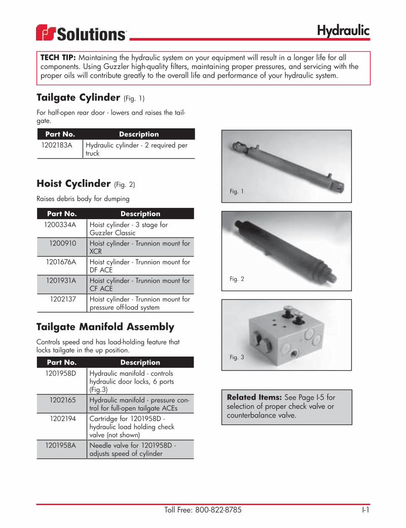
Hydraulic
I-1Toll Free: 800-822-8785
Part No. Description1202183A Hydraulic cylinder - 2 required per
truck
Tailgate Cylinder (Fig. 1)
For half-open rear door - lowers and raises the tail-gate.
Part No. Description1200334A Hoist cylinder - 3 stage for
Guzzler Classic1200910 Hoist cylinder - Trunnion mount for
XCR1201676A Hoist cylinder - Trunnion mount for
DF ACE1201931A Hoist cylinder - Trunnion mount for
CF ACE1202137 Hoist cylinder - Trunnion mount for
pressure off-load system
Hoist Cyclinder (Fig. 2)
Raises debris body for dumping
Part No. Description1201958D Hydraulic manifold - controls
hydraulic door locks, 6 ports (Fig.3)
1202165 Hydraulic manifold - pressure con-trol for full-open tailgate ACEs
1202194 Cartridge for 1201958D - hydraulic load holding check valve (not shown)
1201958A Needle valve for 1201958D - adjusts speed of cylinder
Tailgate Manifold Assembly Controls speed and has load-holding feature that locks tailgate in the up position.
TECH TIP: Maintaining the hydraulic system on your equipment will result in a longer life for all components. Using Guzzler high-quality filters, maintaining proper pressures, and servicing with the proper oils will contribute greatly to the overall life and performance of your hydraulic system.
Fig. 1
Fig. 2
Fig. 3
Related Items: See Page I-5 for selection of proper check valve or counterbalance valve.
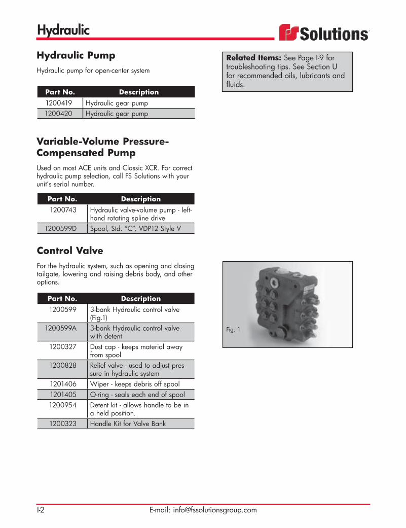
Hydraulic
E-mail: [email protected]
Part No. Description1200419 Hydraulic gear pump1200420 Hydraulic gear pump
Hydraulic PumpHydraulic pump for open-center system
Part No. Description1200743 Hydraulic valve-volume pump - left-
hand rotating spline drive1200599D Spool, Std. “C”, VDP12 Style V
Variable-Volume Pressure-Compensated PumpUsed on most ACE units and Classic XCR. For correct hydraulic pump selection, call FS Solutions with your unit’s serial number.
Part No. Description1200599 3-bank Hydraulic control valve
(Fig.1)1200599A 3-bank Hydraulic control valve
with detent1200327 Dust cap - keeps material away
from spool1200828 Relief valve - used to adjust pres-
sure in hydraulic system1201406 Wiper - keeps debris off spool1201405 O-ring - seals each end of spool1200954 Detent kit - allows handle to be in
a held position.1200323 Handle Kit for Valve Bank
Control Valve For the hydraulic system, such as opening and closing tailgate, lowering and raising debris body, and other options.
Related Items: See Page I-9 for troubleshooting tips. See Section U for recommended oils, lubricants and fluids.
Fig. 1
Hydraulic
I-3Toll Free: 800-822-8785
Part No. Description1202215 Cylinder - opens and closes Dezurik
valve1201175A Repair kit used for 1201175 - allows
cylinder to be rebuilt and reused1201816 Piston - fits 12011751201186 Rod clevis - allows cylinder to be
connected to any option1202199 Cylinder1202208 Cylinder - for rear NX door
Hydraulic Cylinders
Part No. Description70294 10 micron
Filter Breather Assembly
TECH TIP: As with any oil filter instal-lation, coat the seal on the new filter prior to installing it.
Part No. Description1200303 Suction filter1202167 Spin-on 25 micron filter element
1200303A Suction filter, old style1200304 Suction filter element1201309 Return filter assembly1201310 10 micron filter element
46864 2” (51 mm) NPT suction strainer (Fig. 3)
48209A Filter element for 48208A42431A Filter element for 48208A42431B 10 micron filter element for
62643M42431 10 micron filter element for 6264342429 Oil filter assembly (SAE#20/10MIC)
Hydraulic Filters
Part No. Description1375213 50 gallon (189.3 liters) round style
Hydraulic Tank

Hydraulic
E-mail: [email protected]
Part No. Description89423 For full-opening tailgate system
89423H Bolt for hydraulic lock assembly89423N Nut for Hydraulic lock assembly
Hydraulic Lock Assembly
Part No. Description47986 Hydraulic shuttle valve
Shuttle Valve
Part No. Description1336149 Tailgate over-center lock
Tailgate Lock
Part No. Description1201400 Check valve used to keep cyclone
discharge valve seated when closed
1200350 Selector valve for Guzzler equip-ment
46644 Selector valve for Vactor equipment1200348 Flow divider valve
Sandwich Valve
Part No. Description1202080 Hydraulic boom motor w/ brake1200464 Motor, Hydraulic rotating boom
Boom Motor
Part No. Description
45136C Telescoping boom – Extendable cylinder
48440E Telescoping boom – Lift cylinder1202207 Fixed boom – Lift cylinder
Boom Cylinder
Fig. 1
Fig. 2
Hydraulic
I-5Toll Free: 800-822-8785
Part No. Description1200344 Sub plate1200346 Sub plate - dual1200951 Sub plate - 2 station parallel1202008 Sub plate - 3 station parallel
Subplate for Solenoid Valves
Part No. Description1201570 Valve 6 port - used for boom func-
tions and on ACE and Guzzler tail-gates
1202206 Dual valve - used for hoist cylinder with a power up or down
Hoist Cylinder Controls
Part No. Description1200341 12V1201771 Block center used in conjunction
with variable volume pump1201780 12V, open-center used in conjunc-
tion with open-center system hydraulic pump
1201994 Directional valve, A-B tank45302H Valve Hyd. Directional, solenoid
45302EA Valve, Sect, 2nd or 3rd 45302E45302IA Valve, Sect, 1st on 45302I45302D Valve, Std. Directional, Solenoid45302B Coil, 12V, Dual Wires, for BV061191011 Connector, Din Standard
Solenoid Valve
Related Items: See Page I-9 for troubleshooting tips.

Hydraulic
E-mail: [email protected]
Part No. Description1200353 Hydraulic vibrator1200592 Motor, global hyd. vibrator
Vibrator Used to loosen debris when emptying the tank. Should not be held down continuously.
TECH TIP: For maximum vibrator life and to lessen the possibility of damaging the vacuum tank/debris body, run the vibrator 45 seconds or less ON and 90 seconds or more OFF in order for the vibrator to cool down. Never operate the vibrator with an empty tank or unless you are emptying the debris body. Running the vibrator with the tailgate closed will cause material to pack and become more difficult to empty.
Related Items: See Page I-9 and I-10 for troubleshooting tips.
Hydraulic
I-7Toll Free: 800-822-8785
Recommended Practices for Handling and Storage of Hydraulic ComponentsThe life of the hydraulic system is directly related to cleanliness. Typically, the cleaner a system is, the longer it will last. Particle or chemical contamination. Therefore is the enemy of any hydraulic system and extra effort should be taken to avoid contamination whenever and where ever possible. The following is a list of good practices to reduce or eliminate potential contamination while storing, handling, assem-bling and using hydraulic system components.
Ports & Fittings• Port plugs should remain in components and hoses until ready to use.• Use care in removing port plugs so that plastic does not shear off in the threads• Use caution to ensure excess paint near the port face does not chip or fall off the unit.• The area around the port face is a sealing surface and should be protected from dents or contami-
nation• Fittings being screwed into the port should be clean and lubricated.
Assembly & Storage• Hose and tube assemblies should be flushed and capped until used.• Reservoirs should be pickled treated with rust protection and sealed until used. At the time of use the
rust protection must be flushed out.• Never use shop air to blow out a tube, hose or reservoir as the air supply may not be “clean” air.• Filter caps should be kept clean• Hydraulic assembly areas should be free of airborne contaminants.• If components are stored in a cold environment, be sure to remove any condensation that may occur
as components warm up.• If storage is prolonged, components, may need to be rust proofed.
Fluids• Hydraulic fluid should be filtered to ISO 18/13 or better for initial fill.• Water and hydraulic fluid do not mix; water is considered a foreign chemical contaminant• Any surface in contact with hydraulic fluid must be clean and dry.• Random sampling should be taken from hydraulic system on vehicles ready to ship to ensure cleanli-
ness level meets ISO 18/13 or better.
Exposed Surfaces• Exposed cylinder rods should be handled with care to avoid scratches and dents.• Motor and pump shafts should be kept clean and free of physical damage. Splines should be
coated with anti-seize compound or grease before assembly. Tapered shafts should also be protect-ed from physical damage to shaft and coupling ID.

Hydraulic
E-mail: [email protected]
Recommended Start-up Procedure for New or Rebuilt Pump or MotorBefore installing a new or rebuilt pump or motor, back out the main relief valve until the spring tension on the adjusting screw is relaxed. This will avoid the possibility of immediate damage to the replace-ment unit in the event that the relief valve setting has been increased beyond the recommended operat-ing pressure prior to removing the old unit.Before connecting any lines to the pump or motor, fill all ports with clean oil to provide initial lubrication. This is particularly important when the unit is located above the oil reservoir.After connecting the lines and mounting the replacement unit, operate the pump or motor for at least two minutes at zero pressure at the lowest possible RPMs. During this break-in period, the unit should run free and not develop an excessive amount of heat. If the unit operates properly, the speed and the pres-sure can then be increased to the normal operating settings.Reset the main relief valve to it’s proper setting while the pump is running at maximum operating engine (motor) speed for the vehicle.
ALWAYS USE AN ACCURATE GAUGE WHEN ADJUSTING THE RELIEF VALVE PRESSURE SETTING.

Hydraulic
I-9Toll Free: 800-822-8785
PROBLEM PROBABLE CAUSE REMEDYExcessive pump noise Low oil level in the reservoir
Air in the system
Vacuum condition
Oil too thick
Cold weather
Fill reservoir to the proper level with the recommended transmission fluid. DO NOT over fill or damage may result.
Open reservoir cap and operate hydrau-lic system until purged.
“bleed” hydraulic lines at the highest point downstream of auxiliary pump and while system is under pressure.
Check inlet (suction) line and fittings for leaks.
Check auxiliary pump function.
Be certain correct type of oil is used for refilling or adding to the system.
Run hydraulic system until unit is warm to the touch and noise disappears.
Pump overheating Internal leakage
Heat exchanger not functioning (if so equipped)
Fluid level low
Relief valve and compensator settings
If established that excessive internal leakage is evident, return the vehicle to maintenance shop for evaluation and repair.
Locate trouble and repair or replace.
Add oil to operating level.
Set relief valve and compensator in proper sequence to match schematic
System not developing pressure Relief valve open (if so equipped) Compensator mis-adjusted
Loss of fluid internally (slippage)
Replace one or both. Do not attempt to repair cartridges, they are factory as-sembled and preset.
Return vehicle to maintenance shop for repair of hydraulic system.
Loss of fluid Ruptured hydraulic lines
Loose fittings
Leaking gaskets or seals in pump of circuit
Check all external connections, tubing and hoses. Tighten connections, replace ruptured tube or hose.
Observe mating sections of hydraulic for leaks. Replace seals or gaskets if pos-sible.
Replace seals or gaskets if possible.
Miscellaneous Sheared shaft key
Disconnected or broken drive mechanisms
Locate and repair.

Hydraulic
E-mail: [email protected]
PROBLEM PROBABLE CAUSES REMEDYVibrator will not run Power source not connected to vibrator
Push button or solenoid not functioning
Vibrator not grounded properly (DC only)
Vibrator failure
Check all connections.
Replace component.
Remove vibrator from mount and clean any paint, heavy rust, etc. from mounting surface. Add ground strap from truck box to frame.
If warranty is still in effect, contact factory.
Vibrator noisy Vibrator mounting bolts loose
Broken welds on mounting assembly
Motor brushes (DC only) on bearings worn
Re-torque mounting bolts.
Repair welds.
Repair or replace.Fluid leakage (hydraulic only)
Loose fittings. Replace one or both. Do not attempt to repair cartridges, they are factory assembled and preset.
Return vehicle to maintenance shop for repair of hydraulic system.
Fluid in housing (hydraulic only)
Motor seal failure. Check all connections, and replace if neces-sary.
Excessive back pressure (hydraulic only)
Running equipment on return line.
Return line too small.
Cause drain not used.
Run dedicated return line.
Use 3/4” (19.05 mm) or larger line.
Run 1/2” (12.7 mm) or larger line from tank to case drain.
Pressure spikes (hydraulic only)
Running equipment from pressure line.
Turning on pressure with oil flow set on max.
Running system without a pressure relief valve before vibrator, or instant start when vibrator is cold.
Run dedicated pressure line for vibrator with flow control valve and follow plumbing diagram.
Over-speeding(hydraulic only)
Running system without controlling oil flow to vibrator.
Set max. oil flow to vibrator at or below max. rated G.P.M.
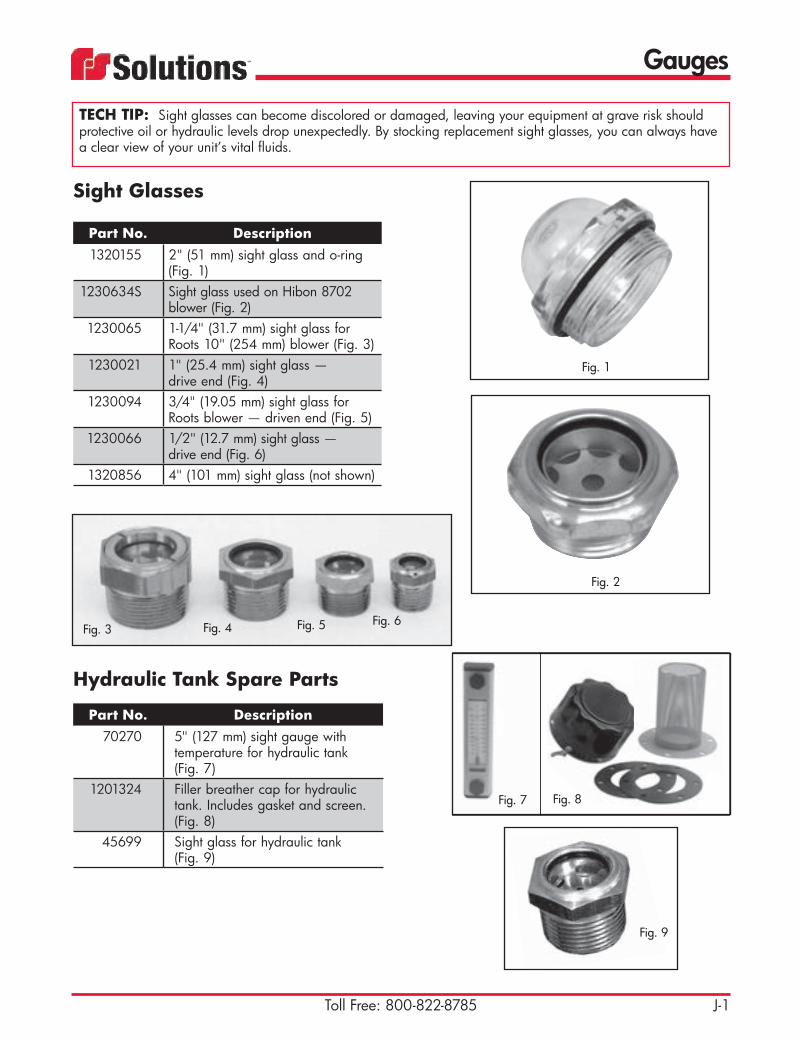
J-1Toll Free: 800-822-8785
Gauges
Part No. Description1320155 2" (51 mm) sight glass and o-ring
(Fig. 1)1230634S Sight glass used on Hibon 8702
blower (Fig. 2)1230065 1-1/4" (31.7 mm) sight glass for
Roots 10" (254 mm) blower (Fig. 3)1230021 1" (25.4 mm) sight glass —
drive end (Fig. 4)1230094 3/4" (19.05 mm) sight glass for
Roots blower — driven end (Fig. 5)1230066 1/2" (12.7 mm) sight glass —
drive end (Fig. 6)1320856 4" (101 mm) sight glass (not shown)
Sight Glasses
Fig. 1
Fig. 3 Fig. 4 Fig. 5 Fig. 6
Fig. 2
Fig. 9
Fig. 7 Fig. 8
TECH TIP: Sight glasses can become discolored or damaged, leaving your equipment at grave risk should protective oil or hydraulic levels drop unexpectedly. By stocking replacement sight glasses, you can always have a clear view of your unit’s vital fluids.
Part No. Description70270 5" (127 mm) sight gauge with
temperature for hydraulic tank (Fig. 7)
1201324 Filler breather cap for hydraulic tank. Includes gasket and screen. (Fig. 8)
45699 Sight glass for hydraulic tank (Fig. 9)
Hydraulic Tank Spare Parts
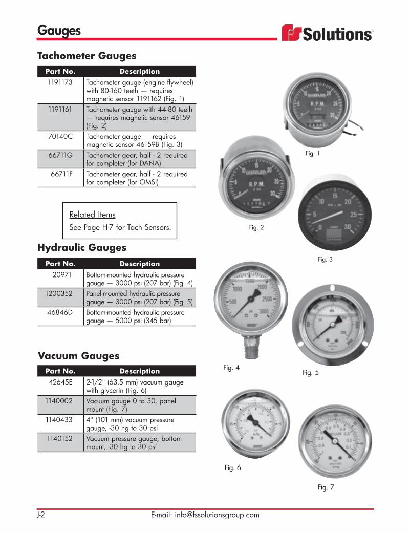
J-2 E-mail: [email protected]
Gauges
Part No. Description1191173 Tachometer gauge (engine flywheel)
with 80-160 teeth — requires magnetic sensor 1191162 (Fig. 1)
1191161 Tachometer gauge with 44-80 teeth — requires magnetic sensor 46159 (Fig. 2)
70140C Tachometer gauge — requires magnetic sensor 46159B (Fig. 3)
66711G Tachometer gear, half - 2 required for completer (for DANA)
66711F Tachometer gear, half - 2 required for completer (for OMSI)
Tachometer Gauges
Part No. Description42645E 2-1/2" (63.5 mm) vacuum gauge
with glycerin (Fig. 6)1140002 Vacuum gauge 0 to 30, panel
mount (Fig. 7)1140433 4" (101 mm) vacuum pressure
gauge, -30 hg to 30 psi1140152 Vacuum pressure gauge, bottom
mount, -30 hg to 30 psi
Vacuum Gauges
Part No. Description20971 Bottom-mounted hydraulic pressure
gauge — 3000 psi (207 bar) (Fig. 4)1200352 Panel-mounted hydraulic pressure
gauge — 3000 psi (207 bar) (Fig. 5)46846D Bottom-mounted hydraulic pressure
gauge — 5000 psi (345 bar)
Hydraulic Gauges
Fig. 7
Fig. 6
Fig. 2
Fig. 3
Fig. 1
Fig. 4Fig. 5
Related ItemsSee Page H-7 for Tach Sensors.

J-3Toll Free: 800-822-8785
Gauges
Part No. Description46568 Temperature gauge — 320ºF
(160ºC) for 15" (381 mm) blower43072 Temperature gauge — 450ºF
(232ºC)1190842 Temperature gauge — 440ºF
(227ºC) for 18" (457 mm) or 27" (686 mm)blower (Fig. 1)
Temperature Gauges
Part No. Description46846 5000 psi (345 bar) pressure gauge
— rear port (Fig. 2)46811U Air pressure gauge with switch
used on NX units (Fig. 3)
Pressure Gauges
Fig. 1
Fig. 2
Fig. 3
TECH TIP: Guzzler temperature gauges have a remote sensing bulb connected to the gauge head by a sealed capillary system. DO NOT CUT THIS CAPILLARY OR BEND AT A SHARP ANGLE. The sensing bulb and capillary are filled with a liquid. When heat is applied to the sensing bulb the liquid turns to a vapor which exerts pressure against the diaphragm movement of the gauge. This movement is read on the dial face as temperature. Temperature gauges are effective preventive maintenance tools. For optimum performance, check these tools pe-riodically: look for frozen pointers, kinked/worn tubing, broken wiring or loose connections. Replace damaged/worn parts; clean/repair as necessary.

J-4 E-mail: [email protected]
Gauges
Part No. Description46811T Blower temperature gauge with
switch used on NX units
Blower Temperature Gauge
Part No. Description1140078 Magnehelic gauge, 0-10"
(0-254 mm) water column (Fig. 1)1140003 Magnehelic gauge, 0-100"
(0-2540 mm) water column (Fig. 2)
Magnehelic Gauges
Fig. 2
Fig. 1
TECH TIP: Guzzler supplied magnehelic gauges require no lubrication or periodic service. Keep case exterior and cover clean. Occasionally disconnect pressure lines to vent both sides of gauge and re-zero. If your magne-helic gauge does however fail to function properly here are some things to look for: 1) Make sure the duplicate pressure port is not plugged. 2) Diaphragm may be ruptured from overpressure. 3) Fittings or sensing lines may be blocked, pinched or leaking. 4) Cover loose or O-ring damaged or missing. 5) Pressure sensor improperly located. 6) Ambient temperature may be below 20ºF (-7ºC).

Valves
K-1Toll Free: 800-822-8785
Brass Lever Gate Valve (Fig. 1)
Part No. Description40019A 3" (76 mm) with handle40019B 4" (101 mm) with handle40019H 6" (152 mm) with handle
Valve Handle (Fig. 2)
Part No. Description40019C Handle for 3" (76 mm) valve40019E Handle for 4" (101 mm) valve40019L Handle for 6" (152 mm) valve
Fig. 2
Fig. 1
Brass Ball ValvePart No. Description1150135 1/4" (6.3 mm) valve1150136 1/2" (12.7 mm) valve1150137 3/4" (19.05 mm) valve1150138 1" (25.4 mm) valve1150689 1-1/4" (31.75 mm) valve47063D 1-1/2" (38.1 mm) valve1150140 2" (51 mm) valve1150238 2-1/2" (63.5 mm) valve1150141 3" (76 mm) valve1150239 4" (101 mm) valve1201605 1-1/4" (31.75 mm) 3-way valve150453 1" (25.4 mm) 3-way valve
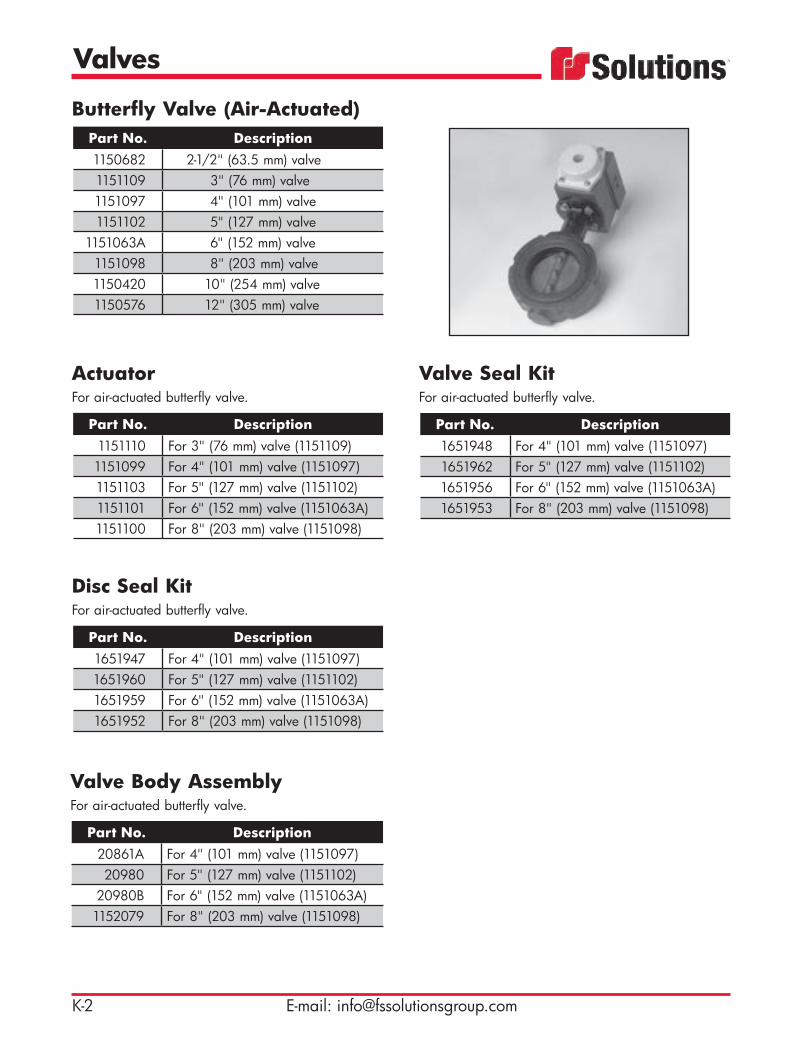
Valves
K-2 E-mail: [email protected]
Butterfly Valve (Air-Actuated)Part No. Description1150682 2-1/2" (63.5 mm) valve1151109 3" (76 mm) valve1151097 4" (101 mm) valve1151102 5" (127 mm) valve
1151063A 6" (152 mm) valve1151098 8" (203 mm) valve1150420 10" (254 mm) valve1150576 12" (305 mm) valve
Disc Seal KitFor air-actuated butterfly valve.
Part No. Description1651947 For 4" (101 mm) valve (1151097)1651960 For 5" (127 mm) valve (1151102)1651959 For 6" (152 mm) valve (1151063A)1651952 For 8" (203 mm) valve (1151098)
ActuatorFor air-actuated butterfly valve.
Part No. Description1151110 For 3" (76 mm) valve (1151109)1151099 For 4" (101 mm) valve (1151097)1151103 For 5" (127 mm) valve (1151102)1151101 For 6" (152 mm) valve (1151063A)1151100 For 8" (203 mm) valve (1151098)
Valve Body AssemblyFor air-actuated butterfly valve.
Part No. Description20861A For 4" (101 mm) valve (1151097)20980 For 5" (127 mm) valve (1151102)
20980B For 6" (152 mm) valve (1151063A)1152079 For 8" (203 mm) valve (1151098)
Valve Seal KitFor air-actuated butterfly valve.
Part No. Description1651948 For 4" (101 mm) valve (1151097)1651962 For 5" (127 mm) valve (1151102)1651956 For 6" (152 mm) valve (1151063A)1651953 For 8" (203 mm) valve (1151098)

Valves
K-3Toll Free: 800-822-8785
Knifegate Valve (Air-Actuated)Part No. Description1150974 4" (101 mm) valve1150571 6" (152 mm) valve1150460 8" (203 mm) valve1150311 10" (254 mm) valve
Knifegate Valve (Manual)Part No. Description1150774 3" (76 mm), hand wheel actuated1150204 4" (101 mm), hand wheel actuated1150145 6" (152 mm), hand wheel actuated1150326 8" (203 mm) valve1150146 10" (254 mm), hand wheel actuated
48257 4” (101 mm) TTMA flangw46347 10” (254 mm), knife valve Dzurik
KNF1150550A 8” (203 mm) Valve seat kit
Knifegate ValveManual carbon steel valve.
Part No. Description1150524 4" (101 mm), flange to flange 1150525 6" (152 mm), flange to flange1150429 4" (101 mm), flange to male
pipe threads 1150430 6" (152 mm), flange to male
pipe threads1150430A 6” (152 mm), TTMA flange
Butterfly Valve (Manual)Part No. Description
1151111 3" (76 mm) valve1151104 Handle for 3" (76 mm) valve20861A 4" (101 mm) valve44676 Handle for 4" (101 mm) valve
(Fig. 1)20980B 6" (152 mm) valve44730B Handle for 6" (152 mm) valve1150134 8" (203 mm) valve1150656 10" (254 mm) valve1150722 12" (305 mm) valve Fig. 1

Valves
K-4 E-mail: [email protected]
Dezurik Valve (Fig. 1)
Part No. Description1150544E 12" (305 mm) valve, KGC series1150544 16" (406 mm) valve, knifegate
Dezurik Valve Blade (Fig. 2)
Part No. Description1150747 12" (305 mm) blade1150529 16" (406 mm) blade
Dezurik Valve Packing (Fig. 3)
Part No. Description1250120 3/4" (19.05 mm) packing for liq-
uid ring pump1250329 1/2" (12.7 mm) Teflon® packing
Dezurik Valve SeatsPart No. Description1150544F For 12" (305 mm) valve, KGC series1150589 Viton® for 12" (305 mm) valve (Fig. 4)1150654 Viton® stainless steel for 12"
(305 mm) valve1150733 Viton® stainless steel for 12"
(305 mm) valve1151081 High-temp for 12" (305 mm) valve1151092 For 12" (305 mm) valve, KGL series
(Fig. 5)1250335 For 12" (305 mm) valve, plastic
.54" x 11.88" OD x 10.63" ID(13.7 mm x 301.7 mm x 270 mm) (Fig. 6)
1250124 O-ring type for 16" (406 mm) valve1250343 For 16" (406 mm) valve, Teflon®
.515" x 15.595" OD x 13.75" ID(13.1 mm x 396.1 mm x 349 mm)
Fig. 1
Fig. 2
Fig. 4
Fig. 5
Fig. 6
Fig. 3

Valves
K-5Toll Free: 800-822-8785
Kunkle ValvePart No. Description
42633 3" (76 mm) vacuum relief valve — preset at 15" Hg (381 mm/Hg) (Fig. 1)
1350982 3" (76 mm) valve preset at 18" (457 mm)
1140263 3" (76 mm) pressure relief valve preset at 14.5 psi (.99 bar)
1140064 2" (51 mm) pressure relief valve (Fig. 2) Fig. 1
Fig. 2
Safety Screen BasketPart No. Description1150147 3" (76 mm) for vacuum relief valve1150148 4" (101 mm) for vacuum relief valve1150547 6" (152 mm) for vacuum relief valve1150247 8" (203 mm) for vacuum relief valve1150850 10" (254 mm) for vacuum relief valve
Directional Control ValvePart No. Description1140265 Pneumatic directional
control valve
Kunkle valves are essential to maintain the proper vacuum rating for your specific blower and protecting against overheating. Pressure relief valves are essential to properly maintain the safe working pressure of your vacuum unit.

Valves
K-6 E-mail: [email protected]
Air Fitting ManifoldPart No. Description1140465 Used on NX units
Air FilterPart No. Description1140458 1/2" (12.7 mm) NPT — used on
NX units
TECH TIP: Proper air filter maintenance is critical for component operation. Condensation during the compres-sion of air and water vapor can cause contaminants in the lines. These particles need to be removed before they reach the pneumatic equipment, such as valves and cylinders. Particles can damage and clog small orifices in the equipment unless they are filtered out. Filters separate the water droplets and particles from the air before they reach your pneumatic equipment.

Valves
K-7Toll Free: 800-822-8785
Air ShifterPart No. Description1140074 With one supply 1 delivery for PTO1140048 With one supply 2 delivery for TC
Air ValveUsed to engage and disengage fluidizing nozzles on NX baghouses.
Part No. Description1140460 2-way air valve

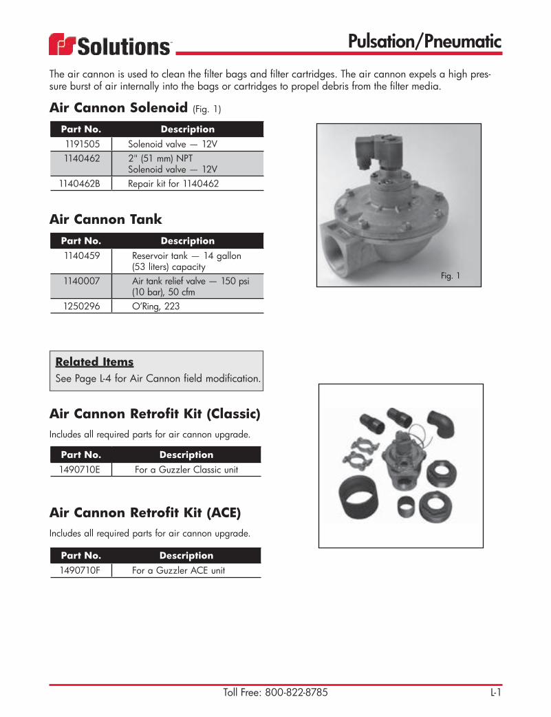
Pulsation/Pneumatic
L-1Toll Free: 800-822-8785
Air Cannon Solenoid (Fig. 1)
Part No. Description1191505 Solenoid valve — 12V1140462 2" (51 mm) NPT
Solenoid valve — 12V1140462B Repair kit for 1140462
Air Cannon TankPart No. Description1140459 Reservoir tank — 14 gallon
(53 liters) capacity1140007 Air tank relief valve — 150 psi
(10 bar), 50 cfm1250296 O’Ring, 223
Air Cannon Retrofit Kit (Classic)Includes all required parts for air cannon upgrade.
Part No. Description1490710E For a Guzzler Classic unit
Air Cannon Retrofit Kit (ACE)Includes all required parts for air cannon upgrade.
Part No. Description1490710F For a Guzzler ACE unit
The air cannon is used to clean the filter bags and filter cartridges. The air cannon expels a high pres-sure burst of air internally into the bags or cartridges to propel debris from the filter media.
Fig. 1
Related ItemsSee Page L-4 for Air Cannon field modification.

Pulsation/Pneumatic
L-2 E-mail: [email protected]
Pressure TransducerHigh/Low pressure switch for pulsation system.
Part No. Description1190017 Pressure transducer1140443 Air Dryer
1651775A Element Kit, Air Dryer Dessicant
RelayControl timer for pulsation system.
Part No. Description1191109 8-pin time-delay relay for
air cannon — 12V1191157 8-pin time-delay relay for
XCR timer — 12V46344L Relay - time delay on make, DIP
SW
Skinner ValveAir supply valve for pulsation system.
Part No. Description1140461 1/2" (12.7 mm) NPT solenoid
valve — 12V

Pulsation/Pneumatic
L-3Toll Free: 800-822-8785
Solenoid ValveOld style pulsation.
Part No. Description1190011 1/8" (3.2 mm) NPT solenoid
valve — 12V
Diaphragm ValveOld style pulsation.
Part No. Description1140020 1" (25 mm) valve

Pulsation/Pneumatic
L-4 E-mail: [email protected]
Field Modification of Air Cannon — Guzzler and ACE Models
Air Cannon Retrofit Parts List
Part Number Description Quantity
10453K Street elbow 2" (51 mm) 90 degree 110464R Pipe nipple, 2" (51 mm) close 1
1140462 Valve, solenoid, 2" (51 mm) NPT 11280167 Double bolt clamp, 2" (51 mm) 216486C Pipe coupling, 4" (102 mm) 1
20378 Reducer bushing, 4" x 2" (102 mm x 51 mm), hex 2
43783 Hose barb coupling, 2" (51 mm) 246809 Hose, hyd. 2" (51 mm) I.D. SAE100 R4 6 ft.
The field modification of the air cannon, both in the Guzzler and the ACE models, requires the removal of the internal parts of the air cannon. The only parts that are reused are the air cannon tank, the pop off valve, the drain cock and some of the fittings.
Essentially the ACE and the Guzzler air cannons are the same, the difference being in the way they are mounted on the unit and the plumbing to accommodate the two baghouses on the ACE as opposed to the single, large baghouse on the Guzzler.
For safety and ease of working, it is recommended that the air cannon be removed from the truck and placed on a workbench to complete this modification.
REMOVAL
1. Disconnect the 1/2" (12.7 mm) air supply hose to the air cannon at the solenoid. 2. Disconnect the electrical pigtail on the solenoid at the two-wire connector. 3. Disconnect the 1" (25.4 mm) exhaust hose at the solenoid (if so equipped). 4. Disconnect the 1/4" (6.4 mm) moisture drain line at the bottom of the air cannon tank
(if so equipped). 5. Remove the 3" (76.2 mm) discharge hose at the air cannon end (Guzzler only). 6. Remove the two 2" (51 mm) discharge hoses at the air cannon end (ACE only). 7. Support the air cannon with a suitable sling and crane and remove the (4) nuts and bolts securing the
air cannon to the debris body (Guzzler) or the baghouse (ACE). 8. Lift the air cannon from the truck and place it on a workbench.

Pulsation/Pneumatic
L-5Toll Free: 800-822-8785
Field Modification of Air Cannon — Guzzler and ACE Models (continued)
DISMANTLING 1. Unscrew the 5/8" x 1-3/4" (16 mm x 44.5 mm) cap screws holding the flange to the air cannon tank
and remove the flange and gasket. Discard the gasket. 2. Partially pull out the piston and carrier now exposed as far as it will go and undo the 3/4" (19 mm)
hose attached to the back of the carrier. Pull out the piston and carrier assembly completely. 3. Remove the air cannon solenoid as a whole along with the fittings. 4. Unscrew the bushings at the air inlet of the tank and pull out the 3/4" (19mm) hose from
the inside.
ASSEMBLY WITH NEW COMPONENTS
Note: Use Teflon® tape or paste on all pipe fitting male threads to form air tight con-nections.
1. Using a new gasket (1250018), reassemble the 4" (102 mm) flange removed in Step 1 above. 2. Tighten the 2" (51 mm) nipple (10464R) to the female threads on the 4" (102 mm) flange and
install the air cannon solenoid (1140462). 3. Install the 2" (51 mm) street elbow (10453K) and the 2" (51 mm) barb hose coupling (43783) to the
discharge port on the solenoid. 4. Push one end of the 2" (51 mm) hose (46809) on to the barb hose coupling (47383) and secure
it to the barb hose coupling with a double bolt clamp (1280167). 5. Install bushings to bush the air inlet port to 1/2" (12.7 mm) and install the 1/2" (12.7 mm)
90 degree street elbow from the parts that were removed at the air inlet port of the tank (from where the old solenoid was removed).
6. Mount the air cannon on its brackets on the unit and tighten the securing clamps. 7. Attach the 1/2" (12.7 mm) air inlet hose to the elbow at the air cannon inlet port and reconnect
the 1/4" (6.4 mm) moisture drain line. 8. If necessary cut the 2" (51 mm) hose to length and connect the loose end of the 2" (51 mm)
hose (46809) to the fitting on the baghouse and secure it with a double bolt clamp (1280167). 9. Extend wiring to the new air cannon solenoid and complete all connections.10. Test the air cannon operation. Correct any problems that may be found.


Body Parts
M-1Toll Free: 800-822-8785
Cyclone Insert AssemblyPart No. Description1375153 Complete (inspection port cover, set
screw, wing nuts) — used on Guzzler Classic units prior to PWO 4379
1375154 Cyclone weldment only — used on Guzzler Classic units prior to PWO 4379 (Fig. 1)
1375179 Complete (inspection port cover, set screw, wing nuts) — used on Guzzler Classic units after PWO 4379
1375178 Cyclone weldment only — used on Guzzler Classic units after PWO 4379
11219455 Inspection port cover plate for clean out access on top of cyclone (4 required per cyclone)
1160576 Socket set screw used in conjunction with wing nut for inspection port cover plate (4 required per cyclone)
1170051 Wing nut used in conjunction with socket set screw for inspection port cover plate (4 required per cyclone)
1374046 Cyclone weldment only — 2nd stage of filtration on DF ACE units. Call with Guzzler serial num-ber to confirm. (Fig. 2)
TECH TIP: Cyclones are an important part of the filtration process. Damage, excessive wear, holes or corrosion will disrupt the efficiency of the cyclone separator. If any of these issues exist, replace the cyclone im-mediately. Use a silicone caulk to seal between the mounting lip provided on the cyclone to the support plate in the cyclone chamber in the body.
Fig. 2
Fig. 1

Body Parts
M-2 E-mail: [email protected]
45-Degree Porthole Elbow (Schedule 80 steel)
Part No. Description1373717 6" (152 mm) with female end —
uses 8" (203 mm) flange gasket 1250020
1370085 8" (152 mm) with female end — uses 8" (203 mm) flange gasket 1250020 (Fig. 1)
1370466 8" (203 mm) with wear cap with female end — uses 8" (203 mm) flange gasket 1250020 (used in high-wear applications) (Fig. 2)
1373466 8" (203 mm) with 8" (203 mm) threaded pipe nipple — uses 8" (203 mm) flange gasket 1250020 (used with camlock connections and pressure off-load systems) (Fig. 3)
1371016 10" (254 mm) with female end — uses 10" (254 mm) flange gasket 1250021
ElbowsPart No. Description1371236 8" (203 mm) XCR cyclone elbow for
swing-out cyclone units — 8" (203 mm) female connection (Fig. 4)
1373980 8" (203 mm) High Rail boom elbow with flanged ends, clean-out ports and wear cap — used on High Rail boom option
Fig. 4
Fig. 3
The porthole elbow, inlet tube, and wing deflector should be inspected before every operation to protect the tank from wear and also to prevent leakage of air.
Fig. 2
Fig. 1
Part No. Description27771 Standard (HXX)
27771B Ceramic-lined, used in high-wear applications (HXX)
27771E Chromium coated, used in high-wear applications (HXX)
70-Degree Boom Elbow

Body Parts
M-3Toll Free: 800-822-8785
Porthole Inlet TubePart No. Description1374355 Directs material to inlet wing
deflector — used in conjunction with porthole elbow
JR Wing DeflectorPart No. Description
1374700C Deflector — bolt-on design for easy replacement
11216216 Mounting bracket — welded to interior of debris tank
The wing deflector is a bolt-on replacement part that slows down the material to prevent excessive carry over into the cyclone and baghouse. The wing deflector also helps to distribute the material in the debris body.
TECH TIP: Make sure to inspect the porthole inlet tube at least on a monthly basis. Good working order of the porthole inlet tube is critical to the proper deflection of incoming material to the inlet deflector wing, and to prevent material from wearing on the tank shell and ultimately wearing a hole in the tank.

Body Parts
M-4 E-mail: [email protected]
Classic Linear Wall DoorPart No. Description1375174 Linear wall clean-out door (replace-
ment gasket 1250259R)
Classic Baghouse DoorPart No. Description1470788 For 60 filter bag setup
(replacement gasket 1250161R)61368A Spring assembly (takes 2)
Classic Cyclone DoorPart No. Description1470789 For single mode CL units
(replacement gasket 1250258R)
Clean-out DoorPart No. Description1374027 ACE side clean-out door — round
(replacement gasket 1250327) (Fig. 1)
1450173 Swing bolt for ACE clean-out door — stainless steel (Fig. 2)
1450174 Swing pin for ACE clean-out door — stainless steel (Fig. 2)
1170102 Wing nut with washer for ACE clean-out door — forged steel (Fig. 2)
1470299 Classic side clean-out door — rect-angular (replacement gasket 1250158R) (Fig. 3) Fig. 3
Fig. 2Fig. 1
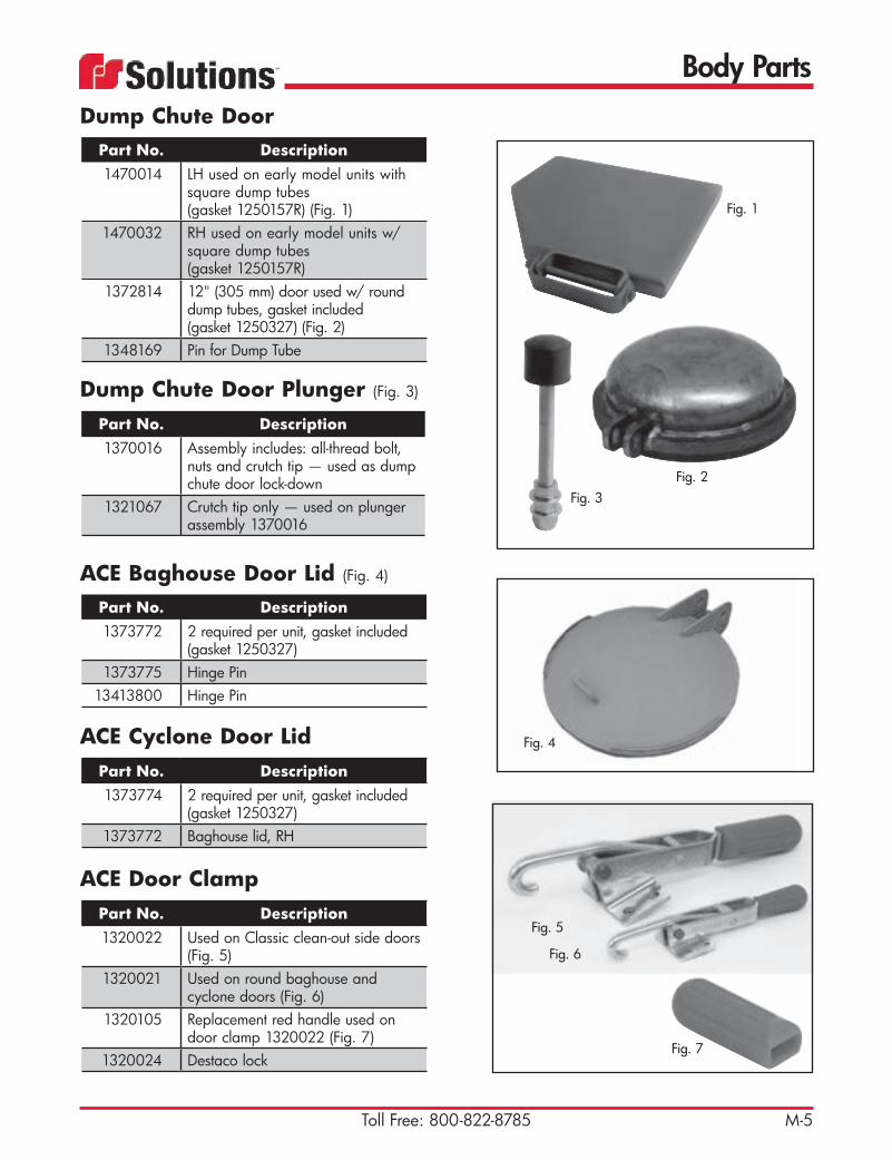
Body Parts
M-5Toll Free: 800-822-8785
Dump Chute Door Plunger (Fig. 3)
Part No. Description1370016 Assembly includes: all-thread bolt,
nuts and crutch tip — used as dump chute door lock-down
1321067 Crutch tip only — used on plunger assembly 1370016
ACE Door ClampPart No. Description1320022 Used on Classic clean-out side doors
(Fig. 5)1320021 Used on round baghouse and
cyclone doors (Fig. 6)1320105 Replacement red handle used on
door clamp 1320022 (Fig. 7)1320024 Destaco lock
Fig. 6
Fig. 5
Fig. 7
ACE Baghouse Door Lid (Fig. 4)
Part No. Description1373772 2 required per unit, gasket included
(gasket 1250327)1373775 Hinge Pin
13413800 Hinge Pin
ACE Cyclone Door LidPart No. Description1373774 2 required per unit, gasket included
(gasket 1250327)1373772 Baghouse lid, RH
Fig. 4
Dump Chute DoorPart No. Description1470014 LH used on early model units with
square dump tubes (gasket 1250157R) (Fig. 1)
1470032 RH used on early model units w/ square dump tubes (gasket 1250157R)
1372814 12" (305 mm) door used w/ round dump tubes, gasket included (gasket 1250327) (Fig. 2)
1348169 Pin for Dump Tube
Fig. 1
Fig. 2Fig. 3

Body Parts
M-6 E-mail: [email protected]
Rear Float Level IndicatorPart No. Description1490750 Assembly — includes shaft, arm,
o-rings, dial, float ball, jam nut and grease fitting
1250076 O-ring used on shaft 1129470 (2 required)
1129470 Shaft — connects indicator dial to float level indicator arm, used in assembly 1490750 (Fig. 1)
1374583 Arm with 1/2" (12.7 mm) threaded connection — uses stainless steel float ball 1320541 (Fig. 2)
1372735 Indicator dial located on exterior of tank — red (Fig. 3)
1170087 Jam nut (Fig. 4)1160475 Dog point screw (Fig. 4)1320541 6" (152 mm) stainless steel float ball
with 1/2" (12.7 mm) connection — used with arm 1374583 (Fig. 5)
1129471 Indicator bushing — carbon steel 5" x 2.5" OD x 1" ID (127 mm x 63.5 mm x 25 mm)
Fig. 3
Fig. 1
Fig. 2
Fig. 4
Fig. 5
Side-Mounted Float Level IndicatorPart No. Description58099D Assembly — includes shaft, arm,
o-rings, dial, float ball, jam nut and grease fitting (Fig. 6)
37131 Float control weldment — pointed arm
37132B Bushing assembly40550 1/2" (12.7 mm) stainless steel
flatwasher41771 1/2" x 11/16" x 3/32" DIA o-ring
(12.7 mm x 17.5 mm x 2.4 mm)86248A Float arm weldment86248B Float arm weldment
31069 Drain hose holder45113 6" (152 mm) stainless steel float ball
used with assembly 58099D16420L 1/8" x 3/4" (3.2 mm x 19 mm)
stainless steel roll pin
Fig. 6

Body Parts
M-7Toll Free: 800-822-8785
Float Level IndicatorUsed on full-opening tailgates.
Part No. Description1320109 With stainless steel float ball1320059 With plastic float ball
Float Ball (Stainless Steel)
Part No. Description1320456 6" (152 mm) with liquid level indicator1320849 9" (228 mm) used on ACE units —
uses float ball cage 137177744388 10" (254 mm) — 18 gauge, 7 lb
1320383 12" (305 mm) used on Classic units — uses float ball cage 1371525
44478 14" (355 mm) used on Classic units — uses float ball cage 1375194
Float Ball (Mild Steel)
Part No. Description1320848 9" (228 mm) used on ACE units —
uses float ball cage 13717771320431 12" (305 mm) used on Classic units —
uses float ball cage 13715251320430 14" (355 mm) used on Classic units —
uses float ball cage 1375194
Float Ball Cage (Mild Steel)
Part No. Description1371777 9" (228 mm) for ACE units1371525 12" (305 mm) for Classic units1375194 14" (355 mm) for Classic units1250413 Rubber sleeve for flost dhut off
TECH TIP: When float balls become worn from years of service, they often fill with material and no longer float. This may cause the unit to carry liquids over into the baghouse and cyclone — resulting in over filling the unit. Check float balls monthly for any signs of wear or damage to ensure proper operation.
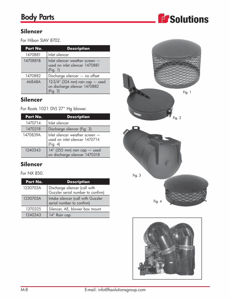
Body Parts
M-8 E-mail: [email protected]
SilencerFor Hibon SIAV 8702.
Part No. Description1470881 Inlet silencer
1470881B Inlet silencer weather screen — used on inlet silencer 1470881 (Fig. 1)
1470882 Discharge silencer — no offset46848A 12-3/4" (324 mm) rain cap — used
on discharge silencer 1470882 (Fig. 2)
SilencerFor Roots 1021 DVJ 27" Hg blower.
Part No. Description1470714 Inlet silencer1470318 Discharge silencer (Fig. 3)
1470839A Inlet silencer weather screen — used on inlet silencer 1470714 (Fig. 4)
1240343 14" (355 mm) rain cap — used on discharge silencer 1470318
SilencerFor NX 850.
Part No. Description1230702A Discharge silencer (call with
Guzzler serial number to confirm)1230703A Intake silencer (call with Guzzler
serial number to confirm)1370325 Silencer, AE, blower box mount1240343 14” Rain cap
Fig. 1
Fig. 4
Fig. 3
Fig. 2

Body Parts
M-9Toll Free: 800-822-8785
Microstrainer (Fig. 1)
Part No. Description1470706 Guzzler 1' 2-3/4" (375 mm) offset1470736 Guzzler 2' 2-3/4" (679 mm) offset1470781 ACE 1' 2-3/4" (375 mm) offset1470705 Center mounted
Boom — Miscellaneous PartsPart No. Description1370055 Boom flange weldment — used on
NX units (Fig. 3)1210558 Boom break gear (Fig. 4)1201007 Boom bearing (Fig.5)1336131 Boom motor gear (Fig. 6)116044B SHCS, 1/2” x 2-1/4” holoch1180070 Washer, 1/2” hi-collar
1160591B SHCS, 1/2” x 2-1/4” UNC L9 Fig. 3
Fig. 4Fig. 5 Fig. 6
Microstrainer Basket (Fig. 2)
Part No. Description1370173 11.19" OD x 10.75” tall
(284 mm x 273 mm) Guzzler Classic microstrainer basket
1372419 10.75" OD x 18.69” tall (273 mm x 475 mm) Guzzler ACE microstrainer basket
TECH TIP: Remove and clean the microstrainer basket weekly of any material or objects that may have collected there. The microstrainer basket acts as protection for the blower to keep any foreign ob-jects from passing into the blower and damaging it.
Fig. 1
Fig. 2

Body Parts
M-10 E-mail: [email protected]
Boom BoxPart No. Description1374597 Used on High Rail, Standard
Guzzler and ACE units1122427 Boom blind flange PL 3/8” x
20-1/2” OD
Bag Hold-Down AssemblyPart No. Description1375516 Used on NX units
ACE Tank Outlet AssemblyPart No. Description1374640 Tank outlet
Related ItemsSee Page G-5 for Float Ball Shut-off Rubber Seat.See Page M-7 for Float Ball Cage.

Body Parts
M-11Toll Free: 800-822-8785
Pin-Wheel LatchManual pin-wheel latch assembly used on half-opening and full-opening tailgates.
Part No. Description1372005A Wing bolt (Fig. 6)
1374573 Wing bolt handle (Fig. 7)1320114 Thrust bearing (Fig. 8)1374218 Wingnut latch kit for
Guzzler w/ offload system
Tailgate ShimPart No. Description11210504 3/8" x 5" x 7"
(9.5 mm x 127 mm x 178 mm) (Fig. 3)
11212338 Lock bracket shim, 5" x 7" x 16 ga. (127 mm x 178 mm) (Fig. 4)
11212339 Lock pin sleeve shim (Fig. 5)
Tailgate Safety Pin (Fig. 1)
Part No. Description1372863 Half-opening, red
Debris Tank Safety Stand (Fig. 2)
Part No. Description1373701 Safety stand, new style
Tailgate Safety PropPart No. Description1375484 Half-opening used on 2007 and
newer units, red1374031 Full-opening
Fig. 6
Fig. 7
Fig. 8
Fig. 1
Fig. 3
Fig. 5Fig. 4
Fig. 2
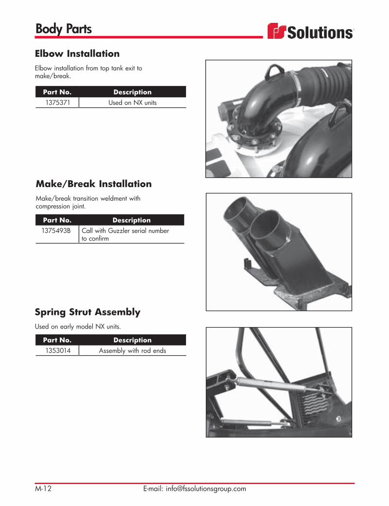
Body Parts
M-12 E-mail: [email protected]
Elbow InstallationElbow installation from top tank exit to make/break.
Part No. Description1375371 Used on NX units
Make/Break InstallationMake/break transition weldment with compression joint.
Part No. Description1375493B Call with Guzzler serial number
to confirm
Spring Strut AssemblyUsed on early model NX units.
Part No. Description1353014 Assembly with rod ends

Body Parts
M-13Toll Free: 800-822-8785
Transfer Case Driveline CoverWith access door to grease transfer case to blower driveline.
Part No. Description1375594A Drivelone cover assembly, Alum.11222211 Bracket, Driveline cover11212637 Dumptube Hanger bracket
Static Ground ReelUsed on all units.
Part No. Description1190282 50' (15 m) orange cable with clamp
1190282A 25' (7.6 m) orange cable with clamp1190282A 25’ (7.6 m) Replacement cable and
connector
Vacuum Relief Basket (Fig. 1)
Part No. Description1375486 4" (101 mm)1375487 6" (152 mm)
Vibrator Bracket
Part No. Description1371869 Mounting bracket for electric and
hydraulic vibrators Fig. 1

Body Parts
M-14 E-mail: [email protected]
IsolatorPart No. Description
71098 Rubber — used on NX units (Fig. 1)1320907 Vibration — used on control panel
(Fig. 2)
Groove Coupler
Part No. Description1281030 Aluminum — used on NX
recovery system1281030A Aluminum groove / groove
coupler
Butterfly LatchPart No. Description1320840 Guzzler — used on the
control panel
Fender Light BracketPart No. Description11220396 Fender light bracket (Fig. 3)11220077 Fender light mount, rear
1126938 Tail light bracket
Fig. 1
Fig. 2
Fig. 3

Body Parts
M-15Toll Free: 800-822-8785
Rear Bumper
Part No. Description1490834 Quick release — used on units
with a sludge pump off-load1373299 Bumper, Guzzler or Ace1373515 Dumptube hanger weldment, 12”
Ace11212637 Dumptube hanger bracket, un-pai1375483 Rope ladder weld, bolt-on Guzzler
rear door platform1373463 ladder support
Cooling FanPart No. Description
48603 Electric — used on NX sound enclosure
Mud FlapPart No. Description1250034 FS Solutions logo — black
rubber with white lettering, 24" x 36" (610 mm x 914 mm)
1290863 Spring-loaded brackets — 2 per set
46661 Anti-sail frame — sold individually, 2 required per truck

Body Parts
M-16 E-mail: [email protected]
Tie Down
Part No. Description1160545 Eye bolt, 5/8” NC - 5”1170100 Nut, eye, bail size 1/2”, tap size
5/8”, Max. work load 3500 lbs.1373403 Baghouse and cyclone tie down
clamp24901 Pin - .625” diam. x 2.25”
1250345 O-ring
Ace Fenders
Part No. Description11219624 Conduit, Steel, 1 EMTX53.
11219625 Conduit, Steel, 1 EMTX22.50011220176 Fender Mounting, Reinforcement11220395 Fender bolt-on sub-frame1374609 Fender Hanger bracket

Blowers
N-1Toll Free: 800-822-8785
With over 30 years experience in working with positive displacement blowers, Guzzler specializes in the supply, repair, service and maintenance of industrial blowers. Our preventive maintenance will ensure that your blowers operate at optimum efficiency and reduce the possibility of failure and breakdown.
Hibon Blowers Part No. Description
1230700 Hibon NX850 (Fig. 2)1230634 Hibon Tri-Lobe SIAV 8702
Holmes Blowers Part No. Description
43444 Holmes 1020
Rebuilt Blowers Part No. Description
44551AR Rebuilt Roots 1024 18" Hg1230403R Rebuilt Roots 1021 DVJ1230700R Rebuilt Hibon NX8501230634R Rebuilt Hibon Tri-Lobe SIAV 8702
Roots Blowers Part No. Description44551A Roots 1024 18" Hg (Fig. 1)
44551 Roots 1024 — vertical1230080 Roots 1024 — horizontal1230081 Roots 1021 15" Hg1230183 Roots 1021 18" Hg1230403 Roots 1021 DJV 27" Hg
230137 Roots 624 — vertical230213 Roots 824 — vertical230242 Roots 827 — vertical
Fig. 2
Fig. 1Robuschi Blowers
Part No. Description49553 Robuschi RBDV145 - 27”

Blowers
N-2 E-mail: [email protected]
Heat Shield Part No. Description
1230247A Blower heat shield — used on 1024 blowers
KeystockPart No. Description1125258 1/2" x 1/2" x 7-1/2"
(12.7 mm x 12.7 mm x 190 mm)
Foot GasketPart No. Description1250375 Teflon® foot gasket — used on
10" (254 mm) blowers
Foot SpringPart No. Description
1320604 Blower foot spring
Filter ElementPart No. Description42431B 10 micron filter for 62634M

Transfer Case
Toll Free: 800-822-8785 O-1
Dana Transfer Case (Fig. 1)
Part No. Description1210001 Model 7921210121 Disconnect assembly —
pump side1210122 Disconnect assembly —
side without pump
Cotta Transfer CasePart No. Description
45446 Model 2059-3
OMSI Transfer CasePart No. Description1211098 For High Rail, creep drive48051A With disconnect — 1:1 gear
ratio48051C For NX — 1:1.7 gear ratio
48051AA Air clutch kit48051AAA Check valve
48051AB O-rings and seals with clutch plates kit
48051AC O-rings and seals kit48051AD Air clutch rebuild kit
Fig. 1
Remanufactured transfer cases are available. Please call for pricing.

Transfer Case
E-mail: [email protected]
Companion FlangePart No. Description1211099 Companion flange, taperlock
IsolatorPart No. Description
42690 Isolator
Transfer Case BracketsUsed on Dana-International transfer case setup.
Part No. Description39225F Mounting bracket (Fig. 1)
1291017 Mount bushing — 4 required per transfer case (Fig. 2)
1291018 Mount insert — 4 required per transfer case (Fig. 3)
61282D Bracket (Fig. 4)
Fig. 1
Fig. 2
Fig. 3
Fig. 4
TECH TIP: To avoid any problems with Dana, OMSI or any other transfer case, always make sure you have the proper air pressure prior to attempt-ing to shift the transfer case and follow all the shift procedures provided with your equipment. It is al-ways better to allow a little more time when engag-ing and disengaging the transfer case than to allow too little.

Transfer Case
Toll Free: 800-822-8785 O-3
OMSI Transfer CaseItem Part No. Description
1 48051CJ Eye — lifting2 * Plug 3 48052AB Washer — copper4 * Plug — magnetic5 * Screw — set6 48051AAT Plug — drain7 * Washer — copper8 * Plug9 * Plug
10 * Housing — 1:1.7 ratio11 * Plug — freeze12 * Plug13 * Elbow — street
14 48051AQ Plug — breather
Item Part No. Description15 48051AH Washer — copper16 48051AJ Plug17 * Conveyer — oil lube diverter18 * Nut19 * Washer — conical20 * Screw — M6x2021 * Washer — lock22 48051AR Screw — M18x45
*Call factory.
Housing, 1:1 Ratio
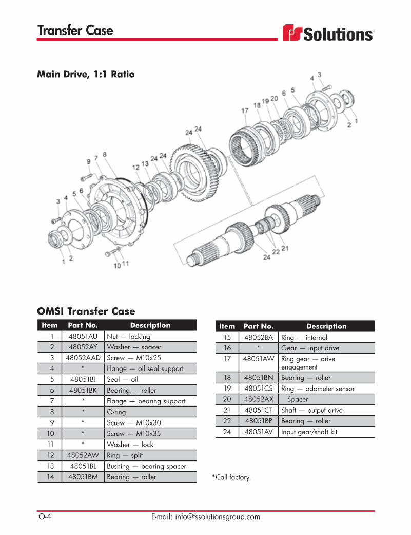
Transfer Case
E-mail: [email protected]
OMSI Transfer CaseItem Part No. Description
1 48051AU Nut — locking2 48052AY Washer — spacer3 48052AAD Screw — M10x254 * Flange — oil seal support5 48051BJ Seal — oil6 48051BK Bearing — roller7 * Flange — bearing support8 * O-ring9 * Screw — M10x30
10 * Screw — M10x3511 * Washer — lock12 48052AW Ring — split13 48051BL Bushing — bearing spacer14 48051BM Bearing — roller
Item Part No. Description15 48052BA Ring — internal16 * Gear — input drive17 48051AW Ring gear — drive
engagement18 48051BN Bearing — roller19 48051CS Ring — odometer sensor20 48052AX Spacer21 48051CT Shaft — output drive22 48051BP Bearing — roller24 48051AV Input gear/shaft kit
*Call factory.
Main Drive, 1:1 Ratio

Transfer Case
Toll Free: 800-822-8785 O-5
OMSI Transfer CaseItem Part No. Description
1 48051DC Screw — M8x502 * Seal — wiper3 * O-ring4 * Housing — shaft support5 48051AK Switch — shaft positioning6 48051AM Cover — wiring protection7 * O-ring8 48051CAA Shaft — shift control9 * Screw — M12x21.5
10 48052BC Washer — copper11 48052BD Spring12 48052BE Ball — 3/8" (9.5 mm)13 48052AG Screw — M8x47 14 48052AH Nut — locking
Item Part No. Description15 48051BB Fork — shifter engagement16 * O-ring17 48051BH Guide — shifter shaft18 * O-ring19 * O-ring20 48052AU Piston — cylinder21 48052AM Nut — locking22 48052AV Housing — cylinder23 * Screw — M8x45
*Call factory.
Shifter Control — Main Drive

Transfer Case
E-mail: [email protected]
OMSI Transfer CaseItem Part No. Description
1 48051CZ Shim — 0.1 mm2 48051CW Shim — 0.2 mm3 48051CX Shim — 0.3 mm4 48051CY Shim — 0.5 mm5 48051BW Bearing — roller6 48051CU Shaft — intermediate drive7 * Gear
*Call factory.
Shaft — Intermediate Drive, 1:1 Ratio
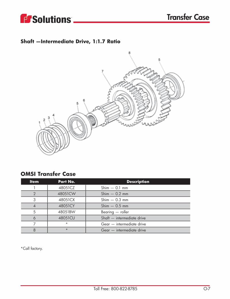
Transfer Case
Toll Free: 800-822-8785 O-7
OMSI Transfer CaseItem Part No. Description
1 48051CZ Shim — 0.1 mm2 48051CW Shim — 0.2 mm3 48051CX Shim — 0.3 mm4 48051CY Shim — 0.5 mm5 48051BW Bearing — roller6 48051CU Shaft — intermediate drive7 * Gear — intermediate drive8 * Gear — intermediate drive
*Call factory.
Shaft —Intermediate Drive, 1:1.7 Ratio

Transfer Case
E-mail: [email protected]
OMSI Transfer CaseItem Part No. Description
1 48051CB Nut — locking2 * Washer — spacer3 48052AAD Screw — M10x254 * Flange — oil seal support5 48052AAA Seal — oil6 48051CZ Shim — 0.1 mm7 48051CW Shim — 0.2 mm8 48051CX Shim — 0.3 mm9 48051CY Shim — 0.5 mm
10 48051BU Bearing — roller11 * Shaft — output drive12 * Gear — output drive13 48051BW Bearing — roller14 48052AO O-ring
Item Part No. Description15 * Flange — bearing support16 * Washer — lock17 * Screw — M10x3518 * Screw — M6x2019 * Conveyer — oil lube diverter20 * Washer — conical21 * Nut — bearing22 * Spacer — output shaft23 * Spacer — output shaft
*Call factory.
Upper Output Shaft, 1:1.7 Drive

Transfer Case
Toll Free: 800-822-8785 O-9
Shaft —Output at Front of PTO, 1:1 Ratio
OMSI Transfer CaseItem Part No. Description
1 48051CB Nut — locking2 * Ring — spacer3 48052AAD Screw — M10x254 * Cover — support5 48052AAA Seal — oil6 48051CZ Shim — 0.1 mm7 48051CW Shim — 0.2 mm8 48051CX Shim — 0.3 mm9 48051CY Shim — 0.5 mm
10 48051BU Bearing — roller11 * Shaft — output drive12 * Gear13 48051BW Bearing — roller14 48052AO O-ring
Item Part No. Description15 * Flange — support16 * Washer — lock17 * Screw — M10x3518 * Screw — M6x2019 * Conveyer — oil20 * Washer — conical21 * Nut — bearing22 * Ring — spacer

Transfer Case
E-mail: [email protected]
Item Part No. Description1 * Screw — M10x352 * Washer — lock3 * Cover
Item Part No. Description1 * Washer — lock2 * Screw — M10x303 * Cover4 * Washer — lock5 * Screw — M10x35
*Call factory.
OMSI Transfer CaseItem Part No. Description
1 48051CP Flange — drive SAE 1600-1800
2 * Flange — drive SAE 1610
OMSI Transfer Case
OMSI Transfer CaseCover Plate, upper
Cover, intermediate output (rear side of PTO)

Water Pump
Toll Free: 800-822-8785 P-1
• Triplex plunger design provides smoother liquid flow.
• V-Packings are completely lubricated and cooled by the liquid being pumped.
• Special ported manifold permits an external flush liquid providing cooling for hi-temp liquids and lubrication for low lubricity liquids.
• Lubricated Lo-Pressure Seals provide double protection against external leakage.
• Oil bath crankcase assures optimum lubrication.
• Close tolerance concentricity of the ceramic plunger offers perfect alignment and maxi-mizes seal life.
48047L
48047N 20 gpm Pump
Features
20 gpm Pump
10 gpm Pump

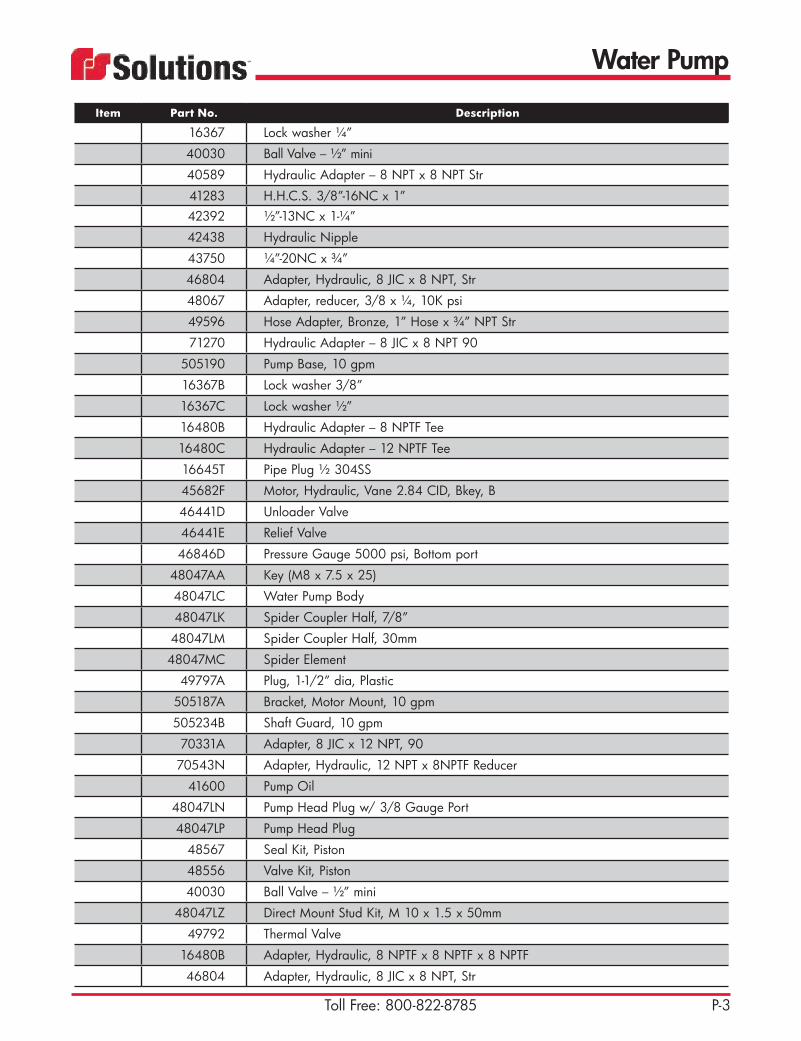
Water Pump
Toll Free: 800-822-8785 P-3
Pump – 10 gpm Item Part No. Description
16367 Lock washer ¼”
40030 Ball Valve – ½” mini
40589 Hydraulic Adapter – 8 NPT x 8 NPT Str
41283 H.H.C.S. 3/8”-16NC x 1”42392 ½”-13NC x 1-¼”
42438 Hydraulic Nipple
43750 ¼”-20NC x ¾”
46804 Adapter, Hydraulic, 8 JIC x 8 NPT, Str
48067 Adapter, reducer, 3/8 x ¼, 10K psi
49596 Hose Adapter, Bronze, 1” Hose x ¾” NPT Str
71270 Hydraulic Adapter – 8 JIC x 8 NPT 90
505190 Pump Base, 10 gpm
16367B Lock washer 3/8”
16367C Lock washer ½”
16480B Hydraulic Adapter – 8 NPTF Tee
16480C Hydraulic Adapter – 12 NPTF Tee
16645T Pipe Plug ½ 304SS
45682F Motor, Hydraulic, Vane 2.84 CID, Bkey, B
46441D Unloader Valve
46441E Relief Valve
46846D Pressure Gauge 5000 psi, Bottom port
48047AA Key (M8 x 7.5 x 25)
48047LC Water Pump Body
48047LK Spider Coupler Half, 7/8”
48047LM Spider Coupler Half, 30mm
48047MC Spider Element
49797A Plug, 1-1/2” dia, Plastic
505187A Bracket, Motor Mount, 10 gpm
505234B Shaft Guard, 10 gpm
70331A Adapter, 8 JIC x 12 NPT, 90
70543N Adapter, Hydraulic, 12 NPT x 8NPTF Reducer
41600 Pump Oil
48047LN Pump Head Plug w/ 3/8 Gauge Port
48047LP Pump Head Plug
48567 Seal Kit, Piston
48556 Valve Kit, Piston
40030 Ball Valve – ½” mini
48047LZ Direct Mount Stud Kit, M 10 x 1.5 x 50mm
49792 Thermal Valve
16480B Adapter, Hydraulic, 8 NPTF x 8 NPTF x 8 NPTF
46804 Adapter, Hydraulic, 8 JIC x 8 NPT, Str

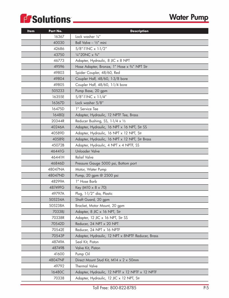
Water Pump
Toll Free: 800-822-8785 P-5
Item Part No. Description
16367 Lock washer ¼”
40030 Ball Valve – ½” mini
42686 5/8”-11NC x 1-1/2”
43750 ¼”-20NC x ¾”46773 Adapter, Hydraulic, 8 JIC x 8 NPT
49596 Hose Adapter, Bronze, 1” Hose x ¾” NPT Str
49803 Spider Coupler, 48/60, Red
49804 Coupler Half, 48/60, 1-3/8 bore
49805 Coupler Half, 48/60, 1-1/4 bore
505233 Pump Base, 20 gpm
16355E 5/8”-11NC x 1-1/4”
16367D Lock washer 5/8”
16475D 1” Service Tee
16480J Adapter, Hydraulic, 12 NPTF Tee, Brass
20344R Reducer Bushing, SS, 1-1/4 x ½
40246A Adapter, Hydraulic, 16 NPT x 16 NPT, Str SS
40589D Adapter, Hydraulic, 16 NPT x 12 NPT, Str
40589J Adapter, Hydraulic, 16 NPT x 12 NPT, Str Brass
45072B Adapter, Hydraulic, 4 NPT x 4 NPTF, SS
46441G Unloader Valve
46441H Relief Valve
46846D Pressure Gauge 5000 psi, Bottom port
48047NA Motor, Water Pump
48047ND Pump, 20 gpm @ 2500 psi
48299A 1” Hose Barb
48749FG Key (M10 x 8 x 70)
49797A Plug, 1-1/2” dia, Plastic
505234A Shaft Guard, 20 gpm
505238A Bracket, Motor Mount, 20 gpm
70338J Adapter, 8 JIC x 16 NPT, Str
70338R Adapter, 12 JIC x 16 NPT, Str SS
70542D Reducer, 24 NPT x 20 NPT
70542E Reducer, 24 NPT x 16 NPTF
70543P Adapter, Hydraulic, 12 NPT x 8NPTF Reducer, Brass
48749A Seal Kit, Piston
48749B Valve Kit, Piston
41600 Pump Oil
48047NF Direct Mount Stud Kit, M14 x 2 x 50mm
49792 Thermal Valve
16480C Adapter, Hydraulic, 12 NPTF x 12 NPTF x 12 NPTF
70338 Adapter, Hydraulic, 12 JIC x 12 NPT, Str


Sludge Pump
Q-1Toll Free: 800-822-8785
No matter what the material, if it can flow, the SLUDGE GUZZLER™ hydraulic submersible pump will pump it.Continuously. Reliably. Completely. Dollar for dollar, SLUDGE GUZZLER™ provides unsurpassed pump-ing power and versatility to meet all your pumping needs. It is ideal for pumping large volumes of water, mud, sewage, silt and other solid laden liquids that cannot be pumped with conventional suction lift pumps. Built for continuous use under the most demanding industrial and municipal conditions, SLUDGE GUZZLER™ will pump in any position, even upside down.The SLUDGE GUZZLER™ is designed for ease of use and dependable operation. It is lightweight, sets up quickly, and can run dry without damage. The hydraulic system permits variable flow control, minimizing wear on the power unit and conserving fuel. Readily available replacement parts keep downtime and costs to a minimum. When combined with an industrial vacuum loader or liquid vacuum tanker, the SLUDGE GUZZLER™ is a cost effective addition that increases your service capabilities.
Pump HeadPart No. Description1400050 4" (101 mm) — standard1410047 6" (152 mm) — standard1400051 4" (101 mm) — super1410048 6" (152 mm) — super

Sludge Pump
Q-2 E-mail: [email protected]
4
2
1
357
689
10
11131214
161517181920
21
28
31
22
25
36
30
32
23
26
35
33
37
24
34
27 29
Note: Part numbers and parts are subject to change.
4" (101 mm) Sludge Pump

Sludge Pump
Q-3Toll Free: 800-822-8785
Item Part No. Description1 1400002W Motor — hydraulic (super)
1400001W Motor — hydraulic (standard)2 1200295 Flange — 4-bolt pump3 1400006 O-ring — upper 4 1400033 Internal snap ring5 1400024 Ball bearing — upper6 1400023W Shaft7 1400025 Ball bearing — lower8 1400049 Bearing carrier assembly9 1400026 Seal assembly — rotary
10 1400014W Seal holder11 1400037 Seal — lip (super)
1400037 Seal — lip (standard)12 1400036 O-ring — S/H13 20937 O-ring — B/C (super)
20937 O-ring — B/C (standard)14 1400016 Internal snap ring — lower15 1400015W Flinger16 1400048 Impeller assembly — fabricated (super)
1400047 Impeller assembly — fabricated (standard)17 1400022 Key18 1180030 Washer19 1170036 Nut — self-locking20 1400046 Volute housing21 1400045 Screen assembly22 1160043 Bolt — hex head (2)23 1170007 Nut — hex (2)24 1180010 Lockwasher (2)25 1160175 Bolt — hex, stainless steel (12)26 1180004 Lockwasher (15)27 1180009 Washer28 1200163 Elbow — male (P)29 46245D Camlock — 4" (101 mm) (P)30 1200253 Quick coupling — female (P)31 1200134 Reducing bushing (R)32 16479D Street elbow (R)33 70542J Reducer bushing (R)34 1200254 Quick coupling — female (R)35 1160174 Bolt — hex head36 1180006 Washer37 402446 Hex nipple
4" (101 mm) Sludge Pump

Sludge Pump
Q-4 E-mail: [email protected]
Note: Part numbers and parts are subject to change.
4
2
1
357
689
10
11131214
161517181920
21
28
31
22
25
36
30
32
23
26
35
37
33
24
34
27 29
6" (152 mm) Sludge Pump
Q-4

Sludge Pump
Q-5Toll Free: 800-822-8785
Item Part No. Description1 1410002 Motor — hydraulic (super)
1410001 Motor — hydraulic (standard)2 1410004 Port block (2)3 1410007 O-ring — upper 4 1410029 Internal snap ring5 1410023 Ball bearing — upper6 1410022W Shaft7 1410024 Ball bearing — lower8 1410045 Bearing carrier assembly9 1410025 Seal assembly — rotary
10 1410013 Seal holder11 1410033 Seal — lip12 410031 O-ring — S/H13 1410030 O-ring — B/C14 1410015 Internal snap ring — lower15 1410014 Flinger16 1410044 Impeller assembly — fabricated (super)
1410043 Impeller assembly (standard)17 10075M Key18 1410016 Washer19 1170037 Nut — self-locking20 1410049 Volute housing21 1410041 Screen assembly22 1160054 Bolt — hex head (2)23 1170009 Nut — hex (2)24 1180012 Lockwasher (2)25 1160176 Bolt — hex, stainless steel (12)26 1180006 Lockwasher (15)27 1180011 Washer28 1200478 Elbow — male (P)29 1280107 Camlock — 4" (101 mm) (P)30 1200371 Quick coupling — male (P)31 20295 Reducing bushing (R)32 10453E Street elbow (R)33 16864D Hex nipple (R)34 1200373 Quick coupling — male (R)35 1160177 Bolt — hex head36 1180010 Washer37 70542E Reducing bushing (R)
6" (152 mm) Sludge Pump


Driveline
R-1Toll Free: 800-822-8785
OMSI-Hibon Driveline AssemblyPart No. Description86592G Upper driveline assembly
44665 Flanged yoke (Fig. 1)43961 U-joint (Fig. 2)48356 Yoke shaft for a 1610 (Fig. 3)
1211031 Bore flange43962A Slip yoke assembly for a 1610 (Fig.
4)
Dana Driveline AssemblyPart No. Description1350021 Driveline assembly
44665 Flanged yoke (Fig. 1)43961 U-joint (Fig. 2)
1210003 Slip yoke1210002 Yoke shaft — male1210008 3/8" x 1-3/16" (9.5 mm x 30.2 mm)
bolt — 16 required per flange1210009 3/8" (9.5 mm) nut — 16 required
per flange
Fig. 2Fig. 1
Fig. 3
Fig. 4
TECH TIP: Drivelines should be greased every 25 hours or weekly at a minimum. Poor maintenance and failure to grease drivelines will cause premature driveline failure and could cause blower failure.

Driveline
R-2 E-mail: [email protected]
Driveshaft AssemblyPart No. Description
48016T For NX unit
Upper DrivelinePart No. Description
86592 Used on a 1021 DVJ86592N Used on NX ACE (Fig. 3)
Bore FlangePart No. Description1210014 6" (152 mm) used on select
blowers — call with Guzzler serial number to confirm
1125257 5.5" (140 mm) keystock used on 6" (152 mm) bore flange 1210014
1210015 8" (203 mm) used on select blowers — call with Guzzler serial number to confirm
1125258 7.5" (191 mm) keyway used on 8" (230 mm) bore flange 1210015
Fig. 2
Fig. 1
Cotta and OMSI Transfer CasePart No. Description
48017F Flange yoke (Fig. 1)48017B U-joint (Fig. 2)
Fig. 3

Decals
S-1Toll Free: 800-822-8785
NX LogoPart No. Description
1320241 NX body logo (Fig. 1)
ACE LogosPart No. Description1320742 ACE body logo — black (Fig. 2)1320743 ACE body logo — white
Decal KitsPart No. Description47047HZ Float level indicator —
full to empty1800131A Guzzler NX1800134A Guzzler ACE1800135A Guzzler Classic1800141A HXX PD1800160A HXX fan1800177A HXX Prodigy PD
Classic LogosAll logos are 11" x 47" (279 mm x 1194 mm).
Part No. Description1320973 Classic body logo — black (Fig. 3)
1320973A Classic body logo — brown 1320973B Classic body logo — chrome1320973C Classic body logo — silver
1320974 Classic body logo — white (Fig. 4)
1320973 - 11” x 47“ - black1320973A - 11” x 47“ - brown1320974 - 11” x 47“ - white1320973B - 11" x 47" - chrome1320973C - 11" x 47" - Silver Metallic - Dupont C9339
LTR. Revision By Date ECN No.
0 Initial release - - -
This document contains material and/or information which is the property of Vactor Manufacturing Inc., and supplied only on a confidential basis. No transmittal or disclosure shall be made to any person, firm, or corporation without written approval of Vactor Manufacturing Inc.. The controlled master copy of this document resides in electronic format. All printed copies of thisdocument are UNCONTROLLED.
VACTOR Manufacturing Inc. STREATOR, IL.
NAMELOGO,GUZZLER ACE,BLACK
.ON TRAPELACSETAD.RDAC 4-11-2006 NONE 1320742
DIMS. IN INCHESTOLERANCES UNLESS NOTED +/- .032 per foot
ENG. STANDARDS
E0010 - Decal layout specificationsE0013 - Vinyl film - body logos
20-1/8" wide x 7” tall
A Removed Guzzler Manufacfuring, Inc. AC 4-11-2006 6326
Vactor No. 1800124
Approx size 11.7” by 48”
Fig. 1
Fig. 2
Fig. 4
Fig. 3

Decals
S-2 E-mail: [email protected]
HXX LogosPart No. Description
47047JF HXX — black (Fig. 1)47047JT HXX — white (Fig. 2)
47047JTA HXX — silver47047KP HXX — no dig decal
49206 HXX Prodigy for light colored units — 30" x 52" (762 mm x 1321 mm) (Fig. 3)
49206A HXX Prodigy for light colored units — 16" x 28" (406 mm x 711 mm)
49206B HXX Prodigy for dark colored units — 30" x 52" (762 mm x 1321 mm)
49206C HXX Prodigy for dark colored units — 16" x 28" (406 mm x 711 mm)
47047JF - black/blue47047JT - white/blue w/white outline47047JTA - silver
LTR. Revision By Date ECN No.
0 Initial release AC 1-5-2007 6682
This document contains material and/or information which is the property of Vactor Manufacturing Inc., and supplied only on a confidential basis. No transmittal or disclosure shall be made to any person, firm, or corporation without written approval of Vactor Manufacturing Inc.. The controlled master copy of this document resides in electronic format. All printed copies of thisdocument are UNCONTROLLED.
VACTOR Manufacturing Inc. STREATOR, IL.
NAMELOGO,HXX PRODIGY 30X52
.ON TRAPELACSETAD.RDAC 1-5-2007 NONE 49206
DIMS. IN INCHESTOLERANCES UNLESS NOTED +/- .032 per foot
ENG. STANDARDS
E0010 - Decal layout specificationsE0013 - Vinyl film body logos
51.23" wide x 29.84" tallNote: Illustrator file is actual size
Fig. 1
Fig. 2
Fig. 3

HXX Replacement Parts
T-1Toll Free: 800-822-8785
Part No. Description49785 12v 400,000 BTU Water Heater
49785A High-altitude Burner Nozzle -Required for 4,000-8000 ft elevations
49785B High-altitude Burner Nozzle - Required 8000+ ft elevations
Alkota Water Heaters
Part No. Description49830 Thermostat, Water Heater
49830A Temperature Gauge, Water Heater
49830B Burner Gasket, Water Heater49830C Burner Motor, 400,000 BTU Heater49830D Burner Motor, 800,000 BTU Heater49830E Igniter, 400,000 BTU Heater49830F Igniter, 800,000 BTU Heater
49830G Fuel Filter, Water Heater49830H Deck Insulation, 400,000 BTU Heater49830J Deck Insulation, 800,000 BTU Heater
49830K Domed Hood, 400,000 BTU Heater49830L Domed Hood, 800,000 BTU Heater
49830M Fuel Pump, Water Heater49830N Power Switch, 400,000 BTU Heater49830P Power Switch, 800,000 BTU Heater49830R Relief Valve, Water Heater49830S Pressure Switch, Water Heater
Water Heater Replacement Parts
400,000 BTU Water Heater
Part No. Description49786 110v 800,000 BTU Heater
(Requires inverter)49978 12v 400,000 BTU Water Heater
(Does not require inverter)
49786A High-altitude Burner Nozzle - Required for 4,000-8000 ft elevations
49786B High-altitude Burner Nozzle - Required 8000+ ft elevations
800,000 BTU Water Heater

HXX Replacement Parts
T-2 E-mail: [email protected]
Alkota Water HeaterItem Part No. Description
1 49830K ASSEMBLY, COIL TOP - 18" W/INSUL 2 49830H INSULATION, CERAMIC FIBER - 1 X 18" DIA W 4 1/4 3 WELDMENT, PANEL-CONTROL, 18" VACTOR 4 SHIELD, GAUGE-VACTOR 18" 5 VALVE, RELIEF - 3/8NPT INLET 1/4" BARB 90 DEG, 6 GPM, 1000-6000 PSI (SS BARB)6 BUSHING, 3/4MNPT - 3/8FNPT PIPE GS HEX HEAD 7 CAP, PIPE - 3/8FNPT SCH80 ZP HEX HEAD 8 ADAPTER,1/2MPT X 1/2FPT,PLATED STEEL9 CROSS, 1/2FNPT HI PRESS PIPE
10 ELBOW, 3/4FMPT - 90 DEG, FORGED, HI PRESSURE 11 TEE, 1/2FNPT PIPE HI PRESSURE 5000 PSI 12 TEE, 3/4FNPT HI PRESSURE PIPE 13 NIPPLE,HEX-REDUCING-3/8"X 1/2" 14 NIPPLE,3/4MNPT-12 1/2" PS PIPE 15 SCREW, CAP - 1/4 - 20UNC X 3/4 IND HEX SERR WASHER HD Z.P16 NUT, LOCK - 1/4-20 UNC, SERRATED FLANGE, ZP, HEX 17 NUT,LOCK-3/8-16UNC HEX SERRATED FLANGE ZINC 18 HOSE, 1/2" X 28" COUPLED 19 49830T WELDMENT,COIL-FINAL,SCH80 18", 3/4" PIPE,HRS 20 ASSEMBLY, PANEL-CONTROL (VACTOR) 18" 21 49830C ASSEMBLY, BURNER-W/O SOL, 12 VOLT 22 WELDMENT, BASE- WH - OIL FIRED 18" 23 WELDMENT, BRACKET - NIPPLE (24" VACTOR) 24 THERMOMETER, 3" DIAL DAMPENED, 4" STEM, 50-500DF, 1/2" NPT, 3000 PSI

HXX Replacement Parts
T-3Toll Free: 800-822-8785
Alkota Water HeaterItem Part No. Description
1 INSULATION, 1" X 5"ID X 23 1/2"OD, CERAMIC FIBER
2 49830L ASSEMBLY, COIL TOP 23-5/8" ID, W/11OD STACK 3 WELDMENT, PANEL-CONTROL 4 WELDMENT, PANEL-MOUNT 5 SHIELD, GAUGE-VACTOR 24" 6 49830R VALVE, RELIEF - 3/8NPT INLET 1/4" BARB 90 DEG, 6 GPM, 1000-6000 PSI (SS BARB)7 BUSHING, 3/4MNPT - 3/8FNPT PIPE GS HEX HEAD 8 BUSHING, 3/4MNPT - 1/2FNPT PIPE HEX PS 9 CAP, PIPE - 3/8FNPT SCH80 ZP HEX HEAD
10 CROSS, 1/2FNPT HI PRESS PIPE 11 CROSS, 3/4FNPT STEEL 12 ELBOW, 3/4FMPT - 90 DEG, FORGED, HI PRESSURE 13 PLUG, PIPE - 3/4MNPT GS SQUARE HEAD CORED 14 TEE, 3/4FNPT HI PRESSURE PIPE 15 NIPPLE,HEX-REDUCING-3/8"X 1/2" 16 NIPPLE,3/4MNPT-12 1/2" PS PIPE 17 SCREW, CAP - 1/4 - 20UNC X 3/4 IND HEX SERR WASHER HD Z.P 18 NUT, LOCK - 1/4-20 UNC, SERRATED FLANGE, ZP, HEX 19 NUT,LOCK-3/8-16UNC HEX SERRATED FLANGE ZINC 20 HOSE, 1/2" X 28" COUPLED 21 49830U WELDMENT, COIL - FINAL, SCH80 22 WELDMENT, BRACKET - NIPPLE (24" VACTOR) 23 ASSEMBLY, PANEL-CONTROL (VACTOR) 24 49830D ASSEMBLY, BURNER-W/SOL, 115 VOLT 25 WELDMENT, BASE - 24" OIL FIRED (VACTOR) 26 49830A THERMOMETER, 3" DIAL DAMPENED, 4" STEM, 50-500DF, 1/2" NPT, 3000 PSI27 INSULATION, CERAMIC FIBER- 1 x 4 x 73
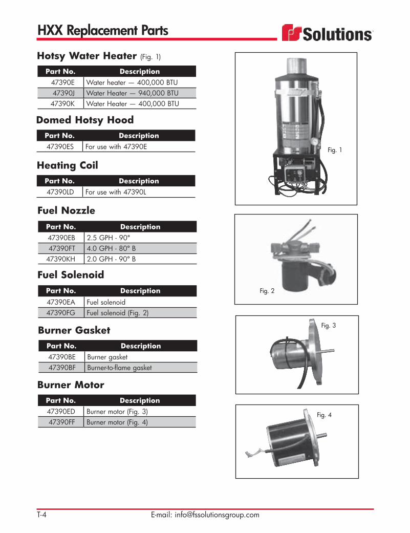
HXX Replacement Parts
T-4 E-mail: [email protected]
Hotsy Water Heater (Fig. 1)
Part No. Description47390E Water heater — 400,000 BTU47390J Water Heater — 940,000 BTU
47390K Water Heater — 400,000 BTU
Burner GasketPart No. Description47390BE Burner gasket47390BF Burner-to-flame gasket
Burner MotorPart No. Description47390ED Burner motor (Fig. 3)47390FF Burner motor (Fig. 4)
Fuel NozzlePart No. Description47390EB 2.5 GPH - 90º47390FT 4.0 GPH - 80º B
47390KH 2.0 GPH - 90º B
Fuel SolenoidPart No. Description47390EA Fuel solenoid47390FG Fuel solenoid (Fig. 2)
Fig. 2
Fig. 3
Fig. 1
Heating CoilPart No. Description47390LD For use with 47390L
Fig. 4
Domed Hotsy HoodPart No. Description47390ES For use with 47390E

HXX Replacement Parts
T-5Toll Free: 800-822-8785
Hotsy 400,000 BTU Water HeaterItem Part No. Description
1 * Outlet manifold assembly2 47390H High-pressure relief valve3 * Relief hose4 47390EK High-pressure outlet
hose assembly5 47390AJ Temperature gauge6 47390EL Primary burner control7 47390JC Thermostat/thermo-couple
assembly8 47390AK Hour meter9 * Burner switch – 12V DC
10 47390EC Ignitor11 47390EF Fuel filter12 47390ET Fuel pump
Item Part No. Description13 47390AR Green light – 12V DC14 47390AS Yellow light – 12V DC15 47390AT Blue light – 12V DC16 47390EA Fuel solenoid17 47390EB Fuel nozzle18 45277 Pressure switch19 * Cable – 2-wire
*Call factory.

HXX Replacement Parts
T-6 E-mail: [email protected]
Fuel Filter AssemblyPart No. Description47390EF For use with 47390E
Fuel PumpPart No. Description47390ET Fuel pump, burner 400K BTU (Fig.
2)47390FA Fuel pump, burner 900K BTU
Primary ControlPart No. Description47390EL Primary control (Fig. 4)47390FE Primary control
Thermostat ControlPart No. Description47390JA Manual thermostat control47390JC Manual thermostat control47390JB Temperature gauge47390H High-temperature relief valve
(Fig. 3)
Photo CellPart No. Description47390BD Photo cell (Fig. 1)47390FB Photo cell flame sensor
Fig. 3
Fig. 2
Fig. 4
Fig. 1
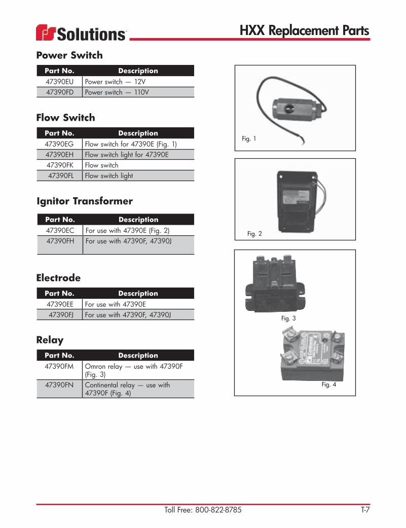
HXX Replacement Parts
T-7Toll Free: 800-822-8785
ElectrodePart No. Description47390EE For use with 47390E47390FJ For use with 47390F, 47390J
Power SwitchPart No. Description47390EU Power switch — 12V47390FD Power switch — 110V
RelayPart No. Description47390FM Omron relay — use with 47390F
(Fig. 3)47390FN Continental relay — use with
47390F (Fig. 4)
Flow SwitchPart No. Description47390EG Flow switch for 47390E (Fig. 1)47390EH Flow switch light for 47390E47390FK Flow switch47390FL Flow switch light
Ignitor Transformer
Part No. Description47390EC For use with 47390E (Fig. 2)47390FH For use with 47390F, 47390J
Fig. 2
Fig. 3
Fig. 4
Fig. 1

HXX Replacement Parts
T-8 E-mail: [email protected]
HosePart No. Description47390EJ Water inlet hose (Fig. 1)47390EK Water outlet hose (Fig. 2)47390FQ Flow bypass hose (Fig. 3)
Hotsy Miscellaneous Replacement Parts
Part No. Description47390EM Watlow — temperature controller47390EN Power supply — 12V DC to
24V DC47390EP Thermo-couple type J — use with
47390E47390EQ PVC type J wire - use with 47390E
Final FilterAir filter.
Part No. Description1140363A 19.6" OD x 14" ID x 28.5" tall
(497.8 mm x 355.6 mm x 723.9 mm), round style for HXX with blower (Fig. 4)
1140363B 19.6" OD x 14" ID x 21.5" tall(497.8 mm x 355.6 mm x 546.1 mm), round style for HXX Prodigy
1140467D 20" x 30" x 3.5" (508 mm x 762 mm x 88.9 mm), old square style for HXX with blower (Fig.5)
Fig. 4
Fig. 5
TECH TIP: Gaskets should be used with all filters to prevent air leaks that can cause material to fall out in the hose rather than being carried to the debris body.
Fig. 2
Fig. 1
Fig. 3

HXX Replacement Parts
T-9Toll Free: 800-822-8785
Seal KitPart No. Description48749A For Cat 356048567 For Cat 660
46441EA Buna-N seal kit for relief valve 46441E
46441EB Viton seal kit for relief valve 46441E
Valve KitPart No. Description48749B For Cat 356048556 For Cat 660 — 2 required
SpiderPart No. Description
48565 For motor coupling on Cat 66048047MC For motor coupling on Cat 3560
ValvesPart No. Description46441D Unloader valve for Cat 660 —
pump 48947L, 10 gpm (38 lpm)46441E Relief valve for Cat 66046441G Unloader valve for Cat 3560 —
pump 48947N, 20 gpm (76 lpm)46441H Relief valve for Cat 3560
Ignition SwitchPart No. Description
47773 Ignition Switch

HXX Replacement Parts
T-10 E-mail: [email protected]
Part No. Description500619F Trigger gun assembly used with
digging lances features 1/2" (12.7 mm) quick-disconnect fittings
Safety Shutoff Valve Assembly
Part No. Description500619A 1/2" x 83" (12.7 mm x 2108 mm)500619B 1/2" x 108" (12.7 mm x 2743
mm)500619C 1/2" x 48" (12.7 mm x 1219 mm)500619E 1/2" x 83" (12.7 mm x 2108 mm)
with nozzle
Digging Lance Pipe Assembly (Fig. 1)
Part No. Description89444 Fiberglass digging lance kit
Digging Lance KitLightweight design. Includes 2 nozzle guard assemblies.
Part No. Description20188M 1/2" (12.7 mm) male (HXX)
(Fig. 2)20188L 1/2" (12.7 mm) female (HXX)
(Fig. 3)
Quick-DisconnectUsed to connect digging lances for HXX units.
Fig. 3Fig. 2
Fig. 1

HXX Replacement Parts
T-11Toll Free: 800-822-8785
Part No. Description89714 3.2 gpm (12.1 lpm), 2 nozzles in
straight pattern (Fig. 3)89714A 4.8 gpm (1807 lpm), 3 nozzles in
triangle pattern89714B 9.6 gpm (36.3 lpm), 3 nozzles in
triangle pattern89714C 16.5 gpm (62.5 lpm), 3 nozzles in
triangle pattern89714D 6.4 gpm (24.2 lpm), 2 nozzles in
straight pattern
Nozzle with Guard AssemblyAll parts rated at 2500 psi (172 bar).
Fig. 3
Part No. Description89713 White polyethylene nozzle guard
Nozzle Tube Guard
Part No. Description48685 3-4 gpm (11.4-15.1 lpm)
(Fig. 1)48687 6-7 gpm (22.7-26.5 lpm)
(Fig. 2)
Rotator NozzleUsed on HXX Units.
Fig. 2Fig. 1
Part No. Description48047 CAT Pump 660, 10gpm
(pump only)45682F Motor, HYD, Vane, 2.84 cid, bkey
B48047LK Spider Coupler, half, 7/8”
48047MC Spider Element (48047L)64987BS Schem, Water, Hydro-Ex, Handgun47366CA Hose Assy’ Hyd 3/8X600
46438L Hose Reel - 3000 psi
CAT Pump


Safety
U-1Toll Free: 800-822-8785
Your partners in working smart and safe!FS Solutions is your one-stop resource for today’s best and most popular safety equipment for use in industrial vacuum operations. From safety manuals to personal protective clothing and gear, we’ve got you covered!Safety is no accident! Identify hazards … Warn against hazards …Protect against hazards.
Steel Toe Rubber BootsPart No. Description
1310340A Sold per pair
Rain SuitsPart No. Description
1310472A Small - XL — 20 per case1310472B XXL — 20 per case1310472C 3XL — 20 per case1310472D 4XL — 20 per case
Tyvek® SuitsPart No. Description
1311231A Small - XL — 25 per case1311231B XXL — 25 per case1311231C 3XL — 25 per case1311231D 4XL — 25 per case

Safety
U-2 E-mail: [email protected]
Part No. Description1310087A Shield — sold individually1310086A Bracket — sold individually
Face Shield
Part No. Description1310729A MSA Hard hat — sold individually
Hard Hat
Safety GlassesPart No. Description
1310088A Clear — 12 per case (Fig. 5)1310088B Tinted — 12 per case (Fig. 4)
GlovesPart No. Description
1310988A Jersey gloves — 12 pair (Fig. 1)1310988B Split cowhide gloves — 12 pair
(Fig. 3)1310988C PVC gloves — 12 pair (Fig. 2)
Fig. 4
Fig. 5
Fig. 1
Fig. 2
Fig. 3
Part No. Description1310349A 100 pair — corded
Ear Plugs

Safety
U-3Toll Free: 800-822-8785
Part No. Description1281038 58" x 58" (1473 mm x 1473 mm)
— designed to protect workers who could come in contact with harmful electrical current. Use of mat is required by OSHA 1910.269.
Non-Skid Equi Mat
Part No. Description46635B Includes: Plastic tool box, ball peen
hammer, leather work gloves, safety manual, rubber mallet, hack saw, crescent wrench, wrecking bar, flashlight, tape measure, pliers, wire cutters, terminal crimpers, vise grips, utility knife, duct tape, electri-cal tape, wire terminals, Phillips screwdriver, standard screwdriver
Vacuum Truck Operator’s Tool Box
Duct TapePart No. Description
1310261A 2” x 60 yards (76 mm x 55 m) — 24 per case


Maintenance
V-1Toll Free: 800-822-8785
Recommended Oils, Lubricants and Fluids — All Guzzler and HXX Models
Hydraulic SystemThe hydraulic system leaves the factory filled with Castrol Hydraulic Plus Blue 46 (*) oil. This fluid is recommended for all normal operating conditions to 95°F ambient. For continuous operation above 95°F (35ºC) to 105°F (41ºC) ambient, Castrol Hydraulic Plus Blue 68 is recommended. For continuous opera-tion above 105°F (41ºC) ambient, consult the factory. For operation from -20°F (-29ºC) to 70°F (21ºC) ambient, use the Castrol Hydraulic Plus Blue 32 oil. For continuous operation below -20°F (-29ºC) ambi-ent, consult the factory.Other hydraulic oils, if used, should be a quality product carefully selected with assistance from a cred-ible supplier. The oil should include thermal stability, sheer stability, low-temperature fluidity, anti-wear, anti-corrosion, anti-foaming and seal conditioning characteristics. Consult the factory before using any other oil than the recommended products.Filters should be changed whenever indicated by the filter gage. Contaminants allowed to remain in the circuit not removed by the filters will cause excessive wear and malfunctions.Note: Hydraulic oil should be drained and replaced every 500 hours. The oil tank will normally feel hot to the touch. The standard oil tank holds about 50 gallons of hydraulic oil.

Maintenance
V-2 E-mail: [email protected]
Recommended Oils, Lubricants and Fluids — All Guzzler and HXX Models

Maintenance
V-3Toll Free: 800-822-8785
Special Hydraulic ISO 100 R Series for Crankcase
Note:ISO 68 -30ºF (-34ºC) to 70ºF (21ºC)
ISO 150 -20ºF (-29ºC) to 150ºF (66ºC)
ISO 220 32ºF (0ºC) to 120ºF (49ºC)
R&O = Rust & Oxidation
Recommended Oils, Lubricants and Fluids — All Guzzler and HXX Models

Maintenance
V-4 E-mail: [email protected]
Recommended Oils, Lubricants and Fluids — All Guzzler and HXX Models
All products are FOB Parent Petroleum warehouses. Method of shipment is determined by FS/Vactor/Elgin.

Maintenance
V-5Toll Free: 800-822-8785
1. Scope This specification covers high quality, anti-wear hydraulic fluid.2. Application This fluid is intended for mobile, hydraulic construction equipment using either gear, van or piston type
pumps. System operating pressures may be as high as 5000 PSI (345 bar) and operating tempera-tures may be as high as 210ºF (100ºC). Minimum start-up temperature is 0ºF (-18ºC).
3. Physical Properties and Test Requirements
Property & Test Method RequirementA. ISO Grade 46B. Viscosity SUS @ 100ºF
Viscosity SUS @ 210ºFViscosity CST @ 40ºCViscosity CST @ 100ºC
ASTM D 445ASTM D 445ASTM D 88ASTM D 88
200-300 SUS45-60 SUS45.0 +/-10% CST6.7 +/-10% CST
C. Viscosity Index ASTM D 2270 100 Min.D. API Gravity
Specific GravityASTM D 287 27 Min.
0.85-0.88E. Flash Point ASTM D 92 400ºF (204ºC) Min.F. Pour Point ASTM D 97 -25ºF (-32ºC) Max.G. Oxidation Life
(Hrs. to Tan 2.0)ASTM D 943 4000 Hrs. Min.
H. Rust Test ASTM D 665A (distilled water)ASTM D 665B (synthetic sea water)
Pass
Pass
I. Foam Test ASTM D 892Sequence ISequence IISequence III
FOAM TENDENCY FOAM STABILITY 25 ml Max. NIL 50 ml Max. 10 ml Max. 25 ml Max. NIL
J. Demulsibility ASTM D 140130 minutes Max. Pass
K. Pump Wear Vickers M29525or Denison HF-0 Pass
L. Anti-wear Extreme pressure Must contain an anti-wear compoundM. Filterability Fluid shall show no additive loss when filtered
through a 5.0 micron filterN. Cleanliness ISO 4572
SAE J1165Min. ISO 17/14Fluid shall be free of visible contaminants or sludge
O. Water Content Less than 0.1% by volumeP. Compatibility Must be compatible with materials commonly used
in mobile hydraulic systems for hoses, seals, etc. such as Nitrile (Buna-N), Fluorocarbon (Viton®) and Polyurethane
Q. Color Light amber or medium blue; red not acceptable
Recommended Oils, Lubricants and Fluids — All Guzzler and HXX Models


Index by Part Number
W-1Toll Free: 800-822-8785
10075M . . . . . . Q-510453E . . . . . . . Q-516420L . . . . . . . M-616479D . . . . . . . Q-316584 . . . . . . . . E-216864D . . . . . . . Q-520188L . . . . . . . T-1020188M . . . . . . T-1020295 . . . . . . . . Q-520344R . . . . . . . P-520358 . . . . . . . . H-520358A . . . . . . . H-520358D . . . . . . . H-620358H . . . . . . H-620359 . . . . . . . . H-520542 . . . . . . . . E-220543 . . . . . . . . E-220856 . . . . . . . . E-120861A . . . . . . . K-2, K-320937 . . . . . . . . Q-320971 . . . . . . . . J-220980 . . . . . . . . K-220980B . . . . . . . K-2, K-324901 . . . . . . . . M-1625262 . . . . . . . . D-225268Q . . . . . . D-225637D . . . . . . . D-225637F . . . . . . . D-225637G . . . . . . D-225637L . . . . . . . D-227771 . . . . . . . . M-227771B . . . . . . . M-227771E . . . . . . . M-229314 . . . . . . . . C-531069 . . . . . . . . M-632087 . . . . . . . . E-234141 . . . . . . . . C-434460 . . . . . . . H-634763A . . . . . . . D-134763B . . . . . . . D-134763C . . . . . . . D-134766D . . . . . . . D-235096 . . . . . . . . C-435594 . . . . . . . . G-336460 . . . . . . . . H-637131 . . . . . . . . M-637132B . . . . . . . M-639225F . . . . . . . O-239893 . . . . . . . . G-640019A . . . . . . . K-140019B . . . . . . . K-140019C . . . . . . . K-140019E . . . . . . . K-140019H . . . . . . . K-140019L . . . . . . . K-140030 . . . . . . . . P-3, P-540241 . . . . . . . . H-840241A . . . . . . . H-540246A . . . . . . P-540550 . . . . . . . . M-640589 . . . . . . . . P-3, P-540589D . . . . . . P-540732A . . . . . . . A-540755 . . . . . . . . H-1, H-540755A . . . . . . . H-140755B . . . . . . . H-141283 . . . . . . . . P-341600 . . . . . . . . P-3, P-5
41771 . . . . . . . . M-642392 . . . . . . . . P-342439 . . . . . . . . I-342431 . . . . . . . . I-342431B . . . . . . . I-342438 . . . . . . . . P-342511 . . . . . . . . B-642577 . . . . . . . . C-142578 . . . . . . . . C-142579 . . . . . . . . C-142580 . . . . . . . . C-142580A . . . . . . . C-142581 . . . . . . . . C-142581A . . . . . . . C-142582 . . . . . . . . C-142582A . . . . . . . C-142583 . . . . . . . . C-242583A . . . . . . . C-242584 . . . . . . . . C-242584A . . . . . . C-242585 . . . . . . . . C-242585A . . . . . . . C-242586 . . . . . . . . E-142587 . . . . . . . . E-142588 . . . . . . . . E-142589 . . . . . . . . G-442590 . . . . . . . . G-442590A . . . . . . . G-442591 . . . . . . . . G-442591A . . . . . . . G-442592 . . . . . . . . E-142612B . . . . . . . H-542633 . . . . . . . . K-542645E . . . . . . . H-5, J-242645G . . . . . . H-742654 . . . . . . . . H-742655 . . . . . . . . H-742686 . . . . . . . . P-542690 . . . . . . . . O-242772 . . . . . . . . O-542775 . . . . . . . . O-743072 . . . . . . . . J-343206 . . . . . . . . L-343369 . . . . . . . . C-143370 . . . . . . . . C-243370A . . . . . . . C-243371 . . . . . . . . E-143372 . . . . . . . . G-443388 . . . . . . . . E-243389 . . . . . . . . E-243415 . . . . . . . . E-243444 . . . . . . . N-143563 . . . . . . . . E-143594 . . . . . . . . C-143595 . . . . . . . . C-243750 . . . . . . . . P-3, P-543958A . . . . . . . A-643961 . . . . . . . . R-143962A . . . . . . . R-144129 . . . . . . . . H-844301 . . . . . . . . N-144388 . . . . . . . . M-744478 . . . . . . . . M-744512 . . . . . . . . B-544551 . . . . . . . . N-144551A . . . . . . . N-144551AR . . . . . . N-144592 . . . . . . . . H-5
44596 . . . . . . . . H-844596A . . . . . . H-5, H-844596C . . . . . . H-844597 . . . . . . . . H-544622 . . . . . . . . H-544665 . . . . . . . R-144676 . . . . . . . . K-344730B . . . . . . . K-345072B . . . . . . . P-545113 . . . . . . . . M-645277 . . . . . . . . T-545302B . . . . . . . I-545302D . . . . . . . I-545302EA . . . . . . I-545302H . . . . . . I-545302IA . . . . . . I-545446 . . . . . . . O-145446ZB . . . . . . O-945446ZD . . . . . O-845447 . . . . . . . . O-845448 . . . . . . . . O-845449 . . . . . . . . O-845450A . . . . . . O-845451 . . . . . . . . O-845452 . . . . . . . . O-845453 . . . . . . . . O-845454 . . . . . . . . O-845455 . . . . . . . . O-845457 . . . . . . . . O-845458 . . . . . . . . O-845459 . . . . . . . . O-845460 . . . . . . . . O-845461 . . . . . . . . O-945462 . . . . . . . . O-945463 . . . . . . . . O-945464 . . . . . . . . O-945466 . . . . . . . . O-945467 . . . . . . . . O-945468 . . . . . . . . O-945469 . . . . . . . . O-945470 . . . . . . . . O-945471 . . . . . . . . O-945472 . . . . . . . . O-945473 . . . . . . . . O-945474 . . . . . . . . O-945475 . . . . . . . . O-945476 . . . . . . . . O-945477 . . . . . . . . O-945478 . . . . . . . . O-945479 . . . . . . . . O-945480 . . . . . . . . O-945481 . . . . . . . . O-945482 . . . . . . . . O-945497 . . . . . . . . O-945498 . . . . . . . . O-945499 . . . . . . . . O-945500 . . . . . . . . O-945501 . . . . . . . . O-945502 . . . . . . . . O-945503 . . . . . . . . O-945504 . . . . . . . . O-945505 . . . . . . . . O-945506 . . . . . . . . O-945507 . . . . . . . . O-945508 . . . . . . . . O-945509 . . . . . . . . O-945517 . . . . . . . . O-845537 . . . . . . . . O-9
45538 . . . . . . . . O-945554 . . . . . . . . H-545554A . . . . . . H-545579 . . . . . . . . O-945606 . . . . . . . . E-245682F . . . . . . . P-3, T-1145699 . . . . . . . . J-145727 . . . . . . . . E-145728 . . . . . . . . E-145729 . . . . . . . . E-145730 . . . . . . . . E-145731 . . . . . . . . E-245739 . . . . . . . . E-245741 . . . . . . . . H-745742 . . . . . . . . H-745743 . . . . . . . . H-745744 . . . . . . . . H-745783A . . . . . . . G-546125A . . . . . . . H-746159 . . . . . . . . H-846159B . . . . . . . H-846223 . . . . . . . . B-546227 . . . . . . . . C-846227A . . . . . . . C-846228 . . . . . . . . C-746229 . . . . . . . . C-646245A . . . . . . . C-746245D . . . . . . . C-7, Q-346247A . . . . . . . C-646247B . . . . . . . C-646247D . . . . . . . C-646248 . . . . . . . . C-846248D . . . . . . . C-846344L . . . . . . . H-5, L-246347 . . . . . . . . K-346438L . . . . . . . T-1146441D . . . . . . . P-3, T-946441E . . . . . . . P-3, T-946441EA . . . . . . T-946441EB . . . . . . T-946441G . . . . . . P-5, T-946441H . . . . . . . P-5, T-946449 . . . . . . . A-646471 . . . . . . . . E-246471A . . . . . . . E-246492 . . . . . . . . H-4, H-746549D . . . . . . C-746564 . . . . . . . . A-646564D . . . . . . A-646564G . . . . . . A646564N . . . . . . A-646568 . . . . . . . . J-346634 . . . . . . . . E-146635B . . . . . . . U-346644 . . . . . . . I-446661 . . . . . . . . M-1546684 . . . . . . . . B-546773 . . . . . . . . P-546804 . . . . . . . . P-346811T . . . . . . . H-5, J-446811U . . . . . . . H-5, J-346811V . . . . . . . H-5, H-846838JA . . . . . . H-546846 . . . . . . . . H-5, J-346846D . . . . . . J-2, P-3, P-546848A . . . . . . M-846858 . . . . . . . . C-746864 . . . . . . . . I-3

Index by Part Number
W-2 E-mail: [email protected]
46938J . . . . . . . H-246938JA . . . . . . H-246938JB . . . . . . H-246938JC . . . . . . H-246938JF . . . . . . H-246938L . . . . . . . H-246938VD . . . . . H-246938VC . . . . . H-246938VG . . . . . H-246938VH . . . . . H-246938VJ . . . . . . H-246938VK . . . . . H-246938VS . . . . . H-246938VT . . . . . H-246938X . . . . . . H-246938XA . . . . . H-246938XAA . . . . H-246938XAB . . . . H-246938XAC . . . . H-246938XAE . . . . . H-246938XB . . . . . H-246938XC . . . . . H-246938XD . . . . . H-246938XE . . . . . H-246938XF . . . . . H-246938XCA . . . . H-246938XG . . . . . H-246938XH . . . . . H-246938XJ . . . . . . H-247047HZ . . . . . . S-147047JF . . . . . . S-247047JT . . . . . . . S-347047JTA . . . . . S-447047KP . . . . . . S-547063D . . . . . . . K-147390AJ . . . . . . T-547390AK . . . . . . T-547390AR . . . . . . T-547390AS . . . . . . T-547390AT . . . . . . T-547390BD . . . . . . T-647390BE . . . . . . T-447390BF . . . . . . T-447390E . . . . . . . T-447390EA . . . . . . T-4, T-547390EB . . . . . . T-4, T-547390EC . . . . . . T-5, T-747390ED . . . . . . T-447390EE . . . . . . T-747390EF . . . . . . T-5, T-647390EG . . . . . T-747390EH . . . . . . T-747390EJ . . . . . . T-847390EK . . . . . . T-5, T-847390EL . . . . . . T-5, T-647390EM . . . . . T-847390EN . . . . . T-847390EP . . . . . . T-847390EQ . . . . . T-847390ES . . . . . . T-447390ET . . . . . . T-5, T-647390EU . . . . . . T-747390FA . . . . . . T-647390FB . . . . . . T-647390FD . . . . . . T-747390FE . . . . . . T-647390FF . . . . . . T-447390FG . . . . . . T-4
47390FH . . . . . . T-747390FJ . . . . . . T-747390FK . . . . . . T-747390FL . . . . . . T-747390FM . . . . . T-747390FN . . . . . . T-747390FQ . . . . . T-847390FT . . . . . . T-447390H . . . . . . . T-5, T-647390J . . . . . . . T-447390JA . . . . . . T-647390JB . . . . . . T-647390JC . . . . . . T-5, T-647390K . . . . . . . T-447390KH . . . . . . T-447390LD . . . . . . T-447394 . . . . . . . . A-647658A . . . . . . . H-547772 . . . . . . . . H-947773 . . . . . . . . T-947903A . . . . . . . H-947903AA . . . . . H-947986 . . . . . . . . I-448016T . . . . . . . R-248017B . . . . . . . R-248017F . . . . . . . R-248047 . . . . . . . . T-1148047AA . . . . . P-348047L . . . . . . . P-248047LC . . . . . . P-3, T-1148047LK . . . . . . P-3, T-1148047LM . . . . . P-348047LN . . . . . . P-348047LZ . . . . . . P-348047MC . . . . . P-3, T-948047N . . . . . . P-448047NA . . . . . P-548047ND . . . . . P-548047NF . . . . . P-548047P . . . . . . . P-348051A . . . . . . . O-148051AA . . . . . O-148051AAA . . . . O-148051AAT . . . . . O-348051AB . . . . . . O-148051AC . . . . . O-148051AD . . . . . O-148051AH . . . . . O-348051AJ . . . . . . O-348051AK . . . . . . O-548051AM . . . . . O-548051AQ . . . . . O-348051AR . . . . . . O-348051AU . . . . . . O-448051AV . . . . . . O-448051AW . . . . . O-448051BB . . . . . . O-548051BH . . . . . . O-548051BJ . . . . . . O-448051BK . . . . . . O-448051BL . . . . . . O-448051BM . . . . . O-448051BN . . . . . O-448051BP . . . . . . O-448051BU . . . . . . O-8, O-948051BW . . . . . O-6-848051C . . . . . . . O-148051CAA . . . . O-5
48051CB . . . . . . O-8, O-948051CJ . . . . . . O-348051CP . . . . . . O-1048051CS . . . . . . O-448051CT . . . . . . O-448051CU . . . . . O-5, O-648051CW . . . . . O-5-948051CX . . . . . . O-6-948051CY . . . . . . O-6-948051CZ . . . . . . O-6-948051DC . . . . . O-548052AAA . . . . O-8, O-948052AAD . . . . O-4, O-8-948052AB . . . . . . O-348052AG . . . . . O-548052AH . . . . . O-548052AM . . . . . O-548052AO . . . . . O-8, O-948052AU . . . . . O-548052AV . . . . . . O-548052AW . . . . . O-448052AX . . . . . O-448052AY . . . . . . O-448052BA . . . . . . O-448052BC . . . . . . O-548052BD . . . . . . O-548052BE . . . . . . O-548067 . . . . . . . . P-348209A . . . . . . . I-348299A . . . . . . . P-548347 . . . . . . . . K-348257 . . . . . . . . K-348356 . . . . . . . . R-148440E . . . . . . . I-448457 . . . . . . . . C-648556 . . . . . . . . P-3, T-948565 . . . . . . . . T-948567 . . . . . . . . P-3, T-948603 . . . . . . . . M-1548685 . . . . . . . . T-1148687 . . . . . . . . T-1148749A . . . . . . . P-5, T-948749B . . . . . . . P-5, T-948749FG . . . . . . P-548865 . . . . . . . . V-448865A . . . . . . V-4 48865B . . . . . . . V-4 48865C . . . . . . V-4 48865D . . . . . . V-4 48866 . . . . . . . . V-4 48866A . . . . . . V-4 48866B . . . . . . . V-4 48866C . . . . . . V-4 48866D . . . . . . V-4 48867 . . . . . . . . V-4 48867A . . . . . . . V-4 48868 . . . . . . . . V-4 48868A . . . . . . V-4 48869 . . . . . . . . V-4 48869A . . . . . . . V-4 48870 . . . . . . . . V-4 48870A . . . . . . . V-4 48871 . . . . . . . . V-4 48872 . . . . . . . . V-4 48872A . . . . . . V-4 48873 . . . . . . . . V-4 48873A . . . . . . . V-4 48874 . . . . . . . . V-4
48874A . . . . . . . V-4 49206 . . . . . . . . S-649206A . . . . . . S-749206B . . . . . . . S-849206C . . . . . . S-949318B . . . . . . . O-949328 . . . . . . . . V-449328A . . . . . . . V-449328B . . . . . . . V-449469 . . . . . . . . F-149469A . . . . . . . F-149470A . . . . . . . F-149470B . . . . . . . F-149472A . . . . . . . F-249572 . . . . . . . . F-249572A . . . . . . . F-249572B . . . . . . . F-249573E . . . . . . . F-249574 . . . . . . . . F-249575 . . . . . . . . F-249577 . . . . . . . . F-149577A . . . . . . . F-149585 . . . . . . . . F-149585A . . . . . . . F-149586 . . . . . . . . F-149596 . . . . . . . . P-3, P-549630 . . . . . . . . H-849785 . . . . . . . . T-149785A . . . . . . . T-149785B . . . . . . . T-149786 . . . . . . . . T-149786A . . . . . . . T-149786B . . . . . . . T-149792 . . . . . . . . P-3, P-549797A . . . . . . . P-3, P-549803 . . . . . . . . P-549804 . . . . . . . . P-549830 . . . . . . . . T-149830A . . . . . . . T-1, T-249830B . . . . . . . T-149830C . . . . . . T-1, T-249830D . . . . . . . T-1, T-249830E . . . . . . . T-149830F . . . . . . . T-149830G . . . . . . T-149830H . . . . . . T-1, T-249830J . . . . . . . T-149830K . . . . . . . T-1, T-249830L . . . . . . . T-1, T-249830M . . . . . . T-149830N . . . . . . T-149830P . . . . . . . T-149830R . . . . . . . T-1, T-249830S . . . . . . . T-149830T . . . . . . . T-249830U . . . . . . T-250078 . . . . . . . . C-5501001 . . . . . . . A-3501077B . . . . . . A-650271 . . . . . . . . C-450463 . . . . . . . . C-5505190 . . . . . . . P-3505187A . . . . . . P-3505233 . . . . . . . P-5505234A . . . . . . P-5505234B . . . . . . P-3505238A . . . . . . P-551188 . . . . . . . . C-4

Index by Part Number
W-3Toll Free: 800-822-8785
51770 . . . . . . . . C-452350 . . . . . . . . A-454428C . . . . . . A-658795E . . . . . . . C-458099D . . . . . . M-660619 . . . . . . . . C-561282D . . . . . . . O-263404 . . . . . . . . D-263404F . . . . . . . H-863404L . . . . . . . H-864987BS . . . . . . T-1166711F . . . . . . . J-266711G . . . . . . . J-270140C . . . . . . . H-5, J-270270 . . . . . . . . J-170294 . . . . . . . . I-370331A . . . . . . . P-370338 . . . . . . . . P-5703338J . . . . . . P-5703338R . . . . . . P-570404E . . . . . . . A-670404F . . . . . . . A-670404H . . . . . . A-670404M . . . . . . A-670406 . . . . . . . . E-170499 . . . . . . . . H-770542D . . . . . . . P-570542E . . . . . . . P-5, Q-570542J . . . . . . . Q-370543N . . . . . . P-370542P . . . . . . . P-571098 . . . . . . . . M-1471261 . . . . . . . . H-571270 . . . . . . . . P-371801 . . . . . . . . E-281133D . . . . . . . K-282014 . . . . . . . . F-382014A . . . . . . . F-385299 . . . . . . . . D-286248A . . . . . . . M-686248B . . . . . . . M-686592 . . . . . . . . R-286592G . . . . . . R-186592N . . . . . . R-289423 . . . . . . . . I-489423H . . . . . . . I-489423N . . . . . . I-489444 . . . . . . . . T-1089713 . . . . . . . . T-1189714 . . . . . . . . T-1189714A . . . . . . . T-1189714B . . . . . . . T-1189714C . . . . . . . T-1189714D . . . . . . . T-11 150453 . . . . . . . K-1191138 . . . . . . . H-12191362A . . . . . . H-12191362B . . . . . . H-12191364 . . . . . . . H-5230137 . . . . . . . N-1230213 . . . . . . . N-1230242 . . . . . . . N-1402446 . . . . . . . Q-3410031 . . . . . . . Q-542431B . . . . . . . N-1500619A . . . . . . T-10500619B . . . . . . T-10500619C . . . . . . T-10
500619E . . . . . . T-10500619F . . . . . . T-10504073 . . . . . . . F-21000465J . . . . . H-511210504 . . . . . M-1111212338 . . . . . M-1111212339 . . . . . M-1111212637 . . . . . M-13, M-1511216216 . . . . . M-311218637 . . . . . K-211219019 . . . . . B-111219455 . . . . . M-1112190019 . . . . B-411219624 . . . . . M-1611219625 . . . . . M-1611220077 . . . . . M-1411220176 . . . . . M-1611220395 . . . . . M-1611220396 . . . . . M-1411220500 . . . . . G-611221061 . . . . . G-611222211 . . . . . M-131122427 . . . . . . M-101125257 . . . . . . R-21125258 . . . . . . N-2, R-21126938 . . . . . . M-141129470 . . . . . . M-61129471 . . . . . . M-61140002 . . . . . . J-21140003 . . . . . . J-41140007 . . . . . . L-11140020 . . . . . . L-31140024 . . . . . . H-61140048 . . . . . . K-71140064 . . . . . . K-51140074 . . . . . . K-71140078 . . . . . . J-41140152 . . . . . . J-21140263 . . . . . . K-51140265 . . . . . . K-51140363A . . . . . T-81140363B . . . . . T-81140379 . . . . . . H-61140380 . . . . . . H-61140430 . . . . . . H-6, H-101140433 . . . . . . J-21140437 . . . . . . H-61140438 . . . . . . H-61140443 . . . . . . l-21140456 . . . . . . H-101140456A . . . . . H-101140456B . . . . . H-101140458 . . . . . . K-61140459 . . . . . . L-11140460 . . . . . . K-71140461 . . . . . . L-21140462 . . . . . . L-11140462B . . . . . L-11140465 . . . . . . K-61140466A . . . . . H71140467D . . . . . T-81150134 . . . . . . K-31150135 . . . . . . K-11150136 . . . . . . K-11150137 . . . . . . K-11150138 . . . . . . K-11150140 . . . . . . K-11150141 . . . . . . K-1
1150145 . . . . . . K-31150146 . . . . . . K-31150147 . . . . . . K-51150148 . . . . . . K-51150204 . . . . . . K-31150238 . . . . . . K-11150239 . . . . . . K-11150247 . . . . . . K-51150311 . . . . . . K-31150326 . . . . . . K-31150420 . . . . . . K-21150429 . . . . . . K-31150430 . . . . . . K-31150430A . . . . . K-31150460 . . . . . . K-31150524 . . . . . . K-31150525 . . . . . . K-31150529 . . . . . . K-41150544 . . . . . . K-41150544E . . . . . K-41150544F . . . . . K-41150547 . . . . . . K-51150571 . . . . . . K-31150576 . . . . . . K-21150589 . . . . . . K-41150654 . . . . . . K-41150656 . . . . . . K-31150660A . . . . . K-21150682 . . . . . . K-21150689 . . . . . . K-11150722 . . . . . . K-31150733 . . . . . . K-41150747 . . . . . . K-41150774 . . . . . . K-31150850 . . . . . . K-51150974 . . . . . . K-31151063A . . . . . K-21151081 . . . . . . K-41151092 . . . . . . K-41151097 . . . . . . K-21151098 . . . . . . K-21151099 . . . . . . K-21151100 . . . . . . K-21151101 . . . . . . K-21151102 . . . . . . K-21151103 . . . . . . K-21151104 . . . . . . K-31151109 . . . . . . K-21151110 . . . . . . . K-21151111 . . . . . . . K-31152079 . . . . . . K-21160043 . . . . . . Q-31160054 . . . . . . Q-51160174 . . . . . . Q-31160175 . . . . . . Q-31160176 . . . . . . Q-51160177 . . . . . . Q-51160448 . . . . . . M-91160475 . . . . . . M-61160545 . . . . . . M-161160576 . . . . . . M-11160591B . . . . . M-91170007 . . . . . . Q-31170009 . . . . . . Q-51170036 . . . . . . Q-31170037 . . . . . . Q-51170051 . . . . . . M-11170087 . . . . . . M-6
1170100 . . . . . . M-161170102 . . . . . . M-41180004 . . . . . . Q-31180006 . . . . . . Q-3, Q-51180009 . . . . . . Q-31180010 . . . . . . Q-3, Q-51180011 . . . . . . Q-51180012 . . . . . . Q-51180030 . . . . . . Q-31180070 . . . . . . M-91190011 . . . . . . L-31190017 . . . . . . L-21190091 . . . . . . H-41190282 . . . . . . M-131190282A . . . . . M-131190334 . . . . . . H-81190357 . . . . . . H-91190404 . . . . . . H-11190447 . . . . . . H-61190731 . . . . . . H-61190748 . . . . . . H-11190768 . . . . . . H-11190842 . . . . . . J-31191011 . . . . . . I-51191027 . . . . . . H-5, H-61191073 . . . . . . H-121191109 . . . . . . H-8, L-21191157 . . . . . . H-1, L-21191161 . . . . . . J-21191162 . . . . . . H-81191173 . . . . . . J-21191291 . . . . . . H-121191353 . . . . . . H-121191363 . . . . . . H-71191404 . . . . . . H-11191431 . . . . . . H-31191449 . . . . . . H-31191450 . . . . . . H-31191468 . . . . . . H-11191490 . . . . . . H-31191505 . . . . . . L-11191658 . . . . . . H-121191671 . . . . . . H-31191689 . . . . . . H-121191717 . . . . . . H-101191753 . . . . . . H-61191754 . . . . . . H-61191767 . . . . . . H-31200134 . . . . . . Q-31200163 . . . . . . Q-31200176A . . . . . H-51200253 . . . . . . Q-31200254 . . . . . . Q-31200295 . . . . . . Q-31200303 . . . . . . I-31200303A . . . . . I-31200304 . . . . . . I-31200323 . . . . . . I-21200327 . . . . . . I-21200334A . . . . . I-11200341 . . . . . . I-51200344 . . . . . . I-51200346 . . . . . . I-51200348 . . . . . . I-41200350 . . . . . . I-41200352 . . . . . . J-21200353 . . . . . . I-61200371 . . . . . . Q-5

Index by Part Number
W-4 E-mail: [email protected]
1200373 . . . . . . Q-51200419 . . . . . . I-21200420 . . . . . . I-21200464 . . . . . . I-41200478 . . . . . . Q-51200592 . . . . . . I-61200599 . . . . . . I-21200599A . . . . . I-21200599d . . . . . I-21200743 . . . . . . I-21200828 . . . . . . I-21200910 . . . . . . I-11200951 . . . . . . I-51200954 . . . . . . I-21201007 . . . . . . M-91201175A . . . . . I-31201186 . . . . . . I-31201309 . . . . . . I-31201310 . . . . . . I-31201324 . . . . . . J-11201400 . . . . . . I-41201405 . . . . . . I-21201406 . . . . . . I-21201570 . . . . . . I-51201605 . . . . . . K-11201676A . . . . . I-11201771 . . . . . . I-51201780 . . . . . . I-51201816 . . . . . . I-31201931A . . . . . I-11201958A . . . . . I-11201958D . . . . . I-11201994 . . . . . . I-51202008 . . . . . . I-51202080 . . . . . . I-41202137 . . . . . . I-11202165 . . . . . . I-11202167 . . . . . . I-31202183A . . . . . I-11202194 . . . . . . I-11202199 . . . . . . I-31202206 . . . . . . I-51202207 . . . . . . I-41202208 . . . . . . I-31202215 . . . . . . I-31210001 . . . . . . O-11210002 . . . . . . R-11210003 . . . . . . R-11210008 . . . . . . R-11210009 . . . . . . R-11210014 . . . . . . R-21210015 . . . . . . R-21210022 . . . . . . O-51210023 . . . . . . O-51210024 . . . . . . O-5, O-71210025 . . . . . . O-51210026 . . . . . . O-51210027 . . . . . . O-51210028 . . . . . . O-51210029 . . . . . . O-51210030 . . . . . . O-51210033 . . . . . . O-51210034 . . . . . . O-51210095 . . . . . . O-51210096 . . . . . . O-51210109 . . . . . . O-51210110 . . . . . . O-51210121 . . . . . . O-1
1210122 . . . . . . O-11210125 . . . . . . O-71210126 . . . . . . O-71210190 . . . . . . O-51210345 . . . . . . O-31210346 . . . . . . O-31210363 . . . . . . O-51210364 . . . . . . O-51210365 . . . . . . O-51210366 . . . . . . O-51210367 . . . . . . O-51210369 . . . . . . O-5, O-71210462 . . . . . . O-51210501 . . . . . . O-5, O-71210537 . . . . . . O-51210558 . . . . . . M-91210567 . . . . . . O-31210568 . . . . . . O-31210569 . . . . . . O-31210570 . . . . . . O-31210571 . . . . . . O-31210603 . . . . . . O-5, O-71210659 . . . . . . O-71210661 . . . . . . O-71210663 . . . . . . O-71210669 . . . . . . O-51210747 . . . . . . O-5, O-71210775 . . . . . . O-51210795 . . . . . . H-8, R-21210799 . . . . . . O-71210800 . . . . . . O-71210801 . . . . . . O-71210803 . . . . . . O-3, O-71210850 . . . . . . O-5, O-71210851 . . . . . . O-51210887 . . . . . . O-71211031 . . . . . . R-11211098 . . . . . . O-11211099 . . . . . . O-21230021 . . . . . . J-11230065 . . . . . . J-11230066 . . . . . . J-11230080 . . . . . . N-11230081 . . . . . . N-11230094 . . . . . . J-11230183 . . . . . . N-11230247A . . . . . N-21230403 . . . . . . N-11230403R . . . . . N-11230581 . . . . . . N-21230582 . . . . . . N-21230634 . . . . . . N-11230634R . . . . . N-11230634S . . . . . J-11230700 . . . . . . N-11230700A . . . . . G-61230700R . . . . . N-11230702A . . . . . M-81230703A . . . . . M-81240035 . . . . . . H-71240076 . . . . . . H-71240343 . . . . . . M-81240428 . . . . . . H-71240559 . . . . . . H-71240615 . . . . . . H-71240639 . . . . . . H-71240640 . . . . . . H-71240643 . . . . . . H-7
1247037 . . . . . . A-61250011 . . . . . . G-21250012 . . . . . . G-31250015 . . . . . . G-51250016 . . . . . . G-51250018 . . . . . . G-51250019 . . . . . . G-51250020 . . . . . . G-51250021 . . . . . . G-51250025 . . . . . . G-51250026 . . . . . . G-51250028 . . . . . . A-71250029 . . . . . . A-71250034 . . . . . . M-151250076 . . . . . . M-61250082 . . . . . . G-31250120 . . . . . . K-41250124 . . . . . . K-41250157R . . . . . G-21250158R . . . . . G-11250159R . . . . . G-21250161R . . . . . G-11250162R . . . . . G-11250166R . . . . . G-11250176 . . . . . . G-31250182R . . . . . G-21250191 . . . . . . A-71250192 . . . . . . G-31250222 . . . . . . G-51250243V . . . . . G-31250258R . . . . . G-21250259R . . . . . G-21250265 . . . . . . G-4, G-61250269 . . . . . . G-4, G-61250269A . . . . . G-61250296 . . . . . . L-11250327 . . . . . . G-21250329 . . . . . . K-41250335 . . . . . . K-41250343 . . . . . . K-41250345 . . . . . . M-161250358 . . . . . . G-31250362 . . . . . . G-61250375 . . . . . . N-21250413 . . . . . . G-5, M-71250417 . . . . . . G-51250421 . . . . . . G-31250450D . . . . . G-61250454A . . . . . G-21250454B . . . . . G-21250466 . . . . . . G-11260011 . . . . . . B-41260025 . . . . . . B-51260029 . . . . . . B-51260033 . . . . . . B-41260035 . . . . . . B-51260037 . . . . . . B-41260038 . . . . . . B-41260039 . . . . . . B-51260040 . . . . . . B-51260041 . . . . . . B-51260047 . . . . . . B-41260048 . . . . . . B-41260073 . . . . . . B-41260074 . . . . . . B-51260076 . . . . . . B-41260080 . . . . . . B-512644685 . . . . . B-5
1270001 . . . . . . B-61270003 . . . . . . B-61270007 . . . . . . B-61270008 . . . . . . B-61270012 . . . . . . B-61270013 . . . . . . B-61270015 . . . . . . B-61270018 . . . . . . B-61270021 . . . . . . B-61270027 . . . . . . B-61280004 . . . . . . C-51280005 . . . . . . C-51280009 . . . . . . C-21280014 . . . . . . C-11280026 . . . . . . C-11280027 . . . . . . C-31280028 . . . . . . C-31280029 . . . . . . C-31280030 . . . . . . C-31280031 . . . . . . C-31280032 . . . . . . C-31280033 . . . . . . C-31280034 . . . . . . C-31280035 . . . . . . C-31280036 . . . . . . C-31280042 . . . . . . C-41280043 . . . . . . C-41280044 . . . . . . C-21280045 . . . . . . C-21280046 . . . . . . C-31280047 . . . . . . C-31280049 . . . . . . E-11280051 . . . . . . E-11280052 . . . . . . E-11280053 . . . . . . D-11280054 . . . . . . D-11280055 . . . . . . D-1 1280055B . . . . . D-11280056 . . . . . . D-11280078 . . . . . . F-31280079 . . . . . . F-31280080 . . . . . . F-31280081 . . . . . . F-31280083 . . . . . . F-31280084 . . . . . . F-31280090 . . . . . . F-31280091 . . . . . . F-31280092 . . . . . . F-31280093 . . . . . . F-31280097 . . . . . . G-41280104 . . . . . . C-71280106 . . . . . . C-71280107 . . . . . . C-7, Q-51280110 . . . . . . C-71280111 . . . . . . C-71280112 . . . . . . C-71280113 . . . . . . C-71280114 . . . . . . C-71280115 . . . . . . C-71280119 . . . . . . C-21280122 . . . . . . A-51280122A . . . . . A-51280123 . . . . . . C-71280124 . . . . . . C-81280125 . . . . . . C-81280126 . . . . . . C-81280130 . . . . . . C-81280131 . . . . . . C-8

Index by Part Number
W-5Toll Free: 800-822-8785
1280132 . . . . . . C-81280133 . . . . . . C-81280134 . . . . . . C-81280135 . . . . . . C-81280136 . . . . . . C-81280137 . . . . . . C-81280139 . . . . . . C-81280140 . . . . . . C-81280143 . . . . . . C-81280144 . . . . . . C-71280146 . . . . . . C-71280150 . . . . . . C-71280154 . . . . . . C-61280157 . . . . . . C-61280158 . . . . . . C-61280159 . . . . . . C-61280160 . . . . . . C-61280161 . . . . . . C-61280163 . . . . . . C-61280164 . . . . . . C-61280166 . . . . . . A-61280170 . . . . . . C-41280184 . . . . . . D-11280185 . . . . . . D-21280186 . . . . . . D-11280188 . . . . . . A-51280188A . . . . . A-51280188C . . . . . A-51280189 . . . . . . A-51280196 . . . . . . D-11280212 . . . . . . C-51280228 . . . . . . A-31280229 . . . . . . A-31280230 . . . . . . A-31280233 . . . . . . C-51280234 . . . . . . C-51280236 . . . . . . D-11280257 . . . . . . D-11280258 . . . . . . D-11280259 . . . . . . D-11280260 . . . . . . D-11280261 . . . . . . D-11280262 . . . . . . D-11280269 . . . . . . G-41280315 . . . . . . A-41280321 . . . . . . D-11280325 . . . . . . D-11280339 . . . . . . A-41280341 . . . . . . A-41280343 . . . . . . A-31280344 . . . . . . A-31280345 . . . . . . A-31280346 . . . . . . A-41280347 . . . . . . A-41280357 . . . . . . C-21280367 . . . . . . A-51280371 . . . . . . C-51280378 . . . . . . C-51280379 . . . . . . C-51280389 . . . . . . F-21280389A . . . . . F-21280403 . . . . . . A-11280404 . . . . . . A-11280405 . . . . . . A-11280406 . . . . . . A-11280408 . . . . . . C-21280414 . . . . . . A-11280415 . . . . . . A-1
1280416 . . . . . . A-11280417 . . . . . . A-11280418 . . . . . . A-11280419 . . . . . . A-11280447 . . . . . . D-11280451 . . . . . . C-51280457 . . . . . . A-61280458 . . . . . . A-21280460 . . . . . . A-21280461 . . . . . . A-21280463 . . . . . . A-21280463J . . . . . A-21280464 . . . . . . A-41280489 . . . . . . A-11280504 . . . . . . C-41280516 . . . . . . C-51280582 . . . . . . A-21280600 . . . . . . A-51280604 . . . . . . C-31280619 . . . . . . C-61280636 . . . . . . A-41280667 . . . . . . F-31280668 . . . . . . G-41280669 . . . . . . A-41280691 . . . . . . A-21280691A . . . . . A-21280694 . . . . . . A-11280712 . . . . . . C-51280726 . . . . . . F-31280757 . . . . . . A-21280760 . . . . . . C-61280768 . . . . . . C-51280851 . . . . . . E-31280789 . . . . . . C-51280818 . . . . . . C-61280862A . . . . . A-51280882 . . . . . . A-21280882A . . . . . A-51280820 . . . . . . C-41280840 . . . . . . E-31280841 . . . . . . E-31280842 . . . . . . E-31280843 . . . . . . E-31280844 . . . . . . E-31280845 . . . . . . E-31280846 . . . . . . E-31280847 . . . . . . E-31280848 . . . . . . E-31280849 . . . . . . E-31280850 . . . . . . E-31280891 . . . . . . C-61280892 . . . . . . C-61280895 . . . . . . C-81280896 . . . . . . C-81280897 . . . . . . C-81280920 . . . . . . A-21280928 . . . . . . A-21280961 . . . . . . G-41280962 . . . . . . G-41280963 . . . . . . G-41280965 . . . . . . C-41280974 . . . . . . C-41280987 . . . . . . C-31280988 . . . . . . C-31280989 . . . . . . C-31280990 . . . . . . C-31281012 . . . . . . C-81281026 . . . . . . C-5
1281030 . . . . . . M-141281038 . . . . . . U-31287037 . . . . . . A-71290863 . . . . . . M-151291017 . . . . . . O-21291018 . . . . . . O-21310086A . . . . . U-21310087A . . . . . U-21310088A . . . . . U-21310088B . . . . . U-21310261A . . . . . U-31310340A . . . . . U-11310349A . . . . . U-21310472A . . . . . U-11310472B . . . . . U-11310472C . . . . . U-11310472D . . . . . U-11310729A . . . . . U-21310988A . . . . . U-21310988B . . . . . U-21310988C . . . . . U-21311231A . . . . . U-11311231B . . . . . U-11311231C . . . . . U-11311231D . . . . . U-11320021 . . . . . . M-51320022 . . . . . . M-51320024 . . . . . . M-51320059 . . . . . . M-71320105 . . . . . . M-51320109 . . . . . . M-71320114 . . . . . . M-111320155 . . . . . . J-11320241 . . . . . . S-11320383 . . . . . . M-71320430 . . . . . . M-71320431 . . . . . . M-71320456 . . . . . . M-71320541 . . . . . . M-61320557 . . . . . . E-11320604 . . . . . . N-21320742 . . . . . . S-11320743 . . . . . . S-11320833 . . . . . . E-21320840 . . . . . . M-141320848 . . . . . . M-71320849 . . . . . . M-71320856 . . . . . . J-11320907 . . . . . . M-141320973 . . . . . . S-11320973A . . . . . S-11320973B . . . . . S-11320973C . . . . . S-11320974 . . . . . . S-11321011 . . . . . . C-51321067 . . . . . . M-51336131 . . . . . . M-91336149 . . . . . . I-41350021 . . . . . . R-11350053 . . . . . . H-41350053A . . . . . H-41350511 . . . . . . H-31350598 . . . . . . H-41350741 . . . . . . H-41350790 . . . . . . H-41350982 . . . . . . K-51351115 . . . . . . H-31351262 . . . . . . H-3
1351263 . . . . . . H-41351264 . . . . . . H-41351265 . . . . . . H-41353001 . . . . . . H-101353009 . . . . . . H-51353014 . . . . . . M-121353025 . . . . . . H-51370016 . . . . . . M-51370055 . . . . . . M-91370085 . . . . . . M-21370173 . . . . . . M-91370325 . . . . . . M-81370466 . . . . . . M-21371016 . . . . . . M-21371236 . . . . . . M-21371525 . . . . . . M-71371777 . . . . . . M-71371869 . . . . . . M-131372005A . . . . . M-111372419 . . . . . . M-91372735 . . . . . . M-61372814 . . . . . . M-51372863 . . . . . . M-111373299 . . . . . . M-151373403 . . . . . . M-161373463 . . . . . . M-151373466 . . . . . . M-21373515 . . . . . . M-151373701 . . . . . . M-111373717 . . . . . . M-21373772 . . . . . . M-51373774 . . . . . . M-51373980 . . . . . . M-21374027 . . . . . . M-41374031 . . . . . . M-111374046 . . . . . . M-11374218 . . . . . . M-111374355 . . . . . . M-31374573 . . . . . . M-111374583 . . . . . . M-61374597 . . . . . . M-101374609 . . . . . . M-161374640 . . . . . . M-101374700C . . . . . M-31375153 . . . . . . M-11375154 . . . . . . M-11375174 . . . . . . M-41375178 . . . . . . M-11375179 . . . . . . M-11375194 . . . . . . M-71375213 . . . . . . I-31375371 . . . . . . M-121375483 . . . . . . M-151375484 . . . . . . M-111375486 . . . . . . M-131375487 . . . . . . M-131375493B . . . . . M-121375516 . . . . . . M-101375594A . . . . . M-131400001W . . . . Q-31400002W . . . . Q-31400006 . . . . . . Q-31400014W . . . . Q-31400015W . . . . Q-31400016 . . . . . . Q-31400022 . . . . . . Q-31400023W . . . . Q-31400024 . . . . . . Q-3

Index by Part Number
W-6 E-mail: [email protected]
1400025 . . . . . . Q-31400026 . . . . . . Q-31400033 . . . . . . Q-31400036 . . . . . . Q-31400037 . . . . . . Q-31400045 . . . . . . Q-31400046 . . . . . . Q-31400047 . . . . . . Q-31400048 . . . . . . Q-31400049 . . . . . . Q-31400050 . . . . . . Q-11400051 . . . . . . Q-11410001 . . . . . . Q-51410002 . . . . . . Q-51410004 . . . . . . Q-51410007 . . . . . . Q-51410013 . . . . . . Q-51410014 . . . . . . Q-51410015 . . . . . . Q-51410016 . . . . . . Q-51410022W . . . . Q-51410023 . . . . . . Q-51410024 . . . . . . Q-51410025 . . . . . . Q-51410029 . . . . . . Q-51410030 . . . . . . Q-51410033 . . . . . . Q-51410041 . . . . . . Q-51410043 . . . . . . Q-51410044 . . . . . . Q-51410045 . . . . . . Q-51410047 . . . . . . Q-11410048 . . . . . . Q-11410049 . . . . . . Q-51450173 . . . . . . M-41450174 . . . . . . M-41470014 . . . . . . M-51470032 . . . . . . M-51470299 . . . . . . M-41470318 . . . . . . M-81470705 . . . . . . M-91470706 . . . . . . M-91470714 . . . . . . M-81470736 . . . . . . M-91470781 . . . . . . M-91470788 . . . . . . M-41470789 . . . . . . M-41470839A . . . . . M-81470881 . . . . . . M-81470881B . . . . . M-81470882 . . . . . . M-81490710E . . . . . L-11490710F . . . . . L-11490750 . . . . . . M-61490834 . . . . . . M-1516355E . . . . . . . P-516367 . . . . . . . . P-3, P-516367B . . . . . . . P-316367D . . . . . . . P-516375D . . . . . . . P-516480 . . . . . . . . P-516480B . . . . . . . P-316480C . . . . . . P-3, P-51650385 . . . . . . O-5, O-71650413 . . . . . . O-71650415 . . . . . . O-71650416 . . . . . . O-71650418 . . . . . . O-7
1650419 . . . . . . O-71650421 . . . . . . O-71650422 . . . . . . O-71650423 . . . . . . O-71650424 . . . . . . O-3, O-71650425 . . . . . . O-71650426 . . . . . . O-71650434 . . . . . . O-51650435 . . . . . . O-51650436 . . . . . . O-3, O-71650439 . . . . . . O-31650440 . . . . . . O-31650441 . . . . . . O-31650442 . . . . . . O-31650443 . . . . . . O-31650444 . . . . . . O-31650445 . . . . . . O-31650446 . . . . . . O-31650447 . . . . . . O-31650448 . . . . . . O-31651023 . . . . . . O-51651024 . . . . . . O-71651025 . . . . . . O-71651669 . . . . . . O-71651775a . . . . . L-21651947 . . . . . . K-21651948 . . . . . . K-21651952 . . . . . . K-21651953 . . . . . . K-21651956 . . . . . . K-21651959 . . . . . . K-21651960 . . . . . . K-21651962 . . . . . . K-216645T . . . . . . . P-31800131A . . . . . S-11800134A . . . . . S-11800135A . . . . . S-11800141A . . . . . S-11800160A . . . . . S-11800177A . . . . . S-1191138 . . . . . . . H-12191362A . . . . . . H-12191362B . . . . . . H-12191364 . . . . . . . H-5

Index by Part Number
W-7Toll Free: 800-822-8785
Notes:


Index by Part Number
W-9Toll Free: 800-822-8785
Notes:


The Federal Signal Advantage — a leader in advancing security and well-being for communities and workplaces around the world.
When you choose Guzzler or Vactor HXX, you get more than a piece of equipment. You get the support and technology advantage of a prominent solutions leader — Federal Signal’s Environmental Solutions Group. Federal Signal Corporation’s (NYSE:FSS) Environmental Solutions Group (ESG) designs and manufactures a suite of products and integrated solutions for municipal, governmental, industrial and airport customers. ESG’s portfolio of trusted, leading brands includes Elgin street sweepers, Guzzler industrial vacuum loaders, Jetstream high pressure waterblasters and Vactor sewer cleaners and vacuum excavators.
Other Federal Signal Environmental Solutions Companies:
Jetstream manufactures rugged- duty, high-pressure waterblasting equipment for use in a wide variety of industrial cleaning and surface prep applications. The company offers a complete line of skid- and trailer-mounted units with operating pressures up to 40,000 PSI. Jetstream is also a one-stop provider for all related equipment, including control guns, valves, hoses and safety accessories.
The industry leader in sewer and catch basin cleaners for more than 45 years, Vactor Manufac- turing produces a wide range of combination sewer cleaners and jetters for sewer line maintenance, as well as specialty products including vacuum excavators.
Elgin Sweeper Company is a leading manufacturer of street sweepers for municipal, contractor, airport and industrial sweeping. Elgin offers mechanical/broom, vacuum and regenerative air sweepers. Sweepers include the latest technologies, such as PM-10 compliance, alter-native fuel and waterless dust control.
Call 1.800.822.8785 • Visit www.FSSolutionsGroup.com

www.Guzzler.com • www.FSSolutionsGroup.com • www.Vactor.com
*Offerings vary by location.
A growing number of locations for your convenience!
©2013 Federal Signal Corporation www.fssolutionsgroup.com Effective 2/2013 P/N 00029-A
Toledo, OH 888.415.RENT
La Porte, TX 281.674.8668
Lexington, SC 803.996.0741
Leeds, AL 800.822.8785
Long Beach, CA 866.515.9891
Brunswick, NJ 732.448.7830
Gonzales, LA 225.647.0660
Streator, IL 815.672.6028*
Highland, IN 219.924.3180
®


