
User Manual
HDVG1HDTV Digital Video Generator
071-0593-51
www.tektronix.com

Copyright © Tektronix. All rights reserved. Licensed software products are owned by Tektronix or its suppliers and areprotected by United States copyright laws and international treaty provisions.
Tektronix products are covered by U.S. and foreign patents, issued and pending. Information in this publication supercedesthat in all previously published material. Specifications and price change privileges reserved.
TEKTRONIX and TEK are registered trademarks of Tektronix, Inc.
Contacting Tektronix
Tektronix, Inc.14200 SW Karl Braun DriveP.O. Box 500Beaverton, OR 97077USA
For product information, sales, service, and technical support:H In North America, call 1-800-833-9200.H Worldwide, visit www.tektronix.com to find contacts in your area.

Warranty 2
Tektronix warrants that this product will be free from defects in materials and workmanship for a period of one (1) yearfrom the date of shipment. If any such product proves defective during this warranty period, Tektronix, at its option, eitherwill repair the defective product without charge for parts and labor, or will provide a replacement in exchange for thedefective product. Parts, modules and replacement products used by Tektronix for warranty work may be new orreconditioned to like new performance. All replaced parts, modules and products become the property of Tektronix.
In order to obtain service under this warranty, Customer must notify Tektronix of the defect before the expiration of thewarranty period and make suitable arrangements for the performance of service. Customer shall be responsible forpackaging and shipping the defective product to the service center designated by Tektronix, with shipping charges prepaid.Tektronix shall pay for the return of the product to Customer if the shipment is to a location within the country in which theTektronix service center is located. Customer shall be responsible for paying all shipping charges, duties, taxes, and anyother charges for products returned to any other locations.
This warranty shall not apply to any defect, failure or damage caused by improper use or improper or inadequatemaintenance and care. Tektronix shall not be obligated to furnish service under this warranty a) to repair damage resultingfrom attempts by personnel other than Tektronix representatives to install, repair or service the product; b) to repairdamage resulting from improper use or connection to incompatible equipment; c) to repair any damage or malfunctioncaused by the use of non-Tektronix supplies; or d) to service a product that has been modified or integrated with otherproducts when the effect of such modification or integration increases the time or difficulty of servicing the product.
THIS WARRANTY IS GIVEN BY TEKTRONIX IN LIEU OF ANY OTHERWARRANTIES, EXPRESS ORIMPLIED. TEKTRONIX AND ITS VENDORS DISCLAIM ANY IMPLIED WARRANTIES OFMERCHANTABILITY OR FITNESS FOR A PARTICULAR PURPOSE. TEKTRONIX’ RESPONSIBILITY TOREPAIR OR REPLACE DEFECTIVE PRODUCTS IS THE SOLE AND EXCLUSIVE REMEDY PROVIDED TOTHE CUSTOMER FOR BREACH OF THIS WARRANTY. TEKTRONIX AND ITS VENDORS WILL NOT BELIABLE FOR ANY INDIRECT, SPECIAL, INCIDENTAL, OR CONSEQUENTIAL DAMAGES IRRESPECTIVEOF WHETHER TEKTRONIX OR THE VENDOR HAS ADVANCE NOTICE OF THE POSSIBILITY OF SUCHDAMAGES.

HDVG1 HDTV Digital Video Generator User Manual i
Table of Contents
General Safety Summary v. . . . . . . . . . . . . . . . . . . . . . . . . . . . . . . . . . .Environmental Considerations vii. . . . . . . . . . . . . . . . . . . . . . . . . . . . . . .Preface ix. . . . . . . . . . . . . . . . . . . . . . . . . . . . . . . . . . . . . . . . . . . . . . . . . . .About This Manual ix. . . . . . . . . . . . . . . . . . . . . . . . . . . . . . . . . . . . . . . . . . . . . . .Related Manuals ix. . . . . . . . . . . . . . . . . . . . . . . . . . . . . . . . . . . . . . . . . . . . . . . . .
Getting StartedProduct Description 1--1. . . . . . . . . . . . . . . . . . . . . . . . . . . . . . . . . . . . . . . . . . . . . .Accessories 1--2. . . . . . . . . . . . . . . . . . . . . . . . . . . . . . . . . . . . . . . . . . . . . . . . . . . . .Option 1--3. . . . . . . . . . . . . . . . . . . . . . . . . . . . . . . . . . . . . . . . . . . . . . . . . . . . . . . . .Functional Check 1--3. . . . . . . . . . . . . . . . . . . . . . . . . . . . . . . . . . . . . . . . . . . . . . . .
Operating BasicsFunctional Overview 2--1. . . . . . . . . . . . . . . . . . . . . . . . . . . . . . . . . . . . . . .
Outputs 2--2. . . . . . . . . . . . . . . . . . . . . . . . . . . . . . . . . . . . . . . . . . . . . . . . . . . . .Online Help 2--2. . . . . . . . . . . . . . . . . . . . . . . . . . . . . . . . . . . . . . . . . . . . . . . . .
Operating Procedures 2--3. . . . . . . . . . . . . . . . . . . . . . . . . . . . . . . . . . . . . .Power On and Select the Module 2--4. . . . . . . . . . . . . . . . . . . . . . . . . . . . . . . . . . . .Select the Output Signal 2--5. . . . . . . . . . . . . . . . . . . . . . . . . . . . . . . . . . . . . . . . . . .Active Signal Parameters 2--7. . . . . . . . . . . . . . . . . . . . . . . . . . . . . . . . . . . . . . . . . .
Video Parameters 2--8. . . . . . . . . . . . . . . . . . . . . . . . . . . . . . . . . . . . . . . . . . . . .Text Overlay 2--10. . . . . . . . . . . . . . . . . . . . . . . . . . . . . . . . . . . . . . . . . . . . . . . .Signal Information 2--12. . . . . . . . . . . . . . . . . . . . . . . . . . . . . . . . . . . . . . . . . . . .
Module Parameters 2--13. . . . . . . . . . . . . . . . . . . . . . . . . . . . . . . . . . . . . . . . . . . . . . .Circle Overlay 2--14. . . . . . . . . . . . . . . . . . . . . . . . . . . . . . . . . . . . . . . . . . . . . . .Enable/Disable the Output Signal 2--15. . . . . . . . . . . . . . . . . . . . . . . . . . . . . . . .Embedded Audio 2--15. . . . . . . . . . . . . . . . . . . . . . . . . . . . . . . . . . . . . . . . . . . . .Logo Overlay 2--17. . . . . . . . . . . . . . . . . . . . . . . . . . . . . . . . . . . . . . . . . . . . . . . .Logo File Utilities 2--18. . . . . . . . . . . . . . . . . . . . . . . . . . . . . . . . . . . . . . . . . . . .Timing 2--21. . . . . . . . . . . . . . . . . . . . . . . . . . . . . . . . . . . . . . . . . . . . . . . . . . . . .Trigger Output 2--22. . . . . . . . . . . . . . . . . . . . . . . . . . . . . . . . . . . . . . . . . . . . . . .
Syntax and CommandsSyntax 3--1. . . . . . . . . . . . . . . . . . . . . . . . . . . . . . . . . . . . . . . . . . . . . . . . . . .Programming Model 3--1. . . . . . . . . . . . . . . . . . . . . . . . . . . . . . . . . . . . . . . . . . . . . .SCPI Commands and Queries 3--4. . . . . . . . . . . . . . . . . . . . . . . . . . . . . . . . . . . . . .
Functional Command Groups 3--5. . . . . . . . . . . . . . . . . . . . . . . . . . . . . . .MMemory 3--5. . . . . . . . . . . . . . . . . . . . . . . . . . . . . . . . . . . . . . . . . . . . . . . . . . . . . .Output 3--6. . . . . . . . . . . . . . . . . . . . . . . . . . . . . . . . . . . . . . . . . . . . . . . . . . . . . . . . .Sense 3--7. . . . . . . . . . . . . . . . . . . . . . . . . . . . . . . . . . . . . . . . . . . . . . . . . . . . . . . . . .Source 3--7. . . . . . . . . . . . . . . . . . . . . . . . . . . . . . . . . . . . . . . . . . . . . . . . . . . . . . . . .

Table of Contents
ii HDVG1 HDTV Digital Video Generator User Manual
:OUTPut Commands 3--9. . . . . . . . . . . . . . . . . . . . . . . . . . . . . . . . . . . . . . .Command Tree 3--10. . . . . . . . . . . . . . . . . . . . . . . . . . . . . . . . . . . . . . . . . . . . . . . . . .:OUTPut:STATe(?) 3--11. . . . . . . . . . . . . . . . . . . . . . . . . . . . . . . . . . . . . . . . . . . . . . .:OUTPut:CIRCle:STATe(?) 3--12. . . . . . . . . . . . . . . . . . . . . . . . . . . . . . . . . . . . . . . .:OUTPut:CIRCle:DIAMeter(?) 3--13. . . . . . . . . . . . . . . . . . . . . . . . . . . . . . . . . . . . .:OUTPut:CIRCle:POSition:HORizontal(?) 3--14. . . . . . . . . . . . . . . . . . . . . . . . . . . .:OUTPut:CIRCle:POSition:VERTical(?) 3--15. . . . . . . . . . . . . . . . . . . . . . . . . . . . . .:OUTPut:CIRCle:RESet 3--16. . . . . . . . . . . . . . . . . . . . . . . . . . . . . . . . . . . . . . . . . . .:OUTPut:EAUDio:STATe(?) 3--17. . . . . . . . . . . . . . . . . . . . . . . . . . . . . . . . . . . . . . .:OUTPut:EAUDio:CHANnel<n>:STATe(?) 3--18. . . . . . . . . . . . . . . . . . . . . . . . . . .:OUTPut:EAUDio:CHANnel<n>:AMPLitude(?) 3--19. . . . . . . . . . . . . . . . . . . . . . .:OUTPut:EAUDio:CHANnel<n>:FREQuency(?) 3--20. . . . . . . . . . . . . . . . . . . . . . .:OUTPut:EAUDio:GROup<n>:PREemphasis(?) 3--21. . . . . . . . . . . . . . . . . . . . . . .:OUTPut:EAUDio:GROup<n>:NBITs(?) 3--22. . . . . . . . . . . . . . . . . . . . . . . . . . . . .:OUTPut:EAUDio:GROup<n>:SAMPling(?) 3--23. . . . . . . . . . . . . . . . . . . . . . . . . .:OUTPut:EAUDio:NGRoups(?) 3--24. . . . . . . . . . . . . . . . . . . . . . . . . . . . . . . . . . . . .:OUTPut:EAUDio:SGRoups(?) 3--25. . . . . . . . . . . . . . . . . . . . . . . . . . . . . . . . . . . . .:OUTPut:LOGO:STATe(?) 3--26. . . . . . . . . . . . . . . . . . . . . . . . . . . . . . . . . . . . . . . . .:OUTPut:LOGO:POSition:HORizontal(?) 3--27. . . . . . . . . . . . . . . . . . . . . . . . . . . . .:OUTPut:LOGO:POSition:VERTical(?) 3--28. . . . . . . . . . . . . . . . . . . . . . . . . . . . . .:OUTPut:LOGO:RESet 3--29. . . . . . . . . . . . . . . . . . . . . . . . . . . . . . . . . . . . . . . . . . .:OUTPut:LOGO:SELect(?) 3--30. . . . . . . . . . . . . . . . . . . . . . . . . . . . . . . . . . . . . . . .:OUTPut:TEXT:STATe(?) 3--31. . . . . . . . . . . . . . . . . . . . . . . . . . . . . . . . . . . . . . . . .:OUTPut:TEXT:DATA(?) 3--32. . . . . . . . . . . . . . . . . . . . . . . . . . . . . . . . . . . . . . . . . .:OUTPut:TEXT:POSition:HORizontal(?) 3--33. . . . . . . . . . . . . . . . . . . . . . . . . . . . .:OUTPut:TEXT:POSition:VERTical(?) 3--34. . . . . . . . . . . . . . . . . . . . . . . . . . . . . . .:OUTPut:TEXT:RESet 3--35. . . . . . . . . . . . . . . . . . . . . . . . . . . . . . . . . . . . . . . . . . . .:OUTPut:TRIGger:CURSor:STATe(?) 3--36. . . . . . . . . . . . . . . . . . . . . . . . . . . . . . . .:OUTPut:TRIGger:POSition:HORizontal(?) 3--37. . . . . . . . . . . . . . . . . . . . . . . . . . .:OUTPut:TRIGger:POSition:HORizontal:STEP(?) 3--38. . . . . . . . . . . . . . . . . . . . . .:OUTPut:TRIGger:POSition:HORizontal:SAMPle(?) 3--39. . . . . . . . . . . . . . . . . . .:OUTPut:TRIGger:POSition:HORizontal:SAMPle:STEP(?) 3--40. . . . . . . . . . . . . .:OUTPut:TRIGger:POSition:VERTical(?) 3--41. . . . . . . . . . . . . . . . . . . . . . . . . . . . .:OUTPut:TRIGger:POSition:VERTical:STEP(?) 3--42. . . . . . . . . . . . . . . . . . . . . . .:OUTPut:TRIGger:TYPE(?) 3--43. . . . . . . . . . . . . . . . . . . . . . . . . . . . . . . . . . . . . . .:OUTPut:TRIGger:RESet 3--44. . . . . . . . . . . . . . . . . . . . . . . . . . . . . . . . . . . . . . . . . .
:SENSe Subsystem 3--45. . . . . . . . . . . . . . . . . . . . . . . . . . . . . . . . . . . . . . . . .Command Tree 3--45. . . . . . . . . . . . . . . . . . . . . . . . . . . . . . . . . . . . . . . . . . . . . . . . . .:SENSe:CORRection:MDELay:HORizontal(?) 3--46. . . . . . . . . . . . . . . . . . . . . . . .:SENSe:CORRection:MDELay:HORizontal:STEP(?) 3--47. . . . . . . . . . . . . . . . . . .:SENSe:CORRection:MDELay:VERTical(?) 3--48. . . . . . . . . . . . . . . . . . . . . . . . . .:SENSe:CORRection:MDELay:VERTical:STEP(?) 3--49. . . . . . . . . . . . . . . . . . . . .
:SOURce Commands 3--51. . . . . . . . . . . . . . . . . . . . . . . . . . . . . . . . . . . . . . .Command Tree 3--51. . . . . . . . . . . . . . . . . . . . . . . . . . . . . . . . . . . . . . . . . . . . . . . . . .:SOURce:MVIDeo:AVIDeo(?) 3--52. . . . . . . . . . . . . . . . . . . . . . . . . . . . . . . . . . . . . .:SOURce:MVIDeo:AVIDeo:STEP(?) 3--53. . . . . . . . . . . . . . . . . . . . . . . . . . . . . . . .:SOURce:MVIDeo:PB(?) 3--54. . . . . . . . . . . . . . . . . . . . . . . . . . . . . . . . . . . . . . . . . .:SOURce:MVIDeo:PB:STEP(?) 3--55. . . . . . . . . . . . . . . . . . . . . . . . . . . . . . . . . . . . .:SOURce:MVIDeo:CHRoma:AMPLitude(?) 3--56. . . . . . . . . . . . . . . . . . . . . . . . . .:SOURce:MVIDeo:CHRoma:AMPLitude:STEP(?) 3--57. . . . . . . . . . . . . . . . . . . . .:SOURce:MVIDeo:LUMinance(?) 3--58. . . . . . . . . . . . . . . . . . . . . . . . . . . . . . . . . .:SOURce:MVIDeo:LUMinance:STEP(?) 3--59. . . . . . . . . . . . . . . . . . . . . . . . . . . . .

Table of Contents
HDVG1 HDTV Digital Video Generator User Manual iii
:SOURce:MVIDeo:PR(?) 3--60. . . . . . . . . . . . . . . . . . . . . . . . . . . . . . . . . . . . . . . . . .:SOURce:MVIDeo:PR:STEP(?) 3--61. . . . . . . . . . . . . . . . . . . . . . . . . . . . . . . . . . . . .:SOURce:MVIDeo:TIMEbase(?) 3--62. . . . . . . . . . . . . . . . . . . . . . . . . . . . . . . . . . . .:SOURce:MVIDeo:TIMEbase:STEP(?) 3--63. . . . . . . . . . . . . . . . . . . . . . . . . . . . . .
AppendicesAppendix A: Specifications A--1. . . . . . . . . . . . . . . . . . . . . . . . . . . . . . . . . .Appendix B: SCPI Conformance Information B--1. . . . . . . . . . . . . . . . . .Service Safety Summary S--1. . . . . . . . . . . . . . . . . . . . . . . . . . . . . . . . . . . .Appendix C: Installation C--1. . . . . . . . . . . . . . . . . . . . . . . . . . . . . . . . . . . .Preventing Component Damage C--1. . . . . . . . . . . . . . . . . . . . . . . . . . . . . . . . . . . . .Module Installation C--2. . . . . . . . . . . . . . . . . . . . . . . . . . . . . . . . . . . . . . . . . . . . . . .Signal Backup and Module Removal C--8. . . . . . . . . . . . . . . . . . . . . . . . . . . . . . . . .
Glossary and Index
Table of Contents
iv HDVG1 HDTV Digital Video Generator User Manual
List of Figures
Figure 2--1: Menu structure for the HDVG1 Generator module 2--1. . .
Figure 3--1: Example of SCPI subsystem hierarchy tree 3--4. . . . . . . . . .
Figure C--1: Rear panel slot numbering C--2. . . . . . . . . . . . . . . . . . . . . . .Figure C--2: Top cover removal C--3. . . . . . . . . . . . . . . . . . . . . . . . . . . . . .Figure C--3: Removing the rear panel C--4. . . . . . . . . . . . . . . . . . . . . . . . .Figure C--4: Module flange C--4. . . . . . . . . . . . . . . . . . . . . . . . . . . . . . . . . .Figure C--5: Installing the module C--5. . . . . . . . . . . . . . . . . . . . . . . . . . . .Figure C--6: Top screw C--6. . . . . . . . . . . . . . . . . . . . . . . . . . . . . . . . . . . . . .
List of Tables
Table 1--1: Standard and optional accessories 1--2. . . . . . . . . . . . . . . . . .
Table 3--1: :MMEMory commands 3--5. . . . . . . . . . . . . . . . . . . . . . . . . . .Table 3--2: :OUTPut commands 3--6. . . . . . . . . . . . . . . . . . . . . . . . . . . . .Table 3--3: :SENSe commands 3--7. . . . . . . . . . . . . . . . . . . . . . . . . . . . . . .Table 3--4: :SOURce commands 3--7. . . . . . . . . . . . . . . . . . . . . . . . . . . . .
Table A--1: Electrical specifications A--1. . . . . . . . . . . . . . . . . . . . . . . . . .Table A--2: Certifications and compliances A--2. . . . . . . . . . . . . . . . . . . .
Table B--1: SCPI Conformance Information B--1. . . . . . . . . . . . . . . . . . .
Table C--1: Module slot assignments C--2. . . . . . . . . . . . . . . . . . . . . . . . . .

HDVG1 HDTV Digital Video Generator User Manual v
General Safety Summary
Review the following safety precautions to avoid injury and prevent damage tothis product or any products connected to it. To avoid potential hazards, use thisproduct only as specified.
Only qualified personnel should perform service procedures.
Use Proper Power Cord. Use only the power cord specified for this product andcertified for the country of use.
Ground the Product. This product is grounded through the grounding conductorof the power cord. To avoid electric shock, the grounding conductor must beconnected to earth ground. Before making connections to the input or outputterminals of the product, ensure that the product is properly grounded.
Observe All Terminal Ratings. To avoid fire or shock hazard, observe all ratingsand markings on the product. Consult the product manual for further ratingsinformation before making connections to the product.
Do Not Operate Without Covers. Do not operate this product with covers or panelsremoved.
Avoid Exposed Circuitry. Do not touch exposed connections and componentswhen power is present.
Do Not Operate With Suspected Failures. If you suspect there is damage to thisproduct, have it inspected by qualified service personnel.
Do Not Operate in Wet/Damp Conditions.
Do Not Operate in an Explosive Atmosphere.
Keep Product Surfaces Clean and Dry.
Provide Proper Ventilation. Refer to the manual’s installation instructions fordetails on installing the product so it has proper ventilation.
To Avoid Fire orPersonal Injury
General Safety Summary
vi HDVG1 HDTV Digital Video Generator User Manual
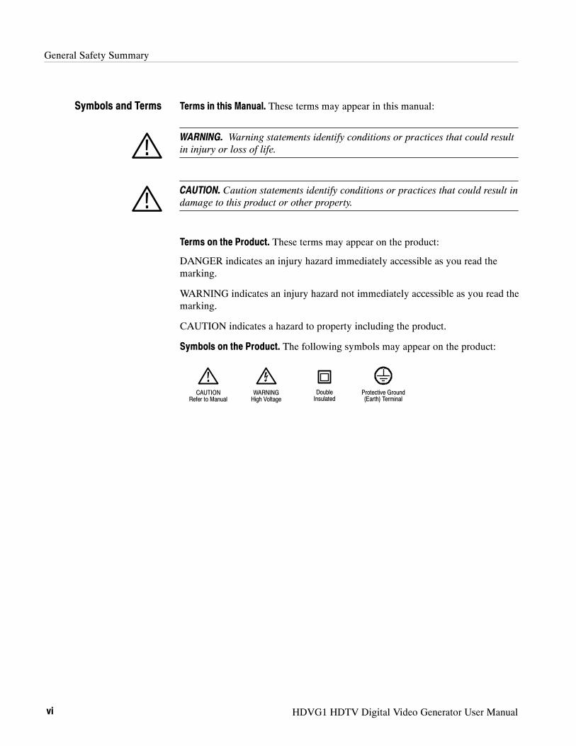
Terms in this Manual. These terms may appear in this manual:
WARNING. Warning statements identify conditions or practices that could resultin injury or loss of life.
CAUTION. Caution statements identify conditions or practices that could result indamage to this product or other property.
Terms on the Product. These terms may appear on the product:
DANGER indicates an injury hazard immediately accessible as you read themarking.
WARNING indicates an injury hazard not immediately accessible as you read themarking.
CAUTION indicates a hazard to property including the product.
Symbols on the Product. The following symbols may appear on the product:
CAUTIONRefer to Manual
WARNINGHigh Voltage
DoubleInsulated
Protective Ground(Earth) Terminal
Symbols and Terms
HDVG1 HDTV Digital Video Generator User Manual vii
Environmental Considerations
This section provides information about the environmental impact of theproduct.
Observe the following guidelines when recycling an instrument or component:
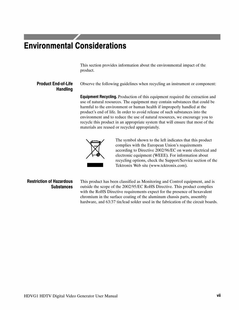
Equipment Recycling. Production of this equipment required the extraction anduse of natural resources. The equipment may contain substances that could beharmful to the environment or human health if improperly handled at theproduct’s end of life. In order to avoid release of such substances into theenvironment and to reduce the use of natural resources, we encourage you torecycle this product in an appropriate system that will ensure that most of thematerials are reused or recycled appropriately.
The symbol shown to the left indicates that this productcomplies with the European Union’s requirementsaccording to Directive 2002/96/EC on waste electrical andelectronic equipment (WEEE). For information aboutrecycling options, check the Support/Service section of theTektronix Web site (www.tektronix.com).
This product has been classified as Monitoring and Control equipment, and isoutside the scope of the 2002/95/EC RoHS Directive. This product complieswith the RoHS Directive requirements expect for the presence of hexavalentchromium in the surface coating of the aluminum chassis parts, assemblyhardware, and 63/37 tin/lead solder used in the fabrication of the circuit boards.
Product End-of-LifeHandling
Restriction of HazardousSubstances

Environmental Considerations
viii HDVG1 HDTV Digital Video Generator User Manual

HDVG1 HDTV Digital Video Generator User Manual ix
Preface
This manual documents the capabilities, specifications, operation, and installa-tion of the HDVG1 Generator module.
About This ManualThis manual is composed of the following sections:
H Getting Started contains product description, incoming inspection procedure,accessories list, and signal set installation procedure.
H Operating Basics tells how to control the HDVG1 Generator module throughthe windowed menu interface in conjunction with the front panel.
H Syntax and Commands defines the syntax used in command descriptions,list of all command subsystems, and describes all programming commands.
H Appendices provides additional information including the Specifications andhardware installation procedures.
Related ManualsThe following documents are also available.
H The HDVG1 HDTV Digital Video Generator Service Manual describes howto service the module. This optional manual must be ordered separately.
H The TG2000 Signal Generation Platform User Manual describes how to usethe TG2000 Platform. It also contains information about SCPI commands,programming structure, and atatus and events for the platform. Some of thisinformation applies to all generator modules, including the HDVG1Generator module. This manual is a standard accessary to the TG2000Platform mainframe.
H The TG2000 Signal Generation Platform Service Manual describes how toservice the mainframe to the module level and provides general informationabout servicing generator modules. This optional manual must be orderedseparately.
H A module user manual is included with each optional module. Contact yourTektronix Representative for list of the available generator and specialfunction modules.

Preface
x HDVG1 HDTV Digital Video Generator User Manual

Getting Started


HDVG1 HDTV Digital Video Generator User Manual 1- 1
Getting Started
This section contains the following information:
H Product description
H Accessories
H Option
H Functional Check
Product DescriptionThe HDVG1 HDTV Digital Video Generator module is designed to be installedin the TG2000 Signal Generation Platform. The TG2000 Platform must berunning version 2.0 or later firmware.
The module is an HDTV test signal generator which provides 1.485 Gb/s serialdigital video signals in various formats. The module contains the followingfeatures:
H Produces custom test signals using SDP2000 software package
H Three serial digital video outputs
H Signal parameters such as active video gain and chroma/luma gain areadjustable in real-time from the front panel.
H Rear-panel trigger output, used to trigger an oscilloscope or other videoequipment
H Overlay of circles, text, or logo on the video signal
H Up to 8 channels of Embedded Audio
H Full remote control using GPIB or RS-232C interface
Getting Started
1- 2 HDVG1 HDTV Digital Video Generator User Manual
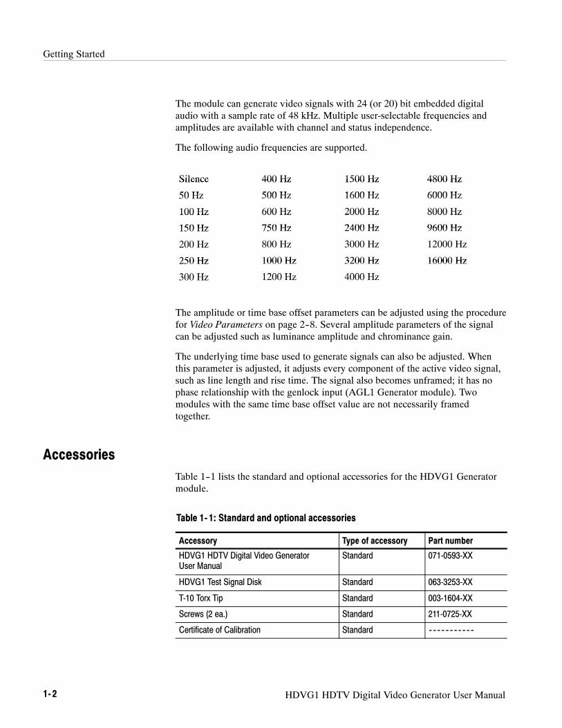
The module can generate video signals with 24 (or 20) bit embedded digitalaudio with a sample rate of 48 kHz. Multiple user-selectable frequencies andamplitudes are available with channel and status independence.
The following audio frequencies are supported.
Silence 400 Hz 1500 Hz 4800 HzSilence
50 H
400 Hz
500 H
1500 Hz
1600 H
4800 Hz
6000 H50 Hz 500 Hz 1600 Hz 6000 Hz
100 Hz 600 Hz 2000 Hz 8000 Hz100 Hz
150 Hz
600 Hz
750 Hz
2000 Hz
2400 Hz
8000 Hz
9600 Hz150 Hz 750 Hz 2400 Hz 9600 Hz
200 Hz 800 Hz 3000 Hz 12000 Hz
250 Hz 1000 Hz 3200 Hz 16000 Hz250 Hz
300 H
1000 Hz
1200 H
3200 Hz
4000 H
16000 Hz
300 Hz 1200 Hz 4000 Hz
The amplitude or time base offset parameters can be adjusted using the procedurefor Video Parameters on page 2--8. Several amplitude parameters of the signalcan be adjusted such as luminance amplitude and chrominance gain.
The underlying time base used to generate signals can also be adjusted. Whenthis parameter is adjusted, it adjusts every component of the active video signal,such as line length and rise time. The signal also becomes unframed; it has nophase relationship with the genlock input (AGL1 Generator module). Twomodules with the same time base offset value are not necessarily framedtogether.
AccessoriesTable 1--1 lists the standard and optional accessories for the HDVG1 Generatormodule.
Table 1- 1: Standard and optional accessories
Accessory Type of accessory Part number
HDVG1 HDTV Digital Video GeneratorUser Manual
Standard 071-0593-XX
HDVG1 Test Signal Disk Standard 063-3253-XX
T-10 Torx Tip Standard 003-1604-XX
Screws (2 ea.) Standard 211-0725-XX
Certificate of Calibration Standard ------ -- -- -- -- -- -- -- --

Getting Started
HDVG1 HDTV Digital Video Generator User Manual 1- 3
Table 1- 1: Standard and optional accessories (Cont.)
Accessory Part numberType of accessory
HDVG1 HDTV Digital Video GeneratorService Manual
Optional 071-0594-XX
Test Data Report Optional ---- -- -- -- -- -- -- -- -- --
OptionThis subsection describes the option available for the HDVG1 Generatormodule. The following option is available:
Option D1 (Test data report)
A calibration test data report will be provided with the HDVG1 Generatormodule when this option is specified.
Functional CheckThe following procedure determines whether the module is operating correctly. Ifyou are not familiar with the operation of the module, it may be helpful to referto Figure 2--1 on page 2--1 while performing these procedures.
For this procedure, you will need a digital television waveform monitor. Thisprocedure was created using the Tektronix WFM1125 Digital TelevisionWaveform Monitor.
1. Install the module into the TG2000 Platform mainframe using the installa-tion procedures beginning on page C--2.
2. Power on the TG2000 Signal Generation Platform. The platform runs a selftest on all modules.
3. To determine if the self test was successful, push theModule button. Checkthe display for the icon that represents the HDVG1 Generator module thatyou are inspecting.
4. Install signal sets into the module using the procedures on page C--6. Selectsignal formats that are compatible with your digital television waveformmonitor. (If another HDVG1 module is already installed, you do not need toinstall signal sets.)
Option D1 (Test DataReport)
Required Equipment
Procedure
Getting Started
1- 4 HDVG1 HDTV Digital Video Generator User Manual
5. Push the Modules button and touch the HDVG1 icon on the display.
6. Select a signal set and a test signal.
7. Connect Output 1 to the digital television waveform monitor.
8. Adjust the digital television waveform monitor to view the signal.
9. Check that the signal appears as expected. For example, if you selected acolor bar signal in step 6, check that the color bar signal appears.

Operating Basics


HDVG1 HDTV Digital Video Generator User Manual 2- 1
Functional Overview
This section provides an overview of the HDVG1 Generator module. If you arenot familiar with the operation of the TG2000 Signal Generation Platform, referto the TG2000 Signal Generation Platform User Manual before reading thissection.
Figure 2--1 shows the menu structure for basic module operations.
Edit Module window
Push Modulesbutton
Modules window
Signal Sets window
Touch desired signal set(usually represents format)
Push SignalSets button
Push TestSignals button
Active SignalParameters window
Touch desired Test Signal iconuntil correct signal is selected
Touch ModuleParameters
Touch ActiveSignal Parameters
Test Signals window
Touch desired module
Touch ModuleParameters
Touch RenameModule
Rename Module window
Enter new name formodule
Touch Video, Text Overlayor Signal Information
Video Parameters, Text Overlay,or Signal Information window
Set video parameters, adjust texton signal, or view informationabout the selected signal
Touch Output enable/disable, Module Timing,Circle Overlay, Trigger Output, Embedded Audio,
or Logo Overlay.
Module Timing, Circle Overlay, Trigger Output,Embedded Audio, or Logo Overlay window
Set module timing with respect to the BG1module. Create circle overlay or Logo Overlay.Configure trigger output, or embedded audio.
Module Parameters window
Push Editbutton
Figure 2- 1: Menu structure for the HDVG1 Generator module

Functional Overview
2- 2 HDVG1 HDTV Digital Video Generator User Manual
The HDVG1 Generator module has four outputs: three serial outputs and onetrigger output.
Serial Outputs. Outputs 1, 2 and 3 are serial signal outputs (BNC).
Trigger Output. The trigger output (BNC) can be used to trigger an oscilloscopeor other video equipment.
Push the front-panel HELP button to display a help window. The help windowdescribes the window you were using when you pushed HELP.
Outputs
Online Help
HDVG1 HDTV Digital Video Generator User Manual 2- 3
Operating Procedures
This section is organized into the following main topics:
H Power on the mainframe and select the module
H Select the output signal
H Active signal parameters
H Module parameters
Refer to Figure 2--1 on page 2--1 for the menu structure.
Operating Procedures
2- 4 HDVG1 HDTV Digital Video Generator User Manual
Power On and Select the ModuleAfter the module is installed in the mainframe, and the mainframe is installed inthe rack or other location where it will be used, power on the mainframe, andselect the module by following these steps:
1. Set the rear-panel power switch to the ON position.
2. Press the front-panel POWER switch if necessary.
3. Wait for a few seconds as the mainframe executes confidence tests on themainframe and modules. Check for any error messages that might appear.
4. When self tests are complete, the instrument displays icons representing thegenerator modules. If an installed module is not represented, refer toTroubleshooting in the HDVG1 HDTV Digital Video Generator ServiceManual.
NOTE. The illustrations in these procedures show the factory default name(HDVG1:X where X represents the slot number in which the module is installed).However, because you can rename the module, your icons may display a differentname. Refer to the TG2000 Signal Generation Platform User Manual forinformation about editing the module name.
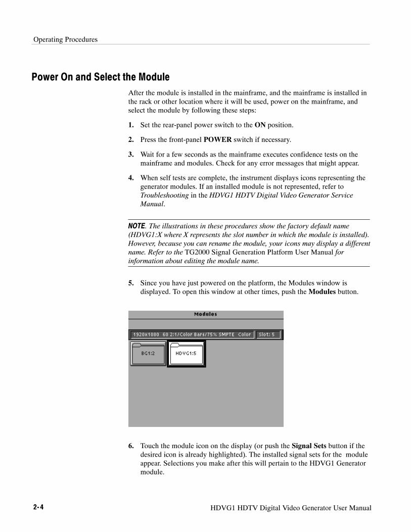
5. Since you have just powered on the platform, the Modules window isdisplayed. To open this window at other times, push theModules button.
6. Touch the module icon on the display (or push the Signal Sets button if thedesired icon is already highlighted). The installed signal sets for the moduleappear. Selections you make after this will pertain to the HDVG1 Generatormodule.
Operating Procedures
HDVG1 HDTV Digital Video Generator User Manual 2- 5
Select the Output SignalThe output signal is supplied on the three rear-panel serial outputs. Use thefollowing procedure to select the module’s output test signal. You can select anyof the HDVG1 signals that are loaded in your instrument.
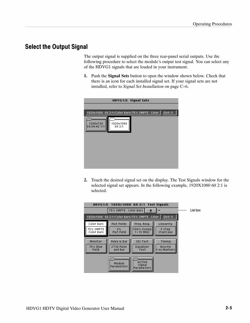
1. Push the Signal Sets button to open the window shown below. Check thatthere is an icon for each installed signal set. If your signal sets are notinstalled, refer to Signal Set Installation on page C--6.
2. Touch the desired signal set on the display. The Test Signals window for theselected signal set appears. In the following example, 1920X1080 60 2:1 isselected.
List box
Operating Procedures
2- 6 HDVG1 HDTV Digital Video Generator User Manual
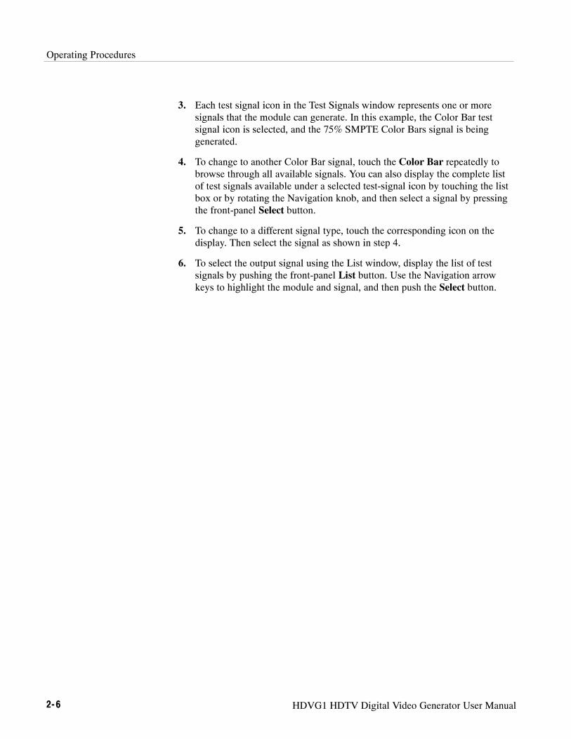
3. Each test signal icon in the Test Signals window represents one or moresignals that the module can generate. In this example, the Color Bar testsignal icon is selected, and the 75% SMPTE Color Bars signal is beinggenerated.
4. To change to another Color Bar signal, touch the Color Bar repeatedly tobrowse through all available signals. You can also display the complete listof test signals available under a selected test-signal icon by touching the listbox or by rotating the Navigation knob, and then select a signal by pressingthe front-panel Select button.
5. To change to a different signal type, touch the corresponding icon on thedisplay. Then select the signal as shown in step 4.
6. To select the output signal using the List window, display the list of testsignals by pushing the front-panel List button. Use the Navigation arrowkeys to highlight the module and signal, and then push the Select button.

Operating Procedures
HDVG1 HDTV Digital Video Generator User Manual 2- 7
Active Signal ParametersThe following procedures discuss windows that are accessed through the ActiveSignal Parameters window, shown below. Changes that you make to parametersin any of these windows affect only the active signal.
To enter the Active Signal Parameters window for the HDVG1 Generatormodule, follow these steps:
1. Select the module, if not already selected.
2. Push the Test Signals button.
3. Touch Active Signal Parameters at the bottom of the screen. The ActiveSignal Parameters window appears, as shown below.
Operating Procedures
2- 8 HDVG1 HDTV Digital Video Generator User Manual
You can adjust the signal parameters of the currently selected (active) test signalby modifying the parameters and then saving the signal with a new name. Thereare no factory defaults. Factory signals may be re--installed, if needed.
NOTE. To modify and save a Tektronix generated signal, you must rename it.When you rename and save a signal, both the original and the modified signalsare saved.
To change the signal parameters, follow these steps:
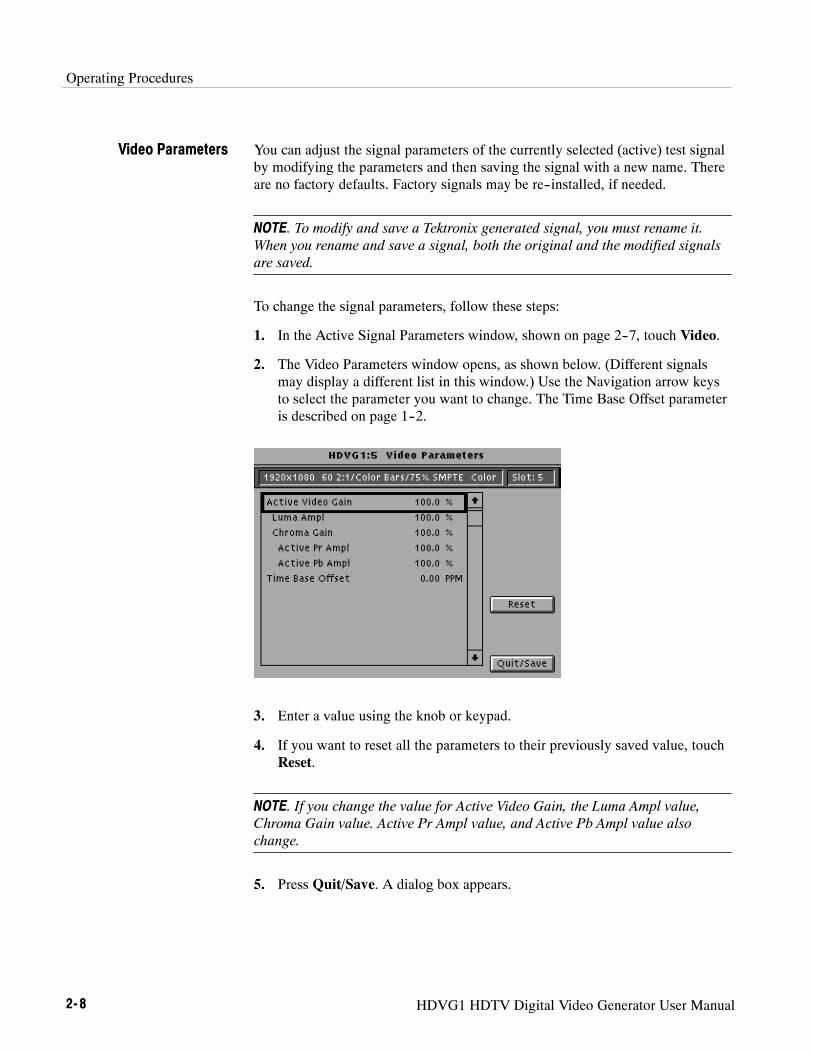
1. In the Active Signal Parameters window, shown on page 2--7, touch Video.
2. The Video Parameters window opens, as shown below. (Different signalsmay display a different list in this window.) Use the Navigation arrow keysto select the parameter you want to change. The Time Base Offset parameteris described on page 1--2.
3. Enter a value using the knob or keypad.
4. If you want to reset all the parameters to their previously saved value, touchReset.
NOTE. If you change the value for Active Video Gain, the Luma Ampl value,Chroma Gain value. Active Pr Ampl value, and Active Pb Ampl value alsochange.
5. Press Quit/Save. A dialog box appears.
Video Parameters

Operating Procedures
HDVG1 HDTV Digital Video Generator User Manual 2- 9
NOTE. If you modify any signal that was shipped on the factory disks, theplatform adds an underscore to the front of the name.
6. Touch Save As to save and rename the test signal. A text entry windowappears as shown in the following illustration. The platform suggests a newtest signal name for you by adding an underscore to the front of the currentname.
7. To use the suggested name, touch OK.
8. If you want a different name, do the following:
a. Delete the displayed name using the BS key, and then enter new text.(You cannot backspace over an underscore character.)
b. Touch Set1 or Set2 to provide additional sets of characters.
c. Touch OK when text is complete.
9. Touch Quit/Save to exit the window.

Operating Procedures
2- 10 HDVG1 HDTV Digital Video Generator User Manual
You can enter text that overlays your displayed test signal. When turning text onor off, you are turning text on or off for all test signals that have overlaid text,even though the text may be different for each signal. Touching Reset returns thetext, horizontal and vertical to previously saved values.
To enter and position text, follow these steps:
1. In the Active Signal Parameters window, shown on page 2--7, touch TextOverlay to enter the Signal Text window. The Signal Text window is shownin the following illustration.
2. Touch Edit Text to enter the text entry window as shown in the followingillustration.
Text Overlay

Operating Procedures
HDVG1 HDTV Digital Video Generator User Manual 2- 11
3. Enter text as follows:
a. Touch the desired letters on the display.
b. Touch Return if you want to enter a new line.
c. Touch the list box at the top of the window to see all the text entered.
d. Touch OK when text entry is complete. The Signal Text Overlay menureturns.
4. Touch Text On/Off to display the text on your monitor. The Signal TextOverlay menu lists the text you previously entered, as shown in thefollowing illustration.
5. Touch H Pos.
6. Enter a value from the keypad or rotate the knob until the desired horizontalposition is reached.
7. Touch V Pos.
8. Enter a value from the keypad or rotate the knob until the desired horizontalposition is reached.
9. If you want to return the text, horizontal and vertical to previously savedvalue, touch Reset.
10. Touch Quit/Save. A dialog box appears.
a. If you touch Save, the modified test signal is saved with an underscoreadded to the front of the name.
b. If you touch Save As, a text entry window is displayed. Enter a newname for the signal.
Operating Procedures
2- 12 HDVG1 HDTV Digital Video Generator User Manual
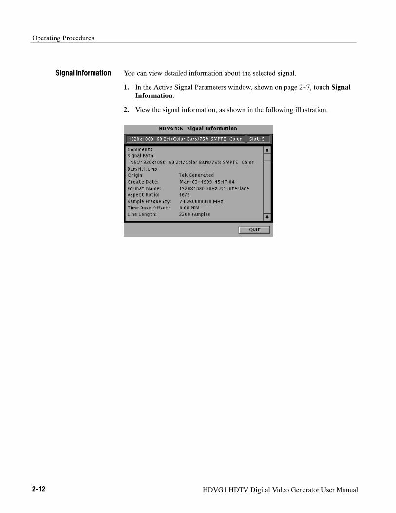
You can view detailed information about the selected signal.
1. In the Active Signal Parameters window, shown on page 2--7, touch SignalInformation.
2. View the signal information, as shown in the following illustration.
Signal Information

Operating Procedures
HDVG1 HDTV Digital Video Generator User Manual 2- 13
Module ParametersThe following procedures discuss windows that are accessed through the ModuleParameters window, shown below. Changes that you make to parameters in anyof these windows affect the entire module.
To enter the Module Parameters window for the HDVG1 Generator module,follow these steps:
1. Select the HDVG1 Generator module, if not already selected.
2. Push the Test Signals button.
3. TouchModule Parameters at the bottom of the screen. The ModuleParameters window appears, as shown below.
4. Another way to access this window is as follows:
a. Push theModules button.
b. Ensure that the module is highlighted.
c. Push the Edit button.
d. TouchModule Parameters.

Operating Procedures
2- 14 HDVG1 HDTV Digital Video Generator User Manual
You can create a circle that is overlaid on the output test signal. The circleoverlay parameters will affect all test signals from this module. Entered valuesare constant, regardless of which test signal or video standard you use.
To define a circle overlay, follow these steps:
1. In the Module Parameters window, shown on page 2--13, touch CircleOverlay to enter the Circle Overlay window. The Circle Overlay window isshown in the following illustration.
2. Touch On/Off to turn on the circle overlay.
3. Touch Diam.
4. Touch the Navigation knob or enter a value from the keypad. Rotating theknob changes the diameter by percentages of Active Picture Height (APH).
5. Touch H Pos and rotate the Navigation knob to move the circle horizontallyby a percentage of APH.
6. Touch V Pos and rotate the Navigation knob to move the circle horizontallyby a percentage of APH.
7. If you want to reset the values, touch Reset All. This will set the diameter,horizontal, and vertical to 90%, 0, and 0 respectively.
8. Touch Quit to exit the window.
If you disable the module output, it releases all system resources used by thismodule. To disable the module output, follow these steps:
1. Select the module, if not already selected.
2. Push the Test Signals button.
Circle Overlay
Enable/Disable theOutput Signal

Operating Procedures
HDVG1 HDTV Digital Video Generator User Manual 2- 15
3. TouchModule Parameters at the bottom of the screen. The ModuleParameters window (shown on page 2--13) appears.
4. Touch the Output icon to toggle the state of the module’s output signal.
5. Touch Quit to exit.
You can turn embedded audio on or off, select which channel groups to enable,and which of the enabled groups to send first. You can also adjust the frequencyand amplitude of the embedded audio signal. Changes you make affect allsignals for this module.
1. In the Module Parameters window, shown on page 2--13, touch EmbeddedAudio to enter the Embedded Audio window shown below.
2. To enable the embedded audio, perform the following steps:
a. Touch the Audio icon to turn on the embedded audio.
b. Touch the Number of Groups Enabled list box and use the navigationarrow to select the number of groups you want to enable (1 or 2).
c. Push the Select button.
d. Touch the Starting Group list box and use the navigation arrow toselect the group that will be sent first.
e. Push the Select button.
3. To configure the channel parameters, perform the following steps:
a. Touch the icon corresponding to the group that you want to configure.The Audio Groups window will appear. The following illustration showsan audio group window for Audio Group 1 or 3.
Embedded Audio

Operating Procedures
2- 16 HDVG1 HDTV Digital Video Generator User Manual
b. Touch the list box corresponding to the channel for which you want tochange the frequency. A list window appears for you to select the desiredfrequency.
c. Select the desired frequency using the cursor keys and the Select button.
d. Perform steps b and c for each channel you want to adjust.
e. To change the amplitude, touch Ampl: next to the desired channel andenter a value using the keypad. Selections range from --60 to 0 decibelsfull scale (dBFS).
f. To change the sampling alignment status bit in the embedded audiostream, touch Sampling icon until the desired selection Async (asynch-ronous), Sync w/o Frame #s (synchronous without frame numbers), orSync with Frame #s (Synchronous with frame numbers) is displayed.
g. To change the sample bits, touch Resolution icon until the desiredselection 20 bits or 24 bits is displayed.
h. To change the Preemphasis status bit in the embedded audio stream,touch the Preemphasis icon until the desired selection Off, CD, orCCITT is displayed.
You can provide a logo that is overlaid on the output test signal. The logooverlay parameters will affect all test signals from this module. Entered valuesare constant, regardless of which test signal or video standard you use.
To define a logo overlay, follow these steps:
1. In the Module Parameters window, shown on page 2--13, touch LogoOverlay to enter the Logo Overlay window. The Logo Overlay window isshown in the following illustration.
Logo Overlay

Operating Procedures
HDVG1 HDTV Digital Video Generator User Manual 2- 17
2. Touch On/Off to turn on the logo overlay.
3. Touch the Select Logo list box and use the Navigation arrows to select thelogo file you want to use.
4. If the file you want to use does not appear in the list, you can add the logofile to the list using Add Logo from Disk function. Refer to Add Logo fromDisk on page 2--20 .
5. Touch H Pos and rotate the Navigation knob to move the logo horizontallyby a percentage of APH.
6. Touch V Pos and rotate the Navigation knob to move the logo vertically by apercentage of APH.
7. If you want to reset the values touch Reset. This will set the horizontal andvertical to 0.
8. Touch Quit to exit the window.

Operating Procedures
2- 18 HDVG1 HDTV Digital Video Generator User Manual
You can save logos to a disk, add logos from a disk, and delete logos from themodule using the Logo File Utilities window.
To enter the Logo File Utilities window, touch File Utils in the Logo Overlaywindow, shown on page 2--17. The Logo File Utilities window is shown in thefollowing illustration.
Save Logo to Disk. From the Save Logo to Disk window you can save logos to adisk. You should save all logos in the module to disk before removing themodule. Modules loose their memory after 30 seconds out of the mainframe.
To save logos to a disk, follow these steps:
1. In the Logo File Utilities window shown above, touch Save Logo to Disk toenter the Save Logo to Disk window. The Save Logo to Disk window isshown in the following illustration.
Logo File Utilities

Operating Procedures
HDVG1 HDTV Digital Video Generator User Manual 2- 19
2. Insert a preformatted floppy disk into the drive. Ensure that the disk is notwrite protected.
3. Touch Select Source. The Save Logo to Disk--Select Source windowappears, as shown below.
4. Select the logos you want to save to a disk file.
5. Touch Quit/Save to exit the window.
6. In the Save Logo to Disk window, shown on page 2--18, touch SelectDestination. The Save Logo to Disk--Select Destination window appears, asshown below.
Operating Procedures
2- 20 HDVG1 HDTV Digital Video Generator User Manual
7. Use the New Dir selection to create a directory on the disk if you like.Otherwise select New File and give the logo file a name.
8. With the Source and Destination entered you are ready to save the logos tothe disk. Touch Quit/Save to begin the save process.
Saving a logo to disk takes a brief time depending on the size of the logofile.
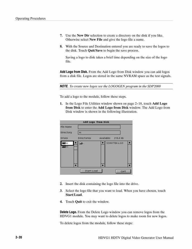
Add Logo from Disk. From the Add Logo from Disk window you can add logosfrom a disk file. Logos are stored in the same NVRAM space as the test signals.
NOTE. To create new logos see the LOGOGEN program in the SDP2000
To add a logo to the module, follow these steps.
1. In the Logo File Utilities window shown on page 2--18, touch Add Logofrom Disk to enter the Add Logo from Disk window. The Add Logo fromDisk window is shown in the following illustration.
2. Insert the disk containing the logo file into the drive.
3. Select the logo file that you want to load. When you have chosen, touchStart/Load.
4. Touch Quit to exit the window.
Delete Logo. From the Delete Logo window you can remove logos from theHDVG1 module. You may want to delete logos to make room for new logos.
To delete logos from the module, follow these steps:

Operating Procedures
HDVG1 HDTV Digital Video Generator User Manual 2- 21
1. In the Logo File Utilities window shown on page 2--18, touch Delete Logoto enter the Delete Logo window. The Delete Logo window is shown in thefollowing illustration.
2. Select the logo you wish to delete.
3. Touch the Delete to remove the selected logo from the module.
4. Touch Quit to exit the window.
You can set the horizontal and vertical timing of this module with respect to theBG1 Generator module, when they are running at the same frame rate. Changesyou make to timing affect all signals for the HDVG1 Generator module as wellas the relative timing between the HDVG1 and BG1 Generator modules.
NOTE. Time zero is when the HDVG1 Generator module timing is the same asthe BG1 Generator module, and they are running at the same frame rate
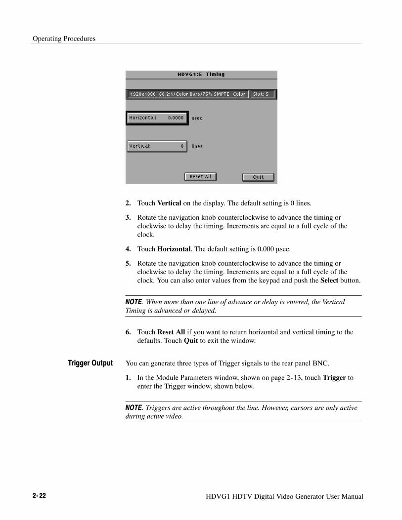
1. In the Module Parameters window, shown on page 2--13, touch the moduletiming icon. The Timing window appears, as shown in the followingillustration.
Timing
Operating Procedures
2- 22 HDVG1 HDTV Digital Video Generator User Manual
2. Touch Vertical on the display. The default setting is 0 lines.
3. Rotate the navigation knob counterclockwise to advance the timing orclockwise to delay the timing. Increments are equal to a full cycle of theclock.
4. Touch Horizontal. The default setting is 0.000 msec.
5. Rotate the navigation knob counterclockwise to advance the timing orclockwise to delay the timing. Increments are equal to a full cycle of theclock. You can also enter values from the keypad and push the Select button.
NOTE. When more than one line of advance or delay is entered, the VerticalTiming is advanced or delayed.
6. Touch Reset All if you want to return horizontal and vertical timing to thedefaults. Touch Quit to exit the window.
You can generate three types of Trigger signals to the rear panel BNC.
1. In the Module Parameters window, shown on page 2--13, touch Trigger toenter the Trigger window, shown below.
NOTE. Triggers are active throughout the line. However, cursors are only activeduring active video.
Trigger Output

Operating Procedures
HDVG1 HDTV Digital Video Generator User Manual 2- 23
2. Turn on the cursor by touching the On/Off on the display. A cursor providesline and pixel selection anywhere within the frame.
3. Touch Type on the display until the desired type of trigger is displayed:
H Horizontal (one trigger pulse per line at location entered)
H Vertical (one trigger pulse per color frame at beginning of line entered)
H Pixel (one trigger pulse per color frame at intersection of horizontal andvertical trigger)
4. If the type is horizontal or pixel, touch HPos us (to adjust horizontalposition by time) or HPos samples (to adjust horizontal position bysamples). Rotate the Navigation knob until the desired position is reached,or enter a value using the keypad and push enter.
5. If the type is vertical or pixel, touch VPos and rotate the Navigation knobuntil the desired line is reached. You can also enter a value using the keypad.
6. Touch Reset All if you want to set all the parameters to the default settings(H Pos to zero and V Pos to 1).
7. Touch Quit to exit the window.

Operating Procedures
2- 24 HDVG1 HDTV Digital Video Generator User Manual

Syntax and Commands

HDVG1 HDTV Digital Video Generator User Manual 3- 1
Syntax
This section contains information on the Standard Commands for ProgrammableInstruments (SCPI) and the programming structure you can use to program yourHDVG1 Generator module.
Programming ModelSpecific conditions must exist before programming commands will affect the testsignal generated by a module.
The following two steps must be performed before the test module will respondto signal parameter commands.
1. Select the module using the :INSTrument:SELect command before executingany commands. Many of the commands used by the HDVG1 module areshared by several modules and will be accepted without a reported error.
2. Enable the module using the :OUTPut:STATe ON command. The outputstate of the module must be enabled before test signal parameters can bechanged.
Many commands will accept either string or numeric arguments. For example: aboolean argument can either be “1” or “ON“.
Signal parameter commands that have a :STEP node can accept either a numericvalue or they can accept a string argument that refers to the :STEP increment.
Signal parameter commands with a :STEP node will accept the following stringsin addition to a numeric value:
UP.Use this argument to increase the parameter value one increment as definedby the :STEP value.
DOWN.Use this argument to decrease the parameter value one increment asdefined by the :STEP value.
Addressing Module TestSignals
Command Arguments

Syntax
3- 2 HDVG1 HDTV Digital Video Generator User Manual
MINimum.Use this argument to set the parameter value to the minimumacceptable value.
MAXimum.Use this argument to set the parameter value to the maximumacceptable value.
DEFault.Use this argument to set the parameter value to the default value.
If you send a query with no argument, the response is the current value.You can also use MINimum, MAXimum, and DEFault as arguments for querieswhose command form can use these arguments (refer to the command syntax forthe specific command). Instead of returning the current value, queries using thesearguments return the following information:
MINimum. Return the minimum acceptable value.
MAXimum. Return the maximum acceptable value.
DEFault. Return the default value.
The following example demonstrates the effect of each of the arguments whenused with a step value.
1. :INSTrument:SELect ”HDVG1:#” selects the digital video generator modulelocated in the slot number indicated by the “#” symbol.
2. :OUTPut:STATe ON enables the module and displays the loaded test signal.
3. :OUTPut:CIRCle:STATe ON displays a circle on the video display.
NOTE. :OUTPut:CIRCle:DIAMeter uses an argument that is the percent ofpicture height.
4. :OUTPut:CIRCle:DIAMeter DEFault sets the circle diameter to 90 percentof the screen height.
5. :OUTPut:CIRCle:DIAMeter:STEP 10 sets the step increment to 10 percent.
6. :OUTPut:CIRCle:DIAMeter DOWN changes the circle diameter to80 percent of the screen height.
7. :OUTPut:CIRCle:DIAMeter 50 changes the circle diameter to 50 percent ofthe screen height.
Query Arguments
Argument Example

Syntax
HDVG1 HDTV Digital Video Generator User Manual 3- 3
8. :OUTPut:CIRCle:DIAMeter MAXimum changes the circle diameter to100 percent of the screen height.
9. :OUTPut:CIRCle:DIAMeter MINimum changes the circle diameter to0 percent of the screen height.
10. :OUTPut:CIRCle:DIAMeter UP changes the circle diameter to 10 percent ofthe screen height.
11. :OUTPut:CIRCle:DIAMeter? MAXimum queries the maximum circlediameter (not the current diameter). The query returns the value of 100percent, which is the maximum circle diameter allowable.

Syntax
3- 4 HDVG1 HDTV Digital Video Generator User Manual
SCPI Commands and QueriesSCPI is a standard created by a consortium that provides guidelines for remoteprogramming of instruments. These guidelines provide a consistent program-ming environment for instrument control and data transfer. This environmentuses defined programming messages, instrument responses, and data formatacross all SCPI instruments, regardless of manufacturer. The HDVG1 Generatormodule uses a command language based on the SCPI standard.
The SCPI language is based on a hierarchical or tree structure (see Figure 3--1)that represents a subsystem. The top level of the tree is the root node; it isfollowed by one or more lower-level nodes.
DIAMeter
OUTPut
CIRCle
POSitionSTATe
Root node
Lower-levelnodes
Figure 3- 1: Example of SCPI subsystem hierarchy
You can create commands and queries from these subsystem hierarchy trees.Commands specify actions for the instrument to perform. Queries returnmeasurement data and information about parameter settings.
For more information on SCPI commands, programming structure, and TG2000Signal Generation Platform status and events, refer to the TG2000 SignalGeneration Platform User Manual.
HDVG1 HDTV Digital Video Generator User Manual 3- 5
Functional Command Groups
This section describes the commands in general categories. Commands to themodule are divided into the following groups:
H MMEMory (see TG2000 Signal Generation Platform User Manual)
H OUTPut
H SENSe
H SOURce
Items followed by question marks are queries; items without question marks arecommands. Some items in this section have a question mark in parentheses (?) inthe command header section; this indicates that the item can be both a commandand a query.
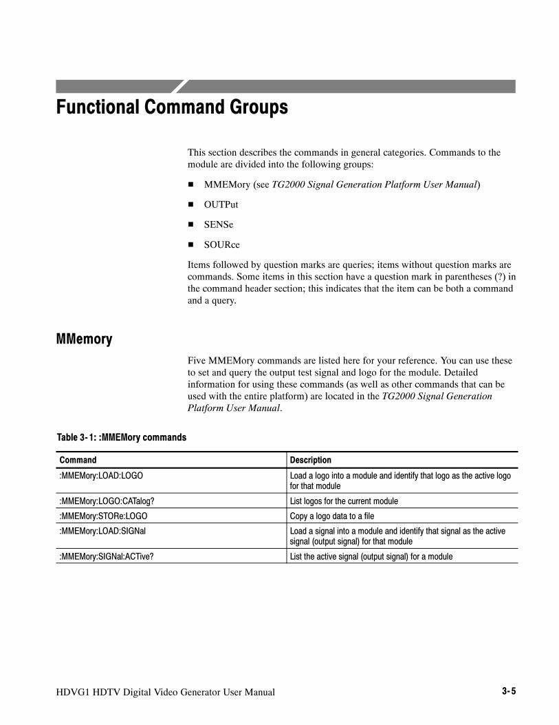
MMemoryFive MMEMory commands are listed here for your reference. You can use theseto set and query the output test signal and logo for the module. Detailedinformation for using these commands (as well as other commands that can beused with the entire platform) are located in the TG2000 Signal GenerationPlatform User Manual.
Table 3- 1: :MMEMory commands
Command Description
:MMEMory:LOAD:LOGO Load a logo into a module and identify that logo as the active logofor that module
:MMEMory:LOGO:CATalog? List logos for the current module
:MMEMory:STORe:LOGO Copy a logo data to a file
:MMEMory:LOAD:SIGNal Load a signal into a module and identify that signal as the activesignal (output signal) for that module
:MMEMory:SIGNal:ACTive? List the active signal (output signal) for a module
Functional Command Groups
3- 6 HDVG1 HDTV Digital Video Generator User Manual
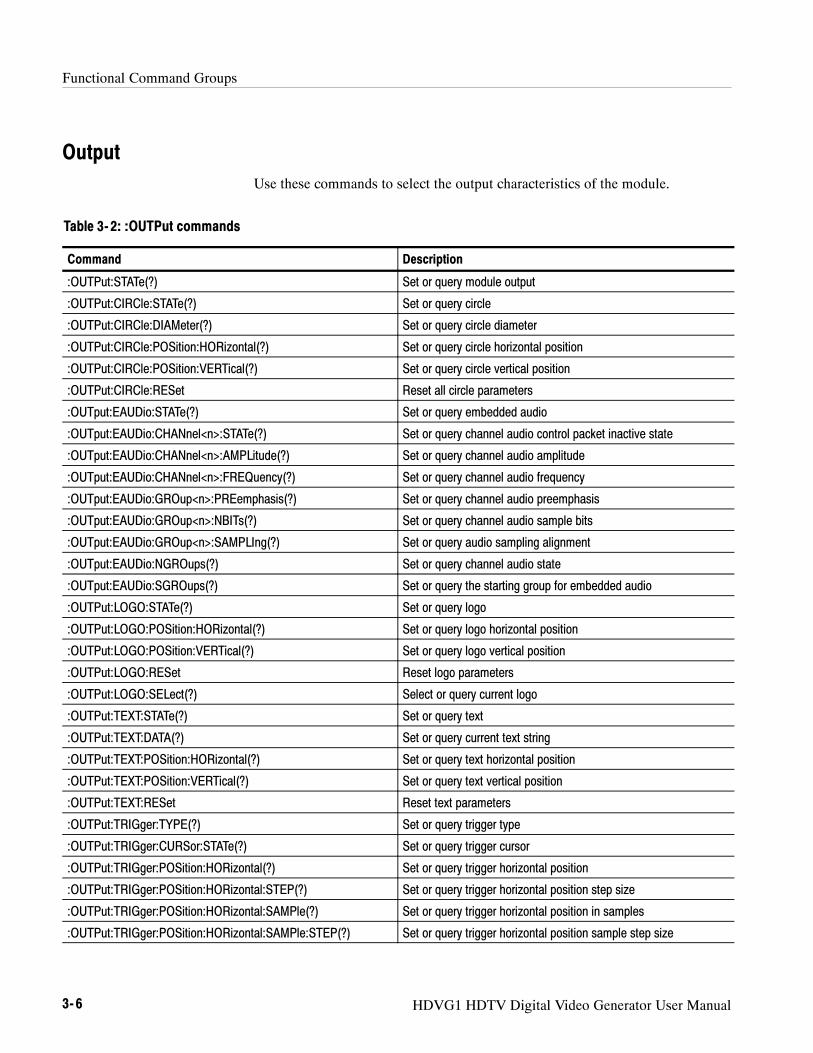
OutputUse these commands to select the output characteristics of the module.
Table 3- 2: :OUTPut commands
Command Description
:OUTPut:STATe(?) Set or query module output
:OUTPut:CIRCle:STATe(?) Set or query circle
:OUTPut:CIRCle:DIAMeter(?) Set or query circle diameter
:OUTPut:CIRCle:POSition:HORizontal(?) Set or query circle horizontal position
:OUTPut:CIRCle:POSition:VERTical(?) Set or query circle vertical position
:OUTPut:CIRCle:RESet Reset all circle parameters
:OUTput:EAUDio:STATe(?) Set or query embedded audio
:OUTput:EAUDio:CHANnel<n>:STATe(?) Set or query channel audio control packet inactive state
:OUTput:EAUDio:CHANnel<n>:AMPLitude(?) Set or query channel audio amplitude
:OUTput:EAUDio:CHANnel<n>:FREQuency(?) Set or query channel audio frequency
:OUTput:EAUDio:GROup<n>:PREemphasis(?) Set or query channel audio preemphasis
:OUTput:EAUDio:GROup<n>:NBITs(?) Set or query channel audio sample bits
:OUTput:EAUDio:GROup<n>:SAMPLIng(?) Set or query audio sampling alignment
:OUTput:EAUDio:NGROups(?) Set or query channel audio state
:OUTput:EAUDio:SGROups(?) Set or query the starting group for embedded audio
:OUTPut:LOGO:STATe(?) Set or query logo
:OUTPut:LOGO:POSition:HORizontal(?) Set or query logo horizontal position
:OUTPut:LOGO:POSition:VERTical(?) Set or query logo vertical position
:OUTPut:LOGO:RESet Reset logo parameters
:OUTPut:LOGO:SELect(?) Select or query current logo
:OUTPut:TEXT:STATe(?) Set or query text
:OUTPut:TEXT:DATA(?) Set or query current text string
:OUTPut:TEXT:POSition:HORizontal(?) Set or query text horizontal position
:OUTPut:TEXT:POSition:VERTical(?) Set or query text vertical position
:OUTPut:TEXT:RESet Reset text parameters
:OUTPut:TRIGger:TYPE(?) Set or query trigger type
:OUTPut:TRIGger:CURSor:STATe(?) Set or query trigger cursor
:OUTPut:TRIGger:POSition:HORizontal(?) Set or query trigger horizontal position
:OUTPut:TRIGger:POSition:HORizontal:STEP(?) Set or query trigger horizontal position step size
:OUTPut:TRIGger:POSition:HORizontal:SAMPle(?) Set or query trigger horizontal position in samples
:OUTPut:TRIGger:POSition:HORizontal:SAMPle:STEP(?) Set or query trigger horizontal position sample step size
Functional Command Groups
HDVG1 HDTV Digital Video Generator User Manual 3- 7
Table 3- 2: :OUTPut commands (Cont.)
Command Description
:OUTPut:TRIGger:POSition:VERTical(?) Set or query trigger vertical position
:OUTPut:TRIGger:POSition:VERTical:STEP(?) Set or query trigger vertical position step size
:OUTPut:TRIGger:RESet Reset trigger parameters
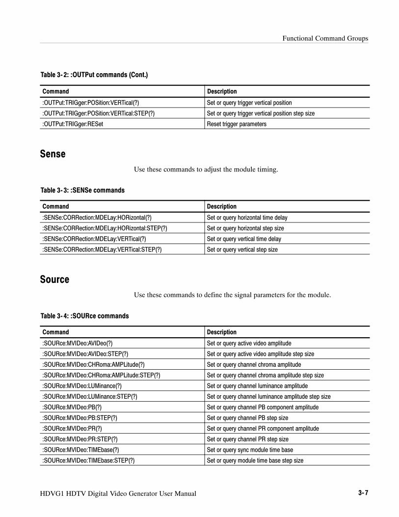
SenseUse these commands to adjust the module timing.
Table 3- 3: :SENSe commands
Command Description
:SENSe:CORRection:MDELay:HORizontal(?) Set or query horizontal time delay
:SENSe:CORRection:MDELay:HORizontal:STEP(?) Set or query horizontal step size
:SENSe:CORRection:MDELay:VERTical(?) Set or query vertical time delay
:SENSe:CORRection:MDELay:VERTical:STEP(?) Set or query vertical step size
SourceUse these commands to define the signal parameters for the module.
Table 3- 4: :SOURce commands
Command Description
:SOURce:MVIDeo:AVIDeo(?) Set or query active video amplitude
:SOURce:MVIDeo:AVIDeo:STEP(?) Set or query active video amplitude step size
:SOURce:MVIDeo:CHRoma:AMPLitude(?) Set or query channel chroma amplitude
:SOURce:MVIDeo:CHRoma:AMPLitude:STEP(?) Set or query channel chroma amplitude step size
:SOURce:MVIDeo:LUMinance(?) Set or query channel luminance amplitude
:SOURce:MVIDeo:LUMinance:STEP(?) Set or query channel luminance amplitude step size
:SOURce:MVIDeo:PB(?) Set or query channel PB component amplitude
:SOURce:MVIDeo:PB:STEP(?) Set or query channel PB step size
:SOURce:MVIDeo:PR(?) Set or query channel PR component amplitude
:SOURce:MVIDeo:PR:STEP(?) Set or query channel PR step size
:SOURce:MVIDeo:TIMEbase(?) Set or query sync module time base
:SOURce:MVIDeo:TIMEbase:STEP(?) Set or query module time base step size
Functional Command Groups
3- 8 HDVG1 HDTV Digital Video Generator User Manual
HDVG1 HDTV Digital Video Generator User Manual 3- 9
:OUTPut Commands
Use these commands to enable the actual output of the module. This subsystemalso controls the embedded audio, circle overlay, logo overlay, and moduletrigger.
NOTE. The module must be selected with the INSTrument:SELect command priorto using these commands.

:OUTPut Commands
3- 10 HDVG1 HDTV Digital Video Generator User Manual
Command Tree:OUTPut
:STATe <boolean>:CIRCle
:STATe <boolean>:DIAMeter <numeric_value>:POSition
:HORizontal <numeric_value>:VERTical <numeric_value>
:RESet:EAUDio
:STATe <boolean>:CHANnel<n>
:STATe <boolean>:AMPLitude <numeric_value>:FREQuency <numeric_value>
:GROup<n>:PREemphasis <argument>:NBITs <numeric_value>:SAMPLIng <argument>
:NGRoups <numeric_value>:SGRoup <numeric_value>
:LOGO:STATe <boolean>:POSition
:HORizontal <numeric_value>:VERTical <numeric_value>
:RESet:SELect <string>
:TEXT:STATe <boolean>:DATA <string>:POSition
:HORizontal <numeric_value>:VERTical <numeric_value>
:RESet:TRIGer
:TYPE <argument>:CURSor
:STATe <boolean>:POSition
:VERTical <numeric_value>:STEP <numeric_value>
:HORizontal <numeric_value>:STEP <numeric_value>
:RESet

:OUTPut Commands
HDVG1 HDTV Digital Video Generator User Manual 3- 11
:OUTPut:STATe(?)Use this command to set or query the state of the HDVG1 Generator moduleoutput signal.
:OUTPut:STATe <boolean>:OUTPut:STATe?
Command Query response
<boolean> = ON or 1, OFF or 0 1, 0
ON
None
None
Command: :OUTP:STAT ON
Query: :OUTP:STAT?
Response: 1
None
Syntax
Parameters
Default Value
Errors and Events
Dependencies
Examples
Related Commands
:OUTPut Commands
3- 12 HDVG1 HDTV Digital Video Generator User Manual
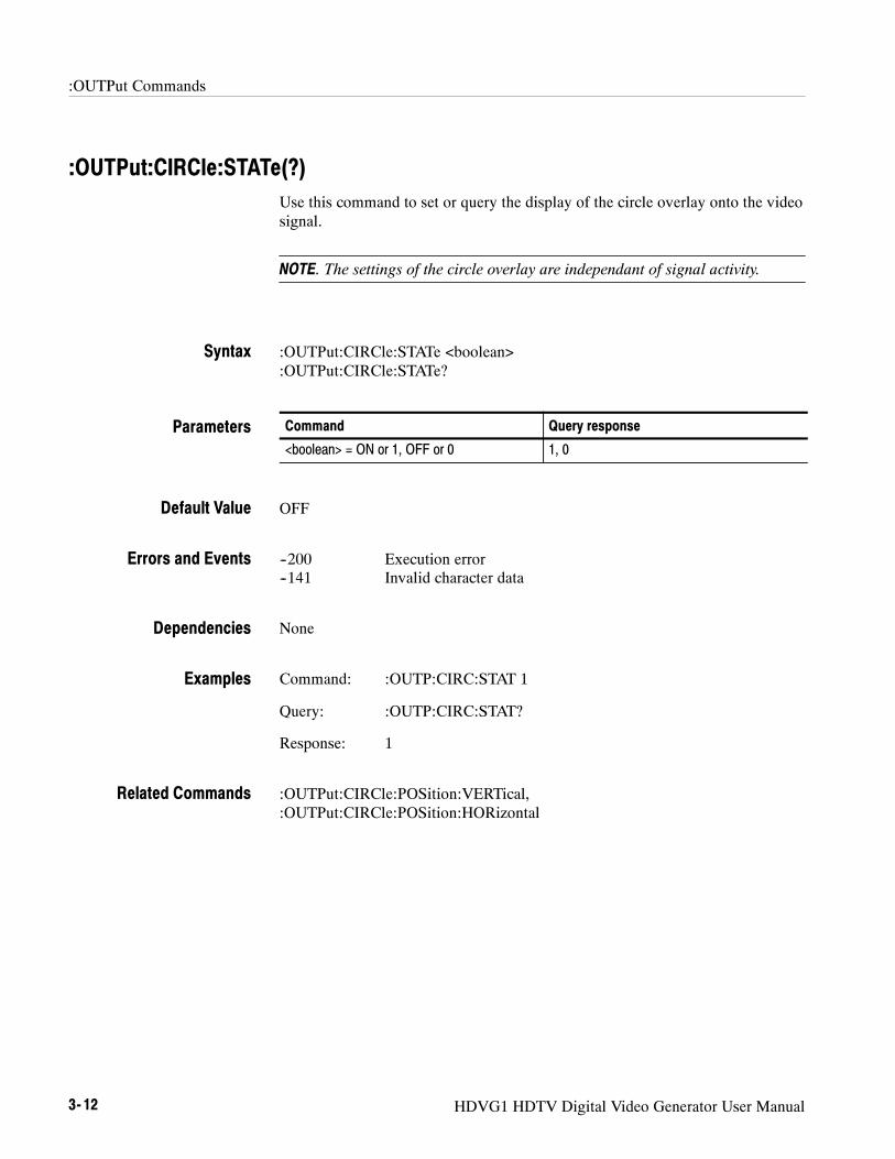
:OUTPut:CIRCle:STATe(?)Use this command to set or query the display of the circle overlay onto the videosignal.
NOTE. The settings of the circle overlay are independant of signal activity.
:OUTPut:CIRCle:STATe <boolean>:OUTPut:CIRCle:STATe?
Command Query response
<boolean> = ON or 1, OFF or 0 1, 0
OFF
--200 Execution error--141 Invalid character data
None
Command: :OUTP:CIRC:STAT 1
Query: :OUTP:CIRC:STAT?
Response: 1
:OUTPut:CIRCle:POSition:VERTical,:OUTPut:CIRCle:POSition:HORizontal
Syntax
Parameters
Default Value
Errors and Events
Dependencies
Examples
Related Commands

:OUTPut Commands
HDVG1 HDTV Digital Video Generator User Manual 3- 13
:OUTPut:CIRCle:DIAMeter(?)Use this command to set or query the diameter of the displayed circle. The unitis percent of average picture height.
:OUTPut:CIRCle:DIAMeter <numeric_value>:OUTPut:CIRCle:DIAMeter?
Command Query response
<numeric_value> = <NRf>
MIN, MAX, DEF
<NR2>
90
--200 Execution error--120 Numeric data error
None
Command: :OUTP:CIRC:DIAM 75
Query: :OUTP:CIRC:DIAM?
Response: 75.0000
:OUTPut:CIRCle:POSition:VERTical,:OUTPut:CIRCle:POSition:HORizontal
Syntax
Parameters
Default Value
Errors and Events
Dependencies
Examples
Related Commands
:OUTPut Commands
3- 14 HDVG1 HDTV Digital Video Generator User Manual
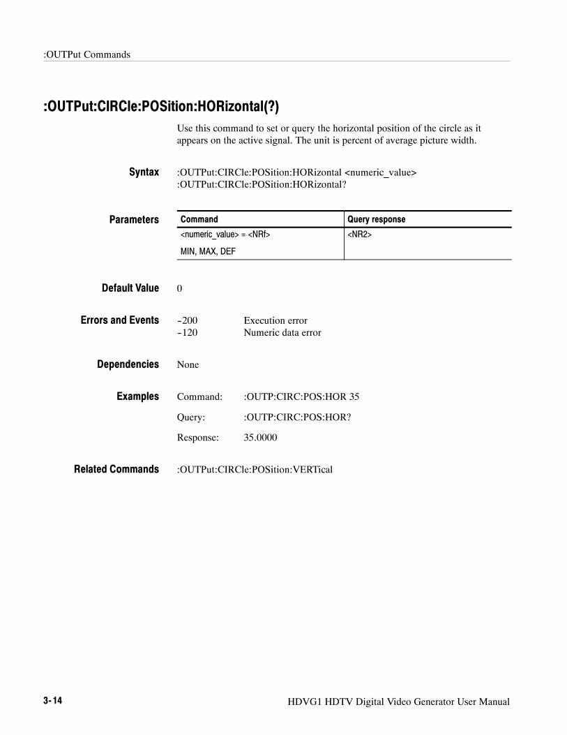
:OUTPut:CIRCle:POSition:HORizontal(?)Use this command to set or query the horizontal position of the circle as itappears on the active signal. The unit is percent of average picture width.
:OUTPut:CIRCle:POSition:HORizontal <numeric_value>:OUTPut:CIRCle:POSition:HORizontal?
Command Query response
<numeric_value> = <NRf>
MIN, MAX, DEF
<NR2>
0
--200 Execution error--120 Numeric data error
None
Command: :OUTP:CIRC:POS:HOR 35
Query: :OUTP:CIRC:POS:HOR?
Response: 35.0000
:OUTPut:CIRCle:POSition:VERTical
Syntax
Parameters
Default Value
Errors and Events
Dependencies
Examples
Related Commands
:OUTPut Commands
HDVG1 HDTV Digital Video Generator User Manual 3- 15
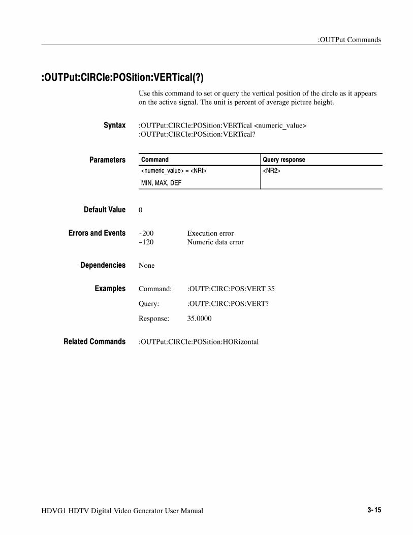
:OUTPut:CIRCle:POSition:VERTical(?)Use this command to set or query the vertical position of the circle as it appearson the active signal. The unit is percent of average picture height.
:OUTPut:CIRCle:POSition:VERTical <numeric_value>:OUTPut:CIRCle:POSition:VERTical?
Command Query response
<numeric_value> = <NRf>
MIN, MAX, DEF
<NR2>
0
--200 Execution error--120 Numeric data error
None
Command: :OUTP:CIRC:POS:VERT 35
Query: :OUTP:CIRC:POS:VERT?
Response: 35.0000
:OUTPut:CIRCle:POSition:HORizontal
Syntax
Parameters
Default Value
Errors and Events
Dependencies
Examples
Related Commands
:OUTPut Commands
3- 16 HDVG1 HDTV Digital Video Generator User Manual
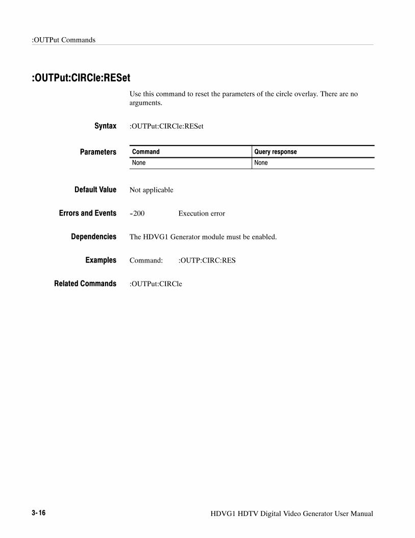
:OUTPut:CIRCle:RESetUse this command to reset the parameters of the circle overlay. There are noarguments.
:OUTPut:CIRCle:RESet
Command Query response
None None
Not applicable
--200 Execution error
The HDVG1 Generator module must be enabled.
Command: :OUTP:CIRC:RES
:OUTPut:CIRCle
Syntax
Parameters
Default Value
Errors and Events
Dependencies
Examples
Related Commands

:OUTPut Commands
HDVG1 HDTV Digital Video Generator User Manual 3- 17
:OUTPut:EAUDio:STATe(?)Use this command to set or query the embedded audio state.
:OUTPut:SERial:EAUDio:STATe <boolean>:OUTPut:SERial:EAUDio:STATe?
Command Query response
<boolean> = ON or 1, OFF or 0 1, 0
ON
--200 Execution error--141 Invalid character data
None
Command: :OUTP:EAUD:STAT ON
Query: :OUTP:EAUD:STAT?
Response: 1
None
Syntax
Parameters
Default Value
Errors and Events
Dependencies
Examples
Related Commands

:OUTPut Commands
3- 18 HDVG1 HDTV Digital Video Generator User Manual
:OUTPut:EAUDio:CHANnel<n>:STATe(?)Use this command to set or query the inactive state of the audio control packetfor a specific embedded audio channel.
The <n> in the command represents the channel number. You can use anychannel number from 1 through 8.
:OUTPut:SERial:EAUDio:CHANnel<n>:STATe <boolean>:OUTPut:SERial:EAUDio:CHANnel<n>:STATe?
Command Query response
<boolean> = ON or 1, OFF or 0 1, 0
ON
--200 Execution error--141 Invalid character data
None
Command: :OUTP:EAUD:CHAN2:STAT ON
Query: :OUTP:EAUD:CHAN2:STAT?
Response: 1
None
Syntax
Parameters
Default Value
Errors and Events
Dependencies
Examples
Related Commands

:OUTPut Commands
HDVG1 HDTV Digital Video Generator User Manual 3- 19
:OUTPut:EAUDio:CHANnel<n>:AMPLitude(?)Use this command to set or query the amplitude of a specific embedded audiochannel. The unit is dBFS.
The <n> in the command represents the channel number. You can use anychannel number from 1 through 8.
:OUTPut:EAUDio:CHANnel<n>:AMPLitude <numeric_value>:OUTPut:EAUDio:CHANnel<n>:AMPLitude?
Command Query response
<numeric_value> = <NRf>--60 ≤ <NRf> ≤ --20
<NR2>
--20
--200 Execution error--104 Data type error
None
Command: :OUTP:EAUD:CHAN1:AMPL 10
Query: :OUTP:EAUD:CHAN1:AMPL?
Response: 10.000
:OUTPut:EAUDio:CHANnel<n>:FREQuency
Syntax
Parameters
Default Value
Errors and Events
Dependencies
Examples
Related Commands
:OUTPut Commands
3- 20 HDVG1 HDTV Digital Video Generator User Manual
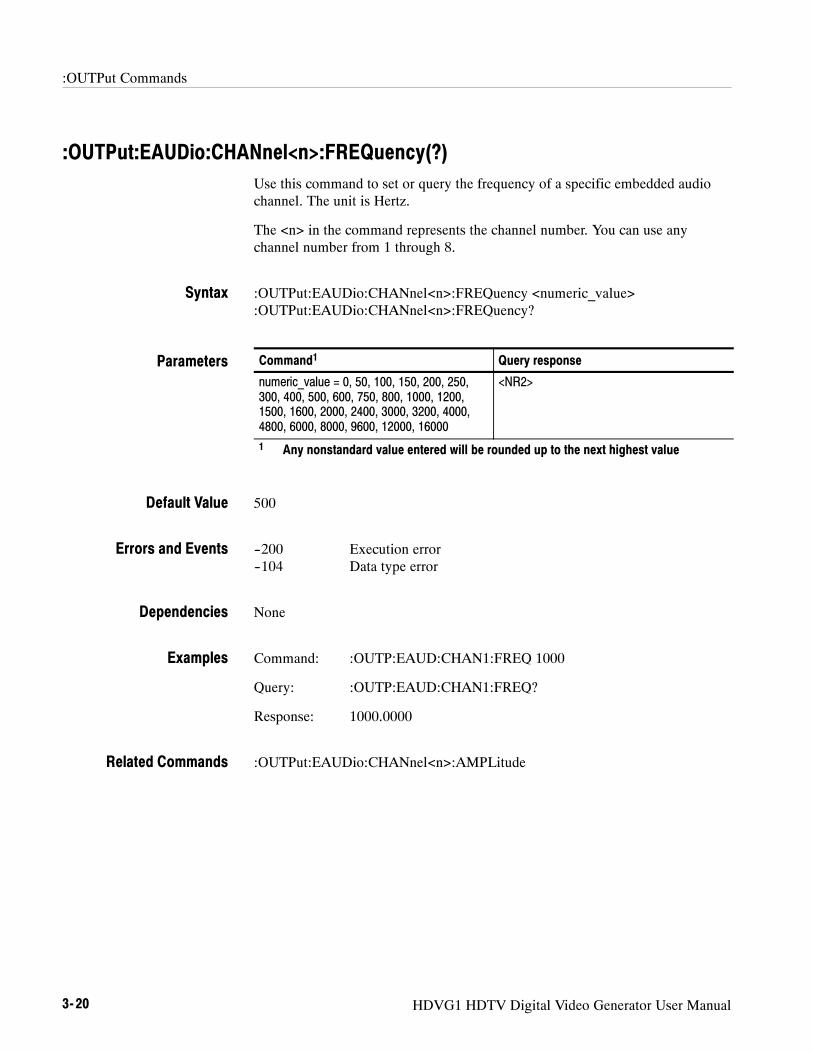
:OUTPut:EAUDio:CHANnel<n>:FREQuency(?)Use this command to set or query the frequency of a specific embedded audiochannel. The unit is Hertz.
The <n> in the command represents the channel number. You can use anychannel number from 1 through 8.
:OUTPut:EAUDio:CHANnel<n>:FREQuency <numeric_value>:OUTPut:EAUDio:CHANnel<n>:FREQuency?
Command1 Query response
numeric_value = 0, 50, 100, 150, 200, 250,300, 400, 500, 600, 750, 800, 1000, 1200,1500, 1600, 2000, 2400, 3000, 3200, 4000,4800, 6000, 8000, 9600, 12000, 16000
<NR2>
1 Any nonstandard value entered will be rounded up to the next highest value
500
--200 Execution error--104 Data type error
None
Command: :OUTP:EAUD:CHAN1:FREQ 1000
Query: :OUTP:EAUD:CHAN1:FREQ?
Response: 1000.0000
:OUTPut:EAUDio:CHANnel<n>:AMPLitude
Syntax
Parameters
Default Value
Errors and Events
Dependencies
Examples
Related Commands

:OUTPut Commands
HDVG1 HDTV Digital Video Generator User Manual 3- 21
:OUTPut:EAUDio:GROup<n>:PREemphasis(?)Use this command to set or query the preemphasis of a specific embedded audiogroup.
The <n> in the command represents the group number. You can use groupnumber 1 and 2.
:OUTPut:EAUDio:GROup<n>:PREemphasis <argument>:OUTPut:EAUDio:GROup<n>:PREemphasis?
Command Query response
<argument> = OFFCDCCITt
OFFCDCCIT
OFF
--200 Execution error--141 Invalid character data--104 Unrecognized character data
None
Command: :OUTP:EAUD:GRO1:PRE CD
Query: :OUTP:EAUD:GRO1:PRE?
Response: CD
None
Syntax
Parameters
Default Value
Errors and Events
Dependencies
Examples
Related Commands

:OUTPut Commands
3- 22 HDVG1 HDTV Digital Video Generator User Manual
:OUTPut:EAUDio:GROup<n>:NBITs(?)Use this command to set or query the sample bits of a specific embedded audiogroup.
The <n> in the command represents the group number. You can use groupnumber 1 and 2.
:OUTPut:EAUDio:GROup<n>:NBITs <numeric_value>:OUTPut:EAUDio:GROup<n>:NBITs?
Command Query response
<numeric value> = 20 or 24 20 or 24
24
--200 Execution error--141 Invalid character data--104 Unrecognized character data
None
Command: :OUTP:EAUD:GRO1:NBIT 24
Query: :OUTP:EAUD:GRO1:NBIT?
Response: 24
None
Syntax
Parameters
Default Value
Errors and Events
Dependencies
Examples
Related Commands

:OUTPut Commands
HDVG1 HDTV Digital Video Generator User Manual 3- 23
:OUTPut:EAUDio:GROup<n>:SAMPling(?)Use this command to select or query the sampling alignment status bit of aspecific embedded audio group.
The <n> in the command represents the group number. You can use groupnumber 1 and 2.
:OUTPut:EAUDio:GROup<n>:SAMPLIng <argument>:OUTPut:EAUDio:GROup<n>:SAMPLIng?
Command Query response
<argument> = FRAMeNOFRameASYNc
FRAMNOFRASYN
FRAM
--200 Execution error--141 Invalid character data--104 Unrecognized character data
None
Command: :OUTP:EAUD:GRO1:SAMPLI FRAM
Query: :OUTP:EAUD:GRO1:SAMPLI?
Response: FRAM
None
Syntax
Parameters
Default Value
Errors and Events
Dependencies
Examples
Related Commands
:OUTPut Commands
3- 24 HDVG1 HDTV Digital Video Generator User Manual
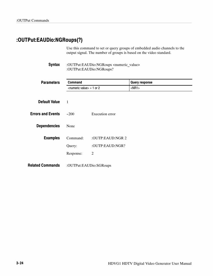
:OUTPut:EAUDio:NGRoups(?)Use this command to set or query groups of embedded audio channels to theoutput signal. The number of groups is based on the video standard.
:OUTPut:EAUDio:NGRoups <numeric_value>:OUTPut:EAUDio:NGRoups?
Command Query response
<numeric value> = 1 or 2 <NR1>
1
--200 Execution error
None
Command: :OUTP:EAUD:NGR 2
Query: :OUTP:EAUD:NGR?
Response: 2
:OUTPut:EAUDio:SGRoups
Syntax
Parameters
Default Value
Errors and Events
Dependencies
Examples
Related Commands

:OUTPut Commands
HDVG1 HDTV Digital Video Generator User Manual 3- 25
:OUTPut:EAUDio:SGRoups(?)Use this command to select the starting group for embeded audio. There are nounits.
:OUTPut:EAUDio:SGRoups <numeric_value>:OUTPut:EAUDio:SGRoups?
Command Query response
<NRf> <NR1>
1
--200 Execution error
HDVG1 Generator module must be enabled.
Command: :OUTP:EAUD:SGR 2
Query: :OUTP:EAUD:SGR?
Response: 2
:OUTPut:EAUDio:NGRoups
Syntax
Parameters
Default Value
Errors and Events
Dependencies
Examples
Related Commands

:OUTPut Commands
3- 26 HDVG1 HDTV Digital Video Generator User Manual
:OUTPut:LOGO:STATe(?)Use this command to set or query the display of the logo overlay onto the videosignal.
NOTE. The settings of the logo overlay are independant of signal activity.
:OUTPut:LOGO:STATe <boolean>:OUTPut:LOGO:STATe?
Command Query response
<boolean> = ON or 1, OFF or 0 1, 0
OFF
--200 Execution error--141 Invalid character data
None
Command: :OUTP:LOGO:STAT 1
Query: :OUTP:LOGO:STAT?
Response: 1
:OUTPut:LOGO:POSition:VERTical,:OUTPut:LOGO:POSition:HORizontal
Syntax
Parameters
Default Value
Errors and Events
Dependencies
Examples
Related Commands

:OUTPut Commands
HDVG1 HDTV Digital Video Generator User Manual 3- 27
:OUTPut:LOGO:POSition:HORizontal(?)Use this command to set or query the horizontal position of the logo as it appearson the active signal. The unit is percent of average picture width.
:OUTPut:LOGO:POSition:HORizontal <numeric_value>:OUTPut:LOGO:POSition:HORizontal?
Command Query response
<numeric_value> = <NRf>--100.0 ≤ <NRf> ≤ 0.0
MIN, MAX, DEF
<NR2>
0
--200 Execution error--120 Numeric data error
None
Command: :OUTP:LOGO:POS:HOR --35
Query: :OUTP:LOGO:POS:HOR?
Response: --35.0000
:OUTPut:LOGO:POSition:VERTical
Syntax
Parameters
Default Value
Errors and Events
Dependencies
Examples
Related Commands
:OUTPut Commands
3- 28 HDVG1 HDTV Digital Video Generator User Manual
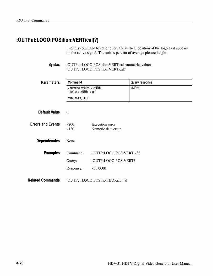
:OUTPut:LOGO:POSition:VERTical(?)Use this command to set or query the vertical position of the logo as it appearson the active signal. The unit is percent of average picture height.
:OUTPut:LOGO:POSition:VERTical <numeric_value>:OUTPut:LOGO:POSition:VERTical?
Command Query response
<numeric_value> = <NRf>--100.0 ≤ <NRf> ≤ 0.0
MIN, MAX, DEF
<NR2>
0
--200 Execution error--120 Numeric data error
None
Command: :OUTP:LOGO:POS:VERT --35
Query: :OUTP:LOGO:POS:VERT?
Response: --35.0000
:OUTPut:LOGO:POSition:HORizontal
Syntax
Parameters
Default Value
Errors and Events
Dependencies
Examples
Related Commands
:OUTPut Commands
HDVG1 HDTV Digital Video Generator User Manual 3- 29
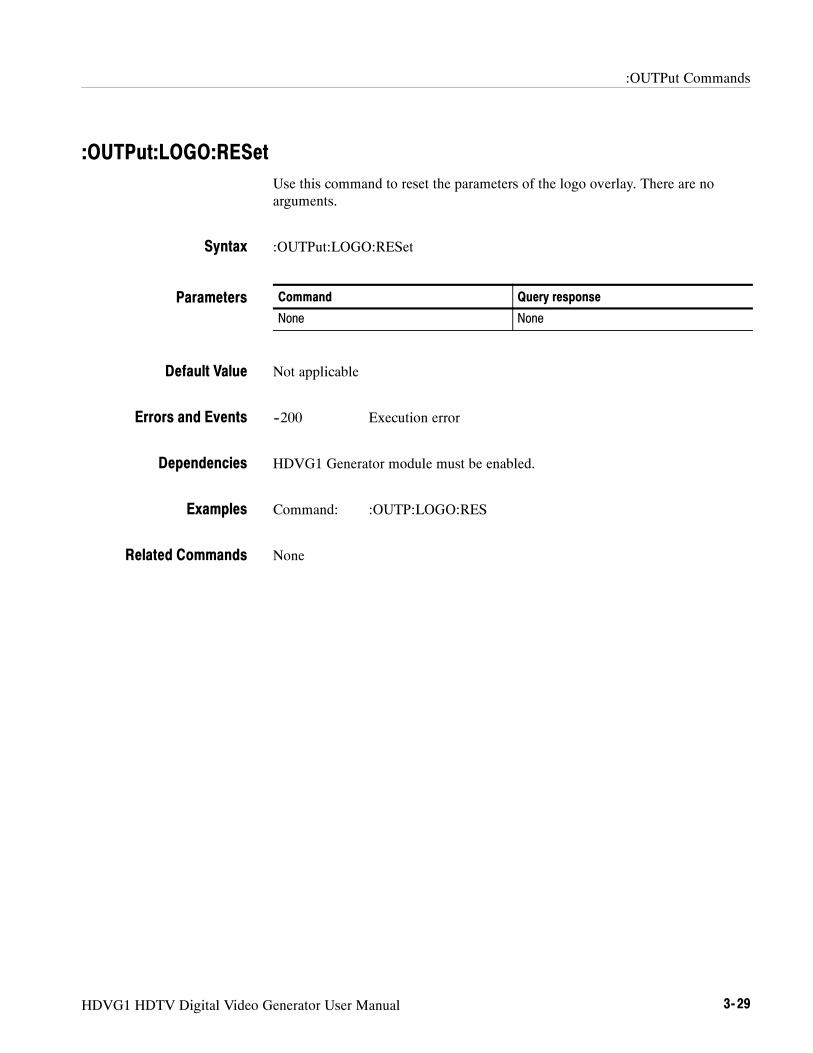
:OUTPut:LOGO:RESetUse this command to reset the parameters of the logo overlay. There are noarguments.
:OUTPut:LOGO:RESet
Command Query response
None None
Not applicable
--200 Execution error
HDVG1 Generator module must be enabled.
Command: :OUTP:LOGO:RES
None
Syntax
Parameters
Default Value
Errors and Events
Dependencies
Examples
Related Commands

:OUTPut Commands
3- 30 HDVG1 HDTV Digital Video Generator User Manual
:OUTPut:LOGO:SELect(?)Use this command to select or query the current logo used for the logo overlay.
:OUTPut:LOGO:SELect <file_name>:OUTPut:LOGO:SELect?
Command Query response
<file_name> = <string> <string>
Not applicable
--200 Execution error
HDVG1 Generator module must be enabled.
Command: :OUTP:LOGO:SEL ”sample.lgo”
Query: :OUTP:LOGO:SEL?
Response: ”sample.lgo”
:OUTPut:LOGO:POSition:HORizontal:OUTPut:LOGO:POSition:VERTical
Syntax
Parameters
Default Value
Errors and Events
Dependencies
Examples
Related Commands

:OUTPut Commands
HDVG1 HDTV Digital Video Generator User Manual 3- 31
:OUTPut:TEXT:STATe(?)Use this command to set or query the text overlay onto the video signal.
:OUTPut:TEXT:STATe <boolean>:OUTPut:TEXT:STATe?
Command Query response
<boolean> = ON or 1, OFF or 0 1, 0
Not applicable
--200 Execution error
None
Command: :OUTP:TEXT:STAT 1
Query: :OUTP:TEXT:STAT?
Response: 1
:OUTPut:TEXT:POSition:VERTical:OUTPut:TEXT:POSition:HORizontal:OUTPut:TEXT:DATA
Syntax
Parameters
Default Value
Errors and Events
Dependencies
Examples
Related Commands

:OUTPut Commands
3- 32 HDVG1 HDTV Digital Video Generator User Manual
:OUTPut:TEXT:DATA(?)Use this command to set or query the current string for the text mode. Textinformation is part of the active signal. To save text with a signal, the signalmust be saved.
:OUTPut:TEXT:DATA <string>:OUTPut:TEXT:DATA?
Command Query response
<string> <string>
Not applicable
--200 Execution error
None
Command: :OUTP:TEXT:DATA ”This is a test.”
Query: :OUTP:TEXT:DATA?
Response: ”This is a test.”
:OUTPut:TEXT:POSition:VERTical:OUTPut:TEXT:POSition:HORizontal
Syntax
Parameters
Default Value
Errors and Events
Dependencies
Examples
Related Commands

:OUTPut Commands
HDVG1 HDTV Digital Video Generator User Manual 3- 33
:OUTPut:TEXT:POSition:HORizontal(?)Use this command to set or query the horizontal position of text in the videosignal. The unit is percentage of average picture width.
:OUTPut:TEXT:POSition:HORizontal <numeric_value>:OUTPut:TEXT:POSition:HORizontal?
Command Query response
<numeric_value> = <NRf>
MIN, MAX, DEF
<NR2>
10
--200 Execution error
None
Command: :OUTP:TEXT:POS:HOR 35
Query: :OUTP:TEXT:POS:HOR?
Response: 35.0000
:OUTPut:TEXT:POSition:VERTical
Syntax
Parameters
Default Value
Errors and Events
Dependencies
Examples
Related Commands

:OUTPut Commands
3- 34 HDVG1 HDTV Digital Video Generator User Manual
:OUTPut:TEXT:POSition:VERTical(?)Use this command to set or query the vertical position of text in the video signal.The unit is percentage of average picture height.
:OUTPut:TEXT:POSition:VERTical <numeric_value>:OUTPut:TEXT:POSition:VERTical?
Command Query response
<numeric_value> = <NRf>
MIN, MAX, DEF
<NR2>
10
--200 Execution error
None
Command: :OUTP:TEXT:POS:VERT 35
Query: :OUTP:TEXT:POS:VERT?
Response: 35.0000
:OUTPut:TEXT:POSition:HORizontal
Syntax
Parameters
Default Value
Errors and Events
Dependencies
Examples
Related Commands
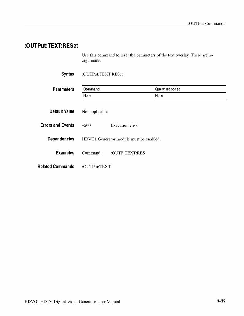
:OUTPut Commands
HDVG1 HDTV Digital Video Generator User Manual 3- 35
:OUTPut:TEXT:RESetUse this command to reset the parameters of the text overlay. There are noarguments.
:OUTPut:TEXT:RESet
Command Query response
None None
Not applicable
--200 Execution error
HDVG1 Generator module must be enabled.
Command: :OUTP:TEXT:RES
:OUTPut:TEXT
Syntax
Parameters
Default Value
Errors and Events
Dependencies
Examples
Related Commands
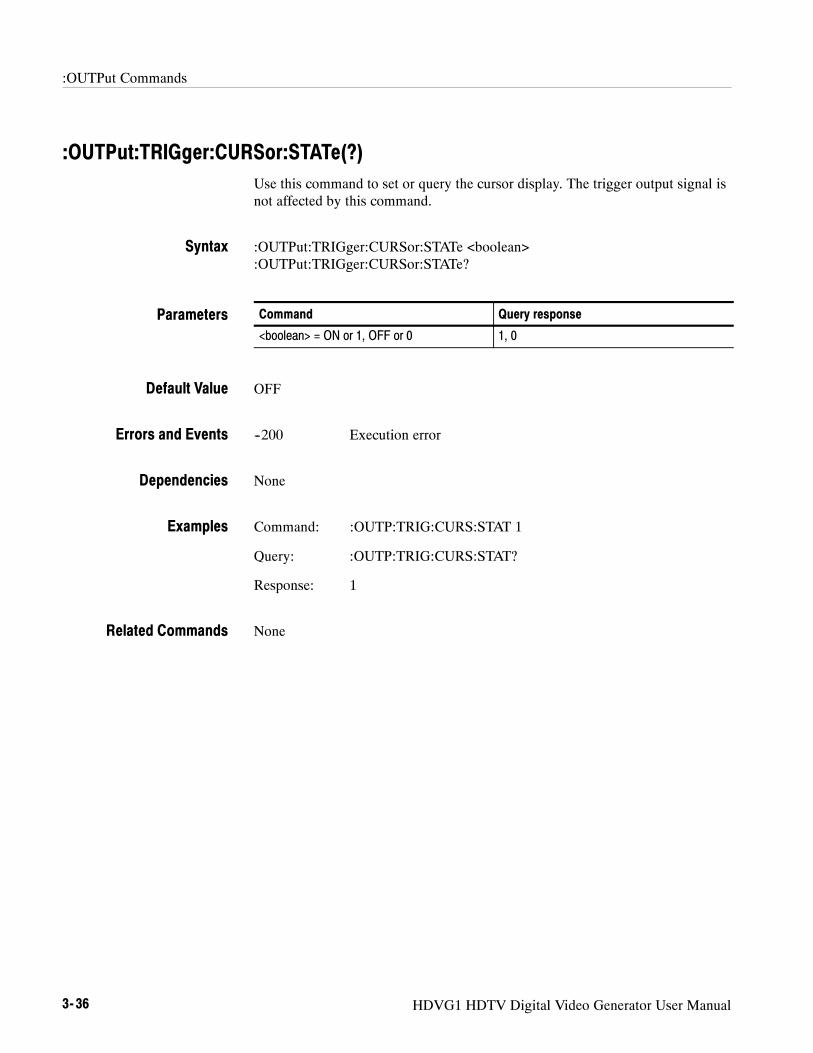
:OUTPut Commands
3- 36 HDVG1 HDTV Digital Video Generator User Manual
:OUTPut:TRIGger:CURSor:STATe(?)Use this command to set or query the cursor display. The trigger output signal isnot affected by this command.
:OUTPut:TRIGger:CURSor:STATe <boolean>:OUTPut:TRIGger:CURSor:STATe?
Command Query response
<boolean> = ON or 1, OFF or 0 1, 0
OFF
--200 Execution error
None
Command: :OUTP:TRIG:CURS:STAT 1
Query: :OUTP:TRIG:CURS:STAT?
Response: 1
None
Syntax
Parameters
Default Value
Errors and Events
Dependencies
Examples
Related Commands

:OUTPut Commands
HDVG1 HDTV Digital Video Generator User Manual 3- 37
:OUTPut:TRIGger:POSition:HORizontal(?)Use this command to set or query the trigger position horizontally within thevideo signal. The unit is microseconds.
NOTE. There is interaction between the vertical and horizontal parameters sincethese parameters combine to resolve any overlap.
:OUTPut:TRIGger:POSition:HORizontal <numeric_value>:OUTPut:TRIGger:POSition:HORizontal?
Command Query response
<numeric_value> = <NRf>
UP, DOWN, DEF
<NR2>
0.0
--200 Execution error
None
Command: :OUTP:TRIG:POS:HOR 32.5
Query: :OUTP:TRIG:POS:HOR?
Response: 32.5000
:OUTPut:TRIGger:POSition:VERTical:OUTPut:TRIGger:POSition:HORizontal:STEP
Syntax
Parameters
Default Value
Errors and Events
Dependencies
Examples
Related Commands

:OUTPut Commands
3- 38 HDVG1 HDTV Digital Video Generator User Manual
:OUTPut:TRIGger:POSition:HORizontal:STEP(?)Use this command to set or query the UP/DOWN step value for the associatedcommand. The unit is microseconds.
:OUTPut:TRIGger:POSition:HORizontal:STEP <numeric_value>:OUTPut:TRIGger:POSition:HORizontal:STEP?
Command Query response
<numeric_value> = <NRf>
MIN, MAX, DEF
<NR2>
1
--200 Execution error
None
Command: :OUTP:TRIG:POS:HOR:STEP 0.5
Query: :OUTP:TRIG:POS:HOR:STEP?
Response: 0.5000
:OUTPut:TRIGger:POSition:HORizontal
Syntax
Parameters
Default Value
Errors and Events
Dependencies
Examples
Related Commands

:OUTPut Commands
HDVG1 HDTV Digital Video Generator User Manual 3- 39
:OUTPut:TRIGger:POSition:HORizontal:SAMPle(?)Use this command to set or query the horizontal parameter of the trigger and itsoverlay. The unit is sample.
:OUTPut:TRIGger:POSition:HORizontal:SAMPle <numeric_value>:OUTPut:TRIGger:POSition:HORizontal:SAMPle?
Command Query response
<numeric_value> = <NRf>
UP, DOWN, DEF
<NR2>
Not applicable
--200 Execution error
HDVG1 Generator module must be enabled.
Command: :OUTP:TRIG:POS:HOR:SAMP 120
Query: :OUTP:TRIG:POS:HOR:SAMP?
Response: 120
:OUTPut:TRIGger:POSition:HORizontal
Syntax
Parameters
Default Value
Errors and Events
Dependencies
Examples
Related Commands

:OUTPut Commands
3- 40 HDVG1 HDTV Digital Video Generator User Manual
:OUTPut:TRIGger:POSition:HORizontal:SAMPle:STEP(?)Use this command to set or query the UP/DOWN step value for the associatedcommand. The unit is sample.
:OUTPut:TRIGger:POSition:HORizontal:SAMPle:STEP <numeric_value>:OUTPut:TRIGger:POSition:HORizontal:SAMPle:STEP?
Command Query response
<numeric_value> = <NRf>
MIN, MAX, DEF
<NR2>
Not applicable
--200 Execution error
HDVG1 Generator module must be enabled.
Command: :OUTP:TRIG:POS:HOR:SAMP:STEP 12
Query: :OUTP:TRIG:POS:HOR:SAMP:STEP?
Response: 12
:OUTPut:TRIGger:POSition:HORizontal:SAMPle
Syntax
Parameters
Default Value
Errors and Events
Dependencies
Examples
Related Commands
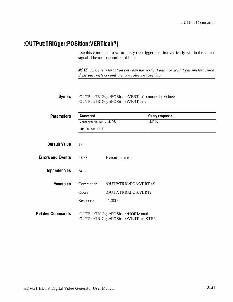
:OUTPut Commands
HDVG1 HDTV Digital Video Generator User Manual 3- 41
:OUTPut:TRIGger:POSition:VERTical(?)Use this command to set or query the trigger position vertically within the videosignal. The unit is number of lines.
NOTE. There is interaction between the vertical and horizontal parameters sincethese parameters combine to resolve any overlap.
:OUTPut:TRIGger:POSition:VERTical <numeric_value>:OUTPut:TRIGger:POSition:VERTical?
Command Query response
<numeric_value> = <NRf>
UP, DOWN, DEF
<NR2>
1.0
--200 Execution error
None
Command: :OUTP:TRIG:POS:VERT 45
Query: :OUTP:TRIG:POS:VERT?
Response: 45.0000
:OUTPut:TRIGger:POSition:HORizontal:OUTPut:TRIGger:POSition:VERTical:STEP
Syntax
Parameters
Default Value
Errors and Events
Dependencies
Examples
Related Commands

:OUTPut Commands
3- 42 HDVG1 HDTV Digital Video Generator User Manual
:OUTPut:TRIGger:POSition:VERTical:STEP(?)Use this command to set or query the UP/DOWN step value for the associatedcommand. The unit is number of lines.
:OUTPut:TRIGger:POSition:VERTical:STEP <numeric_value>:OUTPut:TRIGger:POSition:VERTical:STEP?
Command Query response
<numeric_value> = <NRf>
MIN, MAX, DEF
<NR2>
1.0
--200 Execution error
None
Command: :OUTP:TRIG:POS:VERT:STEP 5
Query: :OUTP:TRIG:POS:VERT:STEP?
Response: 5.0000
:OUTPut:TRIGger:POSition:VERTical
Syntax
Parameters
Default Value
Errors and Events
Dependencies
Examples
Related Commands

:OUTPut Commands
HDVG1 HDTV Digital Video Generator User Manual 3- 43
:OUTPut:TRIGger:TYPE(?)Use this command to select or query the trigger and cursor display types. Theselections affect the type of cursor displayed and the occurrence of the triggeroutput.
There are four trigger types:
H PIXel: a trigger occurs where the horizontal and vertical lines cross
H VERTical: a trigger occurs at the horizontal line (1 pulse per frame)
H HORizontal: a trigger occurs at the vertical line (1 pulse per line)
H OFF: no trigger output
:OUTPut:TRIGger:TYPE <type>:OUTPut:TRIGger:TYPE?
Command Query response
<type> = PIXelVERTicalHORizontalOFF
PIXVERTHOROFF
PIX
--200 Execution error--141 Invalid character data
None
Command: :OUTP:TRIG:TYPE PIXEL
Query: :OUTP:TRIG:TYPE?
Response: PIX
None
Syntax
Parameters
DEfault Value
Errors and Events
Dependencies
Examples
Related Commands

:OUTPut Commands
3- 44 HDVG1 HDTV Digital Video Generator User Manual
:OUTPut:TRIGger:RESetUse this command to reset the parameters of the trigger and its overlay. There areno arguments.
:OUTPut:TRIGger:RESet
Command Query response
None None
Not applicable
--200 Execution error
HDVG1 Generator module must be enabled.
Command: :OUTP:TRIG:RES
:OUTPut:TRIGger
Syntax
Parameters
Default Value
Errors and Events
Dependencies
Examples
Related Commands

HDVG1 HDTV Digital Video Generator User Manual 3- 45
:SENSe Subsystem
Use these commands to adjust the timing of the module in relation to theinstrument. The adjustments set the module delay.
Command Tree:SENSe
:CORRection:MDELay
:VERTical <numeric_value>:STEP <numeric_value>
:HORizontal <numeric_value>:STEP <numeric_value>
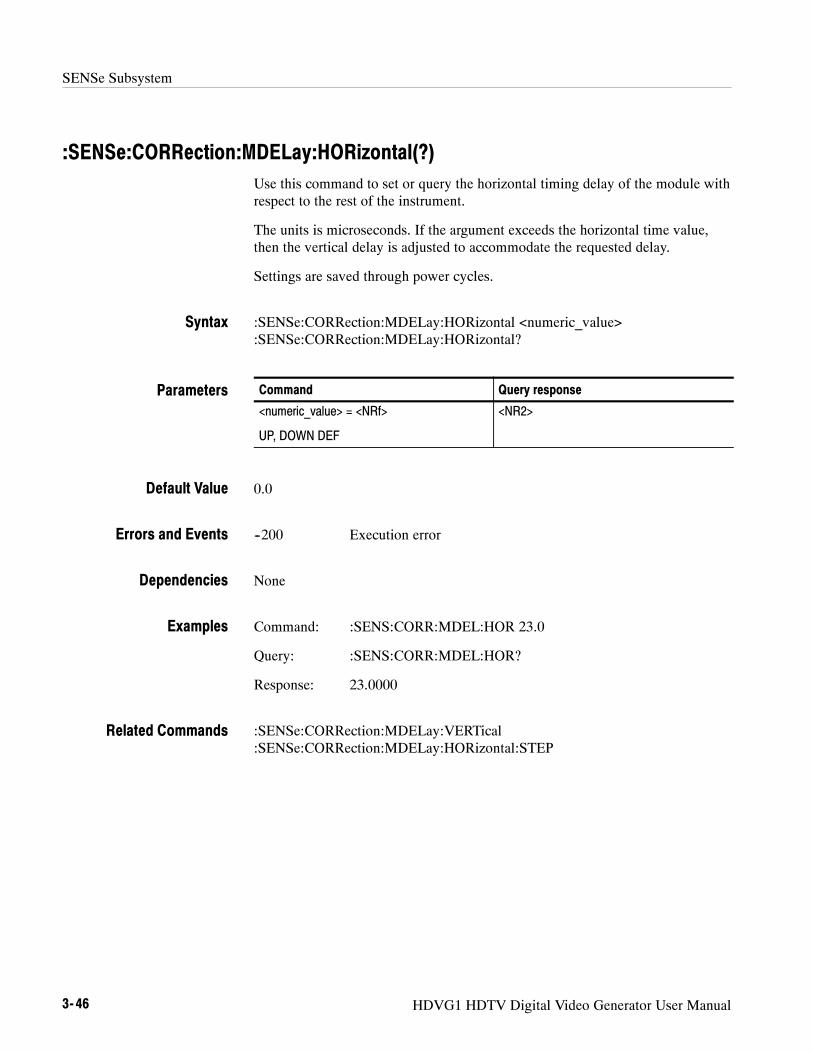
SENSe Subsystem
3- 46 HDVG1 HDTV Digital Video Generator User Manual
:SENSe:CORRection:MDELay:HORizontal(?)Use this command to set or query the horizontal timing delay of the module withrespect to the rest of the instrument.
The units is microseconds. If the argument exceeds the horizontal time value,then the vertical delay is adjusted to accommodate the requested delay.
Settings are saved through power cycles.
:SENSe:CORRection:MDELay:HORizontal <numeric_value>:SENSe:CORRection:MDELay:HORizontal?
Command Query response
<numeric_value> = <NRf>
UP, DOWN DEF
<NR2>
0.0
--200 Execution error
None
Command: :SENS:CORR:MDEL:HOR 23.0
Query: :SENS:CORR:MDEL:HOR?
Response: 23.0000
:SENSe:CORRection:MDELay:VERTical:SENSe:CORRection:MDELay:HORizontal:STEP
Syntax
Parameters
Default Value
Errors and Events
Dependencies
Examples
Related Commands

SENSe Subsystem
HDVG1 HDTV Digital Video Generator User Manual 3- 47
:SENSe:CORRection:MDELay:HORizontal:STEP(?)Use this command to set or query the step increment used by the UP or DOWNcommands. The unit is microseconds.
:SENSe:CORRection:MDELay:HORizontal:STEP <numeric_value>:SENSe:CORRection:MDELay:HORizontal:STEP?
Command Query response
<numeric_value> = <NRf>
MIN, MAX, DEF
<NR2>
1.0000
--200 Execution error
None
Command: :SENS:CORR:MDEL:HOR:STEP 5
Query: :SENS:CORR:MDEL:HOR:STEP?
Response: 5.0000
:SENSe:CORRection:MDELay:HORizontal
Syntax
Parameters
Default Value
Errors and Events
Dependencies
Examples
Related Commands

SENSe Subsystem
3- 48 HDVG1 HDTV Digital Video Generator User Manual
:SENSe:CORRection:MDELay:VERTical(?)Use this command to set or query the vertical time delay of the module. Theargument can be an floating point value that is translated into integer lines with ahorizontal offset.
The query returns an integer value even if the command used a floating pointargument. (The fractional parts are used to adjust the HORizontal offset.)
Settings are saved through power cycles.
:SENSe:CORRection:MDELay:VERTical <numeric_value>:SENSe:CORRection:MDELay:VERTical?
Command Query response
<numeric_value> = <NRf>
UP, DOWN DEF
<NR2>
0
--200 Execution error
None
Command: :SENS:CORR:MDEL:VERT 12
Query: :SENS:CORR:MDEL:VERT?
Response: 12.0000
:SENSe:CORRection:MDELay:HORizontal:SENSe:CORRection:MDELay:VERTical:STEP
Syntax
Parameters
Default Value
Errors and Events
Dependencies
Examples
Related Commands

SENSe Subsystem
HDVG1 HDTV Digital Video Generator User Manual 3- 49
:SENSe:CORRection:MDELay:VERTical:STEP(?)Use this command to set or query the UP/DOWN step value of the associatedcommand.
:SENSe:CORRection:MDELay:VERTical:STEP? <numeric_value>
Command Query response
<numeric_value> = <NRf>
MIN, MAX, DEF
<NR2>
1.0
--200 Execution error
None
Command: :SENS:CORR:MDEL:VERT:STEP 2
Query: :SENS:CORR:MDEL:VERT:STEP?
Response: 2.0000
:SENSe:CORRection:MDElay:VERTical
Syntax
Parameters
Default Value
Errors and Events
Dependencies
Examples
Related Commands

SENSe Subsystem
3- 50 HDVG1 HDTV Digital Video Generator User Manual

HDVG1 HDTV Digital Video Generator User Manual 3- 51
:SOURce Commands
Use the SOURce commands to control the signal source for the module. Thesecommands display the signal name and enable the adjustment of many parame-ters.
Command Tree:SOURce
:MVIDeo:AVIDeo <numeric_value>
:STEP <numeric_value>:CHRoma
:AMPLitude <numeric_value>:STEP <numeric_value>
:LUMinance <numeric_value>:STEP <numeric_value>
:PB <numeric_value>:STEP <numeric_value>
:PR <numeric_value>:STEP <numeric_value>
:TIMEbase <numeric_value>:STEP <numeric_value>

:SOURce Commands
3- 52 HDVG1 HDTV Digital Video Generator User Manual
:SOURce:MVIDeo:AVIDeo(?)Use this command to set or query the amplitude of the active video portion of thevideo signal.
:SOURce:MVIDeo:AVIDeo <numeric_value>:SOURce:MVIDeo:AVIDeo?
Command Query response
<numeric_value> = <NRf>
MIN, MAX, UP, DOWN DEF
<NR2>
100 PCT
--200 Execution error
There is interaction with other parameters that address amplitudes
Command: :SOUR:MVID:AVID 20
Query: :SOUR:MVID:AVID?
Response: 20.0000
None
Syntax
Parameters
Default Value
Errors and Events
Dependencies
Examples
Related Commands

:SOURce Commands
HDVG1 HDTV Digital Video Generator User Manual 3- 53
:SOURce:MVIDeo:AVIDeo:STEP(?)Use this command to set or query the UP/DOWN step value of the active videoportion of the video signal.
:SOURce:MVIDeo:AVIDeo:STEP <numeric_value>:SOURce:MVIDeo:AVIDeo:STEP?
Command Query response
<numeric_value> = <NRf>
MIN, MAX, DEF
<NR2>
1.0 PCT
--200 Execution error
None
Command: :SOUR:MVID:AVID:STEP 5
Query: :SOUR:MVID:AVID:STEP?
Response: 5.0000
None
Syntax
Parameters
Default Value
Errors and Events
Dependencies
Examples
Related Commands
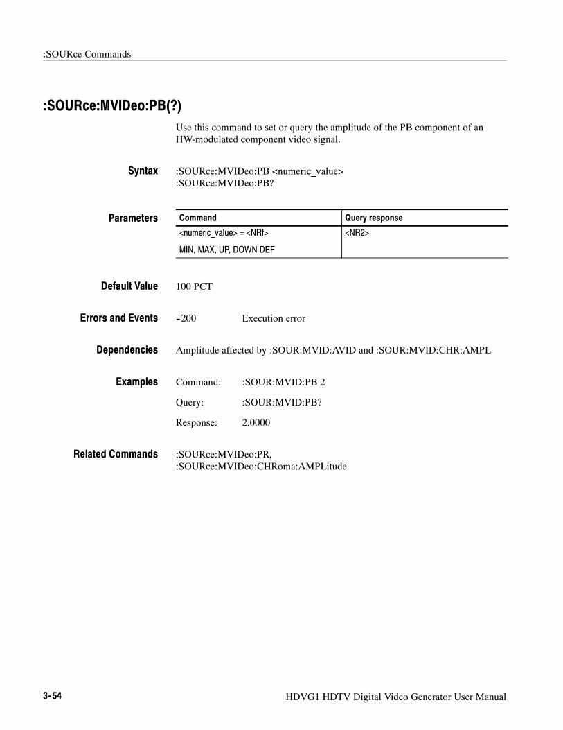
:SOURce Commands
3- 54 HDVG1 HDTV Digital Video Generator User Manual
:SOURce:MVIDeo:PB(?)Use this command to set or query the amplitude of the PB component of anHW-modulated component video signal.
:SOURce:MVIDeo:PB <numeric_value>:SOURce:MVIDeo:PB?
Command Query response
<numeric_value> = <NRf>
MIN, MAX, UP, DOWN DEF
<NR2>
100 PCT
--200 Execution error
Amplitude affected by :SOUR:MVID:AVID and :SOUR:MVID:CHR:AMPL
Command: :SOUR:MVID:PB 2
Query: :SOUR:MVID:PB?
Response: 2.0000
:SOURce:MVIDeo:PR,:SOURce:MVIDeo:CHRoma:AMPLitude
Syntax
Parameters
Default Value
Errors and Events
Dependencies
Examples
Related Commands
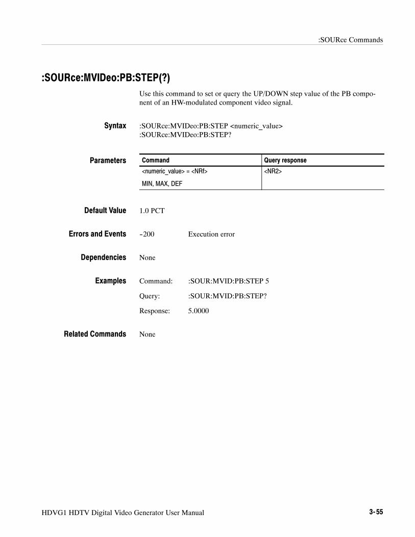
:SOURce Commands
HDVG1 HDTV Digital Video Generator User Manual 3- 55
:SOURce:MVIDeo:PB:STEP(?)Use this command to set or query the UP/DOWN step value of the PB compo-nent of an HW-modulated component video signal.
:SOURce:MVIDeo:PB:STEP <numeric_value>:SOURce:MVIDeo:PB:STEP?
Command Query response
<numeric_value> = <NRf>
MIN, MAX, DEF
<NR2>
1.0 PCT
--200 Execution error
None
Command: :SOUR:MVID:PB:STEP 5
Query: :SOUR:MVID:PB:STEP?
Response: 5.0000
None
Syntax
Parameters
Default Value
Errors and Events
Dependencies
Examples
Related Commands

:SOURce Commands
3- 56 HDVG1 HDTV Digital Video Generator User Manual
:SOURce:MVIDeo:CHRoma:AMPLitude(?)Use this command to set or query the amplitude of the chroma portion of anHW-modulated component video signal.
:SOURce:MVIDeo:CHRoma:AMPLitude <numeric_value>:SOURce:MVIDeo:CHRoma:AMPLitude?
Command Query response
<numeric_value> = <NRf>
MIN, MAX, UP, DOWN DEF
<NR2>
100 PCT
--200 Execution error
Amplitude affected by :SOUR:MVID:AVID (This affects :RY and :BY)
Command: :SOUR:MVID:CHR:AMPL 90
Query: :SOUR:MVID:CHR:AMPL?
Response: 90.0000
None
Syntax
Parameters
Default Value
Errors and Events
Dependencies
Examples
Related Commands

:SOURce Commands
HDVG1 HDTV Digital Video Generator User Manual 3- 57
:SOURce:MVIDeo:CHRoma:AMPLitude:STEP(?)Use this command to set or query the UP/DOWN step value of the chromaportion of an HW-modulated component video signal.
:SOURce:MVIDeo:CHRoma:AMPLitude:STEP <numeric_value>:SOURce:MVIDeo:CHRoma:AMPLitude:STEP?
Command Query response
<numeric_value> = <NRf>
MIN, MAX, DEF
<NR2>
1.0 PCT
--200 Execution error
None
Command: :SOUR:MVID:CHR:AMPL:STEP 5
Query: :SOUR:MVID:CHR:AMPL:STEP?
Response: 5.0000
None
Syntax
Parameters
Default Value
Errors and Events
Dependencies
Examples
Related Commands
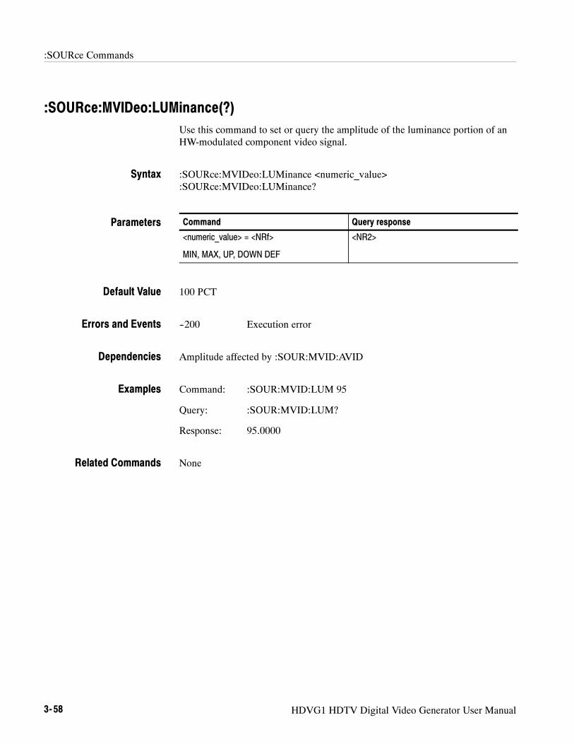
:SOURce Commands
3- 58 HDVG1 HDTV Digital Video Generator User Manual
:SOURce:MVIDeo:LUMinance(?)Use this command to set or query the amplitude of the luminance portion of anHW-modulated component video signal.
:SOURce:MVIDeo:LUMinance <numeric_value>:SOURce:MVIDeo:LUMinance?
Command Query response
<numeric_value> = <NRf>
MIN, MAX, UP, DOWN DEF
<NR2>
100 PCT
--200 Execution error
Amplitude affected by :SOUR:MVID:AVID
Command: :SOUR:MVID:LUM 95
Query: :SOUR:MVID:LUM?
Response: 95.0000
None
Syntax
Parameters
Default Value
Errors and Events
Dependencies
Examples
Related Commands

:SOURce Commands
HDVG1 HDTV Digital Video Generator User Manual 3- 59
:SOURce:MVIDeo:LUMinance:STEP(?)Use this command to set or query the UP/DOWN step value of the luminanceportion of an HW-modulated component video signal.
:SOURce:MVIDeo:LUMinance:STEP <numeric_value>:SOURce:MVIDeo:LUMinance:STEP?
Command Query response
<numeric_value> = <NRf>
MIN, MAX, DEF
<NR2>
1.0 PCT
--200 Execution error
None
Command: :SOUR:MVID:LUM:STEP 5
Query: :SOUR:MVID:LUM:STEP?
Response: 5.0000
None
Syntax
Parameters
Default Value
Errors and Events
Dependencies
Examples
Related Commands

:SOURce Commands
3- 60 HDVG1 HDTV Digital Video Generator User Manual
:SOURce:MVIDeo:PR(?)Use this command to set or query the amplitude of the PR component of anHW-modulated component video signal.
:SOURce:MVIDeo:PR <numeric_value>:SOURce:MVIDeo:PR?
Command Query response
<numeric_value> = <NRf>
MIN, MAX, UP, DOWN DEF
<NR2>
100 PCT
--200 Execution error
Amplitude affected by :SOUR:MVID:AVID and :SOUR:MVID:CHR:AMPL
Command: :SOUR:MVID:PR 80
Query: :SOUR:MVID:PR?
Response: 80.0000
:SOURce:MVIDeo:PB,:SOURce:MVIDeo:CHRoma:AMPLitude
Syntax
Parameters
Default Value
Errors and Events
Dependencies
Examples
Related Commands

:SOURce Commands
HDVG1 HDTV Digital Video Generator User Manual 3- 61
:SOURce:MVIDeo:PR:STEP(?)Use this command to set or query the UP/DOWN step value of the PR compo-nent of an HW-modulated component video signal.
:SOURce:MVIDeo:PR:STEP <numeric_value>:SOURce:MVIDeo:PR:STEP?
Command Query response
<numeric_value> = <NRf>
MIN, MAX, DEF
<NR2>
1.0 PCT
--200 Execution error
None
Command: :SOUR:MVID:PR:STEP 2
Query: :SOUR:MVID:PR:STEP?
Response: 2.0000
None
Syntax
Parameters
Default Value
Errors and Events
Dependencies
Examples
Related Commands

:SOURce Commands
3- 62 HDVG1 HDTV Digital Video Generator User Manual
:SOURce:MVIDeo:TIMEbase(?)Use this command to set or query the underlying timebase of the module. Theunits are PPM.
If the first argument is zero, an optional argument of FRAMe or NOFRame willenable or disable the frame reset for the signal. The default is NOFRame.
If the first argument is a nonzero value, it will override an optional argument ofFRAMe, defaulting to NOFRame.
:SOURce:MVIDeo:TIMEbase <numeric_value>:SOURce:MVIDeo:TIMEbase?
Command Query response
<numeric_value> = <NRf>
MIN, MAX, UP, DOWN, DEF
<frame> =.NOFRame | FRAMe
<NR2>, NOFR
<NR2>, FRAM
0
--200 Execution error
HDVG1 module must be enabled.
Command: :SOUR:MVID:TIME 20
Query: :SOUR:MVID:TIME?
Response: 20,NOFR
:SOURce:MVIDeo
Syntax
Parameters
Default Value
Errors and Events
Dependencies
Examples
Related Commands

:SOURce Commands
HDVG1 HDTV Digital Video Generator User Manual 3- 63
:SOURce:MVIDeo:TIMEbase:STEP(?)Use this command to change the UP/DOWN step value for the associatedcommand. The units are PPM.
:SOURce:MVIDeo:TIMEbase <numeric_value>:SOURce:MVIDeo:TIMEbase?
Command Query response
<numeric_value> = <NRf>
MIN, MAX, DEF
<NR2>
1
--200 Execution error
HDVG1 module must be enabled.
Command: :SOUR:MVID:TIME:STEP 2
Query: :SOUR:MVID:TIME:STEP?
Response: 2.0
:SOURce:MVIDeo:TIMEbase
Syntax
Parameters
Default Value
Errors and Events
Dependencies
Examples
Related Commands

:SOURce Commands
3- 64 HDVG1 HDTV Digital Video Generator User Manual

Appendices

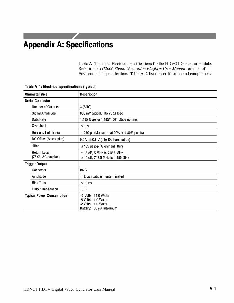
HDVG1 HDTV Digital Video Generator User Manual A- 1
Appendix A: Specifications
Table A--1 lists the Electrical specifications for the HDVG1 Generator module.Refer to the TG2000 Signal Generation Platform User Manual for a list ofEnvironmental specifications. Table A--2 list the certification and compliances.
Table A- 1: Electrical specifications (typical)
Characteristics Description
Serial Connector
Number of Outputs 3 (BNC)
Signal Amplitude 800 mV typical, into 75Ω load
Data Rate 1.485 Gbps or 1.485/1.001 Gbps nominal
Overshoot ≤10%Rise and Fall Times ≤270 ps (Measured at 20% and 80% points)
DC Offset (Ac coupled) 0.0 V0.5 V (Into DC termination)Jitter ≤135 ps p-p (Alignment jitter)Return Loss(75Ω, AC coupled)
≥15 dB, 5 MHz to 742.5 MHz≥10 dB, 742.5 MHz to 1.485 GHz
Trigger Output
Connector BNC
Amplitude TTL compatible if unterminated
Rise Time ≤10 nsOutput Impedance 75Ω
Typical Power Consumption +5 Volts: 14.0 Watts-5 Volts: 1.0 Watts-2 Volts: 1.0 WattsBattery: 30 mA maximum

Appendix A: Specifications
A- 2 HDVG1 HDTV Digital Video Generator User Manual
Table A- 2: Certifications and compliances
Category Standards or description
EC Declaration of Conformity --EMC
Meets intent of Directive 89/336/EEC for Electromagnetic Compatibility. Compliance wasdemonstrated to the following specifications as listed in the Official Journal of the European Union:
EN 55022 Class B Radiated and Conducted Emissions
EN 55103-1 Emissions:Annex A Magnetic Loop Antenna
EN 55103-2 Immunity:EN 61000-4-2 Electrostatic Discharge ImmunityEN 61000-4-3 Radiated RF Electromagnetic Field Amplitude ModulatedEN 61000-4-4 Electrical Fast Transient ImmunityEN 61000-4-5 Surge ImmunityEN 61000-4-6 Conducted RF Common Mode ImmunityEN 61000-4-11 Power Line Interruption ImmunityAnnex A Magnetic Immunity
Australia/New ZealandDeclaration of Conformity -- EMC
Complies with EMC provision of Radiocommunications Act per the following standard(s):
AS/NZS 2064.1/2 Industrial, Scientific, and Medical Equipment: 1992
FCC Compliance Emissions comply with FCC Code of Federal Regulations 47, Part 15, Subpart B, Class A Limits.
EC Declaration of Conformity --Low Voltage
Compliance was demonstrated to the following specification as listed in the Official Journal of theEuropean Union:
Low Voltage Directive 73/23/EEC, amended by 93/68/EEC
EN 61010-1:1993 Safety requirements for electrical equipment for measurement control andlaboratory use.
Safety Complies with the following safety standards:
UL3111-11 Standard for electrical measuring and test equipment.
CAN/CSA C22.2 No. 1010.11Safety requirements for electrical equipment for measurement, control, andlaboratory use.
IEC61010-11 Safety requirements for electrical equipment for measurement, control,and laboratory use.
1 UL3111-1, CSA C22.2 No. 1010.1, and IEC61010-1 Safety Certification Compliance Altitude (maximum operating) :2000 meters
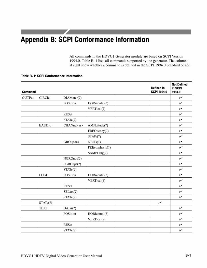
HDVG1 HDTV Digital Video Generator User Manual B- 1
Appendix B: SCPI Conformance Information
All commands in the HDVG1 Generator module are based on SCPI Version1994.0. Table B--1 lists all commands supported by the generator. The columnsat right show whether a command is defined in the SCPI 1994.0 Standard or not.
Table B- 1: SCPI Conformance Information
CommandDefined inSCPI 1994.0
Not DefinedIn SCPI1994.0
OUTPut CIRCle DIAMeter(?) n
POSition HORizontal(?) n
VERTical(?) n
RESet n
STATe(?) n
EAUDio CHANnel<n> AMPLitude(?) n
FREQuency(?) n
STATe(?) n
GROup<n> NBITs(?) n
PREemphasis(?) n
SAMPLIng(?) n
NGROups(?) n
SGROups(?) n
STATe(?) n
LOGO POSition HORizontal(?) n
VERTical(?) n
RESet n
SELect(?) n
STATe(?) n
STATe(?) n
TEXT DATA(?) n
POSition HORizontal(?) n
VERTical(?) n
RESet n
STATe(?) n

Appendix B: SCPI Conformance Information
B- 2 HDVG1 HDTV Digital Video Generator User Manual
Table B- 1: SCPI Conformance Information (Cont.)
Command
Not DefinedIn SCPI1994.0
Defined inSCPI 1994.0
OUTPut TRIGger TYPE(?) n
CURSor STATe(?) n
POSition HORizontal(?) n
STEP(?) n
SAMPle(?) n
STEP(?) n
VERTical(?) n
STEP(?) n
RESet n
SENSe CORRection MDELay HORizontal(?) n
STEP(?) n
VERTical(?) n
STEP(?) n
SOURce MVIDeo AVIDeo(?) n
STEP(?) n
PB(?) n
STEP(?) n
CHRoma AMPLitude(?) n
STEP(?) n
LUMinance(?) n
STEP(?) n
PR(?) n
STEP(?) n
TIMEbase(?) n
STEP(?) n

The following servicing instructions are for use only by qualified personnel. Toavoid injury, do not perform any servicing other than that stated in the operatinginstructions unless you are qualified to do so. Refer to the General SafetySummary and Service Safety Summary before performing any service.
WARNING


HDVG1 HDTV Digital Video Generator S- 1
Service Safety Summary
Only qualified personnel should perform service procedures. Read this ServiceSafety Summary and the General Safety Summary before performing any serviceprocedures.
Do Not Service Alone. Do not perform internal service or adjustments of thisproduct unless another person capable of rendering first aid and resuscitation ispresent.
Disconnect Power. To avoid electric shock, disconnect the main power by meansof the power cord or, if provided, the power switch.
Use Care When Servicing With Power On. Dangerous voltages or currents mayexist in this product. Disconnect power, remove battery (if applicable), anddisconnect test leads before removing protective panels, soldering, or replacingcomponents.
To avoid electric shock, do not touch exposed connections.

Service Safety Summary
S- 2 HDVG1 HDTV Digital Video Generator

HDVG1 HDTV Digital Video Generator User Manual C- 1
Appendix C: Installation
This section covers module installation, signal backup, and module removal.
Preventing Component Damage
CAUTION. Electrostatic discharge (ESD) can damage components on this moduleand mainframe. To prevent ESD or other component damage, follow the stepsbelow when installing, removing, or handling modules:
1. Wear a grounded antistatic wrist strap to discharge the static voltage fromyour body while installing or removing modules from the TG2000 Platformmainframe.
2. Transport and store modules in a static-protected bag or container.
3. Do not slide the module over any surface.
4. Handle modules as little as possible.
5. Do not touch module components or connector pins.
6. Do not use any devices capable of generating or holding a static charge in thework area where you remove, install, or handle modules.
7. Avoid handling modules in areas that have a floor or work-surface coveringcapable of generating a static charge.
8. Do not remove the module circuit board assembly from the shield. Theshield is an important stiffener which prevents damage to surface-mountcomponents.

Appendix C: Installation
C- 2 HDVG1 HDTV Digital Video Generator User Manual
Module InstallationA T-10 torx tip screwdriver is the only tool you need to install the module. AT-10 torx tip is supplied with the module.
To install the module into the TG2000 Platform mainframe, perform these steps:
1. Set the TG2000 Platform mainframe rear-panel power switch to off. Unplugthe power cord.
2. Select the slot you will use to install the module. Table C--1 lists the slotrestrictions. Figure C--1 shows a sample configuration with slot numbers.
Table C- 1: Module slot assignments
Module Slots in which the module can be installed
AGL1 Genlock module Slot 2 or 3
AVG1 Generator module Slots 2 through 10
AWVG1 Generator module Slots 2 through 10
BG1 Generator module Slots 2 through 10
Clock module Slot 1
CPU module Slot 11
DVG1 Generator module Slots 2 through 10
GP1 GPIB Interface module Slot 10
HDVG1 Generator module Slots 2 through 10
GPIBModule
AGL1Module
11 10 9 8 7 6 5 4 3 2 1
CPUModule
AVG1Module
DVG1Module
AWVG1Module
ClockModule
BG1Module
PowerSupply
HDVG1Module
Figure C- 1: Rear panel slot numbering
Hardware Installation

Appendix C: Installation
HDVG1 HDTV Digital Video Generator User Manual C- 3
WARNING. To avoid a shock hazard, always remove the power cord beforeremoving the top cover. Failure to remove the power cord can result in seriousinjury or death.
3. Refer to Figure C--2 and remove or loosen all screws to remove the topcover.
Top cover
Loosen screws (12)
Top cover
Removescrews(23)
Figure C- 2: Top cover removal
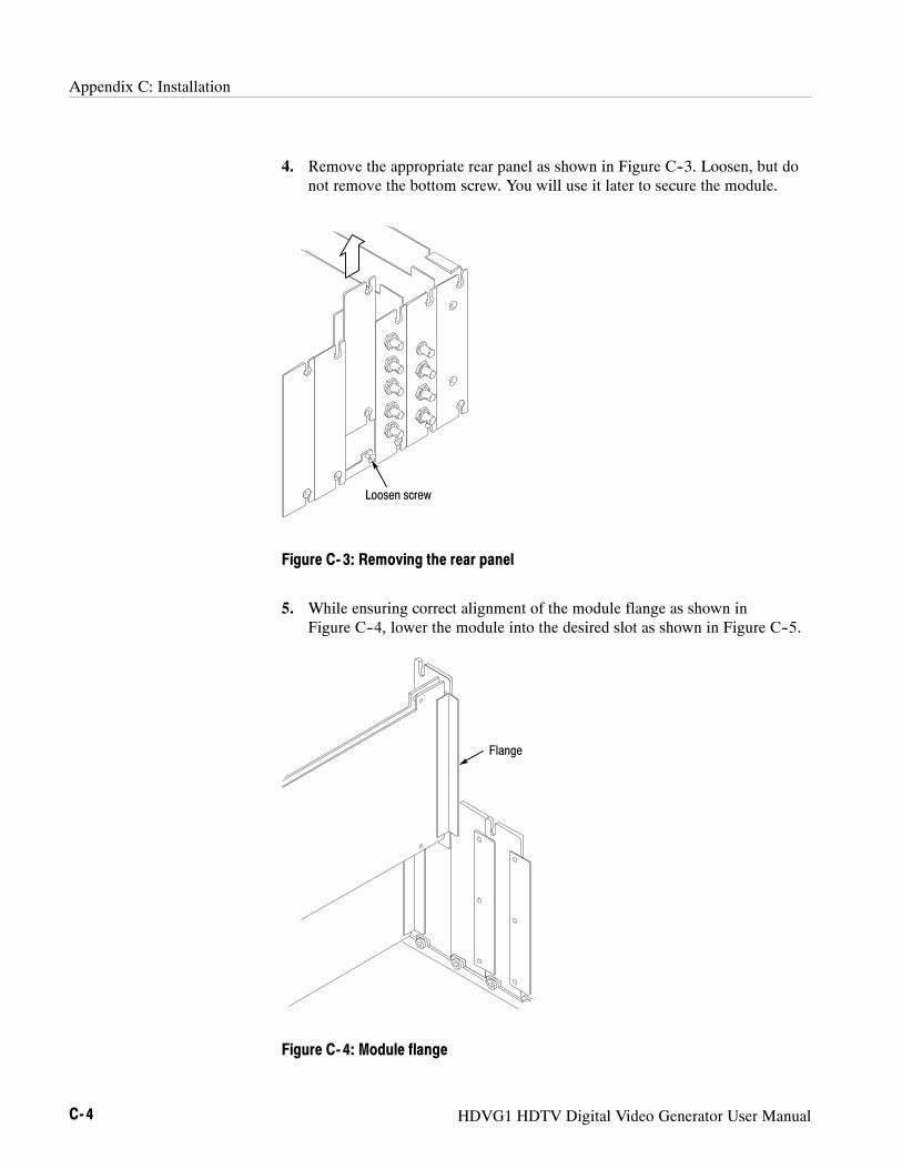
Appendix C: Installation
C- 4 HDVG1 HDTV Digital Video Generator User Manual
4. Remove the appropriate rear panel as shown in Figure C--3. Loosen, but donot remove the bottom screw. You will use it later to secure the module.
Loosen screw
Figure C- 3: Removing the rear panel
5. While ensuring correct alignment of the module flange as shown inFigure C--4, lower the module into the desired slot as shown in Figure C--5.
Flange
Figure C- 4: Module flange
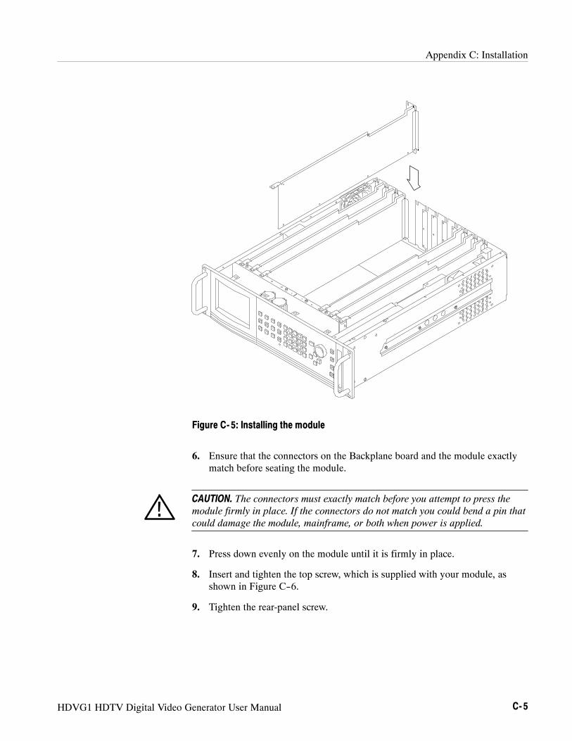
Appendix C: Installation
HDVG1 HDTV Digital Video Generator User Manual C- 5
Figure C- 5: Installing the module
6. Ensure that the connectors on the Backplane board and the module exactlymatch before seating the module.
CAUTION. The connectors must exactly match before you attempt to press themodule firmly in place. If the connectors do not match you could bend a pin thatcould damage the module, mainframe, or both when power is applied.
7. Press down evenly on the module until it is firmly in place.
8. Insert and tighten the top screw, which is supplied with your module, asshown in Figure C--6.
9. Tighten the rear-panel screw.
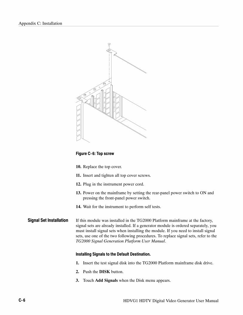
Appendix C: Installation
C- 6 HDVG1 HDTV Digital Video Generator User Manual
Figure C- 6: Top screw
10. Replace the top cover.
11. Insert and tighten all top cover screws.
12. Plug in the instrument power cord.
13. Power on the mainframe by setting the rear-panel power switch to ON andpressing the front-panel power switch.
14. Wait for the instrument to perform self tests.
If this module was installed in the TG2000 Platform mainframe at the factory,signal sets are already installed. If a generator module is ordered separately, youmust install signal sets when installing the module. If you need to install signalsets, use one of the two following procedures. To replace signal sets, refer to theTG2000 Signal Generation Platform User Manual.
Installing Signals to the Default Destination.
1. Insert the test signal disk into the TG2000 Platform mainframe disk drive.
2. Push the DISK button.
3. Touch Add Signals when the Disk menu appears.
Signal Set Installation

Appendix C: Installation
HDVG1 HDTV Digital Video Generator User Manual C- 7
4. Touch Select Source.
5. Use the NAVIGATION arrows to move the cursor to the .DNL (DownloadLibrary) you want to load and push the Select button.
6. Select all of the signal sets at the module level, in the signals field, and pushthe Select button.
7. Touch Quit/Load. The previous menu appears.
8. Touch Quit/Load again. The Add Signals window reappears, showing themodule as the selected destination.
NOTE. The Add Signals window shows the amount of Kbytes selected (TotalTagged) and the amount available on the module. If the tagged total is greaterthan the amount available, the signal sets will not load.
9. Touch Start Load. The signal sets are automatically loaded into the module.A popup window tells you when the transfer is complete.
Installing Signals to a Non-default Destination.
1. Insert the test signal disk into the TG2000 Platform mainframe disk drive.
2. Push the DISK button.
3. Touch Add Signals when the Disk menu appears.
4. Touch Select Source.
5. Move the cursor to the .DNL you want to load and push the Select button.
6. Move the cursor to a particular test signal in the test signal field, and pushthe Select button.
7. Touch Quit/Load. The previous menu appears.
8. Touch Quit/Load again. The Add Signals window reappears.
NOTE. The Add Signals window shows the amount of Kbytes selected (TotalTagged) and the amount available on the module. If the tagged total is greaterthan the amount available, the signal sets will not load.
9. Touch Select Destination.
10. Move the cursor to the signals field and place the cursor where you want thetest signal to be installed. Be sure to chose a destination that is one level
Appendix C: Installation
C- 8 HDVG1 HDTV Digital Video Generator User Manual
above the source (i.e. a signal file must be installed into a signal directory,not into another signal file). Press the Select button.
11. Touch Quit/Load. The Add Signals window reappears.
12. Touch Start Load to start the transfer. A popup window tells you when thetransfer is complete.
Signal Backup and Module RemovalBefore removing a generator module, you should save the signal sets to a disk.The HDVG1 Generator module will lose its signal memory 30 seconds after youremove it from the platform.
Save the signal sets as follows:
1. Insert a DOS formatted disk into the platform’s disk drive.
2. Push the Disk button and touch Save Signals to Disk.
3. Touch Select Source.
4. Use the NAVIGATION arrows to move the cursor to the HDVG1, and pushthe Select button.
5. Move the cursor to the HDVG1 module in the signals field and push theSelect button.
6. Touch Quit/Save.
7. Touch Select Destination and choose A:.
If desired, you may create a new directory for the signals by selecting NewDir and entering a DOS compatible name.
8. You must give the file a new filename. Create a new file by by touching NewFile and entering a DOS compatible name.
9. Touch Quit/Save to return to the Save Signals to Disk window..
10. Touch Start Save. Saving signals may take several minutes, depending onthe number and size of test signals. A popup window tells you when thetransfer is complete.
To remove the module, follow these steps:
1. Turn off the platform by pressing the front-panel On/Standby switch andswitching the rear panel power switch to off.
2. Unplug the power cord.
Signal Backup
Module Removal

Appendix C: Installation
HDVG1 HDTV Digital Video Generator User Manual C- 9
WARNING. To avoid a shock hazard always unplug the power cord beforeremoving the top cover. Failure to unplug the power cord can result in seriousinjury or death.
3. Remove all top-cover screws and remove the top cover. See Figure C--2 onpage C--3.
4. Remove the appropriate rear panel as shown in Figure C--3 on page C--4.Loosen, but do not remove the bottom screw. You will use it later to securethe rear panel.
5. Refer to Figure C--6 on page C--6 and remove the top screw.
CAUTION. The module will lose its signal memory 30 seconds after you remove itfrom the TG2000 Platform mainframe. Before removing the module, be sure youhave performed Signal Backup (page C--8). To save instrument settings andpresets in addition to test signals, you must perform an Instrument Backup,which is described in the HDVG1 Service manual.
6. Remove the module. To leave the slot empty, proceed to step 8 of thisprocedure.
7. To install a module in the empty slot, proceed to Module Installation onpage C--2.
8. To ensure proper cooling and adherence to EMI shielding requirements,install a blank panel to cover any empty slots in the rear panel. A spare blankpanel is included in the TG2000 Platform mainframe accessories kit.
9. Tighten the screws on the blank rear panel.
10. Reinstall the top cover and insert and tighten all top cover screws.
Appendix C: Installation
C- 10 HDVG1 HDTV Digital Video Generator User Manual

Glossary and Index

HDVG1 HDTV Digital Video Generator User Manual Glossary- 1
Glossary
APHActive Picture Height.
Black BurstAlso called “color black,” black burst is a composite video signal consistingof all horizontal and vertical synchronization information and burst.Typically used as the house reference synchronization signal in televisionfacilities.
BurstA small reference packet of the subcarrier sine wave sent on every line ofvideo. Since the carrier is suppressed, this phase and frequency reference isrequired for synchronous demodulation of the color difference signals in thereceiver.
ChrominanceChrominance refers to the color information in a television picture.Chrominance can be further broken down into two properties of color: hueand saturation.
Chrominance SignalThe high-frequency portion of the video signal, obtained by quadratureamplitude modulation of a 4.43 MHz (PAL) or 3.58 MHz (NTSC) subcarrierwith R-Y and B-Y information.
Component VideoA video signal made up of the individual component parts to reproduce acolor picture.
Composite VideoA single video signal containing all of the necessary information toreproduce a color picture. Created by adding quadrature amplitude modu-lated U and V to the luminance signal.
FrameA frame (sometimes called a “picture”) contains all the information requiredfor a complete picture. For interlaced scan systems, there are two fields in aframe.
Glossary
Glossary- 2 HDVG1 HDTV Digital Video Generator User Manual
GBRGreen Blue, and Red. The three primary colors used in color television’sadditive color reproduction system. These are the three color componentsgenerated by the camera and used by the monitor to produce a picture.
LuminanceThe signal which represents brightness, or the amount of light in the picture.This is the only signal required for black and white pictures, and for colorsystems it is obtained as a weighted sum (Y = 0.3R + 0.59G + 0.11B) of theR, G, and B signals.
NTSCNational Television System Committee. The organization that developed thetelevision standard currently in use in the United States, Canada and Japan.
PALPhase Alternate Line. Refers to one of the television systems used in Europeand many other parts of the world. The phase of one of the color differencesignals alternates from line to line to help cancel out phase errors.
PBA color difference signal used in component video systems. It is derived bysubtracting the B (blue) signal from Y.
PRA color difference signal used in component video systems. It is derived bysubtracting the R (red) signal from Y.
Quick Draw ModeEnables an overlay to draw faster while you are changing values. Fullresolution and edge shaping is invoked once values stop changing.
SCPIStandard Commands for Programmable Instruments. SCPI is a standard thatprovides guidelines for remote programming of instruments. Theseguidelines provide a consistent programming environment for instrumentcontrol and data transfer.
Signal SetA set of industry standard test signals provided by Tektronix on floppy disks.
Soft keyAn item on the display that changes state or initiates an action when youtouch it on screen. You use soft keys to select test signals or enter a file name.
Glossary
HDVG1 HDTV Digital Video Generator User Manual Glossary- 3
TerminationIn order to accurately send a signal through a transmission line, there mustbe an impedance at the end which matches the impedance of the source andof the line itself. Amplitude errors and reflections will otherwise result.Video is a 75 Ω system, so a 75 Ω terminator must be put at the end of thesignal path.
YAbbreviation for luminance.

Glossary
Glossary- 4 HDVG1 HDTV Digital Video Generator User Manual

HDVG1 HDTV Digital Video Generator User Manual Index- 1
IndexAAccessoriesoptional, 1--2standard, 1--2
Active Signal Parameters, 2--7Active Signal Parameters window, 2--7Add Logo from Disk window, 2--20Audio Groups window, 2--16
CCertifications and compliances, A--2Circle overlay, 2--14Circle Overlay window, 2--14commandsrules for forming, 3--1syntax, 3--1
DDelete Logo window, 2--20
EElectrical specifications, A--1Embedded audio, 1--2, 2--15Embedded Audio window, 2--15Enable the output signal, 2--15
FFunctional check, 1--3Functional command groups, 3--5Functional overview, 2--1
HHardware installation, C--2HDVG1 features, 1--1Hierarchy (SCPI), 3--4
IInstallation, signal sets, C--6Installlation, hardware, C--2
LLogo File Utilities window, 2--18Logo overlay, 2--17Logo Overlay window, 2--17
MManuals, related, ixMenu structure, 2--1Module, removing, C--8Module Parameters, 2--13Module Parameters window, 2--13Module timing, 2--21Modules window, 2--4
OOnline help, 2--2Option, 1--3Output signal, 2--5Output signal enable, 2--15Outputs, 2--2
PPower on procedure, 2--4Product description, 1--1
RRear-panel connectors, 2--2Related Manuals, ixRemoving a module, C--8rules, command forming, 3--1
SSave Logo to Disk window, 2--18Saving signal sets, C--8SCPIConformance information, B--1subsystem hierarchy tree, 3--4
SCPI commands and queries syntax, 3--4Select output signal, 2--5Select the module, 2--4

Index
Index- 2 HDVG1 HDTV Digital Video Generator User Manual
Signal information, 2--12Signal Information window, 2--12Signal sets installation, C--6Signal Sets window, 2--5Signal sets window, 2--4Signal Text window, 2--10Specifications, A--1Syntax, command, 3--1
TText overlay, 2--10Timing window, 2--21Trigger output, 2--22
VVideo parameters, 2--8Video Parameters window, 2--8
WWindowActive Signal Parameters, 2--7Add Logo from Disk, 2--20Audio Groups, 2--16Circle Overlay, 2--14Delete Logo, 2--20Embedded Audio, 2--15Logo File Utilities, 2--18Logo Overlay, 2--17Module Parameters, 2--13Modules, 2--4Save Logo to Disk, 2--18Signal Information, 2--12Signal Sets, 2--5Signal sets, 2--4Signal Text, 2--10Timing, 2--21Video Parameters, 2--8


