Download - HE Fishing Jars

ES20.39964–
Operation Manual
TMCHydraulic Fishing Jar


This title block page intentionally left blank.
DATE: Jan 30, 2007
DRAWN: M Hutchinson P.O. Box 60068 HOUSTON, TX 77205 APRVD: C Long
INDEX
ES20 Operation Manual
– 26334 Jan 30, 2007 C Long
TMC Hydraulic Fishing Jar
This drawing and data embody proprietary information which is the confidential property of Smith International, Inc., and which shall not be copied, reproduced, disclosed to others, or used in whole or in part for any purpose, without the written permission of Smith. This drawing is loaned in confidence with the understanding that it SPEC. NO. shall be returned on demand. REV ECO DATE BY ES20.39964


TABLE OF CONTENTS
SECTION I - GENERAL INFORMATION. . . . . . . . . . . . . . . . . . . . . . . . . . . . . . . . . . . . . . . 1, 2
SECTION II - FIELD INSTRUCTIONS . . . . . . . . . . . . . . . . . . . . . . . . . . . . . . . . . . . . . . . . . . . 3
FIGURE 1–TMC JAR . . . . . . . . . . . . . . . . . . . . . . . . . . . . . . . . . . . . . . . . . . . . . . . . . . . . 3
BEFORE RUNNING IN THE HOLE . . . . . . . . . . . . . . . . . . . . . . . . . . . . . . . . . . . . . . . . 3
CHANGE OUT RECOMMENDATION . . . . . . . . . . . . . . . . . . . . . . . . . . . . . . . . . . . . . . 4
TABLE 1– CHANGE OUT RECOMENDATION . . . . . . . . . . . . . . . . . . . . . . . . . . . . . . 4
AFTER EACH USE . . . . . . . . . . . . . . . . . . . . . . . . . . . . . . . . . . . . . . . . . . . . . . . . . . . . . . 5
RECOMMENDED STRING HOOK-UP. . . . . . . . . . . . . . . . . . . . . . . . . . . . . . . . . . . . . . 5
FIGURE 2–HYDRAULIC JAR AND ACCELERATOR HOOK-UP. . . . . . . . . . . . . . . . 6
TABLE 2–HYDRAULIC JAR AND ACCELERATOR WEIGHT TABLES . . . . . . . . . 7
TABLE 3–SPECIFICATIONS AND STRENGTH DATA . . . . . . . . . . . . . . . . . . . . . . . . 8
FISHING DIMENSIONS . . . . . . . . . . . . . . . . . . . . . . . . . . . . . . . . . . . . . . . . . . . . . . . 9–14
The last numbered page of this manual is 14.
Effective Date May 2002 TMC Jar
ENC 15667 Operation Manual


SECTION I
GENERAL INFORMATION
The Houston Engineers Series TMC Jar, when connected to the lower end of long resilient tubular drill
strings, utilizes a sequence of detent and free vertical travel to accomplish an impact force in subsurface well
bores. An initial portion of the TMC stroke, or travel, is restricted by the close toleranced hydraulic section. Re-
stricted travel is maintained until the drill pipe or tubing can be placed under conditions of high vertical stress or
stretch. A free, unrestricted, portion of travel within the Jar is provided to allow sudden release of a portion of the
stress in the drill string. Release of stress is utilized to accelerate drill collars or simply the mass of the tubular
string, and to deliver an impact blow at a depth within the confines of the impact section of the TMC Jar. It is
common practice to use drill collars with the TMC Jar to concentrate a large amount of mass just above the Jar
where maximum velocity will occur when the Jar “trips” or when that portion of free travel is activated. The
number of drill collars to be used will depend on surface equipment, well conditions and the nature of the object
lodged within the well bore. The impact delivering capability of the TMC Jar may be enhanced by the use of the
Houston Engineers Series ACCMC Accelerator®. This is a tool capable of accumulating tensile energy and di-
recting this energy to boost the impact blow to much higher levels when the TMC Jar releases. Complete de-
scription and use of TMC Jars and ACCMC Accelerators® is shown on the following pages of this manual.
TMC Jars are long stroke hard hitting jarring tools that have been proven to excel when used as fishing tools,
in conjunction with formation testing and coring tools. The TMC drive system is in an enclosed environment
preventing foreign objects from entering the fluid system. TMC Jars are designed to deliver impact blows in an
upward direction only and are not dependent on torque or rotational motion. A straight upward strain at the sur-
face will achieve the impact action at subsurface depths. Other outstanding features are described and illustrated
in other sections of this manual.
With TMC Jars, the impact action is achieved by the combined use of reliable hydraulic and mechanical prin-
ciples. This Jar will allow sufficient time delay to put the desired strain on the drill string, and will deliver a
strong impact which is completely controlled by the rig operator at all times. Resetting of the Jar is made without
delay and without any internal pressure build-up within the tool.
The time delay is achieved by the retarded upward movement of the inner parts of the TMC Jar when an up-
ward strain is exerted on the drill string. As the piston section of the Detent Mandrel passes through the restric-
tion, fluid slowly bleeds by the close tolerances of the metering system on the Detent Mandrel. As the fluid and
pressure are slowly dissipated through these restrictions, a slow upward movement of the inner parts of the Jar is
accomplished. This relatively slow movement of the inner Jar parts allows the operator to put the desired strain
in the drill string. As the piston clears the upward end of the restriction, the inner parts of the Jar rush upward
with the drill string creating kinetic energy. The upward movement is stopped by the impact surfaces located on
top of the Knocker and in the upper end of the Kelly Cylinder. When these two anvil surfaces meet, kinetic en-
ergy from the rapidly moving drill string is transmitted to the stuck object in the well bore through the outer body
and grappling device below the TMC Jar.
After the impact stroke of the TMC Jar has been made, a rapid resetting action takes place as the drill string is
lowered to its original position. As the piston on the Detent Mandrel re-enters the restriction, instead of retarded
movement as was true on the upstroke, a free and smooth movement in resetting is accomplished. As the piston
enters the restriction, the Detent Ring responds to the unequal pressure tendency and moves up until the bypass
slots are opened and oil is freely transferred in a smooth reset action. Because of the complete resetting action,
Effective Date May 2002 1 TMC Jar
ECN 15667 Operation Manual

the TMC Jar will deliver a controllable bumping down action, in the same manner as a bumper sub, without any
damage to the lower packing.
The torque transmitting means and impact surfaces are in separate closed lubricated environments, prevent-
ing metal shavings from contaminating or fouling the working parts in the hydraulic detent section. All of the
above factors combine to fulfill the needs for an oilfield jarring tool that is simple, rugged and dependable.
All TMC Jars and ACCMC Accelerators®are available in right and left-hand threaded embodiments without
departure from the operating instructions contained in this manual.
TMC Jar 2 Effective Date May 2002
Operation Manual ECN 15667
TMC JAR
HYDRAULIC DETENT
SECTION
NEUTRALIZER
SECTION
WASHPIPE
SECTION
SERIAL NUMBER
TORQUE DRIVE
SECTION

SECTION II
FIELD INSTRUCTIONS
Drill collars used in a position just above the TMC Jar will allow the most efficient use of the weight of the
drill collars to loosen stuck objects by impact blows delivered in an upward direction. After engaging the stuck
object (fish), a strain is taken on the drill string and sufficient time allowed for the TMC Jar to trip. This will gen-
erally be between one to two minutes for the first blow. Successive blows are entirely at the control of the rig op-
erator and can be controlled with regard to frequency and intensity. The frequency is regulated by noting and
marking the pipe or Kelly at the point where they were last closed. If increased Jar frequency is desired, the point
of closure is controlled from the last mark on the Kelly. Increased intensity may be achieved by using an Hous-
ton Engineers Series ACCMC Accelerator® along with the TMC Jar as shown in Fig. 2. Any desired blow may
be delivered by observing the above procedure and is completely controlled by the rig operator. No waiting peri-
od is required to reset the Jar. The Jar will offer absolutely no resistance on the resetting stroke. Frequency of
blow is controlled by distance of travel of the resetting and not by time that weight is placed on the Jar.
BEFORE RUNNING IN THE HOLE: Fill Plugs should be checked for shut-off along with a note of any
leaking hydraulic fluid around the joints of the TMC Jar. The joints of the Jar are made-up in service shops to
proper torque values. However, in some cases it may be desirable to make-up joints to tool joint torque levels
with the rig tongs. The tongs should be placed opposite each of the four breaks in the tool. The tongs should
never be placed in the middle of the Kelly or Detent Cylinders. Tong teeth should not be placed over the Fill Plug
holes and excessive tonging or jerking of the tong line should be avoided. Fig. 1 illustrates the Cylinder Sections
where tongs may be placed.
Effective Date May 2002 3 TMC Jar
ECN 15667 Operation Manual
TMC Jar
FIG. 1
Place Tongs
Here

CHANGE OUT RECOMMENDATIONS: The TMC Jar should be changed out periodically, for servic-
ing. See Table 1, Change Out Recommendations, to determine recommended hours of use before servicing.
TOOL SIZES
Tool Joint
Connection
Normal Jarring or Bumping Operation
Minimum torque and
short durations of torquing
Washover or Millling Opertion
High torque and long duration of torquingO.D.
inches
(mm)
I.D.
inches
(mm) * Hours of Operation Before Change Out
1-13/16
(46)
3/8
(10)1-13/16 WFJ
80 Hours 20-30 Hours1-13/16
(46)
9/16
(14)1 AM MT
2-1/4
(57)
1/2
(13)1-1/4 REG
3-1/8
(79)
1
(25)2-3/8 API REG
120 Hours 30-40 Hours
3-1/8
(79)
1-1/2
(38)2-3/8 EUE
3- 3/4
(95)
1-1/2
(38)2-3/8 API IF
3- 3/4
(95)
2
(51)2-3/8 EUE
4-1/4
(108)
2
(51)2-7/8 API IF
160 Hours 40-50 Hours
4-1/4
(108)
2-7/16
(62)2-7/8 EUE
4-3/4
(121)
2
(51)3-1/2 API FH
4-3/4(121)
2-1/4(57) 3-1/2 API IF
6-1/4(159)
2-1/4(57) 4-1/2 API IF
200 Hours 50-60 Hours
6-1/2
(165)
2-1/4
(57)4-1/2 API IF
7-3/4
(197)
3-1/2
(89)6-5/8 API REG
8
(203)
3-1/2
(89)6-5/8 API REG
Trapping torque while jarring or bumping decreases hours by half, accumulatively.
TMC Jar 4 Effective Date May 2002
Operation Manual ECN 15667
Change Out Recommendations
Table 1

AFTER EACH USE: If TMC Jars have been operating properly, it is not necessary to change Jars on each
trip. However, it is not advisable to leave the tool around corrosive conditions for a prolonged period of time
without at least an oil washout of the Kelly system and into the Washpipe Cylinder and around the Detent Man-
drel.
On completion of a fishing or other jar operation, the TMC Jar joints may be broken with rig tongs observing
the same precautions as mentioned above. The Jar should then be sent to the nearest point of service for a major
service and testing operation.
CAUTION: FAILURE TO PLACE BREAKOUT TONGS IN PROPER POSITION AS SHOWN IN
FIG. 1 MAY CAUSE SEVERE AND EXPENSIVE DAMAGE TO THE JARS.
RECOMMENDED STRING HOOK-UP: Fig. 2 represents a standard recommended fishing hook-up us-
ing the TMC Jar and ACCMC Accelerator®. The number of drill collars placed between the TMC Jar and Accel-
erator is of utmost importance. Prior to the development of the Accelerator, it was accepted practice to run a
large number of drill collars directly above the jar so as to provide a mass for upward impact, however, well con-
ditions such as wall drag, crooked holes, etc, definitely limit the effectiveness of this arrangement.
The TMC Jar or the TMC Jar-ACCMC Accelerator® jar system should be placed as close to the stuck point as
possible. Any “free pipe” located between the jar system and the stuck point may deflect and act as a shock ab-
sorber, preventing delivery of the impact load to the stuck point.
Mechanical principles concerning dynamics show that when the ACCMC Accelerator® is used with the TMC
Jar, impact forces can be generated much higher than the impact force generated by the TMC Jar alone. See
TMC Jar and Accelerator Hook-up, Figure 2, versus the practice of using excessively large numbers of drill col-
lars above the Jar. Use Table 2 to determine the optimum impact weight or the proper number of drill collars to
be placed between the TMC Jar and ACCMC Accelerator®. Failure to use the arrangement in the exact sizes and
weights that are listed will result in less than peak impact efficiency for any given system.
Use of the ACCMC Accelerator® with the TMC Jar not only increases the efficiency of the impact jar capabil-
ity of any fishing string, but the Accelerator® also reduces the amount of shock transmitted up the string towards
the surface. As a result of this capability, the fishing string can be subjected to higher pull effort exerted by sur-
face equipment without fear of overload due to impact shock waves traveling up the fishing string. High inten-
sity impact jar operations can be accomplished without damage to the fishing string.
Smith Services – HE Group does not recommend the use of two TMC Jars in the string at the same time or use
of its TMC Jars with other makes of accelerators. HE Group tools are made in matched sets and will not deliver
impact blows, as calculated, when used in conjunction with other makes of impact equipment.
Effective Date May 2002 5 TMC Jar
ECN 15667 Operation Manual

TMC Jar 6 Effective Date May 2002
Operation Manual ECN 15667
2
TMC JAR and ACCELERATOR HOOK-UP
FIG. 2Use This Figure In Conjunction with Table 2
Jar Load = Surface Pull less
Pipe Wt. and Hole Drag
Optimum Wt. is20% of Jar Load
1
4
3
1
Jar Blow isApprox. 10 times Jar Load
FISHING STRING
Accelerator
Drill Collars
“TMC” HYDRAULIC JAR
Optional Fishing Tools
Stuck Point

To
ol O
.D.
inch
es(m
m)
1-13
/16
(46)
3-1/
8(7
9)3-
3/4
(95)
3-3/
4(9
5)4-
1/4
(108
)4-
3/4
(121
)5-
3/4
(146
)6-
1/4
(159
)6-
3/4
(171
)7-
3/4
(197
)
To
ol J
oin
tC
on
nec
tio
ns
1-13
/16
WF
J2-
3/8
AP
I RE
G2-
3/8
AP
I IF
2-7/
8A
PI R
EG
2-7/
8A
PI I
F3-
1/2
AP
I FH
4-1/
2A
PI F
H4-
1/2
AP
I IF
5-1/
2A
PI R
EG
6-5/
8A
PI R
EG
Jar
and
Acc
el. L
oad
lbf
(N)
Wei
gh
t o
f C
olla
rs a
nd
Qu
anti
ty o
f C
olla
rs—
lb. (
kg)
5,00
0(2
2,24
0)1,
000
4(4
544)
10,0
00(4
4,48
0)2,
000
8(9
078)
15,0
00(6
6,72
0)3,
000
12(1
,361
12)
3,00
04
(1,3
614)
3,00
03
(1,3
613)
3000
3(1
,361
3)
20,0
00(8
8,96
0)4,
000
16(1
,814
16)
4,00
06
(1,8
146)
4,00
04
(1,8
144)
4000
4(1
,814
4)
4,00
04
(1,8
144)
25,0
00(1
11,2
00)
5,00
07
(2,2
687)
5,00
05
(2,2
685)
5,00
0 5
(2,2
68 5
)5,
000
4(2
,268
4)30
,000
(133
,440
)6,
000
8(2
,722
8)6,
000
6(2
,722
6)60
00 6
(2,7
22 6
)6,
000
5(2
,722
5)35
,000
(155
,680
)7,
000
9(3
,175
9)7,
000
7(3
,175
7)70
00 7
(3,1
75 7
)7,
000
6(3
175
6)40
,000
(177
,920
)8,
000
10(3
,628
10)
8,00
08
(3,6
288)
8,00
0 8
(3,6
28 8
)8,
000
7(3
,628
7)50
,000
(222
,400
)10
,000
13(4
,536
13)
10,0
0011
(4,5
3611
)10
,000
10
(4,5
36 1
0)10
,000
9(4
,536
9)10
,000
7(4
,536
7)10
,000
4(4
,536
4)55
,000
(244
,640
)11
,000
12(4
,990
12)
11,0
00 1
1(4
,990
11)
11,0
0010
(4,9
9010
)11
,000
7(4
,990
7)11
,000
4(4
,990
4)60
,000
(266
,880
)12
,000
13(5
,443
13)
1200
0 12
(5,4
43 1
2)12
,000
11(5
,443
11)
12,0
008
(5,4
438)
12,0
00 5
(5,4
435)
12,0
004
(5,4
434)
75,0
00(3
33,6
00)
15,0
0013
(6,8
0413
)15
,000
10(6
,804
10)
15,0
00 6
(6,8
046)
15,0
005
(6,8
045)
15,0
00 5
(6,8
04 5
90,0
00(4
00,3
20)
18,0
0012
(8,1
6512
)18
,000
8(8
,165
8)18
,000
6(8
,165
6)18
,000
6(8
,165
6)
125,
000
(555
,000
)25
,000
11
(11,
340
11)
25,0
009
(11,
340
9)25
,000
8(1
1,34
08)
25,0
007
(11,
340
7)15
0,00
0(6
67,2
00)
30,0
00 1
3(1
3,60
813
)30
,000
11(1
3,60
811
)30
,000
10(1
3,60
810
)30
,000
8(1
3,60
88)
180,
000
(800
,640
)36
,000
13(1
6,32
913
)36
,000
11(1
6,32
911
)36
,000
9(1
6,32
99)
190,
000
(845
,120
)38
,000
12(1
7,23
712
)38
,000
10(1
7,23
710
)23
0,00
0(1
,023
,040
)46
,000
12(2
0,86
512
)30
0,00
0(1
,333
,400
)60
,000
16(2
7,21
616
)
Dri
ll C
olla
r S
ize
inch
es(m
m)
1-13
/16
(46)
1/4
I.D.
(6)
3-1/
8(7
9)5/
8 I.D
.(1
6)
3-3/
4 O
.D.
(95)
1-1/
2 I.D
.(3
8)
3-3/
4 O
.D.
(95)
1-1/
16 I.
D.
(27)
4-1/
4 O
.D.
(108
)2
I.D.
(51)
4-3/
4 O
.D.
(121
)2
I.D.
(51)
5-3/
4 O
.D.
(146
)2
I.D.
(51)
6-1/
4 O
.D.
(159
)2
I.D.
(51)
6-3/
4 O
.D.
(171
.45)
2-1/
2 I.D
.(6
3.50
)
7-3/
4 O
.D.
(196
.85)
312
I.D.
(88.
90)
Dri
ll C
olla
rW
T p
er 3
0’lb
s (k
g)
258
(117
)75
1(3
41)
946
(429
)10
36(4
70)
1,12
7(5
11)
1,48
7(6
75)
2,32
8(1
056)
2809
(127
4)3,
150
(142
9)3,
831
(1,7
38)
Imp
act
Blo
wx
1000
lbf
(N)
70(3
11)
300
(133
4)35
0(1
557)
350
(155
7)35
0(1
557)
500
(2,2
24)
800
(355
8)1,
600
(711
68)
1,20
0(5
338)
1,60
0(7
,116
)60
(267
)20
0(8
90)
300
(133
4)25
0(1
112)
250
(111
2)37
5(3
336)
200
(890
)1,
000
(444
8)1,
150
(511
5)1,
150
(5,1
15)
4
1
3
2
(metric)
3
2
Effective Date May 2002 7 TMC Jar
ECN 15667 Operation Manual
Insuffic
ientD
rill
Colla
rW
eig
hts
Will
Ca
use
Exce
ssiv
ely
Hig
hIm
pa
ct
Lo
ad
sO
nJa
ra
nd
Fis
hin
gT
oo
ls.
Exce
ssiv
eD
rill
Co
llar
We
igh
ts
Dim
inis
hE
ffic
ien
cy
Of
Th
eJa
r
Accele
ration
Effort
.
Example:1
Selectjarsize7-3/4"O.D.
2Loadcapacity(125,000to300,000lbs)
3Readoptimumweight(25,000minim
umto60,000maxim
um)
4See1,150,000lbs.forheavyweightor1,600,000lbs.forlightweight.
Impactblowisbasedonuse
ofoptimumweightbetweenjarandaccelerator
OptimumweightW
=E L2
E=energydeliveredbyaccelerator,L=freestrokeofjar
Ruleofthumbforestim
ationofoptimumweightW:
1.Selectapproxim
ately20%
ofnominaljarloadindrillcollarsand
insertthisweightbetweenjarandaccelerator.
2.Im
pactblowcouldthenbeuptotentimesgreaterthanjarload.
NOTE:Weightsshowninthistablemusthavethebouyancyfactorappliedforuse
downhole.
TM
CJ
ar
an
dA
cc
ele
rato
rW
eig
ht
Ta
ble
s
Ta
ble
2
Min.
Max.

TOOL SIZES
TOOL JOINT CON-
NECTION
RECOMMENDEDMAX.
OVERPULLWKG. LOAD
DURING RESTRICTED
TRAVEL
lbf (N)
TOTAL
TRAVEL
inches (mm)
MAX. STRENGTH AFTER
RESTRICTED TRAVEL
O.D.
inches
(mm)
I.D.
inches
(mm)
MAX. PULL
TENSILE YIELD
lbf (N)
*MAX. TORQUE
YIELD
lbf�ft (N�m)
1-13/16
(46)
3/8
(10)1-13/16 WFJ
19,000(84,512)
9-3/4(247.65)
56,000(249,088)
800(1,085)
1-13/16
(46)
9/16
(14)1 AM MT
17,000(75,616)
7-1/4(184.15)
69,000(306,912)
750(1,017)
2-1/4
(57)
1/2
(13)1-1/4 REG
20,000(88,960)
12(304.80)
95,800(426,118)
1,900(2,576)
3-1/8
(79)
1
(25)2-3/8 API REG
51,000(226,848)
16(406.40)
192,000(854,016)
4,100(5,559)
3-1/8
(79)
1-1/2
(38)2-3/8 EUE
32,400(144,115)
14(355.60)
185,000(822,880)
4,200(5,694)
3-3/4
(95)
1-1/2
(38)2-3/8 API IF
59,000(262,432)
16(406.40)
257,000(1,143,136)
6,600(8,948)
3-3/4
(95)
2
(51)2-3/8 EUE
38,000(169,024)
16(406.40)
233,000(1,036,384)
7,400(10,033)
4-1/4
(108)
2
(51)2-7/8 API IF
73,000(324,704)
16(406.40)
348,000(1,547,904)
11,000(14,913)
4-1/4
(108)
2-7/16
(62)2-7/8 EUE
39,000(173,472)
16(406.40)
320,000(1,423,360)
10,000(13,558)
4-3/4
(121)
2
(51)3-1/2 API FH
90,000(400,320)
16(406.40)
422,000(1,877,056)
14,000(18,981)
4-3/4
(121)
2-1/4
(57)3-1/2 API IF
95,000(422,560)
16(406.40)
510,000(2,268,480)
14,000(18,981)
6-1/4
(159)
2-1/4
(57)4-1/2 API IF
180,000(800,640)
18(457.20)
900,000(4,003,200)
50,000(67,788)
6-1/2
(165)
2-1/4
(57)4-1/2 API IF
195,000(867,360)
18(457.20)
928,000(4,127,744)
50,000(67,788)
7-3/4
(197)
3-1/2
(89)6-5/8 API REG
300,000(1,334,400)
18(457.20)
1,304,000(5,800,192)
118,000(159,979)
8
(203)
3-1/2
(89)6-5/8 API REG
300,000(1,334,400)
18(457.20)
1,304,000(5,800,192)
118,000(159,979)
The tensile yield, torsional yield, and maximum overpull values set forth above are calculated per API RP7G
utilizing the published yield strength of the material. Further information on these and other specifications is
available upon request.
*Torsional yield strength is based on the tool joint connection.
TMC Jar 8 Effective Date May 2002
Operation Manual ECN 15667
TMC JarSpecification and Strength Data
Table 3

Effective Date May 2002 9 TMC Jar
ECN 15667 Operation Manual
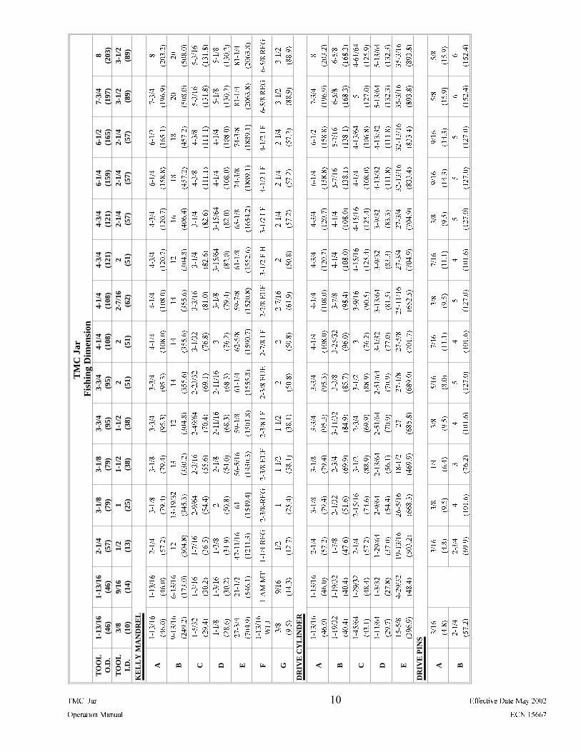
TMC JAR FISHING DIMENSIONS
Drive
Cylinder
Drive
Pins
A-Ring
Knocker
Kelly
Cylinder
Kelly
Mandrel
Detent
Mandrel
Neutralizer
Cylinder
Neutralizer
Piston
Washpipe
Cylinder
Detent
Cylinder
Detent Pin
Retainer Sub
TM
C J
arF
ishi
ng D
imen
sion
TO
OL
O.D
.1-
13/1
6(4
6)1-
13/1
6(4
6)2-
1/4
(57)
3-1/
8(7
9)3-
1/8
(79)
3-3/
4(9
5)3-
3/4
(95)
4-1/
4(1
08)
4-1/
4(1
08)
4-3/
4(1
21)
4-3/
4(1
21)
6-1/
4(1
59)
6-1/
2(1
65)
7-3/
4(1
97)
8(2
03)
TO
OL
I.D
.3/
8(1
0)9/
16(1
4)1/
2(1
3)1
(25)
1-1/
2(3
8)1-
1/2
(38)
2(5
1)2
(51)
2-7/
16(6
2)2
(51)
2-1/
4(5
7)2-
1/4
(57)
2-1/
4(5
7)3-
1/2
(89)
3-1/
2(8
9)K
EL
LY
MA
ND
RE
L
A1-13/16
1-13/16
2-1/4
3-1/8
3-1/8
3-3/4
3-3/4
4-1/4
4-1/4
4-3/4
4-3/4
6-1/4
6-1/2
7-3/4
8
(46.0)
(46.0)
(57.2)
(79.4)
(79.4)
(95.3)
(95.3)
(108.0)
(108.0)
(120.7)
(120.7)
(158.8)
(165.1)
(196.9)
(203.2)
B9-13/16
6-13/16
12
13-19/32
13
12
14
14
14
12
16
18
18
20
20
(249.2)
(173.0)
(304.8)
(345.3)
(330.2)
(304.8)
(355.6)
(355.6)
(355.6)
(304.8)
(406.4)
(457.2)
(457.2)
(508.0)
(508.0)
C1-5/32
1-3/16
1-7/16
2-9/64
2-3/16
2-49/64
2-23/32
3-1/32
3-3/16
3-1/4
3-1/4
4-3/8
4-3/8
5-3/16
5-3/16
(29.4)
(30.2)
(36.5)
(54.4)
(55.6)
(70.4)
(69.1)
(76.8)
(81.0)
(82.6)
(82.6)
(111.1)
(111.1)
(131.8)
(131.8)
D1-1/8
1-3/16
1-3/8
22-1/8
2-11/16
2-11/16
33-1/8
3-15/64
3-15/64
4-1/4
4-1/4
5-1/8
5-1/8
(28.6)
(30.2)
(34.9)
(50.8)
(54.0)
(68.3)
(68.3)
(76.2)
(79.4)
(82.0)
(82.0)
(108.0)
(108.0)
(130.2)
(130.2)
E27-3/4
21-1/2
47-11/16
61
56-5/16
59-1/8
61-1/4
62-5/8
59-7/8
61-1/8
65-1/8
74-3/8
74-3/8
81-1/4
81-1/4
(704.9)
(546.1)
(1211.3)
(1549.4)
(1430.3)
(1501.8)
(1555.8)
(1590.7)
(1520.8)
(1552.6)
(1654.2)
(1889.1)
(1889.1)
(2063.8)
(2063.8)
F1-13/16
WFJ
1AM
MT
1-1/4REG
2-3/8-REG
2-3/8EUE
2-3/8I.F.
2-3/8EUE
2-7/8I.F.
2-7/8EUE
3-1/2F.H.
3-1/2I.F.
4-1/2I.F.
4-1/2I.F.
6-5/8REG
6-5/8REG
G3/8
9/16
1/2
11-1/2
1-1/2
22
2-7/16
22-1/4
2-1/4
2-1/4
3-1/2
3-1/2
(9.5)
(14.3)
(12.7)
(25.4)
(38.1)
(38.1)
(50.8)
(50.8)
(61.9)
(50.8)
(57.2)
(57.2)
(57.2)
(88.9)
(88.9)
DR
IVE
CY
LIN
DE
R
A1-13/16
1-13/16
2-1/4
3-1/8
3-1/8
3-3/4
3-3/4
4-1/4
4-1/4
4-3/4
4-3/4
6-1/4
6-1/2
7-3/4
8
(46.0)
(46.0)
(57.2)
(79.4)
(79.4)
(95.3)
(95.3)
(108.0)
(108.0)
(120.7)
(120.7)
(158.8)
(158.8)
(196.9)
(203.2)
B1-19/32
1-19/32
1-7/8
2-1/32
2-3/4
3-11/32
3-3/8
3-25/32
3-7/8
4-1/4
4-1/4
5-7/16
5-7/16
6-5/8
6-5/8
(40.4)
(40.4)
(47.6)
(51.6)
(69.9)
(84.9)
(85.7)
(96.0)
(98.4)
(108.0)
(108.0)
(138.1)
(138.1)
(168.3)
(168.3)
C1-45/64
1-29/32
2-1/4
2-15/16
3-1/2
2-3/4
3-1/2
33-9/16
4-15/16
4-15/16
4-1/4
4-13/64
54-61/64
(43.1)
(48.4)
(57.2)
(74.6)
(88.9)
(69.9)
(88.9)
(76.2)
(90.5)
(125.4)
(125.4)
(108.0)
(106.8)
(127.0)
(125.9)
D1-11/64
1-3/32
1-29/64
2-9/64
2-13/64
2-51/64
2-51/64
3-1/32
3-13/64
3-9/32
3-9/32
4-13/32
4-13/32
5-13/64
5-13/64
(29.7)
(27.8)
(37.0)
(54.4)
(56.1)
(70.9)
(70.9)
(77.0)
(81.5)
(83.3)
(83.3)
(111.8)
(111.8)
(132.3)
(132.3)
E15-5/8
4-29/32
19-13/16
26-5/16
18-1/2
27
27-1/8
27-5/8
25-11/16
27-3/4
27-3/4
32-13/16
32-13/16
35-3/16
35-3/16
(396.9)
(48.4)
(503.2)
(668.3)
(469.9)
(685.8)
(689.0)
(701.7)
(652.5)
(704.9)
(704.9)
(833.4)
(833.4)
(893.8)
(893.8)
DR
IVE
PIN
S
A3/16
��
3/16
3/8
1/4
3/8
5/16
7/16
3/8
7/16
3/8
9/16
9/16
5/8
5/8
(4.8)
(4.8)
(9.5)
(6.4)
(9.5)
(8.0)
(11.1)
(9.5)
(11.1)
(9.5)
(14.3)
(14.3)
(15.9)
(15.9)
B2-1/4
2-3/4
43
45
45
45
55
66
(57.2)
(69.9)
(101.6)
(76.2)
(101.6)
(127.0)
(101.6)
(127.0)
(101.6)
(127.0)
(127.0)
(127.0)
(152.4)
(152.4)
TMC Jar 10 Effective Date May 2002
Operation Manual ECN 15667

TM
C J
arF
ishi
ng D
imen
sion
TO
OL
O.D
.1-
13/1
6(4
6)1-
13/1
6(4
6)2-
1/4
(57)
3-1/
8(7
9)3-
1/8
(79)
3-3/
4(9
5)3-
3/4
(95)
4-1/
4(1
08)
4-1/
4(1
08)
4-3/
4(1
21)
4-3/
4(1
21)
6-1/
4(1
59)
6-1/
2(1
65)
7-3/
4(1
97)
8(2
03)
TO
OL
I.D
.3/
8(1
0)9/
16(1
4)1/
2(1
3)1
(25)
1-1/
2(3
8)1-
1/2
(38)
2(5
1)2
(51)
2-7/
16(6
2)2
(51)
2-1/
4(5
7)2-
1/4
(57)
2-1/
4(5
7)3-
1/2
(89)
3-1/
2(8
9)D
RIV
E P
IN R
ET
AIN
ER
SU
B
A�
��
�3-1/8
��
��
��
��
��
(79.4)
B�
��
�2-3/4
��
��
��
��
��
(69.9)
C�
��
�3-1/2
��
��
��
��
��
(88.9)
D�
��
�7-13/16
��
��
��
��
��
(198.4)
E�
��
�2-49/64
��
��
��
��
��
(70.4)
F�
��
�2-9/64
��
��
��
��
��
(54.5)
A-R
ING
A23/32
�15/16
2-1/32
�1-3/16
11-1/2
1-5/32
1-5/8
1-5/8
1-3/8
1-3/8
1-15/16
115/16
(18.3)
(23.8)
(51.6)
(30.1)
(25.4)
(38.1)
(29.4)
(41.3)
(41.3)
(34.9)
(34.9)
(49.2)
(49.2)
B1-1/2
�1-3/4
2-5/8
�3-15/64
3-17/64
3-21/32
3-3/4
4-9/64
4-9/64
5-19/64
5-19/64
6-31/64
6-31/64
(38.1)
(44.5)
(66.7)
(82.1)
(82.8)
(93.0)
(95.3)
(105.0)
(105.0)
(134.6)
(134.6)
(164.6)
(164.6)
KN
OC
KE
R
A1-7/16
1-7/16
1-5/8
2-31/64
2-1/2
3-1/16
3-5/32
3-35/64
3-5/8
3-15/16
3-15/16
5-11/64
5-11/64
6-9/32
6-9/32
(36.5)
(36.5)
(41.3)
(63.2)
(63.5)
(77.8)
(80.2)
(90.3)
(92.1)
(100.0)
(100.0)
(131.3)
(131.3)
(159.7)
(159.7)
B3-17/32
4-5/32
5-3/16
6-1/4
6-1/2
5-7/8
6-1/4
7-1/8
67-3/8
7-3/8
8-3/4
8-3/4
10-3/4
10-3/4
(89.7)
(105.6)
(131.8)
(158.8)
(165.1)
(149.2)
(158.8)
(181.0)
(152.4)
(187.3)
(187.3)
(222.3)
(222.3)
(273.1)
(273.1)
C63/64
11-15/64
1-29/32
2-1/32
2-37/64
2-37/64
2-29/32
3-1/64
3-5/32
3-5/32
4-3/64
4-3/64
4-59/64
4-59/64
(25.0)
(25.4)
(31.5)
(48.4)
(51.4)
(65.7)
(65.7)
(73.8)
(76.7)
(80.0)
(80.0)
(102.9)
(102.9)
(125.1)
(125.1)
D29/64
51/64
55/64
1-21/64
1-13/16
2-1/32
2-13/32
2-13/32
2-29/32
2-13/32
2-21/32
3-1/32
3-1/32
4-19/64
4-19/64
(15.5)
(20.2)
(22.0)
(34.0)
(46.0)
(51.4)
(61.0)
(61.0)
(73.8)
(61.0)
(67.3)
(76.8)
(76.8)
(109.2)
(109.2)
E3/8
9/16
1/2
11-1/2
1-1/2
22
2-7/16
22-1/4
2-1/4
2-1/4
3-1/2
3-1/2
(9.5)
(14.3)
(12.7)
(25.4)
(38.1)
(38.1)
(50.8)
(50.8)
(61.9)
(50.8)
(57.2)
(57.2)
(57.2)
(88.9)
(88.9)
F1-39/32
1-21/32
2-5/16
33
2-7/8
3-1/8
3-1/2
2-7/8
3-3/4
3-3/4
4-1/8
4-1/8
66
(48.4)
(42.1)
(58.7)
(76.2)
(76.2)
(73.0)
(79.4)
(88.9)
(73.0)
(95.3)
(95.3)
(104.8)
(104.8)
(152.4)
(152.4)
H1-7/16
1-7/16
2-7/16
2-3/4
2-15/16
2-1/2
2-3/8
32-5/8
33
44
44
(36.5)
(36.5)
(61.9)
(69.9)
(74.6)
(63.5)
(60.3)
(76.2)
(66.7)
(76.2)
(76.2)
(101.6)
(101.6)
(101.6)
(101.6)
Effective Date May 2002 11 TMC Jar
ECN 15567 Operation Manual

TM
C J
arF
ishi
ng D
imen
sion
TO
OL
O.D
.1-
13/1
6(4
6)1-
13/1
6(4
6)2-
1/4
(57)
3-1/
8(7
9)3-
1/8
(79)
3-3/
4(9
5)3-
3/4
(95)
4-1/
4(1
08)
4-1/
4(1
08)
4-3/
4(1
21)
4-3/
4(1
21)
6-1/
4(1
59)
6-1/
2(1
65)
7-3/
4(1
97)
8(2
03)
TO
OL
I.D
.3/
8(1
0)9/
16(1
4)1/
2(1
3)1
(25)
1-1/
2(3
8)1-
1/2
(38)
2(5
1)2
(51)
2-7/
16(6
2)2
(51)
2-1/
4(5
7)2-
1/4
(57)
2-1/
4(5
7)3-
1/2
(89)
3-1/
2(8
9)K
EL
LY
CY
LIN
DE
R
A1-13/16
1-13/16
2-1/4
3-1/8
3-1/8
3-3/4
3-3/4
4-1/4
4-1/4
4-3/4
4-3/4
6-1/4
6-1/2
7-3/4
8
(46.0)
(46.1)
(57.2)
(79.4)
(79.4)
(95.6)
(95.3)
(108.0)
(108.0)
(120.7)
(120.7)
(158.8)
(165.1)
(196.9)
(203.2)
B1-1/2
1-1/2
1-3/4
2-33/64
2-9/16
3-5/32
3-3/16
3-37/64
3-41/64
44
5-1/4
5-1/4
6-5/16
6-5/16
(38.1)
(38.1)
(44.5)
(63.8)
(65.1)
(80.2)
(81.0)
(90.9)
(92.6)
(101.6)
(101.6)
(133.4)
(133.4)
(160.4)
(160.4)
C21-3/8
17-1/32
28-1/8
36-3/4
31-5/16
36-5/8
35-1/8
38-7/16
35-5/16
41-3/8
41-3/8
44-3/4
44-3/4
50-7/8
50-7/8
(542.9)
(432.6)
(714.4)
(933.5)
(795.3)
(930.3)
(892.2)
(976.3)
(897.0)
(1050.9)
(1050.9)
(1136.7)
(1136.7)
(1292.2)
(1292.2)
DE
TE
NT
CY
LIN
DE
R
A1-13/16
1-13/16
2-1/4
3-1/8
3-1/8
3-3/4
3-3/4
4-1/4
4-1/4
4-3/4
4-3/4
6-1/4
6-1/2
7-3/4
8
(46.0)
(46.1)
(57.2)
(79.4)
(79.4)
(95.25)
(95.3)
(108.0)
(108.0)
(120.7)
(120.7)
(158.75)
(165.1)
(196.9)
(203.2)
B1-19/32
1-19/32
1-3/4
2-5/8
2-3/4
3-5/16
3-5/16
3-3/4
3-3/4
4-1/8
4-1/8
5-7/16
5-7/16
6-5/8
6-5/8
(40.4)
(40.5)
(44.5)
(66.7)
(69.9)
(84.2)
(84.2)
(95.3)
(95.3)
(104.8)
(104.8)
(138.1)
(138.1)
(168.3)
(168.3)
C49/64
15/16
1-1/64
1-33/64
1-61/64
2-9/64
2-17/32
2-17/32
3-1/32
2-17/32
2-53/64
3-17/64
3-17/64
4-35/64
4-35/64
(19.6)
(23.6)
(25.8)
(38.4)
(49.7)
(54.5)
(64.3)
(64.3)
(77.0)
(64.3)
(72.0)
(83.1)
(83.1)
(115.6)
(115.6)
D2-5/16
2-27/32
34-13/64
3-1/2
43-1/2
4-1/2
3-1/2
4-11/16
4-11/16
4-15/16
4-57/64
5-7/8
5-53/64
(58.8)
(72.2)
(76.2)
(106.7)
(88.9)
(101.6)
(88.9)
(114.3)
(88.9)
(119.1)
(119.1)
(125.4)
(124.2)
(149.2)
(148.1)
E15-3/16
13-1/2
22-3/8
28-13/32
25-5/8
26
27-1/4
29
27-1/4
28-3/16
28-3/16
32-13/16
32-55/64
32-1/4
32-19/64
(385.8)
(342.9)
(568.3)
(721.5)
(650.9)
(660.4)
(692.2)
(736.6)
(692.2)
(715.9)
(715.9)
(833.5)
(834.6)
(819.2)
(820.3)
DE
TE
NT
MA
ND
RE
L
A11/16
1-1/16
15/16
1-7/16
1-29/32
2-1/8
2-1/2
2-1/2
32-1/2
2-3/4
3-1/8
3-1/8
4-1/2
4-1/2
(17.5)
(27.0)
(23.8)
(36.5)
(48.5)
(54.0)
(63.5)
(63.5)
(76.2)
(63.5)
(69.9)
(79.4)
(79.4)
(114.3)
(114.3)
B3/8
9/16
1/2
11-1/2
1-1/2
22
2-7/16
22-1/4
2-1/4
2-1/4
3-1/2
3-1/2
(9.5)
(14.3)
(12.7)
(25.4)
(38.1)
(38.1)
(50.8)
(50.8)
(61.9)
(50.8)
(57.2)
(57.2)
(57.2)
(88.9)
(88.9)
C3/4
29/32
11-1/2
1-15/16
2-9/64
2-33/64
2-33/64
3-1/32
2-33/64
2-13/16
3-1/4
3-1/4
4-17/32
4-17/32
(19.1)
(23.0)
(25.4)
(38.1)
(49.2)
(54.2)
(64.0)
(64.0)
(76.8)
(64.0)
(71.5)
(82.6)
(82.6)
(115.1)
(115.1)
D18-7/32
13-7/8
29-1/16
32-1/8
27-11/16
31-7/16
30-3/4
33
30-9/16
33
33
38-1/8
38-1/8
40-1/4
40-1/4
(462.8)
(352.4)
(738.2)
(816.0)
(703.3)
(798.5)
(781.1)
(838.2)
(776.3)
(838.2)
(838.2)
(968.4)
(968.4)
(1022.4)
(1022.4)
E1-19/32
1-5/8
1-7/8
3-5/8
3-1/8
2-11/16
2-3/8
3-1/2
2-9/16
3-1/2
3-1/2
4-1/8
4-1/8
3-1/2
3-1/2
(40.5)
(41.3)
(47.6)
(92.1)
(79.4)
(68.3)
(60.3)
(88.9)
(65.1)
(88.9)
(88.9)
(104.8)
(104.8)
(88.9)
(88.9)
F3/8
3/8
3/4
11/16
15/16
3/4
11
11
11-1/4
1-1/4
11
(9.5)
(9.5)
(19.1)
(17.5)
(23.8)
(19.1)
(25.4)
(25.4)
(25.40)
(25.4)
(25.4)
(31.8)
(31.8)
(25.4)
(25.4)
G27-7/16
17-3/4
31
39-5/8
32
41
36-1/2
41-15/16
36-3/8
41-15/16
41-9/16
44-1/8
44-1/8
45-3/4
45-3/4
(696.9)
(450.9)
(787.4)
(1006.5)
(812.8)
(1041.4)
(923.1)
(1065.2)
(923.9)
(1065.2)
(1055.7)
(1120.8)
(1120.8)
(1162.1)
(1162.1)
TMC Jar 12 Effective Date May 2002Operation Manual ECN 15667

TM
C J
arF
ishi
ng D
imen
sion
TO
OL
O.D
.1-
13/1
6(4
6)1-
13/1
6(4
6)2-
1/4
(57)
3-1/
8(7
9)3-
1/8
(79)
3-3/
4(9
5)3-
3/4
(95)
4-1/
4(1
08)
4-1/
4(1
08)
4-3/
4(1
21)
4-3/
4(1
21)
6-1/
4(1
59)
6-1/
2(1
65)
7-3/
4(1
97)
8(2
03)
TO
OL
I.D
.3/
8(1
0)9/
16(1
4)1/
2(1
3)1
(25)
1-1/
2(3
8)1-
1/2
(38)
2(5
1)2
(51)
2-7/
16(6
2)2
(51)
2-1/
4(5
7)2-
1/4
(57)
2-1/
4(5
7)3-
1/2
(89)
3-1/
2(8
9)
H1-1/4
25/64
1-9/16
2-1/4
2-1/2
2-7/8
3-3/32
3-3/8
3-1/2
3-3/8
3-3/4
4-3/4
4-3/4
6-1/8
6-1/8
(31.8)
(35.3)
(39.7)
(57.2)
(63.5)
(73.0)
(78.6)
(85.7)
(88.9)
(85.7)
(95.3)
(120.7)
(120.7)
(155.6)
(155.6)
I3/4
29/32
11-1/2
1-15/16
2-9/64
2-33/64
2-33/64
3-1/32
2-33/64
2-13/16
3-1/4
3-1/4
4-17/32
4-17/32
(19.1)
(23.0)
(25.4)
(38.1)
(49.2)
(54.2)
(64.0)
(64.0)
(76.8)
(64.0)
(71.5)
(82.6)
(82.6)
(115.1)
(115.1)
NE
UT
RA
LIZ
ER
CY
LIN
DE
R
A1-19/32
1-19/32
1-3/4
2-5/8
2-3/4
3-5/16
3-5/16
3-3/4
3-3/4
4-1/8
4-1/8
5-7/16
5-7/16
6-5/8
6-5/8
(40.4)
(40.4)
(44.5)
(66.7)
(69.9)
(84.2)
(84.2)
(95.3)
(95.3)
(104.8)
(104.8)
(138.1)
(138.1)
(168.3)
(168.3)
B13/16
63/64
1-1/8
1-5/8
2-1/8
2-1/4
2-9/16
2-5/8
3-3/32
2-3/4
33-3/4
3-3/4
4-3/4
4-3/4
(20.6)
(24.8)
(28.6)
(41.3)
(54.0)
(57.2)
(65.1)
(66.7)
(78.6)
(69.9)
(76.2)
(95.3)
(95.3)
(120.7)
(120.7)
C1-13/16
1-13/16
2-1/4
3-1/8
3-1/8
3-3/4
3-3/4
4-1/4
4-1/4
4-3/4
4-3/4
6-1/4
6-1/2
7-3/4
8
(46.0)
(46.1)
(57.2)
(79.4)
(79.4)
(95.3)
(95.3)
(108.0)
(108.0)
(120.7)
(120.7)
(158.8)
(165.1)
(196.9)
(203.2)
D13-3/8
912-19/32
17-39/64
12-1/2
18-3/8
15
19-1/2
15-1/8
19-3/4
19-3/4
18-45/64
18-3/4
19-1/4
19-19/64
(339.7)
(228.6)
(319.9)
(447.3)
(317.5)
(466.7)
(381.0)
(495.3)
(384.2)
(501.7)
(501.7)
(475.0)
(476.2)
(483.0)
(490.1)
E1-7/8
2-1/2
33-25/64
3-1/2
3-3/4
3-1/2
4-1/4
3-1/2
44
4-19/64
4-1/4
54-61/64
(47.6)
(63.5)
(76.2)
(86.1)
(88.9)
(95.3)
(88.9)
(108.0)
(88.9)
(101.6)
(101.6)
(109.2)
(108.1)
(127.0)
(125.9)
F1-3/8
1-29/64
1-5/8
2-1/2
2-9/16
3-3/16
3-1/8
3-5/8
3-5/8
44
5-1/4
5-1/4
6-3/8
6-3/8
(34.9)
(36.8)
(41.3)
(63.5)
(65.1)
(81.0)
(79.4)
(92.1)
(92.1)
(101.6)
(101.6)
(133.4)
(133.6)
(161.9)
(161.9)
NE
UT
RA
LIZ
ER
PIS
TO
N
A1-23/64
1-13/32
1-39/64
2-31/64
2-35/64
3-11/64
3-7/64
3-39/64
3-39/64
3-63/64
3-63/64
5-15/64
5-15/64
6-23/64
6-23/64
(34.4)
(35.8)
(40.8)
(63.0)
(64.6)
(80.5)
(79.0)
(91.8)
(91.8)
(101.1)
(101.3)
(133.1)
(133.1)
(161.4)
(161.4)
B2-1/2
23
3-1/4
2-7/16
2-7/8
2-1/2
42-1/2
44
44
44
(63.5)
(50.8)
(76.2)
(82.6)
(61.9)
(73.0)
(63.5)
(101.6)
(63.5)
(101.6)
(101.6)
(101.6)
(101.6)
(101.6)
(101.6)
C49/64
59/64
1-1/64
1-33/64
1-61/64
2-9/64
2-17/32
2-17/32
3-1/32
2-17/32
2-27/32
3-17/64
3-17/64
4-35/64
4-35/64
(19.6)
(23.5)
(25.8)
(38.4)
(49.7)
(54.5)
(64.2)
(64.3)
(77.1)
(64.3)
(72.0)
(83.1)
(83.1)
(115.6)
(115.6)
Effective Date May 2002 13 TMC Jar
ECN 15667 Operation Manual

TM
C J
arF
ishi
ng D
imen
sion
TO
OL
O.D
.1-
13/1
6(4
6)1-
13/1
6(4
6)2-
1/4
(57)
3-1/
8(7
9)3-
1/8
(79)
3-3/
4(9
5)3-
3/4
(95)
4-1/
4(1
08)
4-1/
4(1
08)
4-3/
4(1
21)
4-3/
4(1
21)
6-1/
4(1
59)
6-1/
2(1
65)
7-3/
4(1
97)
8(2
03)
TO
OL
I.D
.3/
8(1
0)9/
16(1
4)1/
2(1
3)1
(25)
1-1/
2(3
8)1-
1/2
(38)
2(5
1)2
(51)
2-7/
16(6
2)2
(51)
2-1/
4(5
7)2-
1/4
(57)
2-1/
4(5
7)3-
1/2
(89)
3-1/
2(8
9)W
ASH
PIP
E C
YL
IND
ER
A1-19/32
1-19/32
1-3/4
2-5/8
2-3/4
3-5/16
3-5/16
3-3/4
3-3/4
4-1/8
4-1/8
5-7/16
5-7/16
6-5/8
6-5/8
(40.4)
(40.4)
(44.5)
(66.7)
(69.9)
(84.2)
(84.2)
(95.3)
(95.3)
(104.8)
(104.8)
(138.1)
(138.1)
(168.3)
(168.3)
B19-13/16
8-1/8
27.0
29-5/8
29-15/16
32-3/4
32-1/2
29-3/4
31
31-13/16
35-13/16
36-61/64
37
39
39-3/64
(503.2)
(206.4)
(685.8)
(752.5)
(760.1)
(831.9)
(825.5)
(755.6)
(787.4)
(808.0)
(909.6)
(938.5)
(939.8)
(990.6)
(991.7)
C1-13/16
1-13/16
2-1/4
3-1/8
3-1/8
3-3/4
3-3/4
4-1/4
4-1/4
4-3/4
4-3/4
6-1/4
6-1/2
7-3/4
8
(46.0)
(46.1)
(57.2)
(79.4)
(79.4)
(95.3)
(95.3)
(108.0)
(108.0)
(120.7)
(120.7)
(158.8)
(165.1)
(196.9)
(203.2)
D3/8
9/16
1/2
11-1/2
1-1/2
22
2-7/16
22-1/4
2-1/4
2-1/4
3-1/2
3-1/2
(9.5)
(14.3)
(12.7)
(25.4)
(38.1)
(38.1)
(50.8)
(50.8)
(61.9)
(50.8)
(57.2)
(57.15)
(57.2)
(88.9)
(88.9)
E13/16
1-1/32
1-1/8
1-5/8
22-5/16
2-9/16
2-5/8
3-1/8
2-19/32
2-15/16
3-7/16
3-7/16
4-11/16
4-11/16
(20.6)
(26.2)
(28.6)
(41.3)
(50.8)
(58.7)
(65.1)
(66.7)
(79.4)
(65.9)
(74.6)
(87.3)
(87.3)
(119.1)
(119.1)
F1-15/16
3-7/32
33-25/64
3-1/2
3-3/4
3-1/2
4-1/4
3-1/2
4-11/16
4-1/2
4-19/64
4-1/4
54-61/64
(49.2)
(81.8)
(76.2)
(86.1)
(88.9)
(95.3)
(88.9)
(108.0)
(88.9)
(199.1)
(114.3)
(109.2)
(108.1)
(127.0)
(125.9)
G49/64
15/16
1-1/64
1-33/64
1-61/64
2-9/64
2-17/32
2-17/32
3-1/32
2-17/32
2-53/64
3-17/64
3-17/64
4-35/64
4-35/64
(19.6)
(23.6)
(25.8)
(39.4)
(49.7)
(54.5)
(64.2)
(64.3)
(77.0)
(64.3)
(72.0)
(83.1)
(83.1)
(115.6)
(115.6)
TMC Jar 14 Effective Date May 2002Operation Manual ECN 15667


P.O.Box 60068 • Houston, Texas 77205-0068 U.S. and Canada: 800-US Smith Tel: 281-443-3370 • Fax: 281-233-5121 www.smith.com ©2007 Smith International, Inc. All Rights Reserved. Litho in U.S.A.


