
Technical Data Sheet
High Performance, Broadband Network Analysis Solutions
ME7838AX — 2-Port Series Vector Network AnalyzersME7838A4X — 4-Port Series Vector Network AnalyzersBroadband VNA System 70 kHz to 125 GHz Millimeter Waveguide VNA System 50 GHz to 1.1 THz
TM

VectorStar Technical Data
2 of 26 PN: 11410-02825 Rev. A ME7838AX/A4X VNA TDS
ME7838AX/A4X VNA Introduction
A detailed color brochure available on the Anritsu web site provides descriptions and examples of the VectorStar family’s features and benefits:
https://www.anritsu.com/test-measurement/products/ms4640b-series
ME7838AX 2-Port Broadband VNA System 70 kHz to 125 GHz The ME7838AX broadband configuration provides single sweep coverage from 70 kHz to 125 GHz. It consists of the following items:• MS4647B VectorStar™ VNA, 70 kHz to 70 GHz with Option 7, Option 70, and Option 80/81 or Option 84/85• 3739C Broadband mmWave Test Set and Interface Cables• 3743AX Broadband mmWave modules, 2 each
ME7838AX 2-Port Millimeter Waveguide VNA System 50 GHz to 1.1 THz The ME7838AX mmWave configuration provides waveguide output from 50 GHz to 1.1 THz in waveguide bands. The system can extend the broadband system or be configured to operate only as a waveguide system. It consists of the following items:• MS464xB VectorStar VNA, with Option 7 and Option 82/83 or Option 84/85• 3739C Broadband/mmWave Test Set and Interface Cables• mmWave modules, 2 each
ME7838A4X 4-Port Broadband VNA System 70 kHz to 125 GHz The VectorStar ME783A4X system is similar to the ME7838AX system, except it is configured for 4-port measurements.It consists of: • MS4647B VectorStar VNA, 70 kHz to 70 GHz with Option 7, Option 70, and Option 81/85• 3739C Broadband mmWave Test Set and Interface Cables• 3743AX Broadband mmWave modules, 4 each• 3736B Broadband mmWave Test Set and Interface Cables• MN4697C Four Port Test Set and Interface cables
ME7838A4X 4-Port Millimeter Waveguide VNA System 50 GHz to 1.1 THz The ME7838A4X mmWave configuration provides waveguide output from 50 GHz to 1.1 THz in waveguide bands. The system can extend the broadband system or be configured to operate only as a waveguide system. It consists of the following items:• MS4647B VectorStar VNA, 70 kHz to 70 GHz with Option 7, and Option 83/85• 3739C Broadband mmWave Test Set and Interface Cables• mmWave modules, 4 each• 3736B Broadband mmWave Test Set and Interface Cables• MN4697C Four Port Test Set and Interface cables
A detailed color brochure available on the Anritsu web site provides descriptions and examples of the VectorStar family’s features and benefits:
https://www.anritsu.com/test-measurement/products/ms4640b-series
• Industry-best broadband frequency coverage – starts at 70 kHz instead of 10 MHz and is operational from 40 kHz to 125 GHz.
• Industry-best calibration and measurement stability – 0.1 dB vs 0.6 dB over 24 hrs.
• Industry-best compact, lightweight mmWave modules for easy, precise, and economical positioning on the wafer probe station – 0.6 vs 7.6 lb and 1/50 the volume.
• Thin film multipliers, receivers, and couplers at the test port, offering best raw directivity and providing excellent calibration and measurement stability.
• The industry’s only available mmWave real time electronic power leveling – eliminates time-lagging software correction tables.
• Compatibility with all major probe stations.• Kelvin bias tees for sense and force capabilities closely
positioned to the DUT. • Can be upgraded to a 4-port 145 GHz version with the
addition of MA25300A modules.

Specifications ME7838AX/A4X VNA
ME7838AX/A4X VNA TDS PN: 11410-02825 Rev. A 3 of 66
Table of Contents
ME7838AX/A4X VNA IntroductionDefinitions. . . . . . . . . . . . . . . . . . . . . . . . . . . . . . . . . . . . . . . . . . . . . . . . . . . . . . . . . . . . . . . . . . . . . . . . . . . . . . . . . . . . . 4Broadband Configuration . . . . . . . . . . . . . . . . . . . . . . . . . . . . . . . . . . . . . . . . . . . . . . . . . . . . . . . . . . . . . . . . . . . . . . . 5
ME7838AX 2-Port VNADynamic Range Specifications. . . . . . . . . . . . . . . . . . . . . . . . . . . . . . . . . . . . . . . . . . . . . . . . . . . . . . . . . . . . . . . . . . . . 9Power Specifications . . . . . . . . . . . . . . . . . . . . . . . . . . . . . . . . . . . . . . . . . . . . . . . . . . . . . . . . . . . . . . . . . . . . . . . . . . .10Corrected System Performance and Uncertainties . . . . . . . . . . . . . . . . . . . . . . . . . . . . . . . . . . . . . . . . . . . . . . . . .15Broadband Measurement Examples . . . . . . . . . . . . . . . . . . . . . . . . . . . . . . . . . . . . . . . . . . . . . . . . . . . . . . . . . . . . .18
ME7838A4X 4-Port VNADynamic Range Specifications. . . . . . . . . . . . . . . . . . . . . . . . . . . . . . . . . . . . . . . . . . . . . . . . . . . . . . . . . . . . . . . . . . .26Power Specifications . . . . . . . . . . . . . . . . . . . . . . . . . . . . . . . . . . . . . . . . . . . . . . . . . . . . . . . . . . . . . . . . . . . . . . . . . . .27Corrected System Performance and Uncertainties . . . . . . . . . . . . . . . . . . . . . . . . . . . . . . . . . . . . . . . . . . . . . . . . .32Measurement Examples. . . . . . . . . . . . . . . . . . . . . . . . . . . . . . . . . . . . . . . . . . . . . . . . . . . . . . . . . . . . . . . . . . . . . . . .35
AccessoriesWaveguide Band Configuration . . . . . . . . . . . . . . . . . . . . . . . . . . . . . . . . . . . . . . . . . . . . . . . . . . . . . . . . . . . . . . . . .39Waveguide Band Specifications . . . . . . . . . . . . . . . . . . . . . . . . . . . . . . . . . . . . . . . . . . . . . . . . . . . . . . . . . . . . . . . . .40mmWave Noise Figure Measurements with Option 41/48 and 3744A-Rx . . . . . . . . . . . . . . . . . . . . . . . . . . . . . .45Waveguide Bands from 50 GHz to 1.1 THz . . . . . . . . . . . . . . . . . . . . . . . . . . . . . . . . . . . . . . . . . . . . . . . . . . . . . . . .46
Standard Capabilities for All ConfigurationsMechanical and Environmental . . . . . . . . . . . . . . . . . . . . . . . . . . . . . . . . . . . . . . . . . . . . . . . . . . . . . . . . . . . . . . . . . .51Regulatory Compliance. . . . . . . . . . . . . . . . . . . . . . . . . . . . . . . . . . . . . . . . . . . . . . . . . . . . . . . . . . . . . . . . . . . . . . . . .51Warranty . . . . . . . . . . . . . . . . . . . . . . . . . . . . . . . . . . . . . . . . . . . . . . . . . . . . . . . . . . . . . . . . . . . . . . . . . . . . . . . . . . . . .52Calibration and Correction Capabilities . . . . . . . . . . . . . . . . . . . . . . . . . . . . . . . . . . . . . . . . . . . . . . . . . . . . . . . . . . .53Mechanical Calibration/Verification Kits . . . . . . . . . . . . . . . . . . . . . . . . . . . . . . . . . . . . . . . . . . . . . . . . . . . . . . . . . .54Test Port Cables . . . . . . . . . . . . . . . . . . . . . . . . . . . . . . . . . . . . . . . . . . . . . . . . . . . . . . . . . . . . . . . . . . . . . . . . . . . . . . .55Precision Adapters, Attenuators, and Other Components . . . . . . . . . . . . . . . . . . . . . . . . . . . . . . . . . . . . . . . . . . .56ME7838AX Ordering Information . . . . . . . . . . . . . . . . . . . . . . . . . . . . . . . . . . . . . . . . . . . . . . . . . . . . . . . . . . . . . . . .57ME7838A4X Ordering Information . . . . . . . . . . . . . . . . . . . . . . . . . . . . . . . . . . . . . . . . . . . . . . . . . . . . . . . . . . . . . . .60Calibration and Verification Kits Ordering Information . . . . . . . . . . . . . . . . . . . . . . . . . . . . . . . . . . . . . . . . . . . . .62

ME7838AX/A4X VNA Specifications
4 of 66 PN: 11410-02825 Rev. A ME7838AX/A4X VNA TDS
Definitions All specifications and characteristics apply under the following conditions, unless otherwise stated. Warm-Up Time After 90 minutes of warm-up time, where the instrument is left in the ON state.
Temperature Range Over the 25 °C ± 5 °C temperature range. Error-Corrected Specifications For error-corrected specifications, over 23 °C ± 3 °C, with < 1 °C variation from calibration temperature.
For error-corrected specifications are warranted and include guard bands, unless otherwise stated. Typical Performance “Typical” specifications describe expected, but not warranted, performance based on sample testing. Typical
performance indicates the measured performance of an average unit and do not guarantee the performance of any individual product. “Typical” specifications do not account for measurement uncertainty and are shown in parenthesis, such as (-102 dB), or noted as Typical.
User Cables/Adapters Specifications do not include effects of any user cables, adapters, fixtures or other structures attached to the instrument.
Discrete Spurious Responses Specifications may exclude discrete spurious responses. Internal Reference Signal All specifications apply with internal 10 MHz Crystal Oscillator Reference Signal.
Characteristic Performance Characteristic performance indicates a performance designed-in and verified during the design phase. It does include guard-bands and is not covered by the product warranty.
Below 300 kHz All uncertainties below 300 kHz are typical. Recommended Calibration Cycle 12 months
Interpolation Mode All specifications are with Interpolation Mode Off.Specifications Subject to Change All specifications subject to change without notice. For the most current data sheet, please visit the Anritsu
web site at www.anritsu.com.
The instrument may be protected by one or more of the following patents: 6894581, 7088111, 7545151, 7683633, 7924024, 8185078, 8306134, 8417189, 8718586, 9103873, 9606212, 9753071, 10225073, 10778592, 10225073 depending on the model and option configuration of the instrument.
Specifications ME7838AX/A4X VNA
ME7838AX/A4X VNA TDS PN: 11410-02825 Rev. A 5 of 66
Broadband Configuration Broadband Specifications and Performance
ME7838AX 2-port Broadband Hardware Configuration The ME7838AX 2-port broadband VNA system provides single sweep coverage from 70 kHz to 125 GHz and is operational from 40 kHz to 125 GHz.It consists of the following items:
VNA MS4647B VectorStar VNA, 70 kHz to 70 GHz with Option 7, Option 70, and Option 80/81/84/85Broadband Test Set 3739C Broadband Test Set and interface cablesmmWave Modules 3743AX Broadband mmWave modules (2 Each)
ME7838A4X 4-Port Broadband Hardware Configuration The ME7838A4X 4-port broadband VNA system provides single sweep coverage from 70 kHz to 125 GHz and is operational from 40 kHz to 125 GHz. It consists of the following items:
Broadband VNA ME7838AX Broadband VNA System with Option 51, 61, or 624-Port Test Set MN4697C 2U 4-Port Test Set
mmWave Modules 3743AX mmWave Modules, 2 each (two incremental to the modules in the ME7838AX)Test Set 3736B Broadband Test Set with Cables
ME7838AX/A4X VNA Broadband/mmWave System Options The major ME7838AX/A4X VNA broadband VNA system options are:
Option 02 MS4640B-002 – Time DomainOption 21 MS4640B-021 – Universal Fixture ExtractionOption 31 MS464xB-031 – Dual Source Architecture Option 32 MS464xB-032 – Internal RF CombinerOption 35 MS4640B-035 – IF DigitizerOption 36 MS4640B-036 – Extended IF Digitizer MemoryOption 41 MS4640B-041 – Noise FigureOption 42 MS4640B-042 – PulseView™Option 43 MS4640B-043 – DifferentialView™Option 44 MS4640B-044 – IMDView™Option 46 MS4640B-046 – Fast CWOption 47 MS4640B-047 – Eye DiagramOption 48 MS4640B-048 – Differential Noise FigureOption 51 MS464xB-051 – External VNA Direct Access LoopsOption 61 MS464xB-061 – Active Measurement Suite, with 2 AttenuatorsOption 62 MS464xB-062 – Active Measurement Suite, with 4 AttenuatorsBias Tees SC8215 and SC7287 – Kelvin Bias Tees
ME7838AX/A4X VNA Specifications
6 of 66 PN: 11410-02825 Rev. A ME7838AX/A4X VNA TDS
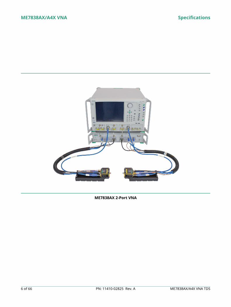
ME7838AX 2-Port VNA
A A

Specifications ME7838AX/A4X VNA
ME7838AX/A4X VNA TDS PN: 11410-02825 Rev. A 7 of 66
ME7838AX 2-port Broadband System
20-40 GHz5 dBm
RF
5-10 GHz5 dBm
LO1
5-10 GHz5 dBm
LO2
VectorStar MS4647B VNA with Option 08x
Model 3739C Broadband Test Set
RF
W1 Test Ports
LO1 LO2
3743AX mmWaveModule
3743AX mmWaveModule
LO to
RCV
R5-
10 G
Hz
ALC
Pw
r & C
ontr
ol
ALC
Pw
r & C
ontr
ol
Ref I
F
RF to
Mul
tiplie
rs20
-40
GH
z
Test
IF
TP1 TP2
P1 R
F O
ut 7
0 kH
z to
54
GH
z
P2 R
F O
ut 7
0 kH
z to
54
GH
z
LO to
RCV
R5-
10 G
Hz
EXT
ALC
Inpu
t to
VNA
Four
Ext
erna
l IF
Inpu
ts to
VN
AEx
tern
al I/
O fr
om V
NA
Ana
log
Out
put f
rom
VN
A
Ref I
F
RF to
Mul
tiplie
rs20
-40
GH
z
Test
IF
ME7838AX/A4X VNA Specifications
8 of 66 PN: 11410-02825 Rev. A ME7838AX/A4X VNA TDS
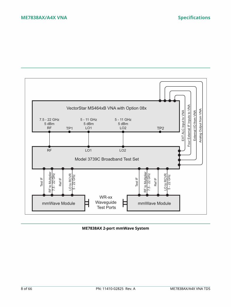
ME7838AX 2-port mmWave System
7.5 - 22 GHz5 dBm
RF
5 - 11 GHz5 dBmLO1
5 - 11 GHz5 dBmLO2
VectorStar MS464xB VNA with Option 08x
Model 3739C Broadband Test Set
RF
Test
IF
RF
to M
ultip
lier
7.5
- 22
GH
z
Ref
IF
LO to
RC
VR
5 - 2
2 G
Hz
WR-xxWaveguide Test Ports
LO1
TP1 TP2
LO2
mmWave Module mmWave Module
Test
IF
RF
to M
ultip
lier
7.5
- 22
GH
z
Ref
IF
LO to
RC
VR
5 - 2
2 G
Hz
EX
T A
LC In
put t
o V
NA
Four
Ext
erna
l IF
Inpu
ts to
VN
A
Ext
erna
l I/O
from
VN
A
Ana
log
Out
put f
rom
VN
A

Specifications ME7838AX/A4X VNA
ME7838AX/A4X VNA TDS PN: 11410-02825 Rev. A 9 of 66
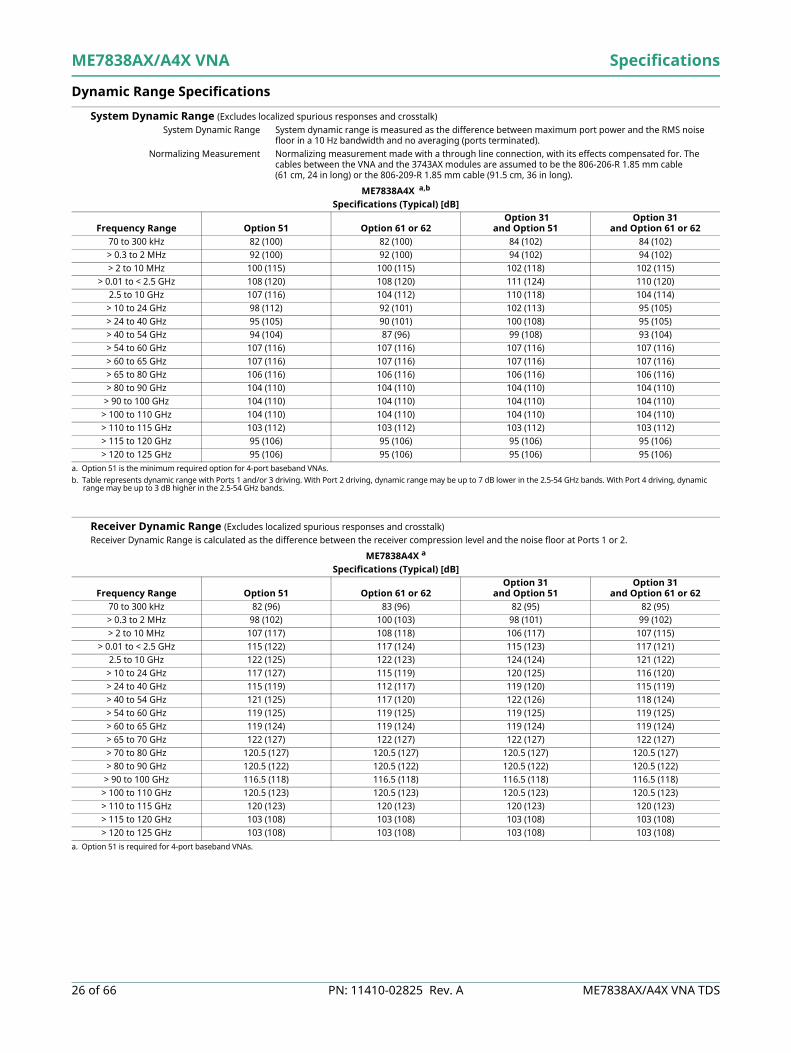
Dynamic Range Specifications
System Dynamic Range (Excludes localized spurious responses and crosstalk)System Dynamic Range is measured as the difference between maximum port power and the RMS noise floor in a 10 Hz bandwidth and no averaging (ports terminated).Normalizing Measurement is made with a through line connection, with its effects compensated for. The cables between the VNA and the 3743AX modules are assumed to be the 806-206-R 1.85 mm cable (61 cm, 24 in long) or the 806-209-R 1.85 mm cable (91.5 cm, 36 in long).
Receiver Dynamic Range (Excludes localized spurious responses and crosstalk)Calculated as the difference between the receiver compression level and the noise floor at Ports 1 or 2.Normalizing measurement is made with a through line connection, with its effects compensated for. The cables between the VNA and the 3743AX modules are assumed to be the 806-206-R 1.85 mm cable (61 cm, 24 in long) or the 806-209-R 1.85 mm cable (91.5 cm, 36 in long).
ME7838AX a
a. Excludes localized spurious responses and crosstalk.
Specifications (Typical) [dB]
Frequency Range No Options Option 51 b
b. Also ME7838AX Option 61, S12 values.
Option 61 or 62 Option 31 c
c. Values shown are for port 1. For port 2, the dynamic range is degraded by 2 dB at low frequency to 5 dB at 54 GHz (typical). Frequencies above 54 GHz are unaffected.
Option 31 b,c
and Option 51Option 31 c and Option 61 or 62
70 to 300 kHz 95 (110) 95 (110) 95 (108) 97 (112) 97 (112) 97 (110)> 0.3 to 2 MHz 107 (120) 107 (120) 107 (120) 109 (122) 109 (122) 109 (122)> 2 to 10 MHz 130 (140) 130 (140) 130 (140) 131 (140) 131 (140) 130 (140)
> 0.01 to < 2.5 GHz 119 (130) 118 (129) 117 (125) 121 (133) 120 (132) 119 (128)2.5 to 10 GHz 117 (125) 115 (123) 113 (121) 120 (127) 118 (125) 116 (123)
> 10 to 24 GHz 109 (120) 106 (117) 113 (121) 114 (122) 109 (119) 107 (115)> 24 to 40 GHz 107 (115) 105 (113) 103 (112) 114 (118) 110 (116) 107 (115)> 40 to 54 GHz 107 (115) 104 (112) 103 (112) 111 (120) 108 (117) 107 (117)> 54 to 60 GHz 107 (116) 107 (116) 107 (116) 107 (116) 107 (116) 107 (116)> 60 to 65 GHz 107 (116) 107 (116) 107 (116) 107 (116) 107 (116) 107 (116)> 65 to 80 GHz 106 (116) 106 (116) 106 (116) 106 (116) 106 (116) 106 (116)> 80 to 90 GHz 104 (110) 104 (110) 104 (110) 104 (110) 104 (110) 104 (110)
> 90 to 100 GHz 104 (110) 104 (110) 104 (110) 104 (110) 104 (110) 104 (110)> 100 to 110 GHz 104 (110) 104 (110) 104 (110) 104 (110) 104 (110) 104 (110)> 110 to 115 GHz 103 (112) 103 (112) 103 (112) 103 (112) 103 (112) 103 (112)> 115 to 120 GHz 97 (106) 97 (106) 97 (106) 97 (106) 97 (106) 97 (106)> 120 to 125 GHz 97 (106) 97 (106) 97 (106) 97 (106) 97 (106) 97 (106)
ME7838AX a
a. Excludes localized spurious responses and crosstalk.
Specifications (Typical) [dB]
Frequency Range No Options Option 51 b
b. Also ME7838AX Option 61, S12 values.
Option 61 or 62 Option 31Option 31
and Option 51 bOption 31 and
Option 61 or 6270 to 300 kHz 91 (103) 91 (103) 94 (102) 93 (105) 93 (105) 96 (104)> 0.3 to 2 MHz 107 (117) 107 (117) 112 (120) 109 (119) 109 (119) 114 (122)> 2 to 10 MHz 128 (135) 128 (135) 132 (137) 129 (135) 129 (135) 132 (137)
> 0.01 to < 2.5 GHz 120 (128) 120 (127) 122 (125) 120 (129) 120 (128) 122 (126)2.5 to 10 GHz 124 (128) 123 (127) 124 (127) 124 (128) 123 (127) 124 (127)
> 10 to 24 GHz 121 (128) 119 (116) 128 (130) 124 (128) 120 (127) 120 (125)> 24 to 40 GHz 119 (122) 119 (122) 117 (121) 124 (123) 122 (123) 119 (122)> 40 to 54 GHz 124 (127) 124 (127) 124 (127) 124 (127) 124 (126) 124 (127)> 54 to 60 GHz 119 (125) 119 (125) 119 (125) 119 (125) 119 (125) 119 (125)> 60 to 65 GHz 119 (124) 119 (124) 119 (124) 119 (124) 119 (124) 119 (124)> 65 to 70 GHz 122 (127) 122 (127) 122 (127) 122 (127) 122 (127) 122 (127)> 70 to 80 GHz 120.5 (127) 121 (127) 121 (127) 121 (127) 121 (127) 121 (127)> 80 to 90 GHz 120.5 (122) 120.5 (122) 120.5 (122) 120.5 (122) 120.5 (122) 120.5 (122)
> 90 to 100 GHz 116.5 (118) 116.5 (118) 116.5 (118) 116.5 (118) 116.5 (118) 116.5 (118)> 100 to 110 GHz 120.5 (123) 120.5 (123) 120.5 (123) 120.5 (123) 120.5 (123) 120.5 (123)> 110 to 115 GHz 120 (123) 120 (123) 120 (123) 120 (123) 120 (123) 120 (123)> 115 to 120 GHz 105 (108) 105 (108) 105 (108) 105 (108) 105 (108) 105 (108)> 120 to 125 GHz 105 (108) 105 (108) 105 (108) 105 (108) 105 (108) 105 (108)

ME7838AX/A4X VNA Specifications
10 of 66 PN: 11410-02825 Rev. A ME7838AX/A4X VNA TDS
Power Specifications
Maximum Power Port power control is provided by the base VNA for frequencies below 54 GHz, and by the 3743AX mmWave module for frequencies greater than 54 GHz.
Power Range .
ME7838AX a
a. Using the 806-206-R 1.85 mm (61 cm, 24 in long) test port cables between the VNA and the 3743AX mmWave modules.
Specifications (Typical) [dBm]
Frequency Range No Options Option 51 b
b. Also ME7838AX Option 61, S12 values.
Option 61 or 62 Option 31 c
c. Values shown are for port 1. For port 2, the maximum power is degraded by 2 dB at low frequency to 5 dB at 54 GHz (typical). Frequencies above 54 GHz are unaffected.
Option 31 b,c and Option 51
Option 31 cand Option 61 or 62
70 to 300 kHz 10 (13) 10 (13) 7 (12) 10 (13) 10 (13) 7 (12)> 0.3 to 2 MHz 10 (13) 10 (13) 7 (12) 10 (13) 10 (13) 7 (12)> 2 to 10 MHz 12 (15) 12 (15) 10 (15) 12 (15) 12 (15) 10 (15)
> 0.01 to < 2.5 GHz 10 (13) 9 (13) 8 (13) 12 (15) 11 (15) 10 (15)2.5 to 10 GHz 4 (8) 3 (7) 2 (7) 7 (10) 6 (9) 5 (9)
> 10 to 24 GHz -1 (3) -2 (2) -2 (1) 1 (5) 0 (3) 0 (3)> 24 to 40 GHz -2 (3) -4 (1) -4 (1) 0 (5) -2 (3) -2 (3)> 40 to 54 GHz -7 (-2) -10 (-5) -11 (-5) -3 (3) -6 (1) -7 (0)> 54 to 60 GHz -2 (1) -2 (1) -2 (1) -2 (1) -2 (1) -2 (1)> 60 to 65 GHz -2 (2) -2 (2) -2 (2) -2 (2) -2 (2) -2 (2)> 65 to 70 GHz -6 (-1) -6 (-1) -6 (-1) -6 (-1) -6 (-1) -6 (-1)> 70 to 80 GHz -4.5 (-1) -4.5 (-1) -4.5 (-1) -4.5 (-1) -4.5 (-1) -4.5 (-1)> 80 to 90 GHz -6.5 (-2) -6.5 (-2) -6.5 (-2) -6.5 (-2) -6.5 (-2) -6.5 (-2)
> 90 to 100 GHz -2.5 (2) -2.5 (2) -2.5 (2) -2.5 (2) -2.5 (2) -2.5 (2)> 100 to 110 GHz -6.5 (-3) -6.5 (-3) -6.5 (-3) -6.5 (-3) -6.5 (-3) -6.5 (-3)> 110 to 115 GHz -7 (-1) -7 (-1) -7 (-1) -7 (-1) -7 (-1) -7 (-1)> 115 to 120 GHz -3 (3) -3 (3) -3 (3) -3 (3) -3 (3) -3 (3)> 120 to 125 GHz -3 (3) -3 (3) -3 (3) -3 (3) -3 (3) -3 (3)
ME7838AXSpecifications [dB]
Frequency Range No Options Option 51 a
a. Also ME7838AX Option 61, S12 values.
Option 61 or 62 Option 31 b
b. Values shown are for port 1. For port 2, the maximum power is degraded by 2 dB at low frequency to 5 dB at 54 GHz (typical). Frequencies above 54 GHz are unaffected.
Option 31and Option 51 b
Option 31 and Option 61 or 62 b
70 to 300 kHz 10 to –25 10 to –25 7 to –85 10 to –25 10 to -25 7 to –85> 0.3 to 2 MHz 10 to –25 10 to –25 7 to –85 10 to –25 10 to -25 7 to –85> 2 to 10 MHz 12 to –25 12 to –25 10 to –85 12 to –25 12 to -25 10 to –85
> 0.01 to < 2.5 GHz 10 to –25 9 to –25 8 to –85 12 to –25 11 to –25 10 to –852.5 to 10 GHz 4 to -25 3 to –25 2 to –85 7 to –25 6 to –25 5 to –85
> 10 to 24 GHz -1 to -25 -2 to –25 -2 to -85 1 to –25 0 to –25 0 to –85> 24 to 40 GHz –2 to -30 -4 to -30 -4 to -90 0 to -30 -2 to -30 -2 to -90> 40 to 54 GHz -7 to -30 -10 to -30 -11 to –90 -3 to -30 -6 to -30 -7 to -90> 54 to 60 GHz -2 to –55 -2 to –55 -2 to –55 -2 to –55 -2 to –55 -2 to –55> 60 to 65 GHz -2 to –55 -2 to –55 -2 to –55 -2 to –55 -2 to –55 -2 to –55> 65 to 70 GHz -6 to –55 -6 to –55 -6 to –55 -6 to –55 -6 to –55 -6 to –55> 70 to 80 GHz –4.5 to –55 –4.5 to –55 –4.5 to –55 –4.5 to –55 –4.5 to –55 –4.5 to –55> 80 to 90 GHz –6.5 to –55 –6.5 to –55 –6.5 to –55 –6.5 to –55 –6.5 to –55 –6.5 to –55
> 90 to 100 GHz -2.5 to –55 -2.5 to –55 -2.5 to –55 -2.5 to –55 -2.5 to –55 -2.5 to –55> 100 to 110 GHz -6.5 to –55 -6.5 to –55 -6.5 to –55 -6.5 to –55 -6.5 to –55 -6.5 to –55> 110 to 115 GHz -7 to –50 -7 to –50 -7 to –50 -7 to –50 -7 to –50 -7 to –50> 115 to 120 GHz –3 to –40 –3 to –40 –3 to –40 –3 to –40 –3 to –40 –3 to –40> 120 to 125 GHz –3 to –40 –3 to –40 –3 to –40 –3 to –40 –3 to –40 –3 to –40

Specifications ME7838AX/A4X VNA
ME7838AX/A4X VNA TDS PN: 11410-02825 Rev. A 11 of 66
Power Level Accuracy and Linearity Accuracy Defined at –10 dBm or max rated power, whichever is lower.Linearity Defined as the incremental error between the accuracy test power level and 5 dB below.
Receiver Compression Receiver compression point is defined as the port power level beyond which the response may be compressed more than 0.2 dB relative to normalization level. 10 Hz IF bandwidth used to remove trace noise effects.
2
ME7838AXSpecifications (Typical) [dB]
Frequency Range Accuracy Resolution Linearity70 to 300 kHz (± 0.3) 0.01 (± 0.2)> 0.3 to 2 MHz (± 0.3) 0.01 (± 0.2)> 2 to 10 MHz (± 0.3) 0.01 (± 0.2)
> 0.01 to < 2.5 GHz (± 0.4) 0.01 (± 0.3)2.5 to 10 GHz (± 0.5) 0.01 (± 0.3)
> 10 to 24 GHz (± 0.5) 0.01 (± 0.3)> 24 to 40 GHz (± 0.9) 0.01 (± 0.3)> 40 to 54 GHz (± 0.9) 0.01 (± 0.3)> 54 to 60 GHz (± 1.3) 0.01 (± 0.5)> 60 to 65 GHz (± 1.3) 0.01 (± 0.5)> 65 to 80 GHz (± 1.3) 0.01 (± 0.5)> 80 to 90 GHz (± 1.7) 0.01 (± 0.6)
> 90 to 100 GHz (± 2.3) 0.01 (± 0.6)> 100 to 110 GHz (± 2.3) 0.01 (± 1)> 110 to 115 GHz (± 2.3) 0.01 (± 2)> 115 to 120 GHz (± 2.3) 0.01 (± 2)> 120 to 125 GHz (± 3) 0.01 (± 2)
ME7838AX a
a. Using the 806-206-R 1.85 mm (61 cm, 24 in long) test port cables between the VNA and the 3743AX mmWave modules.
(Typical) [dB]Frequency Range Without Option 61 or 62 Option 61 or 62 b
b. Applies only to Port 2 on Option 61 systems.
70 to 300 kHz (6) (6)> 0.3 to 2 MHz (10) (12)> 2 to 10 MHz (10) (12)
> 0.01 to < 2.5 GHz (11) (13)2.5 to 24 GHz (11) (13)
> 24 to 40 GHz (10) (10)> 40 to 54 GHz (10) (10)> 54 to 60 GHz (10) (10)> 60 to 65 GHz (10) (10)> 65 to 80 GHz (10) (10)> 80 to 90 GHz (10) (10)
> 90 to 100 GHz (10) (10)> 100 to 110 GHz (10) (10)> 110 to 115 GHz (10) (10)> 115 to 120 GHz (5) (5)> 120 to 125 GHz (5) (5)

ME7838AX/A4X VNA Specifications
12 of 66 PN: 11410-02825 Rev. A ME7838AX/A4X VNA TDS
Trace Noise (High Level Noise) Noise measured at 1 kHz IF bandwidth, at maximum power or compression limit (whichever is less), with through transmission. RMS.
Noise Floor (Excludes localized spurious responses and crosstalk)Noise floor is calculated as the difference between maximum rated port power and system dynamic range.Normalizing measurement is made with a through line connection, with its effects compensated for. The cables between the VNA and the 3743AX modules are assumed to be the 806-206-R 1.85 mm cable (61 cm, 24 in long) or the 806-209-R 1.85 mm cable (91.5 cm, 36 in long).
Source Phase Noise and Harmonics Measured at default power.
y
ME7838AXSpecifications (Typical)
Frequency RangeMagnitude
[dB RMS]Phase
[deg. RMS]70 to 500 kHz 0.040 (0.01) 0.3 (0.07)> 0.5 to 2 MHz 0.006 (0.002) 0.03 (0.01)> 2 to 10 MHz 0.0045 (0.0017) 0.03 (0.007)
> 0.01 to < 2.5 GHz 0.0045 (0.0017) 0.03 (0.007)2.5 to 10 GHz 0.005 (0.002) 0.035 (0.01)
> 10 to 24 GHz 0.005 (0.002) 0.045 (0.02)> 24 to 54 GHz 0.005 (0.002) 0.06 (0.03)> 54 to 80 GHz 0.0045 (0.002) 0.075 (0.04)
> 80 to 110 GHz 0.006 (0.0025) 0.105 (0.05)> 110 to 120 GHz 0.007 (0.0025) 0.115 (0.06)> 120 to 125 GHz 0.0075 (0.003) 0.13 (0.06)
ME7838AXSpecifications (Typical) [dB]
Frequency Range No Options Option 51 Option 61 or 62 Option 31Option 31
and Option 51Option 31 and
Option 61 or 6270 to 300 kHz -85 (-97) -85 (-97) -88 (-96) -87 (-99) -87 (-99) -90 (-98)> 0.3 to 2 MHz -97 (-107) -97 (-107) -100 (-108) -99 (-109) -99 (-109) -102 (-110)> 2 to 10 MHz -118 (-125) -118 (-125) -120 (-125) -119 (-125) -119 (-125) -120 (-125)
> 0.01 to < 2.5 GHz -109 (-117) -109 (-116) -109 (-112) -109 (-118) -109 (-117) -109 (-113)2.5 to 10 GHz -113 (-117) -112 (-116) -111 (-114) -113 (-117) -112 (-116) -111 (-114)
> 10 to 24 GHz -110 (-117) -108 (-115) -115 (-120) -113 (-117) -109 (-116) -107 (-112)> 24 to 40 GHz -109 (-112) -109 (-112) -107 (-111) -114 (-117) -112 (-113) -109 (-112)> 40 to 54 GHz -114 (-117) -114 (-117) -114 (-117) -114 (-113) -114 (-116) -114 (-117)> 54 to 60 GHz -109 (-115) -109 (-115) -109 (-115) -109 (-115) -109 (-115) -109 (-115)> 60 to 65 GHz -109 (-114) -109 (-114) -109 (-114) -109 (-114) -109 (-114) -109 (-114)> 65 to 70 GHz -112 (-117) -112 (-117) -112 (-117) -112 (-117) -112 (-117) -112 (-117)> 70 to 80 GHz -110.5 (-117) -110.5 (-117) -110.5 (-117) -110.5 (-117) -110.5 (-117) -110.5 (-117)> 80 to 90 GHz -110.5 (-112) -110.5 (-112) -110.5 (-112) -110.5 (-112) -110.5 (-112) -110.5 (-112)
> 90 to 100 GHz -106.5 (-108) -106.5 (-108) -106.5 (-108) -106.5 (-108) -106.5 (-108) -106.5 (-108)> 100 to 110 GHz -110.5 (-113) -110.5 (-113) -110.5 (-113) -110.5 (-113) -110.5 (-113) -110.5 (-113)> 110 to 115 GHz -110 (-113) -110 (-113) -110 (-113) -110 (-113) -110 (-113) -110 (-113)> 115 to 120 GHz -100 (-103) -100 (-103) -100 (-103) -100 (-103) -100 (-103) -100 (-103)> 120 to 125 GHz -100 (-103) -100 (-103) -100 (-103) -100 (-103) -100 (-103) -100 (-103)
ME7838AX(Typical)
Frequency Range1 kHz Offset
[dB/Hz]10 kHz Offset
[dB/Hz]100 kHz Offset a
[dB/Hz]
a. Only applies for source frequencies > 300 kHz.
2nd Harmonic[dBc]
3rd Harmonic[dBc]
70 to 10 MHz (-86) (-83) (-88) (-25) (-30)> 0.01 to < 2.5 GHz (-90) (-92) (-96) (-35) (-35)
> 2.5 to 5 GHz (-93) (-94) (-95) (-35) (-45)> 5 to 10 GHz (-86) (-90) (-90) (-35) (-45)
> 10 to 20 GHz (-81) (-84) (-84) (-40) (-45)> 20 to 26.5GHz (-78) (-81) (-81) (-30) (-45)> 26.5 to 40 GHz (-72) (-76) (-78) (-45) (-45)> 40 to 54 GHz (-69) (-73) (-74) (-45) -> 54 to 80 GHz (-66) (-70) (-71) (-40) -
> 80 to 110 GHz (-62) (-66) (-68) - -> 110 to 120 GHz (-61) (-65) (-67) - -> 120 to 125 GHz (-60) (-64) (-66) - -

Specifications ME7838AX/A4X VNA
ME7838AX/A4X VNA TDS PN: 11410-02825 Rev. A 13 of 66
Magnitude and Phase Stability Ratioed measurement at maximum leveled power and with nominally a full coaxial reflect or a stable coaxial thru over the normal specified temperature range. Typical.
Uncorrected (Raw) Port Characteristics
Frequency Resolution, Accuracy, and Stability
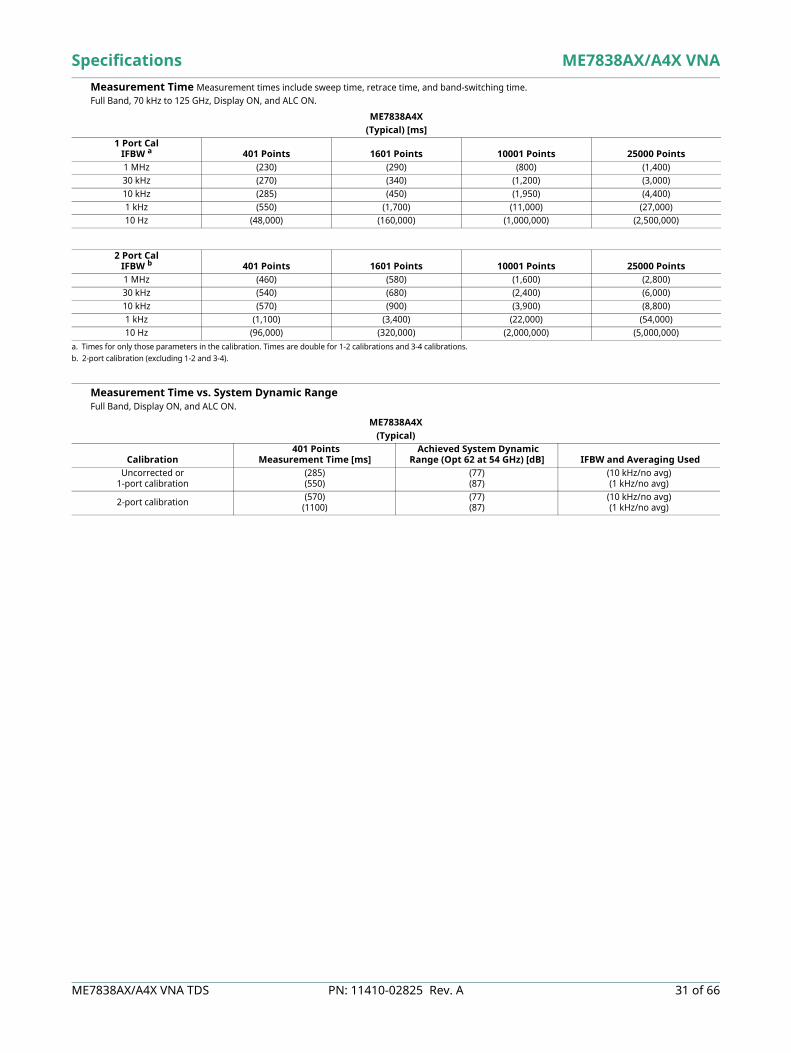
Measurement Time Measurement times include sweep time, retrace time, and band-switching time.Full Band, 70 kHz to 125 GHz, Display ON, and ALC ON.
ME7838AX(Typical)
Frequency RangeMagnitude
[dB/°C]Phase
[deg/°C]70 to 300 kHz (< 0.015) (< 0.1)> 0.3 to 2 MHz (< 0.015) (< 0.05)> 2 to 10 MHz (< 0.01) (< 0.05)
> 0.01 to < 2.5 GHz (< 0.01) (< 0.05)2.5 to 30 GHz (< 0.01) (< 0.09)
> 30 to 54 GHz (< 0.01) (< 0.07)> 54 to 80 GHz (< 0.015) (< 0.1)
> 80 to 110 GHz (< 0.015) (< 0.15)> 110 to 120 GHz (< 0.02) (< 0.2)> 120 to 125 GHz (< 0.04) (<0.25)
ME7838AX(Typical)
Frequency (GHz) Directivity (dB) Port Match (dB)70 kHz to 0.01 MHz (10 a)
a. Raw directivity is degraded below 300 kHz, 2.2 to 2.5 GHz and in narrow bands within 10 to 34 GHz.
(8)> 0.01 to 2.5 (9 a) (10)> 2.5 to 30 (5 a) (12)> 30 to 40 (5 a) (5)> 40 to 54 (10) (5)> 54 to 80 (10) (10)
> 80 to 110 (5) (7)> 110 to 120 b
b. 110 to 125 GHz frequency range is available as characteristic.
(5) (7)> 120 to 125 b (5) (7)
ME7838AXSpecifications
Resolution Accuracy Stability
1 Hz ± 5 x 10⁻⁷ Hz/Hz
(at time of calibration) < 5 x 10⁻⁹/°C over 0 °C to 50 °C temperature
< 1 x 10⁻⁹/day aging, instrument on
ME7838AX(Typical) [ms]
1 Port CalIFBW 401 Points 1601 Points 10001 Points 25000 Points1 MHz (230) (290) (800) (1,400)30 kHz (270) (340) (1,200) (3,000)10 kHz (285) (450) (1,950) (4,400)1 kHz (550) (1,700) (11,000) (27,000)10 Hz (48,000) (160,000) (1,000,000) (2,500,000)
2 Port CalIFBW a
a. Times for only those parameters in the calibration. Times are double for 1-2 calibrations and 3-4 calibrations.
401 Points 1601 Points 10001 Points 25000 Points1 MHz (460) (580) (1,600) (2,800)30 kHz (540) (680) (2,400) (6,000)10 kHz (570) (900) (3,900) (8,800)1 kHz (1,100) (3,400) (22,000) (54,000)10 Hz (96,000) (320,000) (2,000,000) (5,000,000)

ME7838AX/A4X VNA Specifications
14 of 66 PN: 11410-02825 Rev. A ME7838AX/A4X VNA TDS
Measurement Time vs. System Dynamic Range Full Band, Display ON, and ALC ON.
ME7838AX(Typical)
Calibration 401 Points
Measurement Time [ms] Achieved System Dynamic
Range (Opt 62 at 54 GHz) [dB] IFBW and Averaging Used Uncorrected or
1-port calibration(285)(550)
(77)(87)
(10 kHz/no avg)(1 kHz/no avg)
2-port calibration a
a. 2-port calibration (excluding 1-2 and 3-4).
(570)(1100)
(77)(87)
(10 kHz/no avg)(1 kHz/no avg)

Specifications ME7838AX/A4X VNA
ME7838AX/A4X VNA TDS PN: 11410-02825 Rev. A 15 of 66
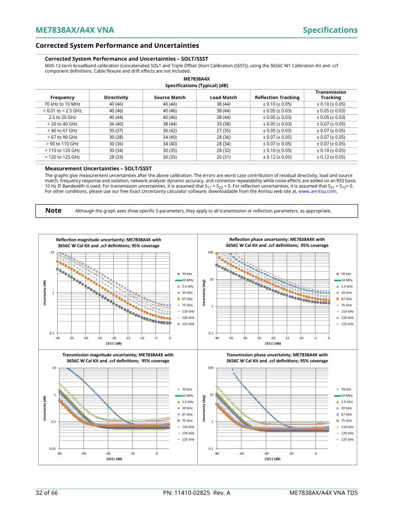
Corrected System Performance and Uncertainties
Corrected System Performance and Uncertainties – SOLT/SSST With 12-term broadband calibration (concatenated SOLT and Triple Offset Short Calibration (SSST)), using the 3656C W1 Calibration Kit and .ccf component definitions. Cable flexure and drift effects are not included.
The graphs give measurement uncertainties after the above calibration. The errors are worst case contribution of residual directivity, load and source match, frequency response and isolation, network analyzer dynamic accuracy, and connector repeatability while noise effects are added on an RSS basis. 10 Hz IF Bandwidth is used. For transmission uncertainties, it is assumed that S11 = S22 = 0. For reflection uncertainties, it is assumed that S21 = S12 = 0. For other conditions, please use our free Exact Uncertainty calculator software, downloadable from the Anritsu web site at www.anritsu.com.
ME7838AXSpecifications (Typical) [dB]
Frequency Directivity Source Match Load Match Reflection TrackingTransmission
Tracking70 kHz to 10 MHz 40 (46) 40 (46) 38 (44) ± 0.10 (± 0.05) ± 0.10 (± 0.05)
> 0.01 to < 2.5 GHz 40 (46) 40 (46) 38 (44) ± 0.05 (± 0.03) ± 0.05 (± 0.03)2.5 to 20 GHz 40 (44) 40 (46) 38 (44) ± 0.05 (± 0.03) ± 0.05 (± 0.03)
> 20 to 40 GHz 36 (40) 38 (44) 33 (38) ± 0.05 (± 0.03) ± 0.07 (± 0.05) > 40 to 67 GHz 30 (37) 36 (42) 27 (35) ± 0.05 (± 0.03) ± 0.07 (± 0.05)> 67 to 90 GHz 30 (38) 34 (40) 30 (36) ± 0.07 (± 0.05) ± 0.07 (± 0.05)
> 90 to 110 GHz 30 (36) 34 (40) 28 (34) ± 0.07 (± 0.05) ± 0.07 (± 0.05)> 110 to 120 GHz 30 (34) 30 (35) 28 (32) ± 0.10 (± 0.05) ± 0.10 (± 0.05)> 120 to 125 GHz 28 (33) 30 (35) 26 (31) ± 0.12 (± 0.05) ± 0.12 (± 0.05)
0.1
1
10
-40 -35 -30 -25 -20 -15 -10 -5 0
Unc
erta
inty
(dB)
|S11| (dB)
Re ec on magnitude uncertainty; ME7838AX with 3656C W Cal Kit and .ccf de ni ons; 95% coverage
70 kHz
10 MHz
2.5 GHz
20 GHz
67 GHz
75 GHz
110 GHz
120 GHz
125 GHz
0.1
1
10
100
-40 -35 -30 -25 -20 -15 -10 -5 0
Unc
erta
inty
(deg
)
|S11| (dB)
Re ec on phase uncertainty; ME7838AX with 3656C W Cal Kit and .ccf de ni ons; 95% coverage
70 kHz
10 MHz
2.5 GHz
20 GHz
67 GHz
75 GHz
110 GHz
120 GHz
125 GHz
0.1
1
10
100
-80 -60 -40 -20 0
Unc
erta
inty
(deg
)
|S21| (dB)
Transmission phase uncertainty; ME7838AX with 3656C W Cal Kit and .ccf de ni ons; 95% coverage
70 kHz
10 MHz
2.5 GHz
20 GHz
67 GHz
75 GHz
110 GHz
120 GHz
125 GHz
0.01
0.1
1
10
-80 -60 -40 -20 0
Unc
erta
inty
(dB)
|S21| (dB)
Transmission magnitude uncertainty; ME7838AX with 3656C W Cal Kit and .ccf de ni ons; 95% coverage
70 kHz
10 MHz
2.5 GHz
20 GHz
67 GHz
75 GHz
110 GHz
120 GHz
125 GHz
ME7838AX/A4X VNA Specifications
16 of 66 PN: 11410-02825 Rev. A ME7838AX/A4X VNA TDS
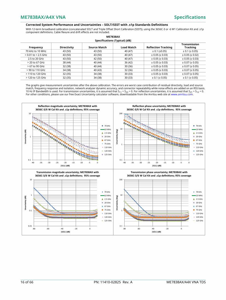
Corrected System Performance and Uncertainties – SOLT/SSST with .s1p Standards Definitions With 12-term broadband calibration (concatenated SOLT and Triple Offset Short Calibration (SSST)), using the 3656C-3 or -6 W1 Calibration Kit and .s1p component definitions. Cable flexure and drift effects are not included.
The graphs give measurement uncertainties after the above calibration. The errors are worst case contribution of residual directivity, load and source match, frequency response and isolation, network analyzer dynamic accuracy, and connector repeatability while noise effects are added on an RSS basis. 10 Hz IF Bandwidth is used. For transmission uncertainties, it is assumed that S11 = S22 = 0. For reflection uncertainties, it is assumed that S21 = S12 = 0. For other conditions, please use our free Exact Uncertainty calculator software, downloadable from the Anritsu web site at www.anritsu.com.
ME7838AXSpecifications (Typical) [dB]
Frequency Directivity Source Match Load Match Reflection TrackingTransmission
Tracking70 kHz to 10 MHz 43 (50) 43 (50) 40 (47) ± 0.1 (±0.05) ± 0.1 (± 0.05)
> 0.01 to < 2.5 GHz 43 (50) 43 (50) 40 (47) ± 0.05 (± 0.03) ± 0.05 (± 0.02)2.5 to 20 GHz 43 (50) 42 (50) 40 (47) ± 0.05 (± 0.03) ± 0.05 (± 0.03)
> 20 to 67 GHz 38 (44) 40 (44) 36 (42) ± 0.05 (± 0.03) ± 0.07 (± 0.05)> 67 to 90 GHz 32 (38) 40 (44) 30 (36) ± 0.05 (± 0.03) ± 0.07 (± 0.05)
> 90 to 110 GHz 34 (38) 40 (43) 32 (36) ± 0.05 (± 0.03) ± 0.07 (± 0.05)> 110 to 120 GHz 32 (35) 34 (38) 30 (33) ± 0.05 (± 0.03) ± 0.07 (± 0.05)> 120 to 125 GHz 32 (35) 34 (38) 30 (33) ± 0.1 (± 0.05) ± 0.1 (± 0.05)
0.1
1
10
-40 -35 -30 -25 -20 -15 -10 -5 0
Unc
erta
inty
(dB)
|S11| (dB)
Re ec on magnitude uncertainty; ME7838AX with 3656C-3/6 W Cal Kit and .s1p de ni ons; 95% coverage
70 kHz
10 MHz
2.5 GHz
20 GHz
67 GHz
75 GHz
110 GHz
120 GHz
125 GHz
0.1
1
10
100
-40 -35 -30 -25 -20 -15 -10 -5 0
Unc
erta
inty
(deg
)
|S11| (dB)
Re ec on phase uncertainty; ME7838AX with 3656C-3/6 W Cal Kit and .s1p de ni ons; 95% coverage
70 kHz
10 MHz
2.5 GHz
20 GHz
67 GHz
75 GHz
110 GHz
120 GHz
125 GHz
0.01
0.1
1
10
-80 -60 -40 -20 0
Unc
erta
inty
(dB)
|S21| (dB)
Transmission magnitude uncertainty; ME7838AX with 3656C-3/6 W Cal Kit and .s1p de ni ons; 95% coverage
70 kHz
10 MHz
2.5 GHz
20 GHz
67 GHz
75 GHz
110 GHz
120 GHz
125 GHz
0.1
1
10
100
-80 -60 -40 -20 0
Unc
erta
inty
(deg
)
|S21| (dB)
Transmission phase uncertainty; ME7838AX with 3656C-3/6 W Cal Kit and .s1p de ni ons; 95% coverage
70 kHz
10 MHz
2.5 GHz
20 GHz
67 GHz
75 GHz
110 GHz
120 GHz
125 GHz
Specifications ME7838AX/A4X VNA
ME7838AX/A4X VNA TDS PN: 11410-02825 Rev. A 17 of 66
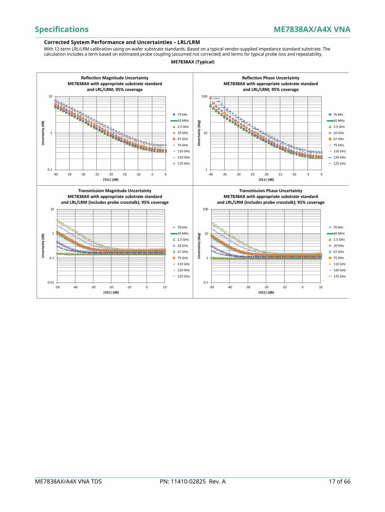
Corrected System Performance and Uncertainties – LRL/LRM With 12-term LRL/LRM calibration using on-wafer substrate standards. Based on a typical vendor-supplied impedance standard substrate. The calculation includes a term based on estimated probe coupling (assumed not corrected) and terms for typical probe loss and repeatability.
ME7838AX (Typical)
0.1
1
10
-40 -35 -30 -25 -20 -15 -10 -5 0
Unc
erta
inty
(dB)
|S11| (dB)
Re ec on Magnitude UncertaintyME7838AX with appropriate substrate standard
and LRL/LRM; 95% coverage
70 kHz
10 MHz
2.5 GHz
20 GHz
67 GHz
75 GHz
110 GHz
120 GHz
125 GHz
1
10
100
-40 -35 -30 -25 -20 -15 -10 -5 0
Unc
erta
inty
(deg
)
|S11| (dB)
Re ec on Phase UncertaintyME7838AX with appropriate substrate standard
and LRL/LRM; 95% coverage
70 kHz
10 MHz
2.5 GHz
20 GHz
67 GHz
75 GHz
110 GHz
120 GHz
125 GHz
0.01
0.1
1
10
-50 -40 -30 -20 -10 0 10
Unc
erta
inty
(dB)
|S21| (dB)
Transmission Magnitude UncertaintyME7838AX with appropriate substrate standard
and LRL/LRM (includes probe crosstalk); 95% coverage
70 kHz
10 MHz
2.5 GHz
20 GHz
67 GHz
75 GHz
110 GHz
120 GHz
125 GHz
0.1
1
10
100
-50 -40 -30 -20 -10 0 10
Unc
erta
inty
(deg
)
|S21| (dB)
Transmission Phase UncertaintyME7838AX with appropriate substrate standard
and LRL/LRM (includes probe crosstalk); 95% coverage
70 kHz
10 MHz
2.5 GHz
20 GHz
67 GHz
75 GHz
110 GHz
120 GHz
125 GHz

ME7838AX/A4X VNA Specifications
18 of 66 PN: 11410-02825 Rev. A ME7838AX/A4X VNA TDS
Broadband Measurement Examples The following figures are measurement examples of typical ME7838AX Broadband system performance.
ME7838AX
Typical dynamic range of ME7838AX system at the W1 1 mm coaxial test port from 70 kHz to 125 GHz.
An example of typical power measurement agreement: power sensor vs. ME7838AX a1 reference receiver.
10 GHz 125 GHz
Pow er Meter vs a1/1 Receiver
–10.5
–10.4
–10.3
–10.2
–10.1
–10
–9.9
–9.8
–9.7
–9.6
–9.5
0 10 20 29 39 48 58 67 76 86 95 105 114 125
Frequency (GHz)
dBm
| a1/1|
Power Meter

Specifications ME7838AX/A4X VNA
ME7838AX/A4X VNA TDS PN: 11410-02825 Rev. A 19 of 66
ME7838AX
Typical power sweep range at 77 GHz.By using detection and power control inside the 3743AX mmWave module,improved accuracy, linearity and range can be achieved.
Typical power sweep range at 94 GHz demonstrating greater than 50 dB of control.

ME7838AX/A4X VNA Specifications
20 of 66 PN: 11410-02825 Rev. A ME7838AX/A4X VNA TDS
Stability plots are obtained using simple normalization (except for those labeled vector-delta) in a controlled environment.
ME7838AX
Typical 24-Hour Transmission Magnitude Stability
Typical 24-Hour Transmission Phase Stability
-0.2
-0.1
0
0.1
0.2
0 20 40 60 80 100 120
dB
Frequency (GHz)
24-hour, 25 °C Transmission Magnitude Stability
S21 S12
-3
-2
-1
0
1
2
3
0 20 40 60 80 100 120
Degr
ees
Frequency (GHz)
24-Hour, 25 °C Transmission Phase Stability
S21 S12

Specifications ME7838AX/A4X VNA
ME7838AX/A4X VNA TDS PN: 11410-02825 Rev. A 21 of 66
ME7838AX
Typical 24-Hour Thru Line Match Vector-delta Stability
Typical 24-Hour Reflection Magnitude Stability
-80
-60
-40
-20
0
0 20 40 60 80 100 120
dB
Frequency (GHz)
24-hour, 25 °C Re ec on (of Thru) Vector- delta Stability
S11 S22
-0.1
-0.05
0
0.05
0.1
0 20 40 60 80 100 120
dB
Frequency (GHz)
24-hour, 25 °C Re ec on Magnitude Stability (Short Measurement)
S11 S22
ME7838AX/A4X VNA Specifications
22 of 66 PN: 11410-02825 Rev. A ME7838AX/A4X VNA TDS
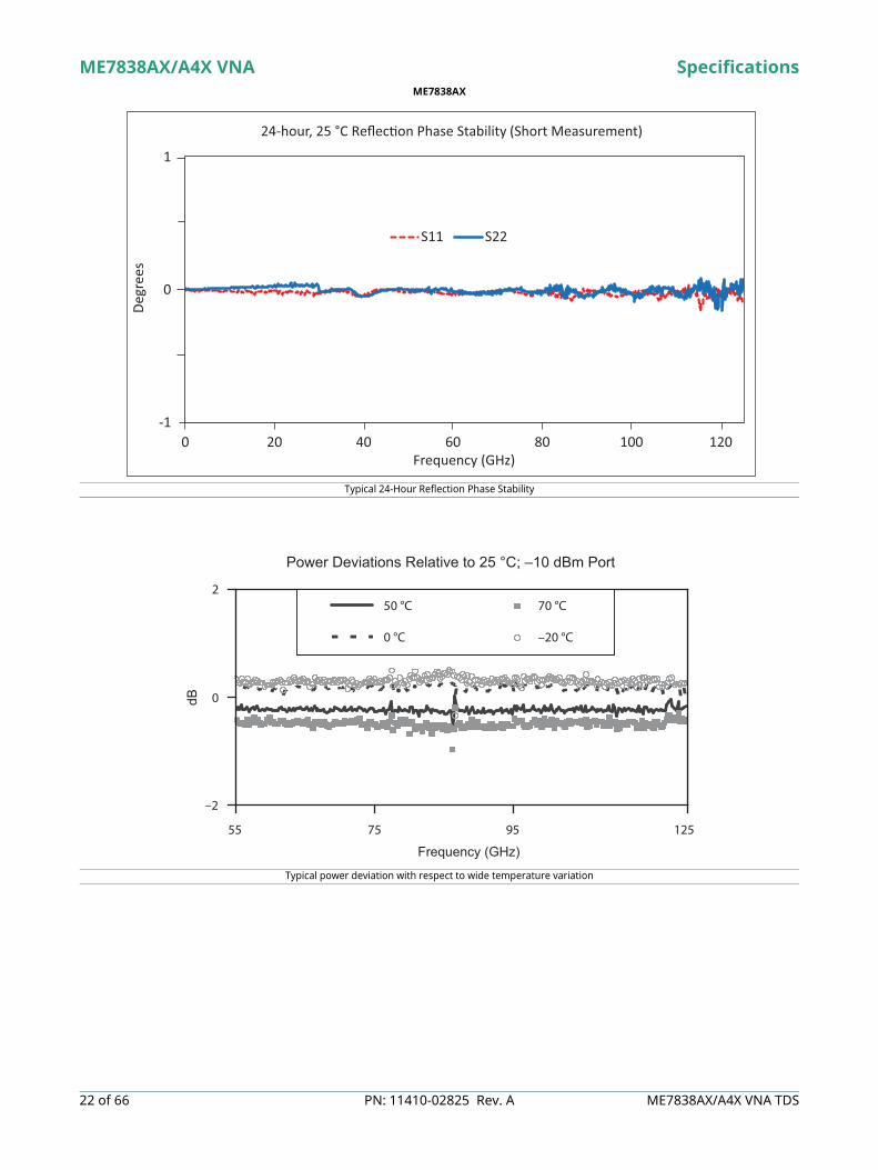
ME7838AX
Typical 24-Hour Reflection Phase Stability
Typical power deviation with respect to wide temperature variation
-1
0
1
0 20 40 60 80 100 120
Degr
ees
Frequency (GHz)
24-hour, 25 °C Re ec on Phase Stability (Short Measurement)
S11 S22
Power Deviations Relative to 25 °C; –10 dBm Port
–2
0
2
55 75 95 125
Frequency (GHz)
50 °C 70 °C
0 °C –20 °C
dB

Specifications ME7838AX/A4X VNA
ME7838AX/A4X VNA TDS PN: 11410-02825 Rev. A 23 of 66
ME7838A4X 4-Port VNA
ME7838AX/A4X VNA Specifications
24 of 66 PN: 11410-02825 Rev. A ME7838AX/A4X VNA TDS
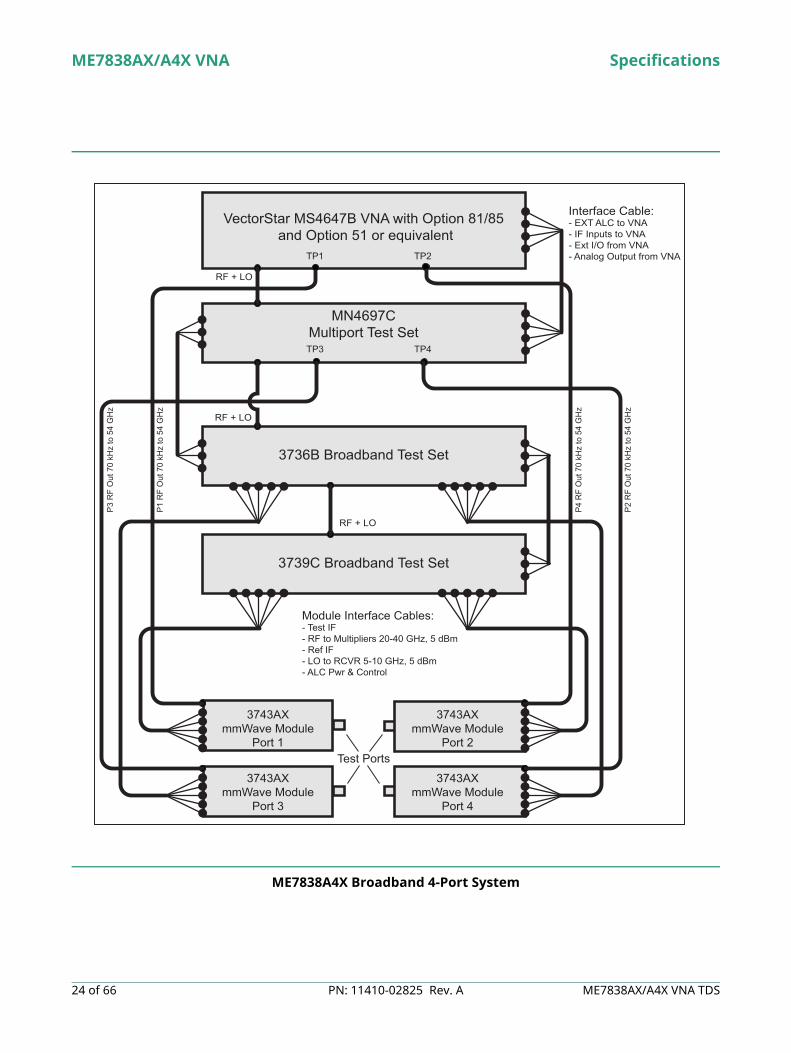
ME7838A4X Broadband 4-Port System
VectorStar MS4647B VNA with Option 81/85 and Option 51 or equivalent
3736B Broadband Test Set
Test Ports
Module Interface Cables:- Test IF- RF to Multipliers 20-40 GHz, 5 dBm- Ref IF- LO to RCVR 5-10 GHz, 5 dBm- ALC Pwr & Control
Interface Cable:- EXT ALC to VNA- IF Inputs to VNA- Ext I/O from VNA- Analog Output from VNA
RF + LO
RF + LO
RF + LO
P1 R
F O
ut 7
0 kH
z to
54
GH
z
P4 R
F O
ut 7
0 kH
z to
54
GH
z
P3 R
F O
ut 7
0 kH
z to
54
GH
z
P2 R
F O
ut 7
0 kH
z to
54
GH
z
3739C Broadband Test Set
MN4697CMultiport Test Set
3743AXmmWave Module
Port 3
TP2
TP3 TP4
TP1
3743AXmmWave Module
Port 4
3743AXmmWave Module
Port 2
3743AXmmWave Module
Port 1

Specifications ME7838AX/A4X VNA
ME7838AX/A4X VNA TDS PN: 11410-02825 Rev. A 25 of 66
ME7838A4X mmWave 4-Port System
VectorStar MS4640B VNA with Option 83/85 and Option 51 or equivalent
3736B Broadband Test Set
mmWave ModulePort 1
mmWave ModulePort 2
Module Interface Cables:- Test IF- RF to Multipliers- Ref IF- LO to RCVR
Interface Cable:- EXT ALC to VNA- IF Inputs to VNA- Ext I/O from VNA- Analog Output from VNA- GPIB
RF + LO
RF + LO
3739C Broadband Test Set
MN469xC4-Port Test Set
mmWave ModulePort 3
mmWave ModulePort 4
Test Ports
ME7838AX/A4X VNA Specifications
26 of 66 PN: 11410-02825 Rev. A ME7838AX/A4X VNA TDS
Dynamic Range Specifications
System Dynamic Range (Excludes localized spurious responses and crosstalk)System Dynamic Range System dynamic range is measured as the difference between maximum port power and the RMS noise
floor in a 10 Hz bandwidth and no averaging (ports terminated).Normalizing Measurement Normalizing measurement made with a through line connection, with its effects compensated for. The
cables between the VNA and the 3743AX modules are assumed to be the 806-206-R 1.85 mm cable (61 cm, 24 in long) or the 806-209-R 1.85 mm cable (91.5 cm, 36 in long).
Receiver Dynamic Range (Excludes localized spurious responses and crosstalk)Receiver Dynamic Range is calculated as the difference between the receiver compression level and the noise floor at Ports 1 or 2.
ME7838A4X a,b
a. Option 51 is the minimum required option for 4-port baseband VNAs.b. Table represents dynamic range with Ports 1 and/or 3 driving. With Port 2 driving, dynamic range may be up to 7 dB lower in the 2.5-54 GHz bands. With Port 4 driving, dynamic
range may be up to 3 dB higher in the 2.5-54 GHz bands.
Specifications (Typical) [dB]
Frequency Range Option 51 Option 61 or 62 Option 31
and Option 51Option 31
and Option 61 or 6270 to 300 kHz 82 (100) 82 (100) 84 (102) 84 (102)> 0.3 to 2 MHz 92 (100) 92 (100) 94 (102) 94 (102)> 2 to 10 MHz 100 (115) 100 (115) 102 (118) 102 (115)
> 0.01 to < 2.5 GHz 108 (120) 108 (120) 111 (124) 110 (120)2.5 to 10 GHz 107 (116) 104 (112) 110 (118) 104 (114)
> 10 to 24 GHz 98 (112) 92 (101) 102 (113) 95 (105)> 24 to 40 GHz 95 (105) 90 (101) 100 (108) 95 (105)> 40 to 54 GHz 94 (104) 87 (96) 99 (108) 93 (104)> 54 to 60 GHz 107 (116) 107 (116) 107 (116) 107 (116)> 60 to 65 GHz 107 (116) 107 (116) 107 (116) 107 (116)> 65 to 80 GHz 106 (116) 106 (116) 106 (116) 106 (116)> 80 to 90 GHz 104 (110) 104 (110) 104 (110) 104 (110)
> 90 to 100 GHz 104 (110) 104 (110) 104 (110) 104 (110)> 100 to 110 GHz 104 (110) 104 (110) 104 (110) 104 (110)> 110 to 115 GHz 103 (112) 103 (112) 103 (112) 103 (112)> 115 to 120 GHz 95 (106) 95 (106) 95 (106) 95 (106)> 120 to 125 GHz 95 (106) 95 (106) 95 (106) 95 (106)
ME7838A4X a
a. Option 51 is required for 4-port baseband VNAs.
Specifications (Typical) [dB]
Frequency Range Option 51 Option 61 or 62Option 31
and Option 51Option 31
and Option 61 or 6270 to 300 kHz 82 (96) 83 (96) 82 (95) 82 (95)> 0.3 to 2 MHz 98 (102) 100 (103) 98 (101) 99 (102)> 2 to 10 MHz 107 (117) 108 (118) 106 (117) 107 (115)
> 0.01 to < 2.5 GHz 115 (122) 117 (124) 115 (123) 117 (121)2.5 to 10 GHz 122 (125) 122 (123) 124 (124) 121 (122)
> 10 to 24 GHz 117 (127) 115 (119) 120 (125) 116 (120)> 24 to 40 GHz 115 (119) 112 (117) 119 (120) 115 (119)> 40 to 54 GHz 121 (125) 117 (120) 122 (126) 118 (124)> 54 to 60 GHz 119 (125) 119 (125) 119 (125) 119 (125)> 60 to 65 GHz 119 (124) 119 (124) 119 (124) 119 (124)> 65 to 70 GHz 122 (127) 122 (127) 122 (127) 122 (127)> 70 to 80 GHz 120.5 (127) 120.5 (127) 120.5 (127) 120.5 (127)> 80 to 90 GHz 120.5 (122) 120.5 (122) 120.5 (122) 120.5 (122)
> 90 to 100 GHz 116.5 (118) 116.5 (118) 116.5 (118) 116.5 (118)> 100 to 110 GHz 120.5 (123) 120.5 (123) 120.5 (123) 120.5 (123)> 110 to 115 GHz 120 (123) 120 (123) 120 (123) 120 (123)> 115 to 120 GHz 103 (108) 103 (108) 103 (108) 103 (108)> 120 to 125 GHz 103 (108) 103 (108) 103 (108) 103 (108)

Specifications ME7838AX/A4X VNA
ME7838AX/A4X VNA TDS PN: 11410-02825 Rev. A 27 of 66
Power Specifications Maximum Power and Power Range tables represent powers available at Ports 1 and 3. Max Power may be up to 4 dB lower on Port 2 in the 2.5 GHz to 54 GHz bands. Max Power may be up to 3 dB higher on Port 4 in the 22.5 GHz to 54 GHz bands.
Maximum Power Maximum port power is determined by the base VNA for frequencies below 54 GHz, and by the 3743AX mmWave module for frequencies greater than 54 GHz.
Power Range .
ME7838A4X a
a. Using the 806–206-R 1.85 mm (61 cm, 24 in long) test port cables between the VNA and the 3743AX mmWave modules.
Specifications (Typical) [dB]
Frequency Range Option 51 Option 61 or 62Option 31
and Option 51Option 31
and Option 61 or 6270 to 300 kHz 6 (10) 5 (10) 8 (13) 8 (13)> 0.3 to 2 MHz 6 (10) 5 (10) 8 (13) 8 (13)> 2 to 10 MHz 5 (10) 5 (10) 8 (13) 8 (13)
> 0.01 to < 2.5 GHz 5 (10) 5 (10) 8 (13) 7 (13)2.5 to 10 GHz -3 (3) -4 (3) -2 (6) -3 (6)
> 10 to 24 GHz -7 (-3) -9 (-4) -6 (0) -7 (-1)> 24 to 40 GHz -10 (-4) -12 (-6) -9 (-2) -10 (-4)> 40 to 54 GHz -17 (-11) -20 (-14) -13 (-8) -15 (-10)> 54 to 60 GHz -2 (1) -2 (1) -2 (1) -2 (1)> 60 to 65 GHz -2 (2) -2 (2) -2 (2) -2 (2)> 65 to 70 GHz -6 (-1) -6 (-1) -6 (-1) -6 (-1)> 70 to 80 GHz -4.5 (-1) -4.5 (-1) -4.5 (-1) -4.5 (-1)> 80 to 90 GHz -6.5 (-2) -6.5 (-2) -6.5 (-2) -6.5 (-2)
> 90 to 100 GHz -2.5 (2) -2.5 (2) -2.5 (2) -2.5 (2)> 100 to 110 GHz -6.5 (-3) -6.5 (-3) -6.5 (-3) -6.5 (-3)> 110 to 115 GHz -7 (-1) -7 (-1) -7 (-1) -7 (-1)> 115 to 120 GHz -3 (3) -3 (3) -3 (3) -3 (3)> 120 to 125 GHz -3 (3) -3 (3) -3 (3) -3 (3)
ME7838A4XSpecifications [dB]
Frequency Range Option 51 Option 61 or 62Option 31
and Option 51Option 31
and Option 61 or 6270 to 300 kHz 6 to –25 5 to –85 8 to –25 8 to –85> 0.3 to 2 MHz 6 to –25 5 to –85 8 to –25 8 to –85> 2 to 10 MHz 5 to –25 5 to –85 8 to –25 8 to –85
> 0.01 to < 2.5 GHz 5 to –25 5 to –85 8 to –25 7 to –852.5 to 10 GHz -3 to –25 -4 to –85 -2 to –25 -3 to –85
> 10 to 24 GHz -7 to -25 -9 to -85 -6 to -25 -7 to -85> 24 to 40 GHz -10 to –30 -12 to –90 -9 to –30 -10 to –90> 40 to 54 GHz -17 to –30 -20 to –90 -13 to –30 -15 to –90> 54 to 60 GHz -2 to –55 -2 to –55 -2 to –55 -2 to –55> 60 to 65 GHz -2 to –55 -2 to –55 -2 to –55 -2 to –55> 65 to 70 GHz -6 to -55 -6 to -55 -6 to -55 -6 to -55> 70 to 80 GHz -4.5 to –55 -4.5 to –55 -4.5 to –55 -4.5 to –55> 80 to 90 GHz -6.5 to –55 -6.5 to –55 -6.5 to –55 -6.5 to –55
> 90 to 100 GHz -2.5 to –55 -2.5 to –55 -2.5 to –55 -2.5 to –55> 100 to 110 GHz -6.5 to –55 -6.5 to –55 -6.5 to –55 -6.5 to –55> 110 to 115 GHz -7 to –55 -7 to –55 -7 to –55 -7 to –55> 115 to 120 GHz -3 to –40 -3 to –40 -3 to –40 -3 to –40> 120 to 125 GHz -3 to –40 -3 to –40 -3 to –40 -3 to –40
ME7838AX/A4X VNA Specifications
28 of 66 PN: 11410-02825 Rev. A ME7838AX/A4X VNA TDS
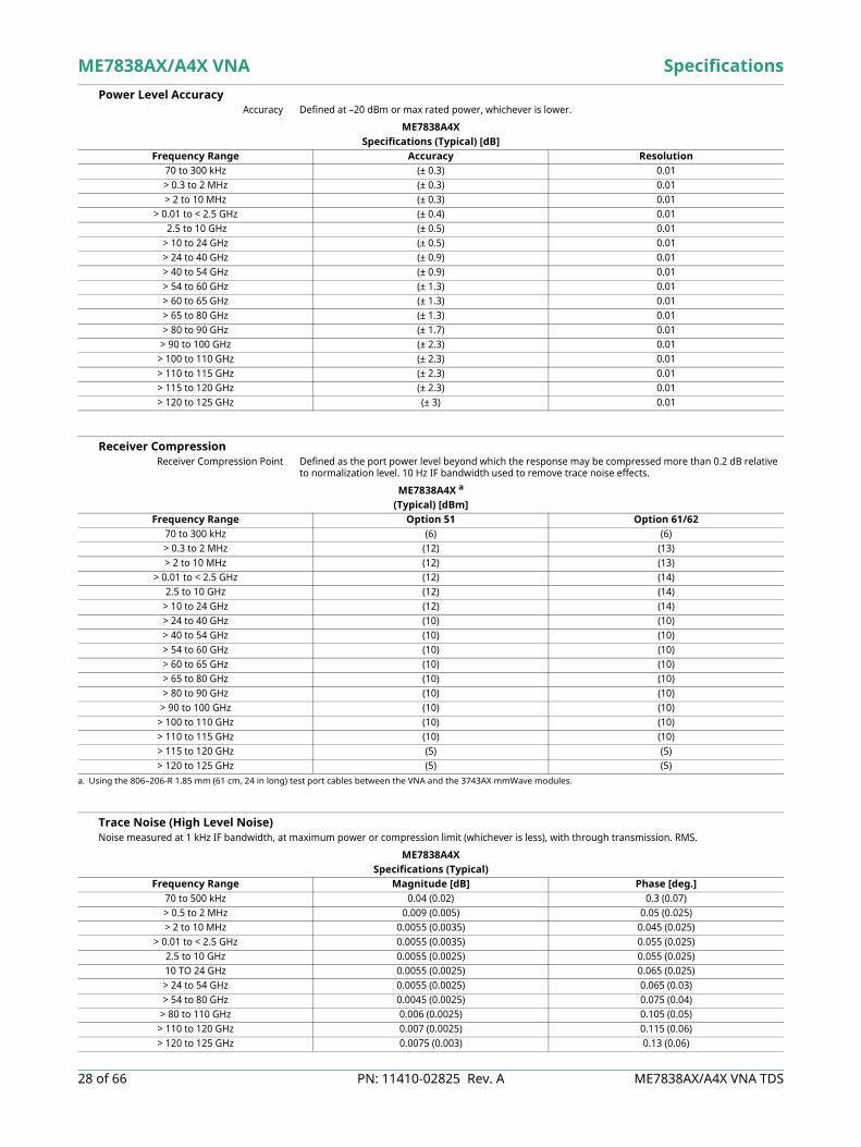
Power Level Accuracy Accuracy Defined at –20 dBm or max rated power, whichever is lower.
Receiver Compression Receiver Compression Point Defined as the port power level beyond which the response may be compressed more than 0.2 dB relative
to normalization level. 10 Hz IF bandwidth used to remove trace noise effects.
Trace Noise (High Level Noise) Noise measured at 1 kHz IF bandwidth, at maximum power or compression limit (whichever is less), with through transmission. RMS.
ME7838A4XSpecifications (Typical) [dB]
Frequency Range Accuracy Resolution70 to 300 kHz (± 0.3) 0.01> 0.3 to 2 MHz (± 0.3) 0.01> 2 to 10 MHz (± 0.3) 0.01
> 0.01 to < 2.5 GHz (± 0.4) 0.01 2.5 to 10 GHz (± 0.5) 0.01> 10 to 24 GHz (± 0.5) 0.01> 24 to 40 GHz (± 0.9) 0.01> 40 to 54 GHz (± 0.9) 0.01> 54 to 60 GHz (± 1.3) 0.01> 60 to 65 GHz (± 1.3) 0.01> 65 to 80 GHz (± 1.3) 0.01> 80 to 90 GHz (± 1.7) 0.01
> 90 to 100 GHz (± 2.3) 0.01> 100 to 110 GHz (± 2.3) 0.01> 110 to 115 GHz (± 2.3) 0.01> 115 to 120 GHz (± 2.3) 0.01> 120 to 125 GHz (± 3) 0.01
ME7838A4X a
a. Using the 806–206-R 1.85 mm (61 cm, 24 in long) test port cables between the VNA and the 3743AX mmWave modules.
(Typical) [dBm]Frequency Range Option 51 Option 61/62
70 to 300 kHz (6) (6)> 0.3 to 2 MHz (12) (13)> 2 to 10 MHz (12) (13)
> 0.01 to < 2.5 GHz (12) (14)2.5 to 10 GHz (12) (14)
> 10 to 24 GHz (12) (14)> 24 to 40 GHz (10) (10)> 40 to 54 GHz (10) (10)> 54 to 60 GHz (10) (10)> 60 to 65 GHz (10) (10)> 65 to 80 GHz (10) (10)> 80 to 90 GHz (10) (10)
> 90 to 100 GHz (10) (10)> 100 to 110 GHz (10) (10)> 110 to 115 GHz (10) (10)> 115 to 120 GHz (5) (5)> 120 to 125 GHz (5) (5)
ME7838A4XSpecifications (Typical)
Frequency Range Magnitude [dB] Phase [deg.]70 to 500 kHz 0.04 (0.02) 0.3 (0.07)> 0.5 to 2 MHz 0.009 (0.005) 0.05 (0.025)> 2 to 10 MHz 0.0055 (0.0035) 0.045 (0.025)
> 0.01 to < 2.5 GHz 0.0055 (0.0035) 0.055 (0.025)2.5 to 10 GHz 0.0055 (0.0025) 0.055 (0.025)10 TO 24 GHz 0.0055 (0.0025) 0.065 (0.025)> 24 to 54 GHz 0.0055 (0.0025) 0.065 (0.03)> 54 to 80 GHz 0.0045 (0.0025) 0.075 (0.04)
> 80 to 110 GHz 0.006 (0.0025) 0.105 (0.05)> 110 to 120 GHz 0.007 (0.0025) 0.115 (0.06)> 120 to 125 GHz 0.0075 (0.003) 0.13 (0.06)

Specifications ME7838AX/A4X VNA
ME7838AX/A4X VNA TDS PN: 11410-02825 Rev. A 29 of 66
Frequency Resolution, Accuracy, and Stability
Noise Floor (Excludes localized spurious responses and crosstalk)Noise floor is calculated as the difference between maximum rated port power and system dynamic range.Normalizing measurement made with a through line connection, with its effects compensated for. The cables between the VNA and the 3743AX modules are assumed to be the 806-206-R 1.85 mm cable (61 cm, 24 in long) or the 806-209-R 1.85 mm cable (91.5 cm, 36 in long).
Source Phase Noise and Harmonics Measured at default power.
ME7838A4XSpecifications
Resolution Accuracy Stability
1 Hz ± 5 x 10⁻⁷ Hz/Hz
(at time of calibration) < 5 x 10⁻⁹/°C over 0 °C to 50 °C temperature
< 1 x 10⁻⁹/day aging, instrument on
ME7838A4XSpecifications (Typical) [dB]
Frequency Range Option 51 Option 61 or 62Option 31
and Option 51Option 31
and Option 61 or 6270 to 300 kHz -76 (-90) -77 (-90) -76 (-89) -76 (-89)> 0.3 to 2 MHz -86 (-90) -87 (-90) -86 (-89) -86 (-89)> 2 to 10 MHz -95 (-105) -95 (-105) -94 (-105) -94 (-102)
> 0.01 to < 2.5 GHz -103 (-110) -103 (-110) -103 (-111) -103 (-107)2.5 to 10 GHz -110 (-113) -108 (-109) -112 (-112) -107 (-108)10 to 24 GHz -105 (-115) -101 (-105) -108 (-113) -102 (-106)
> 24 to 40 GHz -105 (-109) -102 (-107) -109 (-110) -105 (-109)> 40 to 54 GHz -111 (-115) -107 (-110) -112 (-116) -108 (-114)> 54 to 60 GHz -109 (-115) -109 (-115) -109 (-115) -109 (-115)> 60 to 65 GHz -109 (-114) -109 (-114) -109 (-114) -109 (-114)> 65 to 70 GHz -112(-117) -112(-117) -112(-117) -112(-117)> 70 to 80 GHz -110.5 (-117) -110.5 (-117) -110.5 (-117) -110.5 (-117)> 80 to 90 GHz -110.5 (-112) -110.5 (-112) -110.5 (-112) -110.5 (-112)
> 90 to 100 GHz -106.5 (-108) -106.5 (-108) -106.5 (-108) -106.5 (-108)> 100 to 110 GHz -110.5 (-113) -110.5 (-113) -110.5 (-113) -110.5 (-113)> 110 to 115 GHz -110 (-113) -110 (-113) -110 (-113) -110 (-113)> 115 to 120 GHz -98 (-103) -98 (-103) -98 (-103) -98 (-103)> 120 to 125 GHz -98 (-103) -98 (-103) -98 (-103) -98 (-103)
ME7838A4X(Typical)
Frequency Range1 KHz Offset
[dB/Hz]10 kHz Offset
[dB/Hz]100 kHz Offset a
[dB/Hz]
a. Only applies for source frequencies > 300 kHz.
2nd Harmonic[dBc]
3rd Harmonic[dBc]
70 to 10 MHz (-86) (-83) (-88) (-25) (-30)> 0.01 to < 2.5 GHz (-90) (-92) (-96) (-35) (-35)
> 2.5 to 5 GHz (-93) (-94) (-95) (-35) (-45)> 5 to 10 GHz (-86) (-90) (-90) (-35) (-45)
> 10 to 20 GHz (-81) (-84) (-84) (-40) (-45)> 20 to 26.5GHz (-78) (-81) (-81) (-30) (-45)> 26.5 to 40 GHz (-72) (-76) (-78) (-45) (-45)> 40 to 54 GHz (-69) (-73) (-74) (-45) -> 54 to 80 GHz (-66) (-70) (-71) (-40) -
> 80 to 110 GHz (-62) (-66) (-68) - -> 110 to 120 GHz (-61) (-65) (-67) - -> 120 to 125 GHz (-60) (-64) (-66) - -

ME7838AX/A4X VNA Specifications
30 of 66 PN: 11410-02825 Rev. A ME7838AX/A4X VNA TDS
Magnitude and Phase Stability Ratioed measurement at maximum leveled power and with nominally a full coaxial reflect or a stable coaxial thru over the normal specified temperature range.
Uncorrected (Raw) Port Characteristics
ME7838A4X(Typical)
Frequency RangeMagnitude
[dB/°C]Phase
[deg/°C]70 to 300 kHz (< 0.015) (< 0.15)> 0.3 to 2 MHz (< 0.015) (< 0.1)> 2 to 10 MHz (< 0.02) (< 0.1)
> 0.01 to < 2.5 GHz (< 0.02) (< 0.08)2.5 to 24 GHz (< 0.02) (< 0.09)
> 30 to 54 GHz (< 0.02) (< 0.1)> 54 to 80 GHz (< 0.015) (< 0.1)
> 80 to 110 GHz (< 0.015) (< 0.15)> 110 to 120 GHz (< 0.02) (< 0.2)> 120 to 125 GHz (< 0.04) (< 0.25)
ME7838A4X(Typical)
Frequency (GHz) Directivity (dB) Port Match (dB)70 kHz to 0.01 MHz (10 a)
a. Raw directivity is degraded below 300 kHz, 2.2 to 2.5 GHz and in narrow bands within 10 to 34 GHz.
(8)> 0.01 to 2.5 (9 a) (10)> 2.5 to 30 (5 a) (12)> 30 to 40 (5 a) (5)> 40 to 54 (10) (5)> 54 to 80 (10) (10)
> 80 to 110 (5) (7)> 110 to 120 b
b. 110 to 125 GHz frequency range is available as characteristic.
(5) (7)> 120 to 125 b (5) (7)
Specifications ME7838AX/A4X VNA
ME7838AX/A4X VNA TDS PN: 11410-02825 Rev. A 31 of 66
Measurement Time Measurement times include sweep time, retrace time, and band-switching time.Full Band, 70 kHz to 125 GHz, Display ON, and ALC ON.
Measurement Time vs. System Dynamic Range Full Band, Display ON, and ALC ON.
ME7838A4X(Typical) [ms]
1 Port CalIFBW a
a. Times for only those parameters in the calibration. Times are double for 1-2 calibrations and 3-4 calibrations.
401 Points 1601 Points 10001 Points 25000 Points1 MHz (230) (290) (800) (1,400)30 kHz (270) (340) (1,200) (3,000)10 kHz (285) (450) (1,950) (4,400)1 kHz (550) (1,700) (11,000) (27,000)10 Hz (48,000) (160,000) (1,000,000) (2,500,000)
2 Port CalIFBW b
b. 2-port calibration (excluding 1-2 and 3-4).
401 Points 1601 Points 10001 Points 25000 Points1 MHz (460) (580) (1,600) (2,800)30 kHz (540) (680) (2,400) (6,000)10 kHz (570) (900) (3,900) (8,800)1 kHz (1,100) (3,400) (22,000) (54,000)10 Hz (96,000) (320,000) (2,000,000) (5,000,000)
ME7838A4X(Typical)
Calibration 401 Points
Measurement Time [ms] Achieved System Dynamic
Range (Opt 62 at 54 GHz) [dB] IFBW and Averaging Used Uncorrected or
1-port calibration(285)(550)
(77)(87)
(10 kHz/no avg)(1 kHz/no avg)
2-port calibration (570)(1100)
(77)(87)
(10 kHz/no avg)(1 kHz/no avg)
ME7838AX/A4X VNA Specifications
32 of 66 PN: 11410-02825 Rev. A ME7838AX/A4X VNA TDS
Corrected System Performance and Uncertainties
Corrected System Performance and Uncertainties – SOLT/SSST With 12-term broadband calibration (concatenated SOLT and Triple Offset Short Calibration (SSST)), using the 3656C W1 Calibration Kit and .ccf component definitions. Cable flexure and drift effects are not included.
Measurement Uncertainties – SOLT/SSST The graphs give measurement uncertainties after the above calibration. The errors are worst case contribution of residual directivity, load and source match, frequency response and isolation, network analyzer dynamic accuracy, and connector repeatability while noise effects are added on an RSS basis. 10 Hz IF Bandwidth is used. For transmission uncertainties, it is assumed that S11 = S22 = 0. For reflection uncertainties, it is assumed that S21 = S12= 0. For other conditions, please use our free Exact Uncertainty calculator software, downloadable from the Anritsu web site at, www.anritsu.com.
ME7838A4XSpecifications (Typical) [dB]
Frequency Directivity Source Match Load Match Reflection TrackingTransmission
Tracking70 kHz to 10 MHz 40 (46) 40 (46) 38 (44) ± 0.10 (± 0.05) ± 0.10 (± 0.05)
> 0.01 to < 2.5 GHz 40 (46) 40 (46) 38 (44) ± 0.05 (± 0.03) ± 0.05 (± 0.03)2.5 to 20 GHz 40 (44) 40 (46) 38 (44) ± 0.05 (± 0.03) ± 0.05 (± 0.03)
> 20 to 40 GHz 36 (40) 38 (44) 33 (38) ± 0.05 (± 0.03) ± 0.07 (± 0.05)> 40 to 67 GHz 30 (37) 36 (42) 27 (35) ± 0.05 (± 0.03) ± 0.07 (± 0.05)> 67 to 90 GHz 30 (38) 34 (40) 28 (36) ± 0.07 (± 0.05) ± 0.07 (± 0.05)
> 90 to 110 GHz 30 (36) 34 (40) 28 (34) ± 0.07 (± 0.05) ± 0.07 (± 0.05)> 110 to 120 GHz 30 (34) 30 (35) 28 (32) ± 0.10 (± 0.05) ± 0.10 (± 0.05)> 120 to 125 GHz 28 (33) 30 (35) 26 (31) ± 0.12 (± 0.05) ± 0.12 (± 0.05)
Note Although the graph axes show specific S-parameters, they apply to all transmission or reflection parameters, as appropriate.
0.1
1
10
-40 -35 -30 -25 -20 -15 -10 -5 0
Unc
erta
inty
(dB)
|S11| (dB)
Re ec on magnitude uncertainty; ME7838A4X with 3656C W Cal Kit and .ccf de ni ons; 95% coverage
70 kHz
10 MHz
2.5 GHz
20 GHz
67 GHz
75 GHz
110 GHz
120 GHz
125 GHz
0.1
1
10
100
-40 -35 -30 -25 -20 -15 -10 -5 0
Unc
erta
inty
(deg
)
|S11| (dB)
Re ec on phase uncertainty; ME7838A4X with 3656C W Cal Kit and .ccf de ni ons; 95% coverage
70 kHz
10 MHz
2.5 GHz
20 GHz
67 GHz
75 GHz
110 GHz
120 GHz
125 GHz
0.01
0.1
1
10
-80 -60 -40 -20 0
Unc
erta
inty
(dB)
|S21| (dB)
Transmission magnitude uncertainty; ME7838A4X with 3656C W Cal Kit and .ccf de ni ons; 95% coverage
70 kHz
10 MHz
2.5 GHz
20 GHz
67 GHz
75 GHz
110 GHz
120 GHz
125 GHz
0.1
1
10
100
-80 -60 -40 -20 0
Unc
erta
inty
(deg
)
|S21| (dB)
Transmission phase uncertainty; ME7838A4X with 3656C W Cal Kit and .ccf de ni ons; 95% coverage
70 kHz
10 MHz
2.5 GHz
20 GHz
67 GHz
75 GHz
110 GHz
120 GHz
125 GHz
Specifications ME7838AX/A4X VNA
ME7838AX/A4X VNA TDS PN: 11410-02825 Rev. A 33 of 66
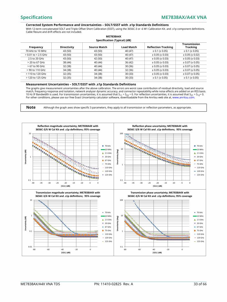
Corrected System Performance and Uncertainties – SOLT/SSST with .s1p Standards Definitions With 12-term concatenated SOLT and Triple Offset Short Calibration (SSST), using the 3656C-3 or -6 W1 Calibration Kit. and .s1p component definitions. Cable flexure and drift effects are not included.
Measurement Uncertainties – SOLT/SSST with .s1p Standards Definitions The graphs give measurement uncertainties after the above calibration. The errors are worst case contribution of residual directivity, load and source match, frequency response and isolation, network analyzer dynamic accuracy, and connector repeatability while noise effects are added on an RSS basis. 10 Hz IF Bandwidth is used. For transmission uncertainties, it is assumed that S11 = S22 = 0. For reflection uncertainties, it is assumed that S21 = S12= 0. For other conditions, please use our free Exact Uncertainty calculator software, downloadable from the Anritsu web site at, www.anritsu.com.
ME7838A4XSpecification (Typical) [dB]
Frequency Directivity Source Match Load Match Reflection Tracking Transmission
Tracking70 kHz to 10 MHz 43 (50) 43 (50) 40 (47) ± 0.1 (± 0.05) ± 0.1 (± 0.05)
> 0.01 to < 2.5 GHz 43 (50) 43 (50) 40 (47) ± 0.05 (± 0.03) ± 0.05 (± 0.02)2.5 to 20 GHz 43 (50) 42 (50) 40 (47) ± 0.05 (± 0.03) ± 0.05 (± 0.03)
> 20 to 67 GHz 38 (44) 40 (44) 36 (42) ± 0.05 (± 0.03) ± 0.07 (± 0.05)> 67 to 90 GHz 32 (38) 40 (44) 30 (36) ± 0.05 (± 0.03) ± 0.07 (± 0.05)
> 90 to 110 GHz 34 (38) 40 (44) 32 (36) ± 0.05 (± 0.03) ± 0.07 (± 0.05)> 110 to 120 GHz 32 (35) 34 (38) 30 (33) ± 0.05 (± 0.03) ± 0.07 (± 0.05)> 120 to 125 GHz 32 (35) 34 (38) 30 (33) ± 0.1 (± 0.05) ± 0.1 (± 0.05)
Note Although the graph axes show specific S-parameters, they apply to all transmission or reflection parameters, as appropriate.
0.1
1
10
-40 -35 -30 -25 -20 -15 -10 -5 0
Unc
erta
inty
(dB)
|S11| (dB)
Re ec on magnitude uncertainty; ME7838A4X with 3656C-3/6 W Cal Kit and .s1p de ni ons; 95% coverage
70 kHz
10 MHz
2.5 GHz
20 GHz
67 GHz
75 GHz
110 GHz
120 GHz
125 GHz
0.1
1
10
100
-40 -35 -30 -25 -20 -15 -10 -5 0
Unc
erta
inty
(deg
)
|S11| (dB)
Re ec on phase uncertainty; ME7838A4X with 3656C-3/6 W Cal Kit and .s1p de ni ons; 95% coverage
70 kHz
10 MHz
2.5 GHz
20 GHz
67 GHz
75 GHz
110 GHz
120 GHz
125 GHz
0.01
0.1
1
10
-80 -60 -40 -20 0
Unc
erta
inty
(dB)
|S21| (dB)
Transmission magnitude uncertainty; ME7838A4X with 3656C-3/6 W Cal Kit and .s1p de ni ons; 95% coverage
70 kHz
10 MHz
2.5 GHz
20 GHz
67 GHz
75 GHz
110 GHz
120 GHz
125 GHz
0.1
1
10
100
-80 -60 -40 -20 0
Unc
erta
inty
(deg
)
|S21| (dB)
Transmission phase uncertainty; ME7838A4X with 3656C-3/6 W Cal Kit and .s1p de ni ons; 95% coverage
70 kHz
10 MHz
2.5 GHz
20 GHz
67 GHz
75 GHz
110 GHz
120 GHz
125 GHz

ME7838AX/A4X VNA Specifications
34 of 66 PN: 11410-02825 Rev. A ME7838AX/A4X VNA TDS
Corrected System Performance and Uncertainties – LRL/LRM With 12 term LRL/LRM calibration using single-ended probes and on-wafer substrate standards. Based on a typical vendor supplied impedance standard substrate. The calculation includes a term based on estimated probe coupling (assumed not corrected) and terms for typical probe loss and repeatability.
ME7838A4X(Typical)
0.1
1
10
-40 -35 -30 -25 -20 -15 -10 -5 0
Unc
erta
inty
(dB)
|S11| (dB)
Re ec on Magnitude UncertaintyME7838A4X with appropriate substrate standard
and LRL/LRM; 95% coverage
70 kHz
10 MHz
2.5 GHz
20 GHz
67 GHz
75 GHz
110 GHz
120 GHz
125 GHz
1
10
100
-40 -35 -30 -25 -20 -15 -10 -5 0
Unc
erta
inty
(deg
)
|S11| (dB)
Re ec on Phase UncertaintyME7838A4X with appropriate substrate standard
and LRL/LRM; 95% coverage
70 kHz
10 MHz
2.5 GHz
20 GHz
67 GHz
75 GHz
110 GHz
120 GHz
125 GHz
0.01
0.1
1
10
-50 -40 -30 -20 -10 0 10
Unc
erta
inty
(dB)
|S21| (dB)
Transmission Magnitude UncertaintyME7838A4X with appropriate substrate standard and
LRL/LRM (includes probe crosstalk); 95% coverage
70 kHz
10 MHz
2.5 GHz
20 GHz
67 GHz
75 GHz
110 GHz
120 GHz
125 GHz
0.1
1
10
100
-50 -40 -30 -20 -10 0 10
Unc
erta
inty
(deg
)
|S21| (dB)
Transmission Phase UncertaintyME7838A4X with appropriate substrate standard and
LRL/LRM (includes probe crosstalk); 95% coverage
70 kHz
10 MHz
2.5 GHz
20 GHz
67 GHz
75 GHz
110 GHz
120 GHz
125 GHz
Specifications ME7838AX/A4X VNA
ME7838AX/A4X VNA TDS PN: 11410-02825 Rev. A 35 of 66
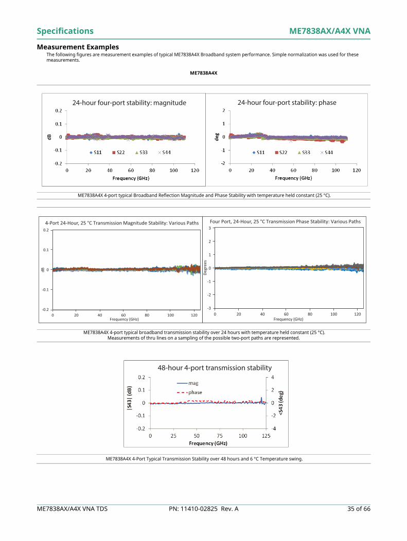
Measurement Examples The following figures are measurement examples of typical ME7838A4X Broadband system performance. Simple normalization was used for these measurements.
ME7838A4X
ME7838A4X 4-port typical Broadband Reflection Magnitude and Phase Stability with temperature held constant (25 °C).
ME7838A4X 4-port typical broadband transmission stability over 24 hours with temperature held constant (25 °C).Measurements of thru lines on a sampling of the possible two-port paths are represented.
ME7838A4X 4-Port Typical Transmission Stability over 48 hours and 6 °C Temperature swing.
24-hour four-port stability: phase24-hour four-port stability: magnitude
-0.2
-0.1
0
0.1
0.2
0 20 40 60 80 100 120
dB
Frequency (GHz)
4-Port 24-Hour, 25 °C Transmission Magnitude Stability: Various Paths
-3
-2
-1
0
1
2
3
0 20 40 60 80 100 120
Deg
rees
Frequency (GHz)
Four Port, 24-Hour, 25 °C Transmission Phase Stability: Various Paths
48-hour 4-port transmission stability

ME7838AX/A4X VNA Specifications
36 of 66 PN: 11410-02825 Rev. A ME7838AX/A4X VNA TDS
ME7838A4X 4-Port Broadband Typical Maximum Port PowerUnits with Option 31 will typically have higher maximum power below 54 GHz.
4-port broadband maximum port power (typ)
Specifications ME7838AX/A4X VNA
ME7838AX/A4X VNA TDS PN: 11410-02825 Rev. A 37 of 66
Accessories
ME7838AX/A4X VNA Specifications
38 of 66 PN: 11410-02825 Rev. A ME7838AX/A4X VNA TDS
SC8215 and SC7287 Kelvin Bias Tees Provides Sense and Force SMC connections close to the mmWave module to minimize the IR drops associated with the impedances between the bias tee and the DUT.
Part Number Description Voltage Current
SC8215
The SC8215 is a V-connectorized bias tee usable with the mmWave modules in the ME7838AX/A4X VNA for system frequencies of 70 kHz to 125 GHz. Stand-alone, it is usable to 70 GHz.
Max Voltage: 16 VDC Max Current: 100 mA
SC7287
The SC7287 is a V-connectorized bias tee usable with the mmWave modules in the ME7838AX/A4X VNA for system frequencies of 100 MHz to 125 GHz. Stand-alone, it is usable to 70 GHz.
Max Voltage: 50 VDC Max Current: 500 mA
Tri-Axial Output SMUsFor applications requiring Source Measure Units (SMU) with tri-axial outputs, a tri-axial (male) to SMC (male) cable is available, with the inner-shield isolated from ground at the bias tee SMC end, to float at the SMU guard potential.Check the accessories list for ordering information on page 63.
Specifications ME7838AX/A4X VNA
ME7838AX/A4X VNA TDS PN: 11410-02825 Rev. A 39 of 66
Waveguide Band Configuration Waveguide Band Specifications and Performance
ME7838AX/A4X VNA mmWave VNA, Waveguide Bands Three configurations are available for waveguide band operation for E and W bands when using the ME7838AX/A4X VNA system.
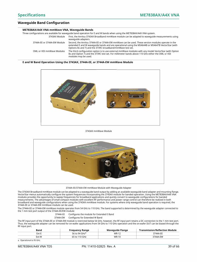
3743AX Module First, the Anritsu 3743AX Broadband mmWave module can be adapted to waveguide measurements using waveguide adapters.
3744A-EE or 3744A-EW Module Second, the Anritsu 3744A-EE or 3744A-EW mmWave can be used. These version modules operate in the extended E and W waveguide bands and are operational using the MS4644B or MS4647B VectorStar (with Options 8x and 7) and the 3739C broadband/mmWave test set.
OML or VDI mmWave Modules The third configuration option is to use external mmWave modules with any model VectorStar (with Option 8x and Option 7) and the 3739C test set. For millimeter bands above 110 GHz either the OML or VDI modules may be used.
E and W Band Operation Using the 3743AX, 3744A-EE, or 3744A-EW mmWave Module
The 3743AX Broadband mmWave module can be adapted to a waveguide band output by adding an available waveguide band adapter and mounting flange. VectorStar menus automatically configure the system frequencies incorporating the 3743AX module for banded operation. Using the ME7838AX/A4X VNA modules provides the opportunity to sweep frequencies for broadband applications and quickly convert to waveguide configurations for banded measurements. The advantages of small compact modules with excellent RF performance and power range control can therefore be realized in both broadband and waveguide configurations when using the 3743AX mmWave module. For systems where only waveguide band operation is required, the 3744A-EE or 3744A-EW mmWave module can be used.The 3744A-EE or 3744A-EW mmWave module operates from 54 GHz to 110 GHz. The band supported is determined by the waveguide adapter connected to the 1 mm test port output of the 3744A-EE/EW module:
3744A-EE Configures the module for Extended E Band3744A-EW Configures for Extended W Band
The RF input port of the 3744A-EE or 3744A-EW module is restricted below 54 GHz, however, the RF input port retains a DC connection to the 1 mm test port. Thus, the waveguide adapter can be removed for on-wafer applications from 54 GHz to 110 GHz operation and the on-wafer DUT can be biased through the RF input port.
3743AX mmWave Module
3744A-EE/3744A-EW mmWave Module with Waveguide Adapter
Band Frequency Range Waveguide Flange Transmission/Reflection ModuleExt-E 56 to 94 GHza
a. Operational to 95 GHz.
WR-12 3744A-EEExt-W 65 to 110 GHz WR-10 3744A-EW

ME7838AX/A4X VNA Specifications
40 of 66 PN: 11410-02825 Rev. A ME7838AX/A4X VNA TDS
Waveguide Band Specifications
Port Power, Noise Floor, Dynamic Range – 3744A-EE/3744A-EW mmWave Modules System dynamic range is defined as the ratio of the source power to the noise floor. Maximum Receiver Power is defined as the 0.2 dB compression point of the receiver at the waveguide port. Receiver dynamic range is defined as the ratio of maximum receive power to the noise floor. Noise Floor measurements are RMS, are made with no average in a 10 Hz IF bandwidth, and include an isolation calibration. All figures are typical.
3744A-EE Extended-E Band (WR-12) Waveguide
3744A-EW Extended-W Band (WR-10) Waveguide
Power Range, Accuracy, Linearity, and Resolution Accuracy is defined at –10 dBm or max rated power, whichever is lower. Linearity is defined as the incremental error between the accuracy test power level and 5 dB below. Typical.
Corrected System Performance/Uncertainties – 3744A-EE/3744A-EW mmWave Modules With 12-term Offset Short Sliding Load or LRL calibrations, using high precision waveguide sections and standards from the appropriate calibration kit.
3744A-EE Extended-E Band (WR-12) Waveguide – 56 GHz to 94 GHz
3744A-EW Extended-W Band (WR-10) Waveguide – 65 GHz to 110 GHz
Frequency RangeSource Power
[dBm]Max. Receive Power
(0.2 dB comp. pt.) [dBm]Noise Floor
[dBm]System Dynamic
Range [dB]Receiver Dynamic
Range [dB]56 to 60 GHz (–2) (11) (–111) (109) (122)
> 60 to 65 GHz (0) (11) (–106) (106) (117)> 65 to 80 GHz (–3) (11) (–109) (106) (120)> 80 to 85 GHz (–4) (11) (–112) (108) (123)> 85 to 90 GHz (–4) (11) (–110) (106) (121)
> 90 to 94 a GHza. Operational to 95 GHz.
(0) (12) (–109) (109) (117)
Frequency RangeSource Power
[dBm]Max. Receive Power
(0.2 dB comp. pt.) [dBm]Noise Floor
[dBm]System Dynamic
Range [dB]Receiver Dynamic
Range [dB]65 to 67 GHz (0) (11) (–106) (106) (117)
> 67 to 80 GHz (–3) (11) (–109) (106) (120)> 80 to 85 GHz (–4) (11) (–112) (108) (123)> 85 to 90 GHz (–4) (11) (–110) (106) (121)
> 90 to 100 GHz (0) (12) (–109) (109) (121)> 100 to 110 GHz (–5) (12) (-110) (105) (122)
FrequencyRange [dBm] Accuracy
[dB]Linearity
[dB]Resolution
[dB]No Options Option 6254 to 60 GHz (–55 to –2) (–55 to –2) (± 2.0) (± 1.5) 0.01
> 60 to 65 GHz (–55 to 0) (–55 to 0) (± 2.0) (± 1.5) 0.01> 65 to 80 GHz (–55 to –3) (–55 to –3) (± 2.0) (± 1.5) 0.01> 80 to 85 GHz (–55 to –4) (–55 to –4) (± 2.0) (± 1.5) 0.01> 85 to 90 GHz (–55 to –4) (–55 to –4) (± 2.0) (± 1.5) 0.01
> 90 to 100 GHz (–55 to 0) (–55 to 0) (± 3.0) (± 2.0) 0.01> 100 to 110 GHz (–50 to –5) (–50 to –5) (± 3.0) (± 2.0) 0.01
> 110 to 120 a GHz
a. 110 to 125 GHz frequency range is available as operational.
(–40 to –12) (–40 to –12) (± 4.0) (± 3.0) 0.01> 120 to 125 a GHz (–40 to –15) (–40 to –15) (± 4.0) (± 3.0) 0.01
CalibrationType
Directivity[dB]
Source Match[dB]
Load Match[dB]
Reflection Tracking[dB]
Transmission Tracking
[dB]Offset Short > 44 > 33 > 44 ± 0.080 ± 0.100
LRL > 44 > 43 > 44 ± 0.006 ± 0.006
CalibrationType
Directivity[dB]
Source Match[dB]
Load Match[dB]
Reflection Tracking[dB]
Transmission Tracking
[dB]Offset Short > 40 > 30 > 46 ± 0.080 ± 0.100
LRL > 40 > 40 > 46 ± 0.006 ± 0.006

Specifications ME7838AX/A4X VNA
ME7838AX/A4X VNA TDS PN: 11410-02825 Rev. A 41 of 66
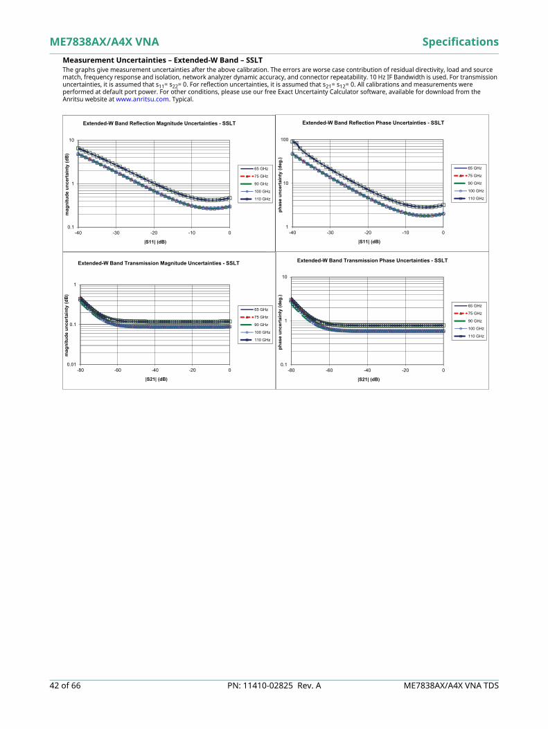
Measurement Uncertainties – Extended-E Band – SSLT The graphs give measurement uncertainties after the above calibration. The errors are worse case contribution of residual directivity, load and source match, frequency response and isolation, network analyzer dynamic accuracy, and connector repeatability. 10 Hz IF Bandwidth is used. For transmission uncertainties, it is assumed that s11= s22= 0. For reflection uncertainties, it is assumed that s21= s12= 0. All calibrations and measurements were performed at default port power. For other conditions, please use our free Exact Uncertainty Calculator software, available for download from the Anritsu web site at www.anritsu.com. Typical.
0.1
1
10
-40 -30 -20 -10 0
mag
nitu
de u
ncer
tain
ty (d
B)
|S11| (dB)
Extended-E Band Reflection Magnitude Uncertainties - SSLT
56 GHz
60 GHz
77 GHz
90 GHz
94 GHz
1
10
100
-40 -30 -20 -10 0
phas
e un
cert
aint
y (d
eg.)
|S11| (dB)
Extended-E Band Reflection Phase Uncertainties - SSLT
56 GHz
60 GHz
77 GHz
90 GHz
94 GHz
0.01
0.1
1
-80 -60 -40 -20 0
mag
nitu
de u
ncer
tain
ty (d
B)
|S21| (dB)
Extended-E Band Transmission Magnitude Uncertainties - SSLT
56 GHz
60 GHz
77 GHz
90 GHz
94 GHz
0.1
1
10
-80 -60 -40 -20 0
phas
e un
cert
aint
y (d
eg.)
|S21| (dB)
Extended-E Band Transmission Phase Uncertainties - SSLT
56 GHz
60 GHz
77 GHz
90 GHz
94 GHz
ME7838AX/A4X VNA Specifications
42 of 66 PN: 11410-02825 Rev. A ME7838AX/A4X VNA TDS
Measurement Uncertainties – Extended-W Band – SSLT The graphs give measurement uncertainties after the above calibration. The errors are worse case contribution of residual directivity, load and source match, frequency response and isolation, network analyzer dynamic accuracy, and connector repeatability. 10 Hz IF Bandwidth is used. For transmission uncertainties, it is assumed that s11= s22= 0. For reflection uncertainties, it is assumed that s21= s12= 0. All calibrations and measurements were performed at default port power. For other conditions, please use our free Exact Uncertainty Calculator software, available for download from the Anritsu website at www.anritsu.com. Typical.
0.1
1
10
-40 -30 -20 -10 0
mag
nitu
de u
ncer
tain
ty (d
B)
|S11| (dB)
Extended-W Band Reflection Magnitude Uncertainties - SSLT
65 GHz
75 GHz
90 GHz
100 GHz
110 GHz
1
10
100
-40 -30 -20 -10 0
phas
e un
cert
aint
y (d
eg.)
|S11| (dB)
Extended-W Band Reflection Phase Uncertainties - SSLT
65 GHz
75 GHz
90 GHz
100 GHz
110 GHz
0.1
1
10
-80 -60 -40 -20 0
phas
e un
cert
aint
y (d
eg.)
|S21| (dB)
Extended-W Band Transmission Phase Uncertainties - SSLT
65 GHz
75 GHz
90 GHz
100 GHz
110 GHz
0.01
0.1
1
-80 -60 -40 -20 0
mag
nitu
de u
ncer
tain
ty (d
B)
|S21| (dB)
Extended-W Band Transmission Magnitude Uncertainties - SSLT
65 GHz
75 GHz
90 GHz
100 GHz
110 GHz

Specifications ME7838AX/A4X VNA
ME7838AX/A4X VNA TDS PN: 11410-02825 Rev. A 43 of 66
Measurement Uncertainties – Extended-E Band – LRL The graphs give measurement uncertainties after the above calibration. The errors are worse case contribution of residual directivity, load and source match, frequency response and isolation, network analyzer dynamic accuracy, and connector repeatability. 10 Hz IF Bandwidth is used. For transmission uncertainties, it is assumed that s11= s22= 0. For reflection uncertainties, it is assumed that s21= s12= 0. All calibrations and measurements were performed at default port power. For other conditions, please use our free Exact Uncertainty Calculator software, available for download from the Anritsu web site at www.anritsu.com. Typical.
0.01
0.1
1
-80 -60 -40 -20 0
mag
nitu
de u
ncer
tain
ty (d
B)
|S21| (dB)
Extended-E Band Transmission Magnitude Uncertainties - LRL
56 GHz
60 GHz
77 GHz
90 GHz
94 GHz
0.1
1
10
-80 -60 -40 -20 0
phas
e un
cert
aint
y (d
eg.)
|S21| (dB)
Extended-E Band Transmission Phase Uncertainties - LRL
56 GHz
60 GHz
77 GHz
90 GHz
94 GHz
0.1
1
10
-40 -30 -20 -10 0
mag
nitu
de u
ncer
tain
ty (d
B)
|S11| (dB)
Extended-E Band Reflection Magnitude Uncertainties - LRL
56 GHz
60 GHz
77 GHz
90 GHz
94 GHz
0.1
1
10
100
-40 -30 -20 -10 0
phas
e un
cert
aint
y (d
eg.)
|S11| (dB)
Extended-E Band Reflection Phase Uncertainties - LRL
56 GHz
60 GHz
77 GHz
90 GHz
94 GHz
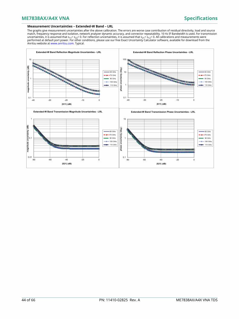
ME7838AX/A4X VNA Specifications
44 of 66 PN: 11410-02825 Rev. A ME7838AX/A4X VNA TDS
Measurement Uncertainties – Extended-W Band – LRL The graphs give measurement uncertainties after the above calibration. The errors are worse case contribution of residual directivity, load and source match, frequency response and isolation, network analyzer dynamic accuracy, and connector repeatability. 10 Hz IF Bandwidth is used. For transmission uncertainties, it is assumed that s11= s22= 0. For reflection uncertainties, it is assumed that s21= s12= 0. All calibrations and measurements were performed at default port power. For other conditions, please use our free Exact Uncertainty Calculator software, available for download from the Anritsu website at www.anritsu.com. Typical.
0.1
1
10
100
-40 -30 -20 -10 0
phas
e un
cert
aint
y (d
eg.)
|S11| (dB)
Extended-W Band Reflection Phase Uncertainties - LRL
65 GHz
75 GHz
90 GHz
100 GHz
110 GHz
0.1
1
10
-40 -30 -20 -10 0
mag
nitu
de u
ncer
tain
ty (d
B)
|S11| (dB)
Extended-W Band Reflection Magnitude Uncertainties - LRL
65 GHz
75 GHz
90 GHz
100 GHz
110 GHz
0.1
1
10
-80 -60 -40 -20 0
phas
e un
cert
aint
y (d
eg.)
|S21| (dB)
Extended-W Band Transmission Phase Uncertainties - LRL
65 GHz
75 GHz
90 GHz
100 GHz
110 GHz
0.01
0.1
1
-80 -60 -40 -20 0
mag
nitu
de u
ncer
tain
ty (d
B)
|S21| (dB)
Extended-W Band Transmission Magnitude Uncertainties - LRL
65 GHz
75 GHz
90 GHz
100 GHz
110 GHz

Specifications ME7838AX/A4X VNA
ME7838AX/A4X VNA TDS PN: 11410-02825 Rev. A 45 of 66
mmWave Noise Figure Measurements with Option 41/48 and 3744A-Rx
The 3744A-Rx receiver module can be used with Option 41, Noise Figure, and the ME7838AX/A4X VNA mmWave or broadband system to perform mmWave noise figure measurements from 30 GHz to 125 GHz. The receiver bypasses the internal couplers (see block diagram), maximizing the noise figure of the receiver for optimum noise figure measurement accuracy. The receiver is derived from the 3743AX mmWave module and utilizes the same nonlinear transmission line technology for optimum mmWave performance. Using the advantages of the 3743AX mmWave module system architecture provides a unique solution to mmWave noise figure measurements previously unavailable.With Option 48, differential (and common-mode) noise figure measurements are possible in the same wide frequency ranges. In this case, two 3744A-Rx modules (along with needed pre-amplifiers/filters) are used to complete the differential receiver. While usually a 4-port system is used, a 2-port ME7838AX can be used for the noise measurements as long as DUT gain information is available.The Rx modules are typically connected as ports 2 and 4 to act as the differential/common-mode noise receiver when used with the ME7838A4X.
ME7838AX with 3744A-Rx Receiver Module

ME7838AX/A4X VNA Specifications
46 of 66 PN: 11410-02825 Rev. A ME7838AX/A4X VNA TDS
Block Diagram – 3744A Receiver Module As with all cold source method noise figure measurements, the output of the DUT is first sent to an external composite receiver for pre-amplification. This ensures that the system noise figure is minimized for optimum measurement accuracy. The Anritsu Noise Figure Uncertainty Calculator (available on the website at www.anritsu.com can be used to determine optimum preamplifier gain needed for the desired measurement uncertainty.
3744A-Rx Receiver Compression, Noise Floor Receiver Compression Point is defined as the port power level beyond which the response may be compressed more than 0.2 dB relative to the normalization level. 10 Hz IF bandwidth is used to remove trace noise effects.Noise Floor is relative to the receiver power calibration performed at –10 dBm.
Waveguide Bands from 50 GHz to 1.1 THz Waveguide Bands from 50 GHz to 1.1 THz
The VectorStar mmWave system supports OML or VDI modules starting at 50 GHz. System performance is based on the specific mmWave module installed and appropriate cal kit. The mmWave modules need to provide IF levels of -15 dBm to -5 dBm when the RF drive is set to maximum in order to deliver specified dynamic range. Contact the vendor web site for additional information.
3744A-Rx Block Diagram(Two composite receivers and two 3744A-Rx modules are used with Option 48 for differential or common-mode noise figure measurements.)
[dBm]Frequency [GHz] Receiver Compression a
a. At the 3744A-Rx test port.
Noise Floor b
b. Excludes localized spurious responses and crosstalk.
30 to 54 GHz (0) (–124)> 54 to 60 GHz (0) (–122)> 60 to 67 GHz (0) (–117)> 67 to 80 GHz (0) (–120)> 80 to 85 GHz (0) (–123)> 85 to 90 GHz (0) (–121)> 90 to 95 GHz (0) (–121)
> 95 to 105 GHz (0) (–117)> 105 to 110 GHz (0) (–122)> 110 to 120 GHz (–5) (–120)> 120 to 125 GHz (–5) (–117)
VDI and OML mmWave Modules
Composite Receiver
DUT30 GHz - 125 GHz
3744A-Rx 30 GHz - 125 GHz Receiver Module
NonlinearTransmission Line
GaAs Sampler
LO
Test IF

Specifications ME7838AX/A4X VNA
ME7838AX/A4X VNA TDS PN: 11410-02825 Rev. A 47 of 66
VectorStar ME7838AX/A4X VNA mmWave System with VDI Modules This section provides the specifications for the VectorStar MS4640B series microwave Vector Network Analyzers (VNAs) when configured with the Virginia Diodes, Inc. mmWave frequency extension modules. The following frequency bands are supported:
System Configuration with VDI Modules The VectorStar mmWave system provides control of VDI modules for frequency extension coverage up to 1.1 THz*. MS4640B series VectorStar VNA may be configured for mmWave operation by adding the appropriate control option and test set. System requirements include:
VectorStar VNA Model MS4642B, MS4644B, or MS4647B (Note: For 1.1 THz operation the 40 GHz MS4644B or higher model is required.)
Options MS4640B Option 7, Receiver OffsetMS4640B Option 80, 81, 82, or 83
Test Set 3739C Test Set Cable SM6537 Interface Cable – Connection between VectorStar and the VDI mmWave module is provided with
this interface cable.Each VDI module is equipped with a dedicated external power supply and DC cable.
VDI Module Specifications Specifications: Dynamic range (DR) specifications are valid for any MS4640B VectorStar VNA with appropriate options.
Directivity specifications are valid when using appropriate VDI calibration kits. These specification results assume a through measurement with two TxRx Heads. All extender heads include a precision Test Port. The specifications here are typical and subject to change.
Stability: Measured for 1 hour after a 1 hour system warm-up, in a stable environment with ideal cables. Dynamic Range: The dynamic range (RBW 10 Hz) is measured by first connecting two TxRx heads together and normalizing
the un-calibrated S21 and S12. The heads are then disconnected and terminated with a waveguide short. The rms of the measured S21 & S12 give the system dynamic range.
Test Port Power: Test Port Power is typical. Reduced power is possible at band edges.
VDI Module Head Configurations TxRx Transmitter with two receivers (reference and measurement), and two couplers. Two TxRx heads are
required for full two-port measurements.TxRef Transmitter with reference receiver and one coupler.
Rx Measurement receiver.Tx Transmitter.
VDI Module Options Micrometer-Drive Variable Attenuator A 0 dB to 30 dB micrometer-drive variable attenuator option is available on TxRx and Tx modules up
through WR1.5. If ordered, "–Attn" is added as an option suffix to the module model number. The attenuators reduce TPP and DR by as much as 5dB in the WR3.4 and higher frequency bands and add approximately 2 in to the enclosure.
Increased Test Port Power Options exist for increasing test port power in some full bands or in partial bands.Consult factory for more information.
Non-Standard Frequency Bands Non-standard frequency bands or other specific needs are possible. Consult factory for more information.
Custom Configuration Anritsu/VDI will work with customers to reconfigure any extender to meet specific needs.
Waveguide Band WR15 WR10 WR8.0 WR6.5 WR5.1 WR4.3 WR3.4 WR2.8 WR2.2 WR1.5 WR1.0a
a. Contact Anritsu
Frequency [GHz] 50 to 75 75 to 110 90 to 140 110 to 170 140 to 220 170 to 260 220 to 330 260 to 400 330 to 500 500 to 750 750 to 1100
VDI Extenders-Summary of SpecificationsWaveguide Band
Frequency Coverage [GHz]
WR15
50-75
WR12
60-90
WR10
75-110
WR8.0
90-140
WR6.5
110-170
WR5.1
140-220
WR4.3
170-260
WR3.4
220-330
WR2.8
260-400
WR2.2
330-500
WR1.5
500-750
WR1.0
750-1100Dynamic Range BW = 10 Hz,
[dB], (Typical) 120 120 120 120 120 120 115 115 100 110 100 65
Dynamic Range BW = 10 Hz, [dB], minimum 110 110 110 110 110 110 110 105 80 100 80 45
Magnitude Stability[± dB] 0.15 0.15 0.15 0.15 0.25 0.25 0.3 0.3 0.5 0.5 0.4 0.5
Phase Stability [± deg.] 2 2 2 2 4 4 4 6 6 6 4 6
Test Port Power[dBm Typical] 13 13 18 6 13 6 –2 1 –10 –3 –25 –30
Test Port Input Limita (dBm, Saturation/Damage]
a. Test Port Input Limits are shown for standard test port power models only.
30 30 30 30 30 30 28 26 16 10 -3 -3
Directivity [dB] 30 30 30 30 30 30 30 30 30 30 30 30

ME7838AX/A4X VNA Specifications
48 of 66 PN: 11410-02825 Rev. A ME7838AX/A4X VNA TDS
ME7838AX/A4X VNA Measurement Examples Using VDI mmWave Modules
Typical Dynamic Range Plot of VDI WR2.2 Module – 10 Hz IFBW
Typical Dynamic Range Plot of VDI WR1.5 Dual TxRx – 10 Hz IFBW
VDI WR2.2 - VNA Extender - Dual TxRx - 10 Hz IF BW
S12S21
Dyn
amic
Ran
ge (d
B)
Frequency (GHz)325 350 375 400 425 450 475 500
140
120
100
80
60
40
20
0
0
20
40
60
80
100
120
140
500 550 600 650 700 750
Dyna
mic
Ran
ge (d
B)
Frequency (GHz)
VDI WR1.5 - Dual TxRx - 10 Hz IF BW
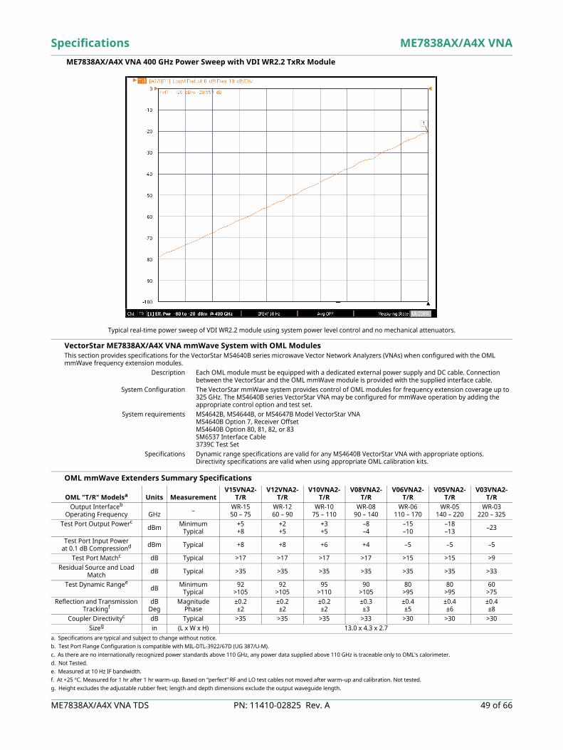
Specifications ME7838AX/A4X VNA
ME7838AX/A4X VNA TDS PN: 11410-02825 Rev. A 49 of 66
ME7838AX/A4X VNA 400 GHz Power Sweep with VDI WR2.2 TxRx Module
VectorStar ME7838AX/A4X VNA mmWave System with OML Modules This section provides specifications for the VectorStar MS4640B series microwave Vector Network Analyzers (VNAs) when configured with the OML mmWave frequency extension modules.
Description Each OML module must be equipped with a dedicated external power supply and DC cable. Connection between the VectorStar and the OML mmWave module is provided with the supplied interface cable.
System Configuration The VectorStar mmWave system provides control of OML modules for frequency extension coverage up to 325 GHz. The MS4640B series VectorStar VNA may be configured for mmWave operation by adding the appropriate control option and test set.
System requirements MS4642B, MS4644B, or MS4647B Model VectorStar VNAMS4640B Option 7, Receiver OffsetMS4640B Option 80, 81, 82, or 83SM6537 Interface Cable3739C Test Set
Specifications Dynamic range specifications are valid for any MS4640B VectorStar VNA with appropriate options. Directivity specifications are valid when using appropriate OML calibration kits.
OML mmWave Extenders Summary Specifications
Typical real-time power sweep of VDI WR2.2 module using system power level control and no mechanical attenuators.
OML "T/R" Modelsa
a. Specifications are typical and subject to change without notice.
Units MeasurementV15VNA2-
T/RV12VNA2-
T/RV10VNA2-
T/RV08VNA2-
T/RV06VNA2-
T/RV05VNA2-
T/RV03VNA2-
T/ROutput Interfaceb
Operating Frequency
b. Test Port Flange Configuration is compatible with MIL-DTL-3922/67D (UG 387/U-M).
GHz – WR-1550 – 75
WR-1260 – 90
WR-1075 – 110
WR-0890 – 140
WR-06110 – 170
WR-05140 – 220
WR-03220 – 325
Test Port Output Powerc
c. As there are no internationally recognized power standards above 110 GHz, any power data supplied above 110 GHz is traceable only to OML's calorimeter.
dBm Minimum Typical
+5+8
+2+5
+3+5
–8–4
–15–10
–18–13 –23
Test Port Input Powerat 0.1 dB Compressiond
d. Not Tested.
dBm Typical +8 +8 +6 +4 –5 –5 –5
Test Port Matchc dB Typical >17 >17 >17 >17 >15 >15 >9Residual Source and Load
Match dB Typical >35 >35 >35 >35 >35 >35 >33
Test Dynamic Rangee
e. Measured at 10 Hz IF bandwidth.
dB Minimum Typical
92>105
92>105
95>110
90>105
80>95
80>95
60>75
Reflection and Transmission Trackingf
f. At +25 °C. Measured for 1 hr after 1 hr warm–up. Based on “perfect” RF and LO test cables not moved after warm–up and calibration. Not tested.
dBDeg
Magnitude Phase
±0.2±2
±0.2±2
±0.2±2
±0.3±3
±0.4±5
±0.4±6
±0.4±8
Coupler Directivityc dB Typical >35 >35 >35 >33 >30 >30 >30Sizeg
g. Height excludes the adjustable rubber feet; length and depth dimensions exclude the output waveguide length.
in (L x W x H) 13.0 x 4.3 x 2.7

ME7838AX/A4X VNA Specifications
50 of 66 PN: 11410-02825 Rev. A ME7838AX/A4X VNA TDS
Standard Capabilities for All Configurations
For standard capabilities of the VectorStar VNAsSee the VectorStar MS4640B Series VNA Technical Data Sheet (11410-00611)
available at www.anritsu.com.

Specifications ME7838AX/A4X VNA
ME7838AX/A4X VNA TDS PN: 11410-02825 Rev. A 51 of 66
d Capabilities
Standard Capabilities for All Configurations Standard Capabilities
Mechanical and Environmental
MS4640B Vector Network Analyzer Dimensions without rack mount option.Height 267 mm body (6u)
286 mm between feet outer edgesWidth 426 mm body
457 mm between feet outer edges487 mm between front panel handles outer edges
Depth 502 mm body591 mm between handle and foot outer edges
Weight < 30 kg (< 66 lbs), Typical weight for a fully-loaded MS4647B VNA
3739C Broadband/mmWave Test Set Dimensions without rack mount option.Height 89 mm body (2u)
108 mm between feet outer edgesWidth 426 mm body
457 mm between feet outer edges487 mm between front panel handles outer edges
Depth 502 mm body591 mm between handle and foot outer edges
Weight 5.75 kg
3736B Broadband/mmWave Test Set Dimensions without rack mount optionHeight 89 mm body (2u)
108 mm between feet outer edgesWidth 426 mm body
457 mm between feet outer edges487 mm between front panel handles outer edges
Depth 502 mm body591 mm between handle and foot outer edges
Weight 5.75 kg
MN469xC Test Set Height 89 mm (3u)108 mm between feet outer edges
Width 426 mm body444 mm between feet outer edges487 mm between front panel handles outer edges
Depth 502 mm body591 mm between handle and foot outer edges
Weight < 10 kg (fully loaded)
3743AX mmWave Module Height 21.5 mmWidth 54 mmDepth 55.3 mm
Weight 0.27 kg
Environmental – Operating Conforms to MIL-PRF-28800F (Class 3)Temperature Range 0 ºC to +50 ºC without error codes
(Except for ‘unleveled’ error messages that may occur at the extreme edges of the temperature range above.)
Relative Humidity 5 % to 95 % at +30 ºC, Non-condensingAltitude 4,600 m (15,000 feet)
Environmental – Non-Operating Temperature Range –40 ºC to +71 ºC
Relative Humidity 0 % to 90 % at +30 ºC , Non-condensingAltitude 4,600 m (15,000 feet)
Regulatory Compliance European Union EMC 2014/30/EU, EN 61326:2013, CISPR 11/EN 55011, IEC/EN 61000-4-2/3/4/5/6/8/11
Low Voltage Directive 2014/35/EU Safety EN 61010-1:2010 RoHS Directive 2011/65/EU applies to instruments with CE marking placed on the market after July 22, 2017.
Canada ICES-1(A)/NMB-1(A), ICES-3(A)Australia and New Zealand RCM AS/NZS 4417:2012
South Korea KCC-REM-A21-0004
ME7838AX/A4X VNA Specifications
52 of 66 PN: 11410-02825 Rev. A ME7838AX/A4X VNA TDS
Warranty The ME7838AX/A4X VNA Series VNAs and related accessories offer a 3 year warranty from the date of shipment (excluding OML and VDI modules). Please contact your local service center for additional warranty coverage.
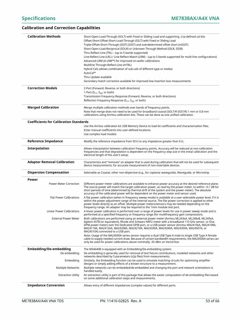
Specifications ME7838AX/A4X VNA
ME7838AX/A4X VNA TDS PN: 11410-02825 Rev. A 53 of 66
Calibration and Correction Capabilities Calibration, Verification, and Measurement
Calibration Methods Short-Open-Load-Through (SOLT) with Fixed or Sliding Load and supporting .s1p-defined cal kits Offset-Short-Offset-Short-Load-Through (SSLT) with Fixed or Sliding LoadTriple-Offset-Short-Through (SSST) (SSST) and overdetermined offset short (mSSST)Short-Open-Load-Reciprocal (SOLR) or Unknown Through Method (SSLR, SSSR) Thru-Reflect-Line (TRL) – (up to 5 bands supported)Line-Reflect-Line (LRL) / Line-Reflect-Match (LRM) – (up to 5 bands supported for multi-line configurations) Advanced-LRM (A-LRM™) for improved on-wafer calibrations Multiline Through-Reflect-Line (mTRL)Hybrid Cals (allows combination of sub-cals of different type or media)AutoCal™Thru Update availableSecondary match correction available for improved low insertion loss measurements
Correction Models 2-Port (Forward, Reverse, or both directions) 1-Port (S11, S22, or both)Transmission Frequency Response (Forward, Reverse, or both directions)Reflection Frequency Response (S11, S22, or both)
Merged Calibration Merge multiple calibration methods over bands of frequency points.Note that merge does not need to be used for broadband coaxial (SOLT/R-SSST/R) 1 mm or 0.8 mm calibrations using Anritsu calibration kits. These can be done as one unified calibration.
Coefficients for Calibration Standards Use the Anritsu calibration kit USB Memory Device to load kit coefficients and characterization files.Enter manual coefficients into user-defined locations.Use complex load models.
Reference Impedance Modify the reference impedance from 50 to any impedance greater than 0 .
Interpolation Allows interpolation between calibration frequency points. Accuracy will be reduced at non-calibration frequencies and that degradation is dependent on the frequency step size in the initial calibration and the electrical length of the user’s setup.
Adapter Removal Calibration Characterizes and “removes” an adapter that is used during calibration that will not be used for subsequent device measurements; for accurate measurement of non-insertable devices.
Dispersion Compensation Selectable as Coaxial, other non-dispersive (e.g., for coplanar waveguide), Waveguide, or Microstrip.
Power Power Meter Correction Different power meter calibrations are available to enhance power accuracy at the desired reference plane.
The source power will match the target calibration power, as read by the power meter, to within ~0.1 dB for short periods of time (determined by thermal drift of the system and the power meter). The absolute accuracy of the calibrated power will be dependent on the power meter and sensor used.
Flat Power Calibrations A flat power calibration (when in frequency sweep mode) is available at a user-selectable power level, if it is within the power adjustment range of the internal source. The flat power correction is applied to other power levels directly as an offset. Multiple power meters/sensors may be needed depending on the frequency range. An adapter may be required to the 1mm module test port.
Linear Power Calibrations A linear power calibration is performed over a range of power levels for use in power sweep mode and is performed at a specified frequency or frequency range (for multifrequency gain compression).
External Power Meter Both calibrations are performed using an external power meter (Anritsu ML243xA, ML248xB, ML249xA, Agilent 437B (or equivalent), Rhode and Schwarz NRP2 meter with a broadband 110 GHz sensor, or Elva DPM power meter) over the Dedicated GPIB port, or a USB power sensor (Anritsu MA24106A, MA24108A, MA24118A, MA24126A, MA24208A, MA24218A, MA24330A, MA24340A, MA24350A, MA24507A, or MA24510A) connected to a USB port. Note: Usage of the MA24500A series sensor requires a dual USB Type A male to single USB Type A female cable to supply needed current draw. Because of certain bandwidth requirements, the MA24500A series can only be used for power calibrations above nominally -35 dBm on VectorStar.
Embedding/De-embedding The MS4640B is equipped with an Embedding/De-embedding system. De-embedding De-embedding is generally used for removal of test fixture contributions, modeled networks and other
networks described by S-parameters (s2p files) from measurements. Embedding Similarly, the Embedding function can be used to simulate matching circuits for optimizing amplifier
designs or simply adding effects of a known structure to a measurement. Multiple Networks Multiple networks can be embedded/de-embedded and changing the port and network orientations is
handled easily. Extraction Utility An extraction utility is part of this package that allows the easier computation of de-embedding files based
on some additional calibration steps and measurements.
Impedance Conversion Allows entry of different impedances (complex values) for different ports.

ME7838AX/A4X VNA Specifications
54 of 66 PN: 11410-02825 Rev. A ME7838AX/A4X VNA TDS
Mechanical Calibration/Verification Kits
W1 1 mm Calibration/Verification Kit, 3656C Provides 12-term SOLT or Triple Offset Short calibrations, for W1 1 mm devices, and two verification standards. The standard 3656C and 3656C-3 kits include calibration and verification (18WWF50A-1 and -1B) components and verification characterization data. The3656C-5 and 3656C-6 kits include only the calibration components. 3656C-3 and 3656C-6 kits have the calibration components defined with .s1p (tabular) files as well as with the model-based .ccf files.
3656C W1 1 mm Calibration/Verification Kit providing 12-Term SOLT or SSST calibrations and two verification standards.
3656C Cal Kit Contents Additional Information (Typical) Quantity Part NumberOffset Short W1 (male) Offset: 2.020 mm 1 23W50-1Offset Short W1 (male) Offset: 2.650 mm 1 23W50-2Offset Short W1 (male) Offset: 3.180 mm 1 23W50-5
Offset Short W1 (female) Offset: 2.020 mm 1 23WF50-1Offset Short W1 (female) Offset: 2.650 mm 1 23WF50-2Offset Short W1 (female) Offset: 3.180 mm 1 23WF50-5
Open W1 (male) Offset: 1.510 mm 24W50Open W1 (female) Offset: 1.930 mm 1 24WF50
Fixed Termination W1 (male) 1 28W50Fixed Termination W1 (female) 1 28WF50
Adapter, W1 (male) to Fixed SC a Connector
a. XSC Connectors are a solution for accurate calibrations for non-insertable 1 mm devices. Users can change the gender of the SC connector using the provided tool, pin, sliders, and locking keys to ensure the best pin-depth, thus calibrations are valid after changing the gender of the adapter.
1 33WSC50Adapter, W1 (female) to Fixed SC a Connector 1 33WFSC50
Interchangeable Slider for SC a Connector (male) 1 –Interchangeable Slider for SC a Connector (female) 1 –
Locking Keys for SC a Connectors 1 –Pin Exchange Tool for SC a Connectors Contains 1 male pin 1 01-402
Adapter, W1 (male) to W1 (female) 1 33WWF50AAdapter, W1 (male) to W1 (male) 1 33WW50A
Adapter, W1 (female) to W1 (female) 1 33WFWF50AStepped Impedance Thruline, W1 (male - female) Verification Device 1 18WWF50A-1B
50 O matched Thruline, W1 (male - female) Verification Device 1 18WWF50A-1Torque Wrench 6 mm, 5.4 N·cm (4 lbf·in) 1 01-504
Open-ended Wrench 6 mm / 7 mm 1 01-505Coefficients for Standards On USB Memory Device –

Specifications ME7838AX/A4X VNA
ME7838AX/A4X VNA TDS PN: 11410-02825 Rev. A 55 of 66
Test Port Cables
Test Port Cables, Flexible, High Performance 3671W1-50-X
DescriptionFrequency
Range ImpedanceLength
[cm]Insertion Loss
[dB]Return Loss
[dB]Part
Number
W1 (1 mm) (male) toW1 (1 mm) (female) DC to 110 GHz 50
10 1.74 14 3671W1-50-113 2.23 14 3671W1-50-216 2.74 14 3671W1-50-3
3671W1-50-X Flexible Test Port Cables
3670.850-1, 3670.850-2
DescriptionFrequency
Range ImpedanceLength
[cm]Insertion Loss
[dB]Return Loss
[dB]Part
Number
1.0 mm (male)1.0 mm (female)
DC to 110 GHz (125 GHz) 50
10
(2.5 at 125 GHz) >=18 dB under 15 GHz>=16 dB for 15-50 GHz
>=12 dB for 50 to 110 GHz(>=12 dB for 110 to 125 GHz)
3670W50-1
16 (3.5 dB at 125 GHz)
>=18 dB under 15 GHz>=16 dB for 15-50 GHz
>=12 dB for 50 to 110 GHz(>=12 dB for 110 to 125 GHz)
3670W50-2
3670W50-X 1 mm Test Port Cables

ME7838AX/A4X VNA Specifications
56 of 66 PN: 11410-02825 Rev. A ME7838AX/A4X VNA TDS
Precision Adapters, Attenuators, and Other Components Anritsu offers a complete line of precision adapters and attenuators. For more information, please visit our web site at www.anritsu.com.
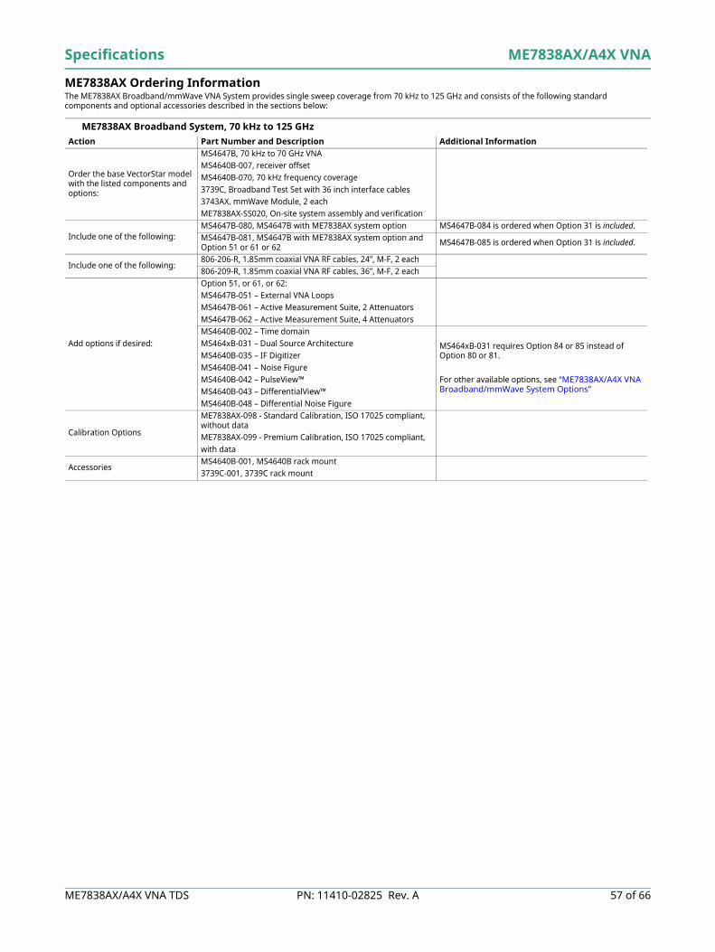
Specifications ME7838AX/A4X VNA
ME7838AX/A4X VNA TDS PN: 11410-02825 Rev. A 57 of 66
ME7838AX Ordering Information The ME7838AX Broadband/mmWave VNA System provides single sweep coverage from 70 kHz to 125 GHz and consists of the following standard components and optional accessories described in the sections below:
ME7838AX Broadband System, 70 kHz to 125 GHz Action Part Number and Description Additional Information
Order the base VectorStar model with the listed components and options:
MS4647B, 70 kHz to 70 GHz VNAMS4640B-007, receiver offsetMS4640B-070, 70 kHz frequency coverage3739C, Broadband Test Set with 36 inch interface cables3743AX, mmWave Module, 2 eachME7838AX-SS020, On-site system assembly and verification
Include one of the following:MS4647B-080, MS4647B with ME7838AX system option MS4647B-084 is ordered when Option 31 is included.MS4647B-081, MS4647B with ME7838AX system option and Option 51 or 61 or 62 MS4647B-085 is ordered when Option 31 is included.
Include one of the following:806-206-R, 1.85mm coaxial VNA RF cables, 24”, M-F, 2 each806-209-R, 1.85mm coaxial VNA RF cables, 36”, M-F, 2 each
Add options if desired:
Option 51, or 61, or 62:MS4647B-051 – External VNA LoopsMS4647B-061 – Active Measurement Suite, 2 AttenuatorsMS4647B-062 – Active Measurement Suite, 4 AttenuatorsMS4640B-002 – Time domainMS464xB-031 – Dual Source ArchitectureMS4640B-035 – IF DigitizerMS4640B-041 – Noise FigureMS4640B-042 – PulseView™MS4640B-043 – DifferentialView™MS4640B-048 – Differential Noise Figure
MS464xB-031 requires Option 84 or 85 instead of Option 80 or 81.
For other available options, see “ME7838AX/A4X VNA Broadband/mmWave System Options”
Calibration Options
ME7838AX-098 - Standard Calibration, ISO 17025 compliant, without dataME7838AX-099 - Premium Calibration, ISO 17025 compliant,with data
AccessoriesMS4640B-001, MS4640B rack mount3739C-001, 3739C rack mount

ME7838AX/A4X VNA Specifications
58 of 66 PN: 11410-02825 Rev. A ME7838AX/A4X VNA TDS
ME7838AX Waveguide-Band System to 110 GHz – 3744A-EE or 3744A-EW mmWave Modules Configurator for ME7838AX mmWave System using 3744A-EE or 3744A-EW mmWave Modules:
Action Part Number and Description Additional Information
Choose and order one of the two base VectorStar models with options listed:
MS4644B VNA, 10 MHz to 40 GHzMS4640B-007MS4644B-082 or MS4644B-083
MS4644B-083 is ordered when Option 51, or 61, or 62 is included.MS4644B-084 is ordered when Option 31 is included and Option 51, or 61, or 62 is excluded.MS4644B-085 is ordered when Option 31 and Option 51, or 61, or 62 is included.
MS4647B VNA, 10 MHz to 70 GHzMS4647B-007MS4647B-080 or MS4647B-081
MS4647B-081 is ordered when Option 51, or 61, or 62 is included.MS4647B-084 is ordered when Option 31 is included and Option 51, or 61, or 62 is excluded.MS4647B-085 is ordered when Option 31 and Option 51, or 61, or 62 is included.
Order Test Set 3739C mmWave Test SetChoose and order Extended-E or Extended-W Band Modules:
3744A-EE, 56 GHz to 94 GHz Extended E Band module, 2 each3744A-EW, 65 GHz to 110 GHz Extended W Band module, 2 each
Add options if desired:
Option 51, or 61, or 62:MS464xB-051 – External VNA LoopsMS464xB-061 – Active Measurement Suite, 2 AttenuatorsMS464xB-062 – Active Measurement Suite, 4 AttenuatorsMS4640B-070 – for 70 kHz operation in base VNAMS4640B-002 – for Time DomainMS464xB-031 – Dual Source ArchitectureMS4640B-035 – IF DigitizerMS4640B-041 – Noise FigureMS4640B-042 – PulseView™MS4640B-043 – DifferentialView™MS4640B-048 – Differential Noise Figure
MS464xB-031 requires Option 84 or 85 instead of Option 80 or 81.
For other available options, see “ME7838AX/A4X VNA Broadband/mmWave System Options”
MS4640B-001, MS4640B Rack Mount3739C-001, 3739C Rack MountME7838AX Waveguide-Band System with OML/VDI Modules
Accessories
35WR12WF-EE – Precision Waveguide to Coax Adapter Kit, 56 GHz to 94 GHz, WR-12 to W1 (f)35WR10WF-EW – Precision Waveguide to Coax Adapter Kit, 65 GHz to 110 GHz, WR-10 to W1 (f)
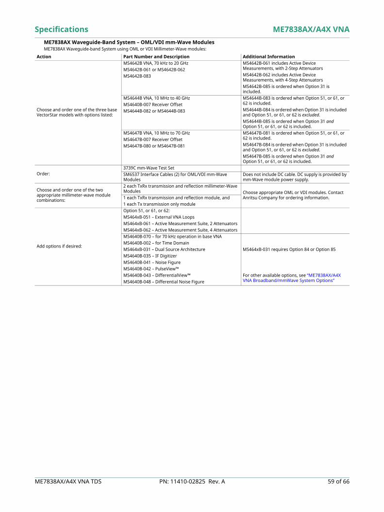
Specifications ME7838AX/A4X VNA
ME7838AX/A4X VNA TDS PN: 11410-02825 Rev. A 59 of 66
ME7838AX Waveguide-Band System – OML/VDI mm-Wave Modules ME7838AX Waveguide-band System using OML or VDI Millimeter-Wave modules:
Action Part Number and Description Additional Information
Choose and order one of the three base VectorStar models with options listed:
MS4642B VNA, 70 kHz to 20 GHz MS4642B-061 or MS4642B-062MS4642B-083
MS4642B-061 includes Active Device Measurements, with 2-Step Attenuators MS4642B-062 includes Active Device Measurements, with 4-Step AttenuatorsMS4642B-085 is ordered when Option 31 is included.
MS4644B VNA, 10 MHz to 40 GHzMS4640B-007 Receiver OffsetMS4644B-082 or MS4644B-083
MS4644B-083 is ordered when Option 51, or 61, or 62 is included.MS4644B-084 is ordered when Option 31 is included and Option 51, or 61, or 62 is excluded.MS4644B-085 is ordered when Option 31 and Option 51, or 61, or 62 is included.
MS4647B VNA, 10 MHz to 70 GHzMS4647B-007 Receiver OffsetMS4647B-080 or MS4647B-081
MS4647B-081 is ordered when Option 51, or 61, or 62 is included.MS4647B-084 is ordered when Option 31 is included and Option 51, or 61, or 62 is excluded.MS4647B-085 is ordered when Option 31 and Option 51, or 61, or 62 is included.
Order:3739C mm-Wave Test SetSM6537 Interface Cables (2) for OML/VDI mm-Wave Modules
Does not include DC cable. DC supply is provided by mm-Wave module power supply.
Choose and order one of the two appropriate millimeter-wave module combinations:
2 each TxRx transmission and reflection millimeter-Wave Modules Choose appropriate OML or VDI modules. Contact
Anritsu Company for ordering information.1 each TxRx transmission and reflection module, and1 each Tx transmission only module
Add options if desired:
Option 51, or 61, or 62:MS464xB-051 – External VNA LoopsMS464xB-061 – Active Measurement Suite, 2 AttenuatorsMS464xB-062 – Active Measurement Suite, 4 AttenuatorsMS4640B-070 – for 70 kHz operation in base VNAMS4640B-002 – for Time DomainMS464xB-031 – Dual Source ArchitectureMS4640B-035 – IF DigitizerMS4640B-041 – Noise FigureMS4640B-042 – PulseView™MS4640B-043 – DifferentialView™MS4640B-048 – Differential Noise Figure
MS464xB-031 requires Option 84 or Option 85
For other available options, see “ME7838AX/A4X VNA Broadband/mmWave System Options”

ME7838AX/A4X VNA Specifications
60 of 66 PN: 11410-02825 Rev. A ME7838AX/A4X VNA TDS
ME7838A4X Ordering Information The ME7838A4X 4-Port Broadband/mmWave VNA System provides single sweep coverage from 70 kHz to 125 GHz and consists of the following standard components and optional accessories described in the sections below:
ME7838A4X 4-Port Broadband System, 70 kHz to 125 GHz
ME7838A4X 4-Port Waveguide-Band System to 110 GHz – 3744A-EE or 3744A-EW mmWave Modules Configurator for ME7838A4X mmWave System using 3744A-EE or 3744A-EW mmWave Modules:
Action Part Number and Description Additional Information
Order the base VectorStar model with the listed components and options:
MS4647B, 70 kHz to 70 GHz VNAMS4640B-007, receiver offsetMS4640B-070, 70 kHz frequency coverageMN4697C, 4-Port Test Set3739C, Broadband Test Set with 36 inch interface cables3736B Broadband/mmWave Test Set3743AX, mmWave Module, 4 each806-209-R, 1.85mm coaxial VNA RF cables, 36 in, (m-f), 4 eachME7838A4X-SS020, On-site system assembly and verification
Include the following:
MS4647B-081, MS4647B with ME7838A4X system option and Option 51, or 61, or 62:MS4647B-051 – External VNA LoopsMS4647B-061 – Active Measurement Suite, 2 AttenuatorsMS4647B-062 – Active Measurement Suite, 4 Attenuators
MS4647B-085 is ordered when Option 31 is included.
Add options if desired
MS4640B-070 – for 70 kHz operation in base VNAMS4640B-002 – for Time DomainMS464xB-031 – Dual Source ArchitectureMS4640B-035 – IF DigitizerMS4640B-041 – Noise FigureMS4640B-042 – PulseView™MS4640B-043 – DifferentialView™MS4640B-048 – Differential Noise Figure
MS464xB-031 requires Option 85
For other available options, see “ME7838AX/A4X VNA Broadband/mmWave System Options”
Calibration Options
ME7838A4X-098 - Standard Calibration, ISO 17025 compliant,without dataME7838A4X-099 - Premium Calibration, ISO 17025 compliant,with data
Action Part Number and Description Additional Information
Choose and order one of the two base VectorStar models with options listed:
MS4644B VNA, 10 MHz to 40 GHzMS4640B-007MS4644B-083 or MS4644B-085
MS4644B-085 is ordered when Option 31 is included.
MS4647B VNA, 10 MHz to 70 GHzMS4647B-007MS4647B-081 or MS4647B-085
MS4647B-085 is ordered when Option 31 is included.
Order:MN4697C, 4-Port Test Set3736B Broadband/mmWave Test Set3739C Broadband/mmWave Test Set
Choose and order Extended-E or Extended-W Band Modules:
3744A-EE, 56 GHz to 94 GHz Extended E Band module, 4 each If you order the 3744A-EE, then you can get the EW adapter kit to allow conversion of the module to both bands.3744A-EW, 65 GHz to 110 GHz Extended W Band module, 4 each
Order one of the following:
Option 51, or 61, or 62:MS464xB-051 – External VNA LoopsMS464xB-061 – Active Measurement Suite, 2 AttenuatorsMS464xB-062 – Active Measurement Suite, 4 Attenuators
ME7838A4X requires Option 51, or 61, or 62
Add options if desired:
MS4640B-070 – for 70 kHz operation in base VNAMS4640B-002 – for Time DomainMS464xB-031 – Dual Source ArchitectureMS4640B-035 – IF DigitizerMS4640B-041 – Noise FigureMS4640B-042 – PulseView™MS4640B-043 – DifferentialView™MS4640B-048 – Differential Noise Figure
MS464xB-031 requires Option 85
For other available options, see “ME7838AX/A4X VNA Broadband/mmWave System Options”
Accessories
35WR12WF-EE – Precision Waveguide to Coax Adapter Kit, 56 GHz to 94 GHz, WR-12 to W1 (f)35WR10WF-EW – Precision Waveguide to Coax Adapter Kit, 65 GHz to 110 GHz, WR-10 to W1 (f)

Specifications ME7838AX/A4X VNA
ME7838AX/A4X VNA TDS PN: 11410-02825 Rev. A 61 of 66
ME7838A4X 4-Port Waveguide-Band System – OML/VDI mmWave Modules ME7838A4X 4-Port Waveguide-Band System using OML or VDI mmWave modules:
Action Part Number and Description Additional Information
Choose and order one of the three base VectorStar models with options listed:
MS4642B VNA, 70 kHz to 20 GHz MS4642B-061 or MS4642B-062MS4642B-083
MS4642B-061 includes Active Device Measurements, with 2 Step AttenuatorsMS4642B-062 includes Active Device Measurements, with 4 Step AttenuatorsMS4642B-085 is ordered when Option 31 is included.
MS4644B VNA, 10 MHz to 40 GHzMS4640B-007 Receiver OffsetMS4644B-083
MS4644B-085 is ordered when Option 31 is included.
MS4647B VNA, 10 MHz to 70 GHzMS4640B-007 Receiver OffsetMS4647B-081
MS4647B-085 is ordered when Option 31 is included.
Order:
MN469xC, 4-port Test Set3739C Broadband/mmWave Test Set3736B Broadband/mmWave Test SetSM6537 Interface Cables (4) for OML/VDI mmWave Modules
Does not include DC cable. DC supply is provided by mmWave module power supply.
Choose and order one of the two appropriate mmWave module combinations:
4 each TxRx transmission and reflection mmWave modules Choose appropriate OML or VDI modules. Contact Anritsu Company for ordering information.
For MS4644B or MS4647B, order:
Option 51, or 61, or 62:MS464xB-051 – External VNA LoopsMS464xB-061 – Active Measurement Suite, 2 AttenuatorsMS464xB-062 – Active Measurement Suite, 4 Attenuators
ME7838A4X requires Option 51, or 61, or 62
Add options if desired:
MS4640B-070 – for 70 kHz operation in base VNAMS4640B-002 – for Time DomainMS464xB-031 – Dual Source ArchitectureMS4640B-035 – IF DigitizerMS4640B-041 – Noise FigureMS4640B-042 – PulseView™MS4640B-043 – DifferentialView™MS4640B-048 – Differential Noise Figure
MS464xB-031 requires Option 85
For other available options, see “ME7838AX/A4X VNA Broadband/mmWave System Options”

ME7838AX/A4X VNA Specifications
62 of 66 PN: 11410-02825 Rev. A ME7838AX/A4X VNA TDS
Calibration and Verification Kits Ordering Information
Calibration/Verification Kits 3656C W1 (1 mm) Calibration/Verification Kit
3656C-3 W1 (1 mm) Calibration/Verification Kit, With .s1p Characterization Files3656C-5 W1 (1 mm) Calibration Kit3656C-6 W1 (1 mm) Calibration Kit, With .s1p Characterization Files
3655V WR-15 Waveguide Calibration Kit, Without Sliding Loads3655V-1 WR-15 Waveguide Calibration Kit, With Sliding Loads
3655E WR-12 Waveguide Calibration Kit, Without Sliding Loads3655E-1 WR-12 Waveguide Calibration Kit, With Sliding Loads
3655W WR-10 Waveguide Calibration Kit, Without Sliding Loads3655W-1 WR-10 Waveguide Calibration Kit, With Sliding Loads
3650A SMA/3.5 mm Calibration Kit, Without Sliding Loads3650A-1 SMA/3.5 mm Calibration Kit, With Sliding Loads
3652A K Calibration Kit, With Pin Depth Gauge3652A-2 K Calibration Kit, With No Pin Depth Gauge3652A-3 K Calibration Kit, With Pin Depth Gauge and .s1p Characterization Files3652A-4 K Calibration Kit, With .s1p Characterization Files
3654D V Calibration Kit, With Pin Depth Gauge3654D-2 V Calibration Kit, With No Pin Depth Gauge3654D-3 V Calibration Kit, With Pin Depth Gauge and .s1p Characterization Files3654D-4 V Calibration Kit, With .s1p Characterization Files
3657 V Multi-Line Calibration Kit, Without Shorts3657-1 V Multi-Line Calibration Kit, With Shorts
External Power Meters/Sensors ML243xA CW Power Meter, Single Input or Dual Input
Recommended Power Sensors:• SC7770• MA247xD• MA244xD• MA248xD• MA2400xA
ML248xB Wideband Power Meter, Single Input or Dual InputRecommended Power Sensors:• MA249xA• MA2411B
ML249xA Pulse Power Meter, Single Input or Dual InputRecommended Power Sensors:• MA249xA• MA2411B
MA24106A USB Power Sensor, 50 MHz to 6 GHz MA24108A USB Power Sensor, 10 MHz to 8 GHz MA24118A USB Power Sensor, 10 MHz to 18 GHz MA24126A USB Power Sensor, 10 MHz to 26 GHz MA24330A USB Power Sensor, 10 MHz to 33 GHzMA24340A USB Power Sensor, 10 MHz to 40 GHzMA24350A USB Power Sensor, 10 MHz to 50 GHzMA24507A Power Master™ Frequency Selectable mmWave Power Analyzer, 9 kHz to 70 GHzMA24510A Power Master Frequency Selectable mmWave Power Analyzer, 9 kHz to110 GHz
Note that usage of the MA24507A or MA24510A Power Master sensor requires connection to two USB ports to supply needed current draw.
Test Port Cables, Flexible, High Performance 3671W1-50-1 W1 (male) to W1 (female), 1 each, 10.0 cm (3.9 in)3671W1-50-2 W1 (male) to W1 (female), 1 each, 13.0 cm (5.1 in)3671W1-50-3 W1 (male) to W1 (female), 1 each, 16.0 cm (6.3 in)
3671KFS50-60 K (female) to 3.5 mm (male) cable, 60 cm (one cable) 3671KFK50-60 K (female) to K (male) cable, 60 cm (one cable)
3671KFK50-100 K (female) to K (male) cable, 1 each, 100 cm (one cable) 3671KFKF50-60 K (female) to K (female) cable, 1 each, 60 cm (once cable)
3671VFV50-60 V (female) to V (male) cable, 1 each, 60 cm (one cable) 3671VFV50-100 V (female) to V (male) cable, 1 each, 100 cm (one cable 3671KFSF50-60 K (female) to 3.5 mm (female) cable, 1 each, 60 cm (one cable) 3671VFVF50-60 V (female) to V (female) cable, 1 each, 60 cm (one cable)

Specifications ME7838AX/A4X VNA
ME7838AX/A4X VNA TDS PN: 11410-02825 Rev. A 63 of 66
Adapters 34WV50 W1 (male) to V (male) Adapter, W1 (1 mm) to V, Coaxial
34WVF50 W1 (male) to V (female) Adapter, W1 (1 mm) to V, Coaxial34WFV50 W1 (female) to V (male) Adapter, W1 (1 mm) to V, Coaxial
34WFVF50 W1 (female) to V (female) Adapter, W1 (1 mm) to V, Coaxial33WW50A W1 (male) to W1 (male) Adapter, W1 (1 mm) in-series, Coaxial
33WWF50A W1 (male) to W1 (female) Adapter, W1 (1 mm) in-series, Coaxial33WFWF50A W1 (female) to W1 (female) Adapter, W1 (1 mm) in-series, Coaxial
35WR10W WR10 to W1 (male) Adapter, W1 (1mm) to WR10 Waveguide35WR10WF WR10 to W1 (female) Adapter, W1 (1mm) to WR10 Waveguide
SC7260 WR12 to W1 (male) Adapter, W1 (1 mm) to WR12 WaveguideSC7442 WR12 to W1 (female) Adapter, W1 (1 mm) to WR12 Waveguide
35WR15V WR15 to V (male) Adapter, V (1.85mm) to WR15 Waveguide35WR15VF WR15 to V (female) Adapter, V (1.85mm) to WR15 Waveguide
For More Information Refer to our Precision RF & Microwave Components Catalog for descriptions of adapters and other components.
Miscellaneous Components 41W-3 Attenuator, DC to 110 GHz, 0.2 W, 3 dB, W1(m) to W1(f), 50 Ω41W-6 Attenuator, DC to 110 GHz, 0.2 W, 6 dB, W1(m) to W1(f), 50 Ω
41W-10 Attenuator, DC to 110 GHz, 0.2 W, 10 dB, W1(m) to W1(f), 50 ΩW240A Precision Power Divider, DC to 110 GHz, W1(f) input, W1(f) outputs, 3 resistor, 50 ΩW241A Precision Power Splitter, DC to 110 GHz, W1(m) input, W1(f) outputs, 2 resistor, 50 Ω
MN25110A Precision Directional Coupler, 20 GHz to 110 GHz, W1(f) input, W1(f) output, W1(f) coupled port, 50 Ω
Accessories SC8215 Kelvin Bias Tee, low frequency limit: 70 kHz, Max Voltage: 16 VDC, Max Current: 100 mASC7287 Kelvin Bias Tee, low frequency limit: 100 MHz, Max Voltage: 50 VDC, Max Current: 500 mASC8218 Triax (male) to SMC (female) Cable, (Inner-shield floating at SMC end), 1.5 m (60 in) long
two (2) needed per Kelvin Bias TeeSM6494 System floor console. Includes larger size writing table
2100-1-R GPIB cable, 1 m (39 in) long2100-2-R GPIB cable, 2 m (79 in) long2100-4-R GPIB cable, 4 m (157 in) long
806-206-R Flexible Coaxial Cable, DC to 70 GHz, 24 in (61 cm), V(m) - V(f), 50Ωfor connecting the VNA and the 3743AX Modules
806-209-R Flexible Coaxial Stable Cable, DC to 70 GHz, 36in (91.5 cm), V(m) - V(f), 50Ωfor connecting the VNA and the 3743AX Modules
01-201 Torque Wrench (for tightening male devices), 8 mm (5/16 in), 0.9 N·m (8 lbf·in)for SMA, 3.5 mm, 2.4 mm, K and V connectors
01-202 Universal Test Port Connector Wrench01-203 Torque Wrench (for tightening the VNA test ports to female devices)
20.6 mm (13/16 in), 0.9 N·m (8 lbf·in)01-204 Anritsu Stainless Steel Connector Wrench, circular, open-ended
for SMA, 3.5 mm, 2.4 mm, K and V connectors01-504 Torque wrench (for tightening male devices) 6 mm, 0.45 N-m (4 lbf-in) for 1.0 mm and 0.8 mm connectors01-524 Low profile Torque Wrench (for tightening male devices), 6 mm, 0.45 N-m (4 lbf-in), 126 mm long for 1.0 mm
and 0.8 mm connectors01-529-R Torque Wrench, 4 mm (5/32 in), 0.17 N·m (1.5 lbf·in)
(for tightening the test and reference IF connectors on the mmWave modules)
ME7838AX/A4X VNA Specifications
64 of 66 PN: 11410-02825 Rev. A ME7838AX/A4X VNA TDS
Notes
Specifications ME7838AX/A4X VNA
ME7838AX/A4X VNA TDS PN: 11410-02825 Rev. A 65 of 66

ME7838AX/A4X VNA TDS, PN: 11410-02825, Rev. ACopyright October 2021, Anritsu Company, USA. All Rights Reserved.
® Anritsu All trademarks are registered trademarks of their respective companies.Anritsu utilizes recycled paper and environmentally conscious inks and toner.
Data subject to change without notice.For the most recent specifications, visit: www.anritsu.com.6666 of 66
Training at AnritsuAnritsu has designed courses to help you stay up to date with technologies important to your job. For available training courses, visit: www.anritsu.com/training
• United StatesAnritsu Americas Sales Company450 Century Parkway, Suite 190, Allen, TX 75013, U.S.A.Phone: +1-800-Anritsu (1-800-267-4878)
• CanadaAnritsu Electronics Ltd.700 Silver Seven Road, Suite 120, Kanata, Ontario K2V 1C3, CanadaPhone: +1-613-591-2003Fax: +1-613-591-1006
• BrazilAnritsu Eletronica Ltda.Praça Amadeu Amaral, 27 - 1 Andar01327-010 - Bela Vista - Sao Paulo - SP, BrazilPhone: +55-11-3283-2511Fax: +55-11-3288-6940
• MexicoAnritsu Company, S.A. de C.V.Blvd Miguel de Cervantes Saavedra #169 Piso 1, Col. Granada, Mexico, Ciudad de Mexico,11520, MEXICOPhone: +52-55-4169-7104
• United KingdomAnritsu EMEA Ltd.200 Capability Green, Luton, Bedfordshire, LU1 3LU, U.K.Phone: +44-1582-433200Fax: +44-1582-731303
• FranceAnritsu S.A.12 avenue du Québec, Immeuble Goyave,91140 VILLEBON SUR YVETTE, FrancePhone: +33-1-60-92-15-50
• GermanyAnritsu GmbHNemetschek Haus, Konrad-Zuse-Platz 1,81829 München, GermanyPhone: +49-89-442308-0Fax: +49-89-442308-55
• ItalyAnritsu S.r.l.Spaces Eur Arte, Viale dell’Arte 25, 00144 Roma, ItalyPhone: +39-6-509-9711
• SwedenAnritsu ABKistagången 20 B, 2 tr, 164 40 Kista, SwedenPhone: +46-8-534-707-00
• FinlandAnritsu ABTechnopolis Aviapolis, Teknobulevardi 3-5 (D208.5.),FI-01530 Vantaa, FinlandPhone: +358-20-741-8100
• DenmarkAnritsu A/Sc/o Regus Winghouse, Ørestads Boulevard 73, 4th floor, 2300 Copenhagen S, DenmarkPhone: +45-7211-2200
• RussiaAnritsu EMEA Ltd.Representation Office in RussiaTverskaya str. 16/2, bld. 1, 7th floor,Moscow 125009, RussiaPhone: +7-495-363-1694Fax: +7-495-935-8962
• SpainAnritsu EMEA Ltd.Representation Office in SpainPaseo de la Castellana, 141. Planta 5, Edificio Cuzco IV28046, Madrid, SpainPhone: +34-91-572-6761
• AustriaAnritsu EMEA GmbHAm Belvedere 10, A-1100 Vienna, AustriaPhone: +43-(0)1-717-28-710
• United Arab EmiratesAnritsu EMEA Ltd.Anritsu A/SOffice No. 164, Building 17, Dubai Internet CityP. O. Box – 501901, Dubai, United Arab EmiratesPhone: +971-4-3758479
• IndiaAnritsu India Private Limited6th Floor, Indiqube ETA, No.38/4, Adjacent to EMC2, Doddanekundi, Outer Ring Road, Bengaluru – 560048, IndiaPhone: +91-80-6728-1300Fax: +91-80-6728-1301
• SingaporeAnritsu Pte. Ltd.11 Chang Charn Road, #04-01, Shriro HouseSingapore 159640Phone: +65-6282-2400Fax: +65-6282-2533
• VietnamAnritsu Company Limited16th Floor, Peakview Tower, 36 Hoang Cau Street, O Cho Dua Ward, Dong Da District, Hanoi, VietnamPhone: +84-24-3201-2730
• P.R. China (Shanghai)Anritsu (China) Co., Ltd.Room 2701-2705, Tower A, New CaohejingInternational Business Center No. 391 Gui Ping RoadShanghai, 200233, P.R. ChinaPhone: +86-21-6237-0898Fax: +86-21-6237-0899
• P.R. China (Hong Kong)Anritsu Company Ltd.Unit 1006-7, 10/F., Greenfield Tower, Concordia Plaza,No. 1 Science Museum Road, Tsim Sha Tsui East, Kowloon, Hong Kong, P.R. ChinaPhone: +852-2301-4980Fax: +852-2301-3545
• JapanAnritsu Corporation8-5, Tamura-cho, Atsugi-shi, Kanagawa, 243-0016 JapanPhone: +81-46-296-6509Fax: +81-46-225-8352
• South KoreaAnritsu Corporation, Ltd.5FL, 235 Pangyoyeok-ro, Bundang-gu, Seongnam-si,Gyeonggi-do 13494, South KoreaPhone: +82-31-696-7750Fax: +82-31-696-7751
• AustraliaAnritsu Pty. Ltd.Unit 20, 21-35 Ricketts Road,Mount Waverley, Victoria 3149, AustraliaPhone: +61-3-9558-8177Fax: +61-3-9558-8255
• TaiwanAnritsu Company Inc.7F, No. 316, Sec. 1, NeiHu Rd., Taipei 114, TaiwanPhone: +886-2-8751-1816Fax: +886-2-8751-1817
List Revision Date: 20210610


