Download - Huawei umts o&m planning and configuration

Chapter 1 About This Manual 1-1.........................................................................
1.1 Objective 1-1................................................................................................1.2 Intended Readers 1-1...................................................................................
1.2.1 Role 1-1................................................................................................1.2.2 Background Knowledge Requirement 1-1...........................................
1.3 Scope of This Manual 1-1.............................................................................1.4 Organization of This Manual 1-1..................................................................
Chapter 2 Huawei UMTS O&M System 2-1..........................................................
2.1 Overview of This Chapter 2-1.......................................................................2.2 Huawei UMTS System 2-1...........................................................................
2.2.1 UMTS Network Structure 2-1...............................................................2.2.2 Huawei UMTS Devices 2-1..................................................................
2.3 M2000 2-2....................................................................................................2.3.1 Overview of M2000 2-2........................................................................2.3.2 Networking Diagram 2-2......................................................................2.3.3 IP Address Requirement 2-3................................................................2.3.4 Physical Port Requirement 2-3............................................................2.3.5 Utilized TCP/UDP Port Numbers 2-3...................................................
2.4 O&M of CN-PS Devices 2-4.........................................................................2.4.1 Structure of the CN-PS Network 2-4....................................................2.4.2 SGSN9810 2-5.....................................................................................2.4.3 GGSN9811 2-6....................................................................................2.4.4 CG9812 2-7..........................................................................................
2.5 O&M of CN-CS Devices 2-8.........................................................................2.5.1 Structure of the CN-CS Network 2-8....................................................2.5.2 MSOFTX3000 2-9................................................................................2.5.3 UMG8900 2-11.......................................................................................2.5.4 HLR9820 2-12........................................................................................2.5.5 SIWF 2-14..............................................................................................
2.6 O&M of RAN Devices 2-15.............................................................................2.6.1 Structure of the Radio Access Network 2-15.........................................2.6.2 BSC6800 2-15........................................................................................2.6.3 BTS3812/3806/3806A/3802C 2-16........................................................2.6.4 RNC-NodeB Maintenance Channel 2-18...............................................
2.7 Huawei UMTS O&M Network 2-21.................................................................2.7.1 Logical Topology of Huawei UMTS O&M Network 2-21........................2.7.2 Centralized Network Management System 2-21....................................2.7.3 Local Maintenance System 2-22............................................................
2.8 IP Bearer Modes for O&M Networks 2-22......................................................

2.8.1 Introduction to IP Bearer Modes 2-22....................................................2.8.2 Bandwidth Requirement 2-22.................................................................2.8.3 LAN 2-23................................................................................................2.8.4 WAN over E1/T1 2-24............................................................................2.8.5 WAN over DDN/X.25 Network 2-25.......................................................
Chapter 3 Huawei Security Solutions to UMTS O&M Network 3-1....................
3.1 Overview of the Security Solutions 3-1.........................................................3.2 Security Requirements for the O&M Network 3-1........................................
3.2.1 Overview of the Security Requirements 3-1.........................................3.2.2 Guaranteeing Normal Operation of the O&M Network 3-1..................3.2.3 Guaranteeing O&M Data Security 3-2.................................................
3.3 Security Solutions to Huawei O&M Network 3-2..........................................3.3.1 Features of the Security Solutions 3-2.................................................3.3.2 Introduction to Security Zone 3-3.........................................................3.3.3 Security Zone Classification Principles 3-4..........................................3.3.4 Firewall Deployment and Configuration 3-4.........................................3.3.5 Virus Protection Settings 3-5................................................................3.3.6 Antivirus Software Deployment Schemes 3-7......................................3.3.7 Antivirus Software Updates 3-9............................................................
Chapter 4 O&M Network Planning 4-1.................................................................
4.1 Overview of O&M Network Planning 4-1......................................................4.2 Basic Principles of O&M Network Planning 4-1............................................
4.2.1 Security Principles 4-1.........................................................................4.2.2 Cost-Saving Principle 4-2.....................................................................4.2.3 Expandability Principle 4-2...................................................................
4.3 Flow of O&M Network Planning 4-3.............................................................4.3.1 Understanding UMTS Network Information 4-3...................................4.3.2 Determining IP Bearing Networking 4-3...............................................4.3.3 Determining O&M Network Structure 4-4.............................................4.3.4 Determining IP Addresses for Nodes 4-5.............................................4.3.5 Determining IP Routes 4-6...................................................................4.3.6 Determining Firewall Configuration 4-6................................................
Chapter 5 O&M Network Examples 5-1................................................................
5.1 About This Chapter 5-1................................................................................5.2 UMTS O&M Network Connected into a LAN 5-1..........................................
5.2.1 Overview of the Connection 5-1...........................................................5.2.2 Network Configuration 5-1...................................................................5.2.3 Planning Network Structure 5-2...........................................................5.2.4 Planning IP Addresses 5-3...................................................................

5.2.5 Configuring IP Routes 5-4....................................................................5.3 UMTS O&M Network Connected into a WAN 5-4........................................
5.3.1 Overview of the Connection 5-4...........................................................5.3.2 Network Configuration 5-4...................................................................5.3.3 Planning Network Structure 5-5...........................................................5.3.4 Allocating IP Addresses to the O&M Devices in the WAN 5-6.............5.3.5 Planning Addresses for CN 5-7............................................................5.3.6 Configuring IP Routes for CN 5-8........................................................5.3.7 Planning IP Addresses for RAN 5-9.....................................................5.3.8 Configuring IP Routes for RAN 5-10......................................................
5.4 Example of RNC-NodeB Maintenance Channel Networking 5-11.................5.4.1 Overview of the RNC-NodeB Maintenance ChannelNetworking 5-11..............................................................................................5.4.2 Network Configuration 5-11...................................................................5.4.3 Planning IP Addresses 5-11...................................................................5.4.4 Configuring IP Routes 5-13....................................................................
Chapter 6 Background Knowledge Requirements 6-1.......................................
6.1 Overview of the Background Knowledge Requirements 6-1........................6.2 IP Network Related Fundamentals 6-1.........................................................
6.2.1 IP Address 6-1.....................................................................................6.2.2 IP Routes 6-4.......................................................................................6.2.3 TCP/UDP Port Numbers 6-4................................................................6.2.4 VLAN 6-5..............................................................................................
6.3 SetWin2000 6-5............................................................................................6.3.1 Overview of SetWin2000 6-5...............................................................6.3.2 Functions of SetWin2000 6-5...............................................................6.3.3 Operating Environment Requirements 6-6...........................................
6.4 SysPatron 6-6...............................................................................................6.4.1 Overview of SysPatron 6-6..................................................................6.4.2 Functions of SysPatron 6-6..................................................................6.4.3 Composition of SysPatron 6-7.............................................................6.4.4 Operating Environment Requirements 6-7...........................................
Appendix Acronyms and Abbreviations F-1.......................................................
Index .................................................................................................................

HUAWEI
HUAWEI UMTS O&M Planning and Configuration

HUAWEI UMTS O&M Planning and Configuration
Manual Version T2-030727-20041010-C-2.20
Product Version V200R002
BOM 31070027
Huawei Technologies Co., Ltd. provides customers with comprehensive technical support and service. Please feel free to contact our local office or company headquarters.
Huawei Technologies Co., Ltd.
Address: Administration Building, Huawei Technologies Co., Ltd.,
Bantian, Longgang District, Shenzhen, P. R. China
Postal Code: 518129
Website: http://www.huawei.com
Email: [email protected]

Copyright © 2004 Huawei Technologies Co., Ltd.
All Rights Reserved
No part of this manual may be reproduced or transmitted in any form or by any means without prior written consent of Huawei Technologies Co., Ltd.
Trademarks
, HUAWEI, C&C08, EAST8000, HONET, , ViewPoint, INtess, ETS, DMC,
TELLIN, InfoLink, Netkey, Quidway, SYNLOCK, Radium, M900/M1800, TELESIGHT, Quidview, Musa, Airbridge, Tellwin, Inmedia, VRP, DOPRA, iTELLIN, HUAWEI OptiX, C&C08 iNET, NETENGINE, OptiX, iSite, U-SYS, iMUSE, OpenEye, Lansway, SmartAX, infoX, TopEng are trademarks of Huawei Technologies Co., Ltd.
All other trademarks mentioned in this manual are the property of their respective holders.
Notice
The information in this manual is subject to change without notice. Every effort has been made in the preparation of this manual to ensure accuracy of the contents, but all statements, information, and recommendations in this manual do not constitute the warranty of any kind, express or implied.

Summary of Updates
This section provides the update history of this manual and introduces the contents of subsequent updates.
Update History
This manual is updated for a major product version to maintain consistency with system hardware or software versions and to incorporate customer suggestions.
Manual Version Notes
T2-030727-20041010-C-2.20 Initial field trial release
Updates of Contents
None.

About This Manual
Release Notes
This manual applies to HUAWEI UMTS O&M Planning and Configuration V200R002.
Organization
This manual introduces the general principles, procedures and configuration cases of the planning and configuration of HUAWEI UMTS O&M system. This manual acts as a guide to the planning and configuration of the O&M network.
There are 6 chapters and an appendix in this manual.
Chapter 1 About This Manual introduces the objective, intended readers and organization of this manual.
Chapter 2 HUAWEI O&M System introduces the O&M system of Huawei's UMTS products and general IP bearer modes for UMTS networks.
Chapter 3 HUAWEI Security Solution to UMTS O&M Network introduces Huawei's UMTS O&M security solutions.
Chapter 4 O&M Network Planning introduces planning of O&M network, including the basic principles and planning procedure.
Chapter 5 O&M Network Examples introduces typical planning of O&M networking.
Chapter 6 Background Knowledge Requirements introduces the background knowledge for planning and configuration of the O&M network.
Appendix Acronyms and Abbreviations
Intended Audience
The manual is intended for the following readers:
Network maintenance personnel Network management personnel Network planning personnel
Conventions

The manual uses the following conventions:
I. General conventions
Convention Description
Arial Normal paragraphs are in Arial.
Arial Narrow Warnings, Cautions, Notes and Tips are in Arial Narrow.
Boldface Headings are in Boldface.
Courier New Terminal Display is in Courier New.
II. Symbols
Eye-catching symbols are also used in the manual to highlight the points worthy of special attention during the operation. They are defined as follows:
Caution, Warning, Danger: Means reader be extremely careful during the
operation.
Note, Comment, Tip, Knowhow, Thought: Means a complementary description.

HUAWEI UMTS O&M Planning and Configuration Table of Contents
i
Table of Contents
Chapter 1 About This Manual....................................................................................................... 1-1 1.1 Objective ............................................................................................................................ 1-1 1.2 Intended Readers .............................................................................................................. 1-1
1.2.1 Role ......................................................................................................................... 1-1 1.2.2 Background Knowledge Requirement .................................................................... 1-1
1.3 Scope of This Manual ........................................................................................................ 1-1 1.4 Organization of This Manual.............................................................................................. 1-1
Chapter 2 Huawei UMTS O&M System........................................................................................ 2-1 2.1 Overview of This Chapter .................................................................................................. 2-1 2.2 Huawei UMTS System....................................................................................................... 2-1
2.2.1 UMTS Network Structure ........................................................................................ 2-1 2.2.2 Huawei UMTS Devices ........................................................................................... 2-1
2.3 M2000 ................................................................................................................................ 2-2 2.3.1 Overview of M2000 ................................................................................................. 2-2 2.3.2 Networking Diagram................................................................................................ 2-2 2.3.3 IP Address Requirement ......................................................................................... 2-3 2.3.4 Physical Port Requirement...................................................................................... 2-3 2.3.5 Utilized TCP/UDP Port Numbers ............................................................................ 2-3
2.4 O&M of CN-PS Devices..................................................................................................... 2-4 2.4.1 Structure of the CN-PS Network ............................................................................. 2-4 2.4.2 SGSN9810 .............................................................................................................. 2-5 2.4.3 GGSN9811.............................................................................................................. 2-6 2.4.4 CG9812 ................................................................................................................... 2-7
2.5 O&M of CN-CS Devices .................................................................................................... 2-8 2.5.1 Structure of the CN-CS Network ............................................................................. 2-8 2.5.2 MSOFTX3000 ......................................................................................................... 2-9 2.5.3 UMG8900.............................................................................................................. 2-11 2.5.4 HLR9820 ............................................................................................................... 2-12 2.5.5 SIWF ..................................................................................................................... 2-14
2.6 O&M of RAN Devices ...................................................................................................... 2-15 2.6.1 Structure of the Radio Access Network ................................................................ 2-15 2.6.2 BSC6800 ............................................................................................................... 2-15 2.6.3 BTS3812/3806/3806A/3802C ............................................................................... 2-16 2.6.4 RNC-NodeB Maintenance Channel ...................................................................... 2-18
2.7 Huawei UMTS O&M Network .......................................................................................... 2-21 2.7.1 Logical Topology of Huawei UMTS O&M Network ............................................... 2-21 2.7.2 Centralized Network Management System........................................................... 2-21 2.7.3 Local Maintenance System................................................................................... 2-22
HUAWEI UMTS O&M Planning and Configuration Table of Contents
ii
2.8 IP Bearer Modes for O&M Networks ............................................................................... 2-22 2.8.1 Introduction to IP Bearer Modes ........................................................................... 2-22 2.8.2 Bandwidth Requirement........................................................................................ 2-22 2.8.3 LAN ....................................................................................................................... 2-23 2.8.4 WAN over E1/T1 ................................................................................................... 2-24 2.8.5 WAN over DDN/X.25 Network .............................................................................. 2-25
Chapter 3 Huawei Security Solutions to UMTS O&M Network ................................................. 3-1 3.1 Overview of the Security Solutions.................................................................................... 3-1 3.2 Security Requirements for the O&M Network.................................................................... 3-1
3.2.1 Overview of the Security Requirements.................................................................. 3-1 3.2.2 Guaranteeing Normal Operation of the O&M Network ........................................... 3-1 3.2.3 Guaranteeing O&M Data Security........................................................................... 3-2
3.3 Security Solutions to Huawei O&M Network ..................................................................... 3-2 3.3.1 Features of the Security Solutions .......................................................................... 3-2 3.3.2 Introduction to Security Zone .................................................................................. 3-3 3.3.3 Security Zone Classification Principles ................................................................... 3-4 3.3.4 Firewall Deployment and Configuration .................................................................. 3-4 3.3.5 Virus Protection Settings......................................................................................... 3-5 3.3.6 Antivirus Software Deployment Schemes............................................................... 3-7 3.3.7 Antivirus Software Updates..................................................................................... 3-9
Chapter 4 O&M Network Planning............................................................................................... 4-1 4.1 Overview of O&M Network Planning ................................................................................. 4-1 4.2 Basic Principles of O&M Network Planning....................................................................... 4-1
4.2.1 Security Principles................................................................................................... 4-1 4.2.2 Cost-Saving Principle.............................................................................................. 4-2 4.2.3 Expandability Principle ............................................................................................ 4-2
4.3 Flow of O&M Network Planning......................................................................................... 4-3 4.3.1 Understanding UMTS Network Information ............................................................ 4-3 4.3.2 Determining IP Bearing Networking........................................................................ 4-3 4.3.3 Determining O&M Network Structure...................................................................... 4-4 4.3.4 Determining IP Addresses for Nodes...................................................................... 4-5 4.3.5 Determining IP Routes ............................................................................................ 4-6 4.3.6 Determining Firewall Configuration......................................................................... 4-6
Chapter 5 O&M Network Examples ............................................................................................. 5-1 5.1 About This Chapter ............................................................................................................ 5-1 5.2 UMTS O&M Network Connected into a LAN..................................................................... 5-1
5.2.1 Overview of the Connection .................................................................................... 5-1 5.2.2 Network Configuration............................................................................................. 5-1 5.2.3 Planning Network Structure .................................................................................... 5-2 5.2.4 Planning IP Addresses............................................................................................ 5-3 5.2.5 Configuring IP Routes ............................................................................................. 5-4
5.3 UMTS O&M Network Connected into a WAN ................................................................... 5-4

HUAWEI UMTS O&M Planning and Configuration Table of Contents
iii
5.3.1 Overview of the Connection .................................................................................... 5-4 5.3.2 Network Configuration............................................................................................. 5-4 5.3.3 Planning Network Structure .................................................................................... 5-5 5.3.4 Allocating IP Addresses to the O&M Devices in the WAN...................................... 5-6 5.3.5 Planning Addresses for CN..................................................................................... 5-7 5.3.6 Configuring IP Routes for CN.................................................................................. 5-8 5.3.7 Planning IP Addresses for RAN.............................................................................. 5-9 5.3.8 Configuring IP Routes for RAN ............................................................................. 5-10
5.4 Example of RNC-NodeB Maintenance Channel Networking .......................................... 5-11 5.4.1 Overview of the RNC-NodeB Maintenance Channel Networking......................... 5-11 5.4.2 Network Configuration........................................................................................... 5-11 5.4.3 Planning IP Addresses.......................................................................................... 5-11 5.4.4 Configuring IP Routes ........................................................................................... 5-13
Chapter 6 Background Knowledge Requirements .................................................................... 6-1 6.1 Overview of the Background Knowledge Requirements ................................................... 6-1 6.2 IP Network Related Fundamentals .................................................................................... 6-1
6.2.1 IP Address............................................................................................................... 6-1 6.2.2 IP Routes................................................................................................................. 6-4 6.2.3 TCP/UDP Port Numbers ......................................................................................... 6-4 6.2.4 VLAN ....................................................................................................................... 6-5
6.3 SetWin2000 ....................................................................................................................... 6-5 6.3.1 Overview of SetWin2000......................................................................................... 6-5 6.3.2 Functions of SetWin2000 ........................................................................................ 6-5 6.3.3 Operating Environment Requirements.................................................................... 6-6
6.4 SysPatron .......................................................................................................................... 6-6 6.4.1 Overview of SysPatron............................................................................................ 6-6 6.4.2 Functions of SysPatron ........................................................................................... 6-6 6.4.3 Composition of SysPatron....................................................................................... 6-7 6.4.4 Operating Environment Requirements.................................................................... 6-7
Appendix Acronyms and Abbreviations..................................................................................... F-1
Index ................................................................................................................................................ i-1

HUAWEI UMTS O&M Planning and Configuration Chapter 1 About This Manual
1-1
Chapter 1 About This Manual
1.1 Objective Based on the features of operation and maintenance (O&M) for Huawei's Universal Mobile Telecommunications System (UMTS) products, this manual introduces the general principles, procedures and configuration cases of the planning and configuration of UMTS O&M system. This manual acts as a guide to the planning and configuration of the O&M network.
1.2 Intended Readers
1.2.1 Role
The intended readers of this manual are engineers engaged in the planning and configuration of the UMTS O&M network. In addition, the UMTS network management engineers can also use this manual as a reference material.
1.2.2 Background Knowledge Requirement
The engineers engaged in the planning and configuration of the UMTS O&M network must acquire the following knowledge:
TCP/IP protocol and IP network Features and designs of transmission network
and comprehend the following concepts:
UMTS network architecture and the O&M features of various network elements IP network security issues and general security solutions
1.3 Scope of This Manual The O&M network mentioned in this manual is an IP network bearing the O&M data and providing O&M functions. It consists of the O&M subsystem of networking equipment, IP transmission network as well as networking equipment and O&M equipment (O&M terminal and network management system). This manual does not cover the planning and configuration of other IP networks in the UMTS system, such as operation supporting network, charging network and packet service network.
1.4 Organization of This Manual This manual includes the following chapters and appendix:

HUAWEI UMTS O&M Planning and Configuration Chapter 1 About This Manual
1-2
Chapter 2 Huawei UMTS O&M System introduces the O&M system of Huawei's UMTS products, including network topology of Huawei's UMTS O&M network, Huawei mobile element management system M2000, features and demands of Huawei UMTS network device operation and maintenance, and general IP bearer modes for UMTS networks.
Chapter 3 Huawei Security Solutions to UMTS O&M Network introduces Huawei's UMTS O&M security solutions. It includes the security requirements of the O&M network and Huawei's security solutions to an O&M network.
Chapter 4 O&M Network Planning introduces planning of O&M network, including the basic principles and planning procedure.
Chapter 5 O&M Network Examples introduces typical planning of O&M networking, including planning of bearer mode, network structure, IP addresses and firewall traffic filter.
Chapter 6 Background Knowledge Requirements introduces the background knowledge for planning and configuration of the O&M network, including basic knowledge of IP network, SetWin2000 and SysPatron.
Appendix Acronyms and Abbreviations introduces the abbreviations and acronyms used in this manual.

HUAWEI UMTS O&M Planning and Configuration Chapter 2 Huawei UMTS O&M System
2-1
Chapter 2 Huawei UMTS O&M System
2.1 Overview of This Chapter This chapter introduces the Huawei UMTS O&M system. It including UMTS devices, O&M modes of UMTS devices, UMTS O&M network connection modes and IP bearer modes used for the O&M network.
The contents of this chapter include:
Huawei UMTS system M2000 O&M of CN-PS devices O&M of CN-CS devices O&M of RAN devices Huawei UMTS O&M network IP bearer modes for O&M networks
2.2 Huawei UMTS System
2.2.1 UMTS Network Structure
The UMTS is the 3rd generation mobile telecommunications standards produced by the 3rd Generation Partnership Project (3GPP). An UMTS network consists of Core Network (CN) and Radio Access Network (RAN) . The CN further contains Packet Switched domain (PS) and Circuit Switched domain (CS). In this manual CN-PS represents the PS domain and CN-CS the CS domain of the CN.
2.2.2 Huawei UMTS Devices
There are several releases of UMTS specifications: release 3 (release 99), release 4, release 5 and release 6. The UMTS network structures differ a little in different releases. Huawei is capable to provide a whole set of UMTS system devices in release 4. Table 2-1 lists the UMTS devices from Huawei.
Table 2-1 Huawei UMTS network device
Subsystem NE type Product model
SGSN SGSN9810
GGSN GGSN9811
CN-PS
CG CG9812
CN-CS HLR HLR9820

HUAWEI UMTS O&M Planning and Configuration Chapter 2 Huawei UMTS O&M System
2-2
Subsystem NE type Product model
MSC server MSOFTX3000
MGW UMG8900
IWF SIWF
RNC BSC6800 RAN
NodeB BTS3812/3806/3806A/3802C
iManager M2000, Mobile Element Management System of Huawei O&M system
Local Maintenance Terminal (LMT), provided by an NE, that is, part of the local maintenance system of the NE
Note:
The Interworking Function unit (IWF) in the Huawei UMTS system works as an independent device.
2.3 M2000
2.3.1 Overview of M2000
iManager M2000 (shorted as M2000) is mobile element management system (EMS) of Huawei mobile telecommunications network. M2000 works in the client/server mode. The applications of M2000 Server run on a UNIX server and that of M2000 Client on a computer.
M2000 manages UMTS NEs using TCP/IP-based internal interface protocols. It also manages the IP networking devices (such as routers and LAN Switches) in an UMTS network through the universal SNMP protocol.
2.3.2 Networking Diagram
An M2000 Client connects to the M2000 Server, which further connects to different NEs, achieving O&M on the UMTS devices. The M2000 Server provides northbound interfaces to the Network Management System (NMS). Figure 2-1 shows the networking of M2000.

HUAWEI UMTS O&M Planning and Configuration Chapter 2 Huawei UMTS O&M System
2-3
M2000
NEM2000 Server
M2000Client
NMS
Figure 2-1 Networking of M2000
To make M2000 provide the O&M dual-plane function, configure two Ethernet adapters for the M2000 Server.
2.3.3 IP Address Requirement
The M2000 Server under two-Ethernet-adapter configuration provides external interfaces using virtual IP technology. An IP address must be allocated to each Ethernet adapter and a virtual IP address to the adapter team. The NE equipment, M2000 Client and NMS access to the M2000 Server through the virtual IP address. In a word, three O&M network IP addresses must be allocated to the M2000 Server. When the server is configured with a single Ethernet adapter, only one O&M network IP address is required.
An O&M network IP address must be allocated to each M2000 Client.
Note:
The M2000 Client software, LMT software and other O&M terminal software can run on one computer in actual networking. This can reduce the number of O&M network IP addresses required.
2.3.4 Physical Port Requirement
To deploy a M2000 in the O&M network, allocate LAN Switch ports as follows:
one to M2000 Server when the server is configured with a single Ethernet adapter or two when the server is under two-Ethernet-adapter configuration.
one to each M2000 Client.
2.3.5 Utilized TCP/UDP Port Numbers
The M2000 Server communicates with an NE, the M2000 Client and NMS through the TCP protocol.
When connecting to an NE, the M2000 Server acts as a TCP client and negotiates with the peer end for TCP port numbers during the connection setup.

HUAWEI UMTS O&M Planning and Configuration Chapter 2 Huawei UMTS O&M System
2-4
When connecting to the M2000 Client and NMS, the M2000 Server acts as the TCP server. Table 2-2 shows the TCP port numbers used by the M2000 Server in this case.
Table 2-2 TCP port numbers for the M2000 Server in connection with the M2000 Clients or NMS
Port number Function Connects to an M2000 Client
Connects to the NMS
6000–6003 For M2000 proxy NE √ X
6006–6008 For M2000 proxy NE √ X
6010/6021/7000/7001 For M2000 proxy √ X
7777 For M2000 system log service √ X
8765 For northbound interface alarm transfer (non-COBRA)
X √
9025 For M2000 user log service √ X
9999 For the CORBA naming service of TAO
√ √
51001–51012 For M2000 internal application process
√ X
51213–51218 For M2000 internal application process
√ X
51219 For the CoBRA service on the northbound interface engine
X √
53000 For M2000 monitor process √ X
20 FTP data transfer port √ √
21 FTP control port √ √
23 Telnet port √ X
When acting as the NTP server, the M2000 Server adopts UDP protocol and uses UDP port 123.
The M2000 Server communicates with an IP networking device using TCP port 23 (Telnet), UDP port 161 (SNMP AGENT) and 162 (SNMP TRAP).
2.4 O&M of CN-PS Devices
2.4.1 Structure of the CN-PS Network
The CN-PS network in a UMTS system consists of three logical NEs: SGSN, GGSN and CG. The corresponding Huawei product models are SGSN9810 (SGSN), GGSN9811 (GGSN) and CG9812 (CG).

HUAWEI UMTS O&M Planning and Configuration Chapter 2 Huawei UMTS O&M System
2-5
This section introduces O&M access to the SGSN9810, GGSN9811 and CG9812, the required IP addresses and physical ports and the TCP/UDP port numbers used for O&M connections.
2.4.2 SGSN9810
I. O&M Access to the SGSN9810
The active or standby UOMU boards in the SGSN9810 provide external O&M interfaces for O&M access. Figure 2-2 shows the O&M access to the SGSN8810.
ActiveUOMU
StandbyUOMU
SGSN9810
O&M interface
Figure 2-2 O&M access to the SGSN9810
II. IP Address Requirement
Either the active or the standby UOMU requires an IP address. In actual connections, the IP address of only the active UOMU is used.
III. Physical Port Requirement
To deploy a SGSN9810 in the O&M network, allocate two LAN Switch ports to the SGSN9810: one for connecting to the active UOMU and the other to the standby UOMU.
IV. Utilized TCP/UDP Port Numbers
The SGSN9810 communicates with an LMT and M2000 Server through the TCP protocol. The SGSN9810 acts as the TCP server and the LMT and M2000 Server as TCP clients. Table 2-3 lists the TCP port numbers used by the SGSN9810 in this case.
Table 2-3 TCP port numbers used for the SGSN9810
Port number Description Connects to the LMT Connects to the M2000 Server
6000 O&M port √ √
6001 Alarm reporting port √ √
6002 Performance port √ √
6006 Tracing and panel port √ √
6099 M2000 synchronization X √

HUAWEI UMTS O&M Planning and Configuration Chapter 2 Huawei UMTS O&M System
2-6
Port number Description Connects to the LMT Connects to the M2000 Server
port
6100 Alarm box data transfer port
√ X
20 FTP data port √ √
21 FTP control port √ √
5000 Debugging port √ X
2.4.3 GGSN9811
I. O&M Access to the GGSN9811
The active and standby SRU boards in the GGSN9811 act as the O&M center. They provide external O&M interfaces through the active and standby LPU boards. The active and LPU boards connect to the active and standby SRU boards through internal routers. Figure 2-3 shows the O&M access to the GGSSN9811.
Active LPU
Standby LPU
GGSN9811
Active SRU
Standby SRU
O&M interface
Figure 2-3 O&M access to the GGSN9811
Note:
The GGSN9811, if not required to provide dual-plane function, can directly provide external O&M interfaces through the active and standby SRU boards.
II. IP Address Requirement
The active and standby LPU boards support port backup function. Therefore, only one O&M network IP address must be allocated to them.

HUAWEI UMTS O&M Planning and Configuration Chapter 2 Huawei UMTS O&M System
2-7
III. Physical Port Requirement
To deploy a GGSN9811 in the O&M network, allocate two LAN Switch ports for it. One for connecting to active LPU and the other for standby LPU.
IV. Utilized TCP/UDP Port Numbers
The GGSN9811 communicates with an LMT and the M2000 Server through the TCP protocol. The GGSN9811 acts as the TCP server while the LMT and M2000 Server as TCP clients. Table 2-4 lists the TCP port numbers used for GGSN9811.
Table 2-4 TCP port numbers used by GGSN9811
Port number Function Connects to the LMT Connects to the M2000 Server
6000 O&M port √ √
6001 Alarm reporting port √ √
6002 Performance port √ √
6006 Tracing and panel port √ √
6099 M2000 synchronization port X √
6100 Alarm box data transfer port √ X
20 FTP data port √ √
21 FTP control port √ √
23 Telnet port √ X
2.4.4 CG9812
I. O&M Access to the CG9812
The CG9812 adopts a dual-server structure. The two servers work in the active and standby mode and directly provide external O&M interfaces. Figure 2-4 shows the O&M access to the CG9812.
Active server
Standby server
CG9812
O&M interface
Figure 2-4 O&M access to the CG9812

HUAWEI UMTS O&M Planning and Configuration Chapter 2 Huawei UMTS O&M System
2-8
II. IP Address Requirement
The active and standby servers in the CG9812 provide external O&M interfaces using virtual IP technology. An IP address must be allocated to either of them. Additionally, a virtual IP address must be allocated to the external O&M interfaces. The UMTS O&M system accesses to the CG9812 through the virtual IP address.
In a word, altogether three O&M network IP addresses are required for the CG9812.
III. Physical Port Requirement
To deploy a CG9812 in the O&M network, allocate two LAN Switch ports for it: one for connecting to the active server and the other to the standby server.
IV. Utilized TCP/UDP Port Numbers
The CG9812 communicates with an LMT and the M2000 Server through the TCP protocol. The CG9812 acts as the TCP server and the LMT and M2000 Server as TCP clients. Table 2-5 shows the TCP port numbers used by the CG9812 in this case.
Note:
When the CG9812 sets up an FTP connection to the M2000 Server, the M2000 Server acts as the FTP server while the CG9812 as an FTP client. The TCP port numbers for the CG9810 need to be negotiated.
Table 2-5 TCP port numbers used by CG9812
Port number Description Connects to the LMT Connects to the M2000 Server
6000 O&M port √ √
6001 Alarm reporting port X √
6002 Performance port X √
6007 Debugging port √ X
6099 Configuration synchronization port
X √
6100 Configuration terminal port √ √
2.5 O&M of CN-CS Devices
2.5.1 Structure of the CN-CS Network
The CN-CS network in an UMTS system consists of three logical NEs of R4: MSC server, MGW and HLR. They respectively correspond to MSOFTX3000 (MSC server),

HUAWEI UMTS O&M Planning and Configuration Chapter 2 Huawei UMTS O&M System
2-9
UMG8900 (MGW) and HLR9820 (HLR) in the Huawei UMTS O&M system. The Huawei CN-CS system provides SIWF for interworking.
This section introduces the O&M access to the MSOFTX3000, UMG8900, HLR9820 and SIWF, the IP address requirements, physical port requirements and the utilized TCP/UDP port numbers in different connections.
2.5.2 MSOFTX3000
I. O&M Access to the MSOFTX3000
The MSOFTX3000 provides O&M function through the BAM server. The BAM provides external O&M interfaces. There is also an emergency workstation in the MSOFTX3000. It acts as the standby server of the BAM server under emergency occasions. The BAM server and emergency workstation need connect to the O&M network.
The iGWB in the MSOFTX3000 provides CDR generation function. It adopts two servers that work in the active and standby mode. The local Bill Console needs to connect to the active and standby servers of the iGWB for the O&M purpose. M2000 performs centralized O&M on the iGWB through the BAM of MSOFTX3000.
Figure 2-5 shows the O&M access to the MSOFTX3000.
Figure 2-5 O&M access to the MSOFTX3000
II. IP Address Requirement
The BAM server under two-Ethernet-adapter configuration provides two Ethernet ports. It provides external O&M interfaces using virtual IP technology. Therefore, an IP address must be allocated to each adapter and a virtual IP address to the adapter team. The O&M system accesses to the BAM through the virtual IP address.
The active and standby servers of the iGWB provide external O&M interfaces using virtual IP technology. An IP address must be allocated to each server and a virtual IP address to the server group. The local Bill Console accesses to the iGWB through the virtual IP address.
Additionally, an IP address must be allocated to the emergency workstation.

HUAWEI UMTS O&M Planning and Configuration Chapter 2 Huawei UMTS O&M System
2-10
In a word, seven IP addresses must be allocated to the MSOFTX3000: three to the BAM server, three to the iGWB server and one to the emergency workstation.
III. Physical Port Requirement
To deploy a MSOFTX3000 in the O&M network, allocate LAN Switch ports as follows:
two for BAM server two for emergency workstation one for each iGWB server
Therefore, six LAN Switch ports must be allocated to the MSOFTX3000.
IV. Utilized TCP/UDP Port Numbers
The MSOFTX3000 communicates with an LMT and M2000 Server through the TCP protocol. It acts as the TCP server and the LMT and M2000 Server as TCP clients. Table 2-6 shows the TCP port numbers used by the MSOFTX3000 in this case.
Table 2-6 TCP port numbers for the MSOFTX3000
Port number Description Connects to the LMT Connects to the M2000 Server
6000 O&M port √ √
6001 Alarm reporting port √ √
6002 Performance reporting port X √
6005 Alarm box data transfer port √ X
6006 For tracing and panel √ X
6007 Debugging port √ X
6008 Performance port √ √
6099 M2000 synchronization port X √
20 FTP data port √ √
21 FTP control port √ √
The iGWB communicates with a Bill Console through the TCP protocol. It acts as the TCP server and the Bill Console as a TCP client. Table 2-7 shows the TCP port numbers used for the iGWB in this case.
Table 2-7 TCP port numbers used for the iGWB in connection with a Bill Console
Port Description Connects to a Bill Console
6000 O&M port √
6007 Debugging port √
6100 Configuration terminal port √

HUAWEI UMTS O&M Planning and Configuration Chapter 2 Huawei UMTS O&M System
2-11
2.5.3 UMG8900
I. O&M Access to the UMG8900
The active and standby OMU boards in the UMG8900 provide O&M access function. Figure 2-6 shows the O&M access to the UMG8900.
Active OMU
Standby OMU
UMG8900
O&M interface
Figure 2-6 O&M access to the UMG8900
II. IP Address Requirement
The active and standby OMU boards share one O&M network IP address.
III. Physical Port Requirement
To deploy a UMG8900 in the O&M network, allocate two LAN Switch ports for it: one for connecting to the active OMU and the other to the stanby OMU board.
IV. Utilized TCP/UDP Port Numbers
The UMG8900 communicates with an LMT and the M2000 Server through the TCP protocol. The UMG8900 acts as the TCP server, while the LMT and M2000 Server as TCP clients. Table 2-8 shows the TCP port numbers for the UMG8900 in this case.
Table 2-8 TCP port numbers for the UMG8900
Port number
Description Connects to the LMT Connects to the M2000 Server
6000 O&M port √ √
6001 Alarm reporting port √ √
6002 Performance port √ √
6006 For tracing and panel √ X
6099 M2000 synchronization port X √
20 FTP data port √ √
21 FTP control port √ √

HUAWEI UMTS O&M Planning and Configuration Chapter 2 Huawei UMTS O&M System
2-12
2.5.4 HLR9820
I. O&M Access to the HLR9820
The network in the HLR9820 is quite complicated. The BAM or Subscriber Management Unit (SMU) server connects to the internal HLR Database Unit 1 (HDU1), HDU2 and Signaling Access Unit (SAU) and to the external O&M terminal. HDU1 and HDU2 also connect to the O&M terminal through the Terminal Concentrator (TC). Figure 2-7 shows the network in the HLR9820.
Figure 2-7 O&M access to the HLR9820
As shown in Figure 2-7, the nodes in the HLR9820 connect to each other through the active and standby internal LAN Switches. To ensure network security and reduce conflict between the networks, HLR9820 defines strict rules for classifying the internal VLANs, as shown in Table 2-8.
Table 2-9 Rules for classifying the VLANs in the HLR9820
Name Type Function
VLAN1 Traffic VLAN Connects to HDU1, HDU2, SAU and BAM/SMU
VLAN5 Intermediate VLAN
Standby VLAN of V4
LAN Switch1
VLAN3 Maintenance VLAN
Standby VLAN of V2
VLAN1 Traffic VLAN Connects to HDU1, HDU2, SAU and BAM
VLAN4 Intermediate VLAN
Connects to the TC
LAN Switch2
VLAN2 Maintenance Connects to the BAM/CSMU and provides external access for the O&M terminal,
HUAWEI UMTS O&M Planning and Configuration Chapter 2 Huawei UMTS O&M System
2-13
Name Type Function
VLAN centralized network management system, SMU client and the service operation supporting system
To guarantee that HDU1 and HDU2 can be monitored from an O&M terminal through the TC, VLAN4 must interwork with VLAN2, so must VLAN5 and VLAN3.
II. IP Address Requirement
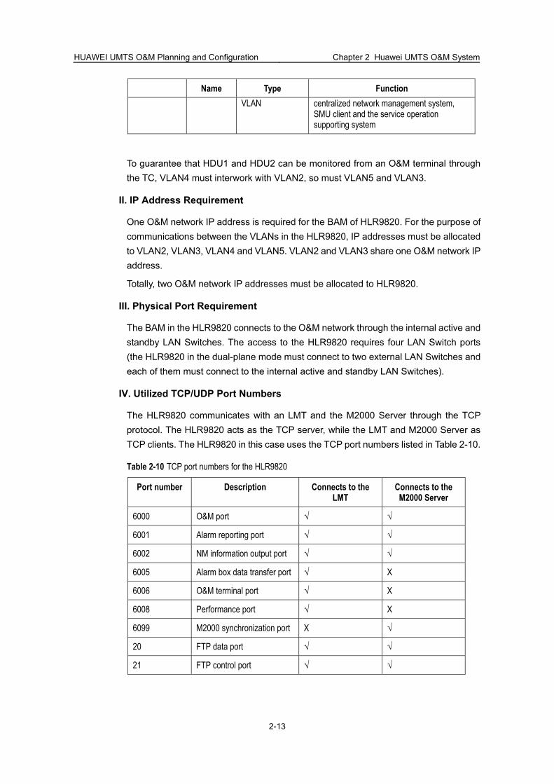
One O&M network IP address is required for the BAM of HLR9820. For the purpose of communications between the VLANs in the HLR9820, IP addresses must be allocated to VLAN2, VLAN3, VLAN4 and VLAN5. VLAN2 and VLAN3 share one O&M network IP address.
Totally, two O&M network IP addresses must be allocated to HLR9820.
III. Physical Port Requirement
The BAM in the HLR9820 connects to the O&M network through the internal active and standby LAN Switches. The access to the HLR9820 requires four LAN Switch ports (the HLR9820 in the dual-plane mode must connect to two external LAN Switches and each of them must connect to the internal active and standby LAN Switches).
IV. Utilized TCP/UDP Port Numbers
The HLR9820 communicates with an LMT and the M2000 Server through the TCP protocol. The HLR9820 acts as the TCP server, while the LMT and M2000 Server as TCP clients. The HLR9820 in this case uses the TCP port numbers listed in Table 2-10.
Table 2-10 TCP port numbers for the HLR9820
Port number Description Connects to the LMT
Connects to the M2000 Server
6000 O&M port √ √
6001 Alarm reporting port √ √
6002 NM information output port √ √
6005 Alarm box data transfer port √ X
6006 O&M terminal port √ X
6008 Performance port √ X
6099 M2000 synchronization port X √
20 FTP data port √ √
21 FTP control port √ √

HUAWEI UMTS O&M Planning and Configuration Chapter 2 Huawei UMTS O&M System
2-14
2.5.5 SIWF
I. O&M Access to the SIWF
Generally, the SIWF provides O&M function using the BAM server of the MSOFTX3000. It provides external O&M interfaces through the BAM of the MSOFTX3000.
II. IP Address Requirement
Generally, no IP address needs to be allocated to the SIWF because it does not host independent server.
III. Physical Port Requirement
Generally, no LAN Switch port needs to be allocated to the SIWF because it does not host independent server.
IV. Utilized TCP/UDP Port Numbers
The SIWF communicates with an LMT and the M2000 Server through the TCP protocol. The SIWF acts as the TCP server, while the LMT and M2000 Server as TCP clients. Table 2-11 lists the TCP port numbers used by the SIWF in this case.
Table 2-11 TCP port numbers used by the SIWF
Port number Description Connects to the LMT Connects to the M2000 Server
7000 O&M port √ √
7001 Alarm reporting port √ √
7005 Alarm box data transfer port √ X
7007 Debugging port √ X
7011 O&M terminal port √ X
7017 Remote tracing port √ X
7021 Load port √ X
7099 M2000 synchronization port X √
20 FTP data port √ √
21 FTP control port √ √

HUAWEI UMTS O&M Planning and Configuration Chapter 2 Huawei UMTS O&M System
2-15
2.6 O&M of RAN Devices
2.6.1 Structure of the Radio Access Network
The radio access network (RAN) in the UMTS consists of two types of logical NE: RNC and NodeB. The corresponding Huawei product models are BSC6800 (RNC) and BTS3812/3806/3806A/3802C (NodeB).
In the Huawei RAN system, a BSC6800 directly connects to the centralized network management system but a BTS3812/3806/3806A/3802C does not. The BTS3812/3806/3806A/3802C connects to the centralized network management system through the O&M channel (RNC-NodeB maintenance channel) provided by the BSC6800 connected with it.
This section introduces the O&M access to a BSC6800 or BTS3812/3806/3806A/3802C, the IP address requirement, physical port requirement and the TCP/UDP port numbers used for O&M connections.
This section also introduces the classification, IP address planning and IP route configuration of the subnets on the RNC-NodeB maintenance channel.
2.6.2 BSC6800
I. O&M Access to the BSC6800
The active and standby BAM servers in the BSC6800 provide O&M function and external O&M interfaces. Figure 2-8 shows the O&M access to the BSC6800.
Figure 2-8 O&M access to the BSC6800
II. IP Address Requirement
The active and standby BAM servers provide two Ethernet adapters, which provide external O&M interfaces through adapter teaming technology. Therefore, a BAM server only need be allocated one IP address. The active and standby servers provide external O&M interfaces using virtual IP address technology and require the allocation of a virtual IP address. The O&M system shall access to the BSC6800 through the virtual IP address.
Altogether three IP addresses are required for the BSC6800.

HUAWEI UMTS O&M Planning and Configuration Chapter 2 Huawei UMTS O&M System
2-16
III. Physical Port Requirement
To deploy a BSC6800 in the O&M network, allocate four LAN Switch ports to the BSC6800 as follows:
two for the active BAM server two for the standby BAM server
IV. Utilized TCP/UDP Port Numbers
The BSC6800 communicates with an LMT and the M2000 Server through the TCP protocol. The BSC6800 acts as the TCP server, while the LMT and M2000 Server as TCP clients. Table 2-12 shows the TCP port numbers used by the BSC6800 in this case.
Table 2-12 TCP port numbers used by BSC6800
Port number Description Connects to the LMT Connects to the M2000 Server
6000 O&M port √ √
6001 Alarm reporting port √ √
6002 Performance reporting port √ √
6007 Debugging port √ √
6021 Configuration data reporting port
√ X
6099 Configuration data reporting port
X √
20 FTP data port √ √
21 FTP control port √ √
2.6.3 BTS3812/3806/3806A/3802C
I. O&M Access to the BTS3812/3806/3806A/3802C
BTS3812/3806/3806A/3802C is the NodeB provided by Huawei.
BTS3812/3806/3806A provides local O&M function through the active and standby NMPT boards. BTS3802C provides local O&M access function through the NMCU. BTS3812/3806/3806A/3802C does not connect to the centralized network management directly but communicates with it through the connected BSC6800. BTS3812/3806/3806A/3802C connects to a BSC6800 through an O&M channel in IPoA mode. Figure 2-9 shows the O&M access to the BTS3812/3806/3806A while Figure 2-10 shows that to the BTS3802C.

HUAWEI UMTS O&M Planning and Configuration Chapter 2 Huawei UMTS O&M System
2-17
ActiveNMPT
StandbyNMPT
BTS3812/3806/3806A
NDTI/NAOI BSC6800
IPoAO&M
interfacewith the
LMT
O&Minterfacewith the
centralizednetwork
management system
Figure 2-9 O&M access to the BTS3812/3806/3806A
BTS3802C
NMCU BSC6800
IPoAO&M
interface with thecentralized network
managementsystem
O&Minterfacewith the
LMT
Figure 2-10 O&M access to the BTS3802C
II. IP Address Requirement
The IP address of the BTS3812/3806/3806A/3802C on the IPoA link is that of the NodeB in the O&M system. An IP address must be allocated to each BTS3812/3806/3806A/3802C in the centralized network management system.
In the local maintenance system, an IP address needs to be allocated to the NMCU (in the BTS3802C) or to the active and standby NMPTs (in the BTS3812/3806/3806A).
III. Physical Port Requirement
BTS3812/3806/3806A/3802C does not occupy LAN Switch ports of the O&M system because it does not directly connect to it.
IV. Utilized TCP/UDP Port Numbers
The BTS3812/3806/3806A/3802C communicates with an LMT and the M2000 Server through the TCP protocol. The BTS3812/3806/3806A/3802C acts as the TCP server, while the LMT and M2000 Server as TCP clients. Table 2-13 shows the TCP port numbers used by the BTS3812/3806/3806A/3802C in this case.
Table 2-13 TCP port numbers used for the BTS3812/3806/3806A/3802C
Port number Description Connects to the LMT Connects to the M2000 Server
6000 O&M port √ X
6001 Alarm reporting port √ X
6006 statistics port √ X
6007 See the note below √ √

HUAWEI UMTS O&M Planning and Configuration Chapter 2 Huawei UMTS O&M System
2-18
Note:
Port 6007 in Table 2-13 acts as a debugging port when connecting to an LMT and as a port for reporting alarm, maintenance, debugging data reporting port when connecting to the M2000 Server.
2.6.4 RNC-NodeB Maintenance Channel
I. Overview of the RNC-NodeB Maintenance Channel
As shown in Figure 2-9, a NodeB connects to the local maintenance system through a LAN and to the centralized network management system through the RNC-NodeB maintenance channel in IPoA mode.
The RNC-NodeB maintenance channel can be divided into five subnets. Therefore, the IP addresses of ten nodes need special planning. Figure 2-11 shows the RNC-NodeB maintenance channel.
NodeB WMUXLMT BAMLMT/
M2000
BSC6800
IP1IP2
WMPU
IP3IP4IP5IP6IP7IP8IP9IP10
Subnetwork ASubnetwork BSubnetwork CSubnetwork DSubnetwork E
Figure 2-11 RNC-NodeB maintenance channel
For the subnets on the RNC-NodeB maintenance channel, see the next subsection “II. Subnets on the RNC-NodeB Maintenance Channel”.
For the IP addresses of the nodes on the maintenance channel, see “III. IP Addresses of the Nodes on the RNC-NodeB Maintenance Channel”.
For the IP routes of the subnets on the maintenance channel, see “IV. IP Routes for the Subnets on the RNC-NodeB Maintenance Channel”.
II. Subnets on the RNC-NodeB Maintenance Channel
As shown in Figure 2-11, the RNC-NodeB maintenance channel are divided into five subnets, as described in Table 2-14.
Table 2-14 Description of the subnets on the RNC-NodeB maintenance channel
Subnet Description Configuration requirement
External network of the BAM
Corresponds to subnet A, connects the BSC6800 BAM and LMT/M2000, and provides external O&M interfaces of RAN
Requires uniform planning according to the O&M network

HUAWEI UMTS O&M Planning and Configuration Chapter 2 Huawei UMTS O&M System
2-19
Subnet Description Configuration requirement
Internal network of the BAM
Corresponds to subnet B, connects the BAM and WMPU in the BSC6800
Requires planning on site
Inter-RNC network
Corresponds to subnet C, connects the WRSS and WRBS subracks in the BSC6800 and provides inter-subrack communications channels. The WMPU in the WRSS subrack connects to the WMUX in the WRBS to form an internal LAN. The IP address segment of the LAN is fixed as 192.1.1.0/24. The IP address of the WMPU in the LAN is 192.1.1.254/24 and that of the WMUX in the LAN is 192.1.1.n (n refers to the number of a WRBS subrack).
Unnecessary to be planned on site
IPoA network Corresponds to subnet D, connects the BSC6800 and NodeB in IPoA mode, and provides maintenance channel for the NodeB. Each WMUX in the WRBS sets up an IPoA connection with the connected NodeB and all the IPoA connections in a WRBS form an independent subnet. Up to 16 subnets of such type can be divided in a BSC6800.
Requires planning on site
local maintenance subnet of NodeB
Corresponds to subnet E, provides local maintenance and reverse maintenance for NodeB. Each NodeB corresponds to a local maintenance subnet.
Requires planning on site
III. IP Addresses of the Nodes on the RNC-NodeB Maintenance Channel
As shown in Figure 2-11, the IP addresses of the ten nodes on the RNC-NodeB maintenance channel require special focus. Table 2-15 shows the descriptions of these IP addresses.
Table 2-15 IP addresses of the nodes on the RNC-NodeB maintenance channel
Number Description Configuration requirement
IP1 IP address of the BSC 6800 LMT, belongs to subnet A together with IP2
Requires planning on site
IP2 IP address of the BAM external network of BSC6800, that is, IP address of the BSC6800 in the O&M network. The M2000 and LMT access to the RAN through this IP address. This IP address is in subnet A together with IP1.
Requires planning on site
IP3 IP address of the internal network of BAM in BSC6800, in subnet B together with IP4
Requires planning on site
IP4 IP address of the BAM connected to the WMPU in the BSC6800, in subnet B together with IP3
Requires planning on site
IP5 IP address of the inter-subrack IPoA interface on the WMPU in the BSC6800, fixed as 192.1.1.254/24 and located in subnet C together with IP6
Unnecessary to be planned or configured on site

HUAWEI UMTS O&M Planning and Configuration Chapter 2 Huawei UMTS O&M System
2-20
Number Description Configuration requirement
IP6 IP address of the inter-subrack IPoA interface on the WMUX in the BSC6800, fixed as 192.1.1.n (n refers to the number of the WRBS) and located in subnet C together with IP5
Unnecessary to be planned or configured on site
IP7 IP address of the IPoA interface between the WMUX in BSC6800 and NodeB, located in subnet D together with IP8
Requires planning on site
IP8 IP address of the IPoA interface at the NodeB connected to the WMUX in the BSC6800, located in subnet D together with IP7
Requires planning on site
IP9 IP address for local maintenance of the NodeB, used for the LMT to be accessed to the RAN, located in subnet E together with IP10
Requires planning on site
IP10 IP address of the LMT in the local maintenance system for NodeB, located in subnet E together with IP9
Requires planning on site
IV. IP Routes for the Subnets on the RNC-NodeB Maintenance Channel
Figure 2-16 lists the routes to be configured for the subnets in Figure 2-11.
Table 2-16 IP routes on the RNC-NodeB maintenance channel
Node Route Configuration requirement
BAM Route to subnet D, with the next hop of IP4, forward NodeB maintenance channel
Requires planning on site
WMPU Route to subnet D, with the next hop of IP6, forward NodeB maintenance channel
Requires planning on site
Route to subnet A, with the next hop of IP9, reverse NodeB maintenance channel
Requires planning on siteNodeB LMT
Route to subnet D, with the next hop of IP9, reverse maintenance channel
Requires planning on site
Route to subnet A, with the next hop of IP7, reverse maintenance channel
Automatically configured by the NodeB system
NodeB
Route to subnet D, with the next hop of is IP7, reverse maintenance channel
Automatically configured by the NodeB system
WMUX Route to subnet A, with the next hop of IP5, reverse maintenance channel
Requires planning on site
WMPU Route to subnet A, with the next hop of IP3, reverse maintenance channel
Requires planning on site

HUAWEI UMTS O&M Planning and Configuration Chapter 2 Huawei UMTS O&M System
2-21
2.7 Huawei UMTS O&M Network
2.7.1 Logical Topology of Huawei UMTS O&M Network
The Huawei UMTS O&M system operates on the TCP/IP protocol stack. Figure 2-12 shows the logical topology of this O&M system.
CN-PS
IWFLMT
Local maintenancesystem
MGW LMT
Local maintenancesystem
HLRLMT
Local maintenancesystem
CGLMT
Local maintenance system
RNCLMT
Local maintenance system
GGSNLMT
Local maintenance system
SGSN LMT
Local maintenance system
NodeBLMT
Local maintenance system
MSCServerLMT
Local maintenancesystem
CN-CS
RAN Centralized networkmanagement system
LMTLMTLMT
M2000M2000M2000Client
M2000Server
LANSwitch
Router
Firewall
IP bearingnetwork
Figure 2-12 Logical topology of the Huawei O&M network
The UMTS O&M network consists of M2000 and one or more of the CN-PS, CN-CS and RAN subnets according to the scope of the managed network elements.
2.7.2 Centralized Network Management System
The centralized network management system is the O&M platform of the UMTS under normal situations. It provides NE topology management, centralized configuration, and centralized alarm, performance, software and security management functions.
The centralized network management system sets up an IP connection to a managed NE through the IP bearing network. You can operate and maintenance various NEs through the centralized network management system and an LMT. The centralized network management system consists of the following:
iManager M2000, including M2000 Server and M2000 Client NE LMTs

HUAWEI UMTS O&M Planning and Configuration Chapter 2 Huawei UMTS O&M System
2-22
IP bearing network, generally including the lower-layer transport network and IP networking devices, such as routers, firewalls and LAN Switches
An IP bearing network provides IP bearers for the O&M data such as alarm, configuration and performance data between NEs and the centralized network management system. The specific IP bearer mode can be selected according to the actual situations (See “2.8 IP Bearer Modes for O&M Networks”).
2.7.3 Local Maintenance System
Local maintenance indicates that you can operate and maintain an NE at the place the NE is located. Local maintenance functions generally include local alarm query, NE configuration, signaling tracing and so on. Local maintenance is used for troubleshooting during initial software installation and system commissioning of a certain device and even under special occasions.
A local maintenance system consists of the NE device and the corresponding LMT, which are connected through a LAN.
A local maintenance system can be configured according to actual requirements.
2.8 IP Bearer Modes for O&M Networks
2.8.1 Introduction to IP Bearer Modes
Huawei UMTS O&M system has no restriction to the IP bearing networks, as long as it can support TCP/IP protocol and ensure the required O&M bandwidth. For the Huawei UMTS O&M bandwidth requirements, see “2.8.2 Bandwidth Requirement”.
The common networks over IP bearers in an O&M system are as follows:
LAN
In this networking mode, the IP connections in an O&M system are borne on an Ethernet LAN. For details, see “2.8.3 LAN”.
WAN on E1/T1
In this networking mode, the IP connections in an O&M system are borne on E1/T1 links. The E1/T1 bearing includes complete E1/T1 bearing and partial E1/T1 bearing. For details, see “2.8.4 WAN over E1/T1”.
WAN on DDN/X.25
This mode indicates that the IP connections in an O&M system are borne on a DDN or an X.25 network. For details, see “2.8.5 WAN over DDN/X.25 Network”.
2.8.2 Bandwidth Requirement
The O&M bandwidth requirement depends on the type and number of devices in the UMTS system. Table 2-17 lists the bandwidths required for the O&M channels between the M2000 Server and other NEs.

HUAWEI UMTS O&M Planning and Configuration Chapter 2 Huawei UMTS O&M System
2-23
Table 2-17 Bandwidth requirements for the O&M channels between M2000 Server and other NEs
NE Bandwidth requirement (kbit/s)
MSC server+HLR 128
MGW 64
SGSN+CG 128
GGSN 64
RNC 128
100 NodeBs 128
M2000 Client 128
2.8.3 LAN
The networking in the LAN mode indicates that all network devices are connected in an Ethernet LAN and that all O&M data is transmitted in the LAN.
A LAN is suitable for the network where the NEs are located in one place.
Figure 2-13 shows an O&M system in the LAN connection mode.
M2000Server
NE1 NE2 NE n
NodeBLMT
NodeBLMTLMT
NodeBLMT
NodeBLMT
M2000Client
Figure 2-13 O&M system in the LAN connection mode
Note:
Table 2-13 shows only a logical networking mode. IP network devices, such as routers and firewalls, may be required in actual networking.

HUAWEI UMTS O&M Planning and Configuration Chapter 2 Huawei UMTS O&M System
2-24
2.8.4 WAN over E1/T1
I. Overview of E1/T1 Bearers
A WAN over E1/T1 indicates that NEs and network management devices are connected in a WAN and that the IP links in the WAN are borne on E1/T1 transport links.
E1/T1 bearers include partial E1/T1 bearing and entire E1/T1 bearing. The former bearing mode indicates that some timeslots on an E1/T1 link bear a WAN. The latter indicates that all the timeslots on an E1/T1 link bear a WAN.
When an IP bearing network adopts the entire E1/T1 bearing, you need to configure routers and LAN Switches for the IP bearing network. When the partial E1/T1 bearing is adopted, you also need to configure digital timeslot cross-connecting devices (for example, Mercury 3600) for the IP bearing network.
The E1/T1 bearing mode is generally used to connect the NEs unable to be connected in a LAN in case of available E1/T1 resources. Compared to the partial E1/T1 bearing mode, the entire E1/T1 bearing does not involve timeslot extraction or cross-connection. It can transmit network management data using the 2 M or 1.5 M bandwidth of an entire E1/T1 link. It is applicable to the networking in case of abundant transport resources and heavy traffic.
II. WAN over Entire E1/T1
Figure 2-14 shows the networking of WAN over entire E1/T1. The routers in this diagram must be able to provide E1/T1 ports.
Figure 2-14 WAN over entire E1/T1

HUAWEI UMTS O&M Planning and Configuration Chapter 2 Huawei UMTS O&M System
2-25
III. WAN over Partial E1/T1
Figure 2-15 shows a networking of WAN over partial E1/T1. Compared with the networking in Figure 2-14, the WAN over partial E1/T1 involves digital timeslot cross-connecting devices (shadow patterns in Figure 2-15).
Router
Router
Router
M2000
LMTLAN
Digital timeslotcross-connecting
device E1/T1transportnetwork
IP bearing network
NE1LMT
NE2LMT
Local maintenancesystem
Local maintenancesystem
Digital timeslotcross-connecting
device
Digital timeslotcross-connecting
device
Figure 2-15 WAN over partial E1/T1
Note:
E1/T1 transport links are widely used to transport signaling and data in the present mobile telecommunications networks. These E1/T1 transport links form an E1/T1 transport network. An O&M system that adopts E1/T1 bearers for networking can make good use of the idle E1/T1 links in the E1/T1 transport network, raise the network utilization and save the investment from users. Therefore, WAN over E1/T1 is widely used networking mode.
2.8.5 WAN over DDN/X.25 Network
WAN over DDN/X.25 network indicates that the NEs and network management devices are connected in a WAN and that the IP links of the WAN are borne on a conventional digital communications network (DDN/X.25).
An IP bearing network that adopts WAN over DDN/X.25 needs to be configured routers, LAN Switches and even firewalls.
WAN over DDN/X.25 mode can provide reliable communications and stable transmission quality but it is expensive. It is generally used to connect the NEs that cannot be connected into a LAN when there is no available E1/T1 resource or the carrier has its own DDN/X.25 private network.

HUAWEI UMTS O&M Planning and Configuration Chapter 2 Huawei UMTS O&M System
2-26
Figure 2-16 shows a WAN over DDN/X.25. The firewalls and routers need be configured according to the actual networking mode.
Figure 2-16 WAN over DDN/X.25

HUAWEI UMTS O&M Planning and Configuration Chapter 3
Huawei Security Solutions to UMTS O&M Network
3-1
Chapter 3 Huawei Security Solutions to UMTS O&M Network
3.1 Overview of the Security Solutions Network security is an essential role in UMTS O&M network. It is also a big issue attracting much attention from carriers. This chapter introduces the security requirements for the O&M network and solutions to Huawei O&M network security.
3.2 Security Requirements for the O&M Network
3.2.1 Overview of the Security Requirements
An UMTS O&M network adopting the IP network technology faces serious security risks. As the O&M platform of a telecommunications network, the O&M network must comply with the following security requirements:
guaranteeing normal operation of the O&M network guaranteeing O&M data security
3.2.2 Guaranteeing Normal Operation of the O&M Network
I. Typical Security Attacks
The present attacks to the normal operation of the O&M network include:
illegal intrusion to the network virus attacks failure in network devices
II. Security Protection Solutions
The commonly used measures to keep the O&M network in normal operation and from attacks in actual networking include:
Deploy firewalls
Firewalls can be deployed in the O&M network to prevent it from illegal intrusion.
Install antivirus programs in the computer
Antivirus programs can be installed in the computer that runs the O&M system to prevent or reduce the impact from the virus attacks.
Configure backup operation channels
To increase the security in the O&M network, you can set a backup O&M channel to ensure normal operation of the O&M system when the active channel is out of service.

HUAWEI UMTS O&M Planning and Configuration Chapter 3
Huawei Security Solutions to UMTS O&M Network
3-2
3.2.3 Guaranteeing O&M Data Security
I. Typical Security Attacks
The present attacks to the security in the O&M data include:
Sniffing O&M data Illegal manipulation of O&M data
II. Protection Solutions
The commonly used measures to ensure the security in the O&M data in actual networking include:
Rational networking
Rational networking indicates that the IP bearing networks are connected using private networks and divided into VLANs properly.
Data encryption
Ciphering and encryption of the O&M date can keep the data from illegal access and utilization.
Data check
Checks of the received O&M data can detect whether it is illegally manipulated.
3.3 Security Solutions to Huawei O&M Network
3.3.1 Features of the Security Solutions
The features of Huawei’s solutions to the UMTS O&M network security include:
Encryption of data
The O&M data in the Huawei UMTS O&M system is encrypted during the transmission and transmitted through internal protocols. This can ensure data security.
Provision of dual-plane networking for maintenance
All the UMTS devices of Huawei can provide dual-plane networking functions. The dual-plane O&M network can greatly increase the security and stability of the O&M network and decrease probable disruption of the O&M network due to maintenance channel failure.
Uniform planning of IP subnets and security zones
The rational planning and construction of the O&M network, and uniform planning IP subnet and security zones in the network can reduce:
- network congestion and storms,
- impact on the network,
- and spreading of viruses on the O&M network.

HUAWEI UMTS O&M Planning and Configuration Chapter 3
Huawei Security Solutions to UMTS O&M Network
3-3
Proper planning of backup channels can reduce or even avoid interruption of the O&M network.
The deployed firewalls form a security zone for the O&M network devices. They can control the data streams and protect against external attacks.
Virus protection settings
According to the features of the servers and O&M terminals in the O&M network, different virus protection settings are used:
For a Windows 2000 server-based server, the SetWin2000 and SysPatron are installed to protect against attacks.
For a UNIX-based server, the server immune measures developed by Huawei are adopted.
An O&M terminal is installed antivirus software.
Strict security regulations
To ensure security in the O&M network, the personnel engaged in O&M are prohibited to:
- install maintenance-unrelated software in the server or client of the O&M system,
- share files or copy files to the server or client of the O&M system
- use the server or client for purposes other than maintenance.
Strict account and authority management
Huawei’s UMTS devices provide operator management function. You can use this function to configure operator accounts and authority allocation policy, thus achieving strict management of the user names and passwords in the O&M network.
The security mechanisms and authority management function in the O&M network are developed according to the actual network and requirements from carriers.
This chapter does not introduce how to work out these security protection measures but describes the firewall deployment and configuration and virus protection settings.
3.3.2 Introduction to Security Zone
The concept of security zone comes from firewall products. A security zone corresponds to a logical region or area. The information assets in one security zone have the same or similar security properties, for example, security levels, threats, weekness and risks.
The systems in one security zone trust each other. Each security zone contains the networks connected to one or more interfaces of a firewall device. When network data flows between different security zones, the firewall between the security zones shall check whether the data complies with the security mechanism of the firewall itself. When network data flows different interfaces in one security zone, the firewall between the interfaces does not check the data according to the security mechanism.

HUAWEI UMTS O&M Planning and Configuration Chapter 3
Huawei Security Solutions to UMTS O&M Network
3-4
Security zones are divided in the following principles:
divide the network environments facing similar security threats into one security zone
divide the service networks at the same security level to into one security zone divide the service networks requiring the same security requirements and
providing the same protection measures into one security zone
A security zone can be divided into several sub-zones and each sub-zone can be divided further. Security zones serve as the basis for security in services. They can control security events and protect against security risks.
3.3.3 Security Zone Classification Principles
As shown in Figure 2-12, an UMTS O&M network consists of one centralized network management system and three subnets: CN-PS, CN-CS and RAN. Each of the subnets includes a local maintenance system.
Each local maintenance system of an UMTS device can act as an independent security zone. It connects to the centralized network management system through firewall devices. If the networking condition permits, security zones can form as follows:
The local maintenance systems of all the CN-PS devices form a security zone. The local maintenance systems of all the CN-CS devices form a security zone. The local maintenance systems in each RAN form a security zone.
Generally, the O&M terminals (including the LMT and M2000 Client) in the centralized network management system form a security zone and the M2000 Server acts as another security zone.
3.3.4 Firewall Deployment and Configuration
I. Overview
A firewall mainly provides flow filtering and protects against network attacks. Firewall devices are required to be deployed between different security zones.
II. Flow Filtering Configuration
Flow filtering configuration indicates that you can set the security check mechanism of a firewall to ensure the security in the O&M network. A firewall that supports flow filtering allows the flow of data complying with the preset conditions and filters the network data not in accordance with the conditions.
In an O&M network, the device types and quantity, and the type of data streams between the device nodes are limited and clear. This makes it possible to filter illegal data streams through firewall settings.
For the types of data streams between different nodes, see “Chapter 2 Huawei UMTS O&M System”.

HUAWEI UMTS O&M Planning and Configuration Chapter 3
Huawei Security Solutions to UMTS O&M Network
3-5
The legal data streams in an O&M network include:
Data streams between the LMT and device Data streams between the M2000 Server and UMTS devices Data streams between the M2000 Client and M2000 Server Data streams between the M2000 Server and NMS Antivirus code updating data streams
III. Attack Protection Functions
To configure a firewall, be sure to enable the following attack functions of it:
IP spoofing protection function Land attack protection function Smurfing protection function Fraggle attack protection function WinNuke attack protection function SYN Flood protection function ICMP Flood protection function UDP Flood protection function ICMP redirected packet control function ICMP unreachable packet control function IP address scan protection function Port scan protection function Control of IP packets with source route option Control of IP packets with routing record option Tracert packet control function Ping of Death attack protection function Teardrop protection function TCP packet validity detection function IP packet fragmenting detection function Control of oversize ICMP packets
3.3.5 Virus Protection Settings
Note:
Huawei recommends the following virus protection solutions as network security solutions. The carrier can also adopt other virus protection solutions according to the actual requirements and through negotiations with Huawei.

HUAWEI UMTS O&M Planning and Configuration Chapter 3
Huawei Security Solutions to UMTS O&M Network
3-6
I. Virus Protection Settings for Windows 2000 Server-based Servers
The Windows 2000 Server-based servers, for example, the BAM servers of MSOFTX3000 need to adopt SetWin2000 and SysPatron to guarantee the server security.
Note:
For the description of SetWin2000, see “6.3 SetWin2000". For the description of SysPatron, see “6.4 SysPatron”.
The preceding servers to adopt the SetWin2000 and SysPatron software include:
BAM server in MSOFTX3000 Emergency workstation in MSOFTX3000 Active and standby iGWB servers in MSOFTX3000 BAM server in HLR9820 BAM server in the SIWF Active and standby BAM servers in BSC6800 Active and standby servers (WIN2000 Server-based) in CG9812
II. Virus Protection Settings for UNIX Server-based Servers
The UNIX-based servers need to adopt the server immune solution developed by Huawei to ensure security. These servers include:
Active and standby servers of M2000 Active and standby servers (UNIX-based) in CG9812
III. Virus Protection Settings for O&M Terminals
The O&M terminals in the Huawei UMTS O&M network adopt antivirus software (developed by Trend) to protect against virus invasion.
Note:
The antivirus software series of Trend ® is developed by Trend Micro (China) Incorporated. For the details about the software, see relevant technical documentation from Trend.
The company name, trademarks, manual names and so on are all reserved for Trend.
The O&M terminals to adopt the antivirus software include:
LMTs of the devices in the O&M network M2000 Client

HUAWEI UMTS O&M Planning and Configuration Chapter 3
Huawei Security Solutions to UMTS O&M Network
3-7
3.3.6 Antivirus Software Deployment Schemes
To deployment antivirus software for the O&M system, select different deployment schemes according to the actual networking modes.
I. Antivirus Software from Trend
Table 3-1 lists the descriptions of the antivirus software from Trend.
Table 3-1 Description of the antivirus software from Trend
Software Function
TMCM Provides centralized virus monitor and killing for the entire O&M network, creates scheduled scans for remote and regular detection, and provides log management and updating management functions
ServerProtect Specially used to protect servers against virus invasion and applicable to the protection of such operating systems as Windows NT Server, Windows 2000 Server. The ServerProtect is divided into two parts: server used for service management and client software used for service implementation.
OfficeScan Used to protect desktop workstations against virus invasion and applicable to the protection of such operating systems as Windows 9x, Windows 2000 Professional and Windows XP. This OfficeScan software is also divided into two parts, the same as ServerProtect.
Note:
For the detailed descriptions of TMCM, ServerProtect and OfficeScan software, see the relevant technical documentation from Trend.
II. TMCM plus OfficeScan
The scheme of TMCM plus OfficeScan is used for virus protection of the entire O&M network or a LAN that contains multiple O&M terminals. Figure 3-1 shows the networking using the scheme of TMCM plus OfficeScan.

HUAWEI UMTS O&M Planning and Configuration Chapter 3
Huawei Security Solutions to UMTS O&M Network
3-8
TMCM
OfficeScan server 1 OfficeScan server 2
OfficeScan client
Trend updatingserver
Centralized networkmanagement system
LAN 2LAN 1
Connected through Internet
OfficeScan clientOfficeScan clientOfficeScan client
Figure 3-1 Networking using the scheme of TMCM plus OfficeScan
As shown in Figure 3-1, the TMCM software is installed on a standalone computer (generally in the centralized network management system), you can connect TMCM to the Internet to obtain the latest virus codes and scan engine. The OfficeScan server must be installed on a standalone computer to provide management functions. The OfficeScan client can run an O&M terminal to provide virus protection.
The computer installed TMCM and OfficaScan server is protected from virus infection through the ServerProtect software. Therefore, the following installation is necessary:
Install the ServerProtect client software on the computer installed OfficaScan server.
Install the software of ServerProtect client servers on the computer already installed the TMCM software.
III. OfficeScan
If there only several O&M terminals in an O&M network, you can deploy only OfficeScan. Figure 3-2 shows a networking using the OfficeScan scheme.

HUAWEI UMTS O&M Planning and Configuration Chapter 3
Huawei Security Solutions to UMTS O&M Network
3-9
OfficeScan server
OfficeScan client 1 OfficeScan client 2 OfficeScan client n
Trend updatingserver
Connected through Internet
Figure 3-2 Networking using the OfficeScan scheme
As shown in Figure 3-2, Install the OfficeScan server on a standalone computer for management purposes and install the OfficeScan client on an O&M terminal to protect the terminal against virus attacks. You can connect the OfficeScan server (computer) to the Trend updating server through the Internet to obtain the latest virus codes and scan engines.
Because the computer installed with OfficaScan server software is protected from virus invasion through the ServerProtect software, you need to install the software of ServerProtect client and server on this computer.
3.3.7 Antivirus Software Updates
To protect against computer viruses effectively, the virus codes and scan engine of the antivirus software must be updated in time. Trend provides updated server on the Internet. You can obtain the latest virus codes and scan engine from the Internet in time.
The antivirus software can be updated in two modes:
Manual update
Manual updating indicates that you can log in to the Internet from an external computer of the O&M network and download the updated antivirus software package to a secure (no virus) storage medium such as floppy disk. Then you can load the software package to the TMCM or OfficaScan server.
Automatic update
After dividing the O&M network into security zones and deploying firewall devices, you can deploy the TMCM or OfficaScan server on the Internet for real-time updating of the firewall software. When the TMCM or OfficaScan server connects to the OfficaScan client through the firewall devices, the client can be updated automatically.

HUAWEI UMTS O&M Planning and Configuration Chapter 4 O&M Network Planning
4-1
Chapter 4 O&M Network Planning
4.1 Overview of O&M Network Planning The O&M network in an UMTS system plays an important role. It must be well planned according to the network features and O&M requirements. This chapter introduces:
Basic principles for the O&M network planning Flow of the O&M network planning
4.2 Basic Principles of O&M Network Planning To plan the UMTS O&M network, follow the principles below:
Security principle
When planning the O&M network, guarantee the security in the O&M network and the UMTS system and keep the network in normal operation.
Cost-saving principle
Despite the provision of abundant O&M functions and guarantee of the network security, save the investment from the carrier as possible as you can during the planning.
Expandability principle
To enable the O&M network to support smooth updating, guarantee the expandability of the O&M network so that it only requires slight changes to comply with the O&M demands after the capacity expansion of the UMTS system.
4.2.1 Security Principles
When planning the O&M network, consider the following factors regarding security:
Isolate the O&M network from a service network
Generally, an UMTS system comprises an O&M network and a service network. The two networks need be physically isolated. If it is different to isolate them, plan them in different VLANs at least.
Deploy firewalls and uniformly plan security zones and IP subnets
To protect the O&M network from external attacks and to achieve flow control, deploy firewalls to form security zones for the network devices and uniformly plan IP subnets and IP routes.
Rationally plan internal subnets
To reduce network congestion and storms, rationally plan the hierarchy of the subnets and VLAN configuration of the internal LAN Switches in the O&M network.
Consider backup mechanism

HUAWEI UMTS O&M Planning and Configuration Chapter 4 O&M Network Planning
4-2
The O&M backup mechanism includes O&M system backup and O&M channel backup. The O&M channel backup involves route backup and network backup.
The Huawei UMTS system equipment supports dual-plane O&M function.
Note:
Huawei security solutions to UMTS O&M networks are designed according to the features and security requirements of the UMTS O&M network. The purpose of the solutions is to provide reference for the carrier during O&M network planning. For the details about the solutions, see “Chapter 3 Huawei Security Solutions to UMTS O&M Network”.
4.2.2 Cost-Saving Principle
When planning the O&M network, consider the following factors to save the cost:
Guarantee user investment
To save user investment, adopt the existing equipment of the carrier as much as possible to plan the networking mode or use the cost-saving networking mode if it can satisfy the O&M requirements.
Reduce O&M work
To save the investment of carrier during network planning, make the routine O&M of the carrier easy-to-use and reduce unnecessary O&M procedures.
4.2.3 Expandability Principle
The expandability of the O&M network indicates that the O&M network in an UMTS system only requires slight changes to comply with the O&M requirements after the capacity expansion of the UMTS system.
The capacity expansion of an UMTS system may involve:
New IP addresses New O&M bandwidth New IP bearing network
Therefore, consider the following factors for the probable capacity expansion in the future during O&M network planning:
Consider the requirement of new IP addresses during IP address planning Consider the requirement of new bandwidth during IP bearer mode planning Consider the future network topology and reserve some ports on the LAN
Switches, routers and firewalls during the planning and selection of IP networking devices

HUAWEI UMTS O&M Planning and Configuration Chapter 4 O&M Network Planning
4-3
4.3 Flow of O&M Network Planning Figure 4-1 shows the O&M network planning flow.
Start
Understand the UMTS O&Mnetwork
Determine IP bearing modes
Determine the operation andmaintenance network structure
Determine the node IPaddresses
Determine IP routes
End
Determine firewall configuratio
Figure 4-1 O&M network planning procedure
4.3.1 Understanding UMTS Network Information
To well plan an UMTS network, first know the following knowledge:
Type and quantity of the UMTS network devices Distribution of the UMTS NE devices Capacity of the UMTS network Capacity expansion planning for the UMTS network Possible bandwidth of O&M data Information about the existing transport network of the carrier and planning of the
transport network
4.3.2 Determining IP Bearing Networking
According to the UMTS network layout, transport network situations, maintenance data bandwidth requirement and UMTS network expansion planning, determine which one

HUAWEI UMTS O&M Planning and Configuration Chapter 4 O&M Network Planning
4-4
of (LAN, WAN over E1/T1 and WAN over DDN/X.25) is to be selected as the IP bearer networking mode through negotiation with the carrier.
To determine the IP bearing networking, consider the factors below:
Existing transport network information of the carrier and planning of the new network
Guarantee the bandwidth requirement for the UMTS O&M network Guarantee the O&M network can be expanded together with the UMTS system Reduce the cost in the IP bearing network under the precondition that the O&M
network keeps working stably.
Note:
For the commonly used IP bearer modes and bandwidth requirements of the UMTS devices, see “2.8 IP Bearer Modes for O&M Networks”.
4.3.3 Determining O&M Network Structure
To determine the structure of the O&M network perform as follows:
Classify VLANs
Generally, classify the CN-PS, CN-CS or each RAN system to a unique VLAN.
Classify security zones
Each VLAN serves as a security zone. Different VLANs cannot access directly generally. In addition, the O&M terminals in the centralized network management system can be divided according to the maintained objects, that is:
- divide the M2000 Client and LMTs used to maintain the CN-PS devices into a security zone;
- divide the M2000 Client and LMTs used to maintain the CN-CS devices into a security zone;
- divide the M2000 Client and LMTs used to maintain the RAN network devices into a security zone.
Rationally deploy O&M terminals
An O&M terminal consists of LMT and M2000 Client.
For the CN-PS or CN-CS devices, the O&M terminals are generally deployed together with the centralized network management system and no M2000 Client needs to be deployed in the local maintenance system.
For the RAN system, an RNC and the centralized network management system may be deployed in different areas. To facilitate the local maintenance personnel of the RNC to monitor the operations of the NEs in the entire system (including the RAN system,

HUAWEI UMTS O&M Planning and Configuration Chapter 4 O&M Network Planning
4-5
CN-PS system and CN-CS system), you need to deploy one or two M2000 Clients in the local maintenance system of the RNC.
Divide network layers
When the O&M network is complicated, divide it into several layers and make clear the access layer and convergent layer.
Determine virus protection measures
This determination of virus protection measures includes:
- select antivirus software
- select antivirus software deployment
- select antivirus software updating.
Determine IP networking devices and allocate ports
After determining the network structure, select the IP networking devices (including LAN Switches, routers and firewalls) and decide how to allocate the ports on these devices.
4.3.4 Determining IP Addresses for Nodes
The determination of IP addresses for nodes depends on the O&M network structure and the number of IP addresses required for every node.
Existing network IP
When the O&M network acts as part of the existing network (DDN/X.25), the planning of the IP addresses for the O&M network must be compatible with that of the IP addresses for the existing network. In addition, the IP address resources in the existing network are relevantly insufficient, especially, when the network needs to seize the Internet IP addresses. This requires rational planning of the quantity of IP addresses to be used in the O&M network to reduce waste of the IP address resources for the existing network.
In this case, you can properly divide some subnets in the O&M network into according to the classification of VLANS to raise the security in the entire O&M network.
Private network IP
When the O&M network is a LAN or independent private network, there are abundant IP address resources. To raise the security in the O&M network, you can plan more subnets and divide a VLAN to maintain every O&M network device.
During IP address planning in this case, the Class C IP address segment (192.168.0.0–192.168.255.255) for private networks is recommended.
RNC-NodeB maintenance channel IP
The IP addresses on the RNC-NodeB maintenance channel are independent of the connection mode of the O&M network and of the subnet they are located. Therefore,

HUAWEI UMTS O&M Planning and Configuration Chapter 4 O&M Network Planning
4-6
the IP addresses on the RNC-NodeB maintenance are recommended to value in the private network IP address segments.
4.3.5 Determining IP Routes
The determination of IP routes in the O&M network depends on the IP address planning and O&M requirements of the network devices
4.3.6 Determining Firewall Configuration
When there are firewall devices deployed in the O&M network, determine the flow filter configuration of the firewall according to the O&M network structure, O&M requirement of network devices, security zone planning and security mechanism.
For the requirements of flow filter configuration and network attack protection functions of a firewall, see "3.3.4 Firewall Deployment and Configuration“.

HUAWEI UMTS O&M Planning and Configuration Chapter 5 O&M Network Examples
5-1
Chapter 5 O&M Network Examples
5.1 About This Chapter This chapter illustrates typical connections of an UMTS O&M network, including:
UMTS O&M network connected into a LAN UMTS O&M network connected into a WAN Connection of RNC-NodeB maintenance channel subnets
5.2 UMTS O&M Network Connected into a LAN
5.2.1 Overview of the Connection
This section presents an O&M network connected into a LAN. It cover the following contents:
Network configuration condition Planning network structure Planning IP addresses Configuring IP routes
For the planning of the IP addresses and IP routes on the RNC-NodeB maintenance channel, see “5.4 Example of RNC-NodeB Maintenance Channel Networking”.
5.2.2 Network Configuration
I. Network Configuration Condition
Suppose an UMTS system is configured as follows:
One SGSN9810 One GGSN9811 One CG9812 One MSOFTX3000 One UMG8900 One HLR9820 One SIWF, which shares the BAM server of the MSOFTX3000 Two BSC6800s:
- BSC68001 contains four WRBS subracks, each of which connects to 40 NodeBs.
- BSC68002 contains two WRBS subracks, each of which connects to 60 NodeBs.
All the NE devices except NodeB are deployed in the same equipment room with the M2000 Server.

HUAWEI UMTS O&M Planning and Configuration Chapter 5 O&M Network Examples
5-2
II. Existing Networks of Carrier
The carrier has a special office network, operation supporting network and O&M network. In this O&M network, a segment of 64 IP addresses (10.0.1.0/26) is allocated to the UMTS O&M system.
III. Maintenance Requirements from Carrier
The carrier requests centralized maintenance on all the UMTS devices, which needs a set of M2000 system. The carrier also requires that the NE devices can be maintained through the office network.
5.2.3 Planning Network Structure
A LAN is used to carry the O&M network because the UMTS system scale is small and all the NE devices in the system except NodeB are located in an equipment room. Figure 5-1 shows the O&M network connected in a LAN.
Figure 5-1 UMTS O&M network connected in a LAN
As shown in Figure 5-1:
LAN Switch 1 and LAN Swtich 2 connect to the O&M interfaces of every NE. LAN Switch 3 connects to the O&M terminals, LAN Switch 1 and LAN Swtich 2. The O&M terminals deployed in the office network connect to LAN Switch 1 and
LAN Switch 2 through a firewall.
The O&M terminals in Figure 5-1 include LMTs (including the Bill Console of the iGWB in MSOFTX3000) and M2000 Client. MSOFTX3000 provides O&M access for the SIWF. RAN1 comprises BSC68001 and all the NodeBs connected with BSC68001. It connects to the O&M network through the BAM in BSC68001. RAN2 comprises

HUAWEI UMTS O&M Planning and Configuration Chapter 5 O&M Network Examples
5-3
BSC68002 and all the NodeBs connected with BSC68002. It connects to the O&M network through the BAM in BSC68002.
5.2.4 Planning IP Addresses
An IP address segment of 10.0.1.0/26 is reserved for the network in Figure 5-1. Table 5-1 shows the IP address planning in detail.
Table 5-1 IP address planning for an UMTS O&M network connected in a LAN
Device Quantity IP address Configuration
SGSN9810 2 10.0.1.1, 10.0.1.2 One for the active and the other for the standby UOMU
GGSN9811 1 10.0.1.3 One for the active and standby LPU boards
CG9812 3 10.0.1.4, 10.0.1.5, 10.0.1.6
One IP address for each server and one virtual IP address for a server group (active and standby servers)
M2000 Server 3 10.0.1.7, 10.0.1.8, 10.0.1.9
One IP address for each server and one virtual IP address for an external O&M interface group (active and standby interfaces)
iGWB 3 10.0.1.10, 10.0.1.11, 10.0.1.12
One IP address for each server and a virtual IP address for an external O&M interface group
BAM 3 10.0.1.13, 10.0.1.14, 10.0.1.15
One IP address for each server and one virtual IP address for an external O&M interface group
MSOFTX3000
Emergency workstation
1 10.0.1.16 One for the emergency workstation
UMG8900 1 10.0.1.17 One for both the active and standby OMU boards
HLR9820 2 10.0.1.18, 10.0.1.19 One for the BAM and another for the internal VLAN
BSC68001 3 10.0.1.20, 10.0.1.21, 10.0.1.22
One IP address for each server and one virtual IP address for an internal O&M interface group
BSC68002 3 10.0.1.23, 10.0.1.24, 10.0.1.25
One IP address for each server and one virtual IP address for an external O&M interface group
Firewall 1 10.0.1.26 One for the firewall
O&M terminal 5 10.0.1.27–10.0.1.31 One for each O&M terminal
Sum 31 Varies with the number of O&M terminals configured

HUAWEI UMTS O&M Planning and Configuration Chapter 5 O&M Network Examples
5-4
Note:
The IP addresses of the O&M terminals connected through the firewall in Figure 5-1 must be planned according to that of the office network of the carrier. The planning is omitted here.
The SIWF shares the IP addresses of the MSOFTX3000. It is distinguished from the MSOFT3000 by TCP ports.
The other IP addresses are reserved for future network expansion and modification.
5.2.5 Configuring IP Routes
A NodeB does not directly connect to the O&M network. To operate and maintain the NodeB, configure routes on the M2000 Server and on the NodeB LMT according to the IP address planning for the O&M network.
5.3 UMTS O&M Network Connected into a WAN
5.3.1 Overview of the Connection
This section presents an UMTS O&M network connected into a WAN. It covers the following contents:
Network configuration condition Planning network structure Planning IP addresses Configuring IP routes
For the planning of the IP addresses and IP routes on the RNC-NodeB maintenance channel, see “5.4 Example of RNC-NodeB Maintenance Channel Networking”.
5.3.2 Network Configuration
I. Network Configuration Condition
Suppose the devices of an UMTS system are configured in three places, as shown below:
Place X:
One SGSN9810 One GGSN9811 One CG9812 Two BSC6800s, each hosts four WRBS subracks and each subrack connects with
40 NodeBs.
Place Y:
One MSOFTX3000 One UMG8900

HUAWEI UMTS O&M Planning and Configuration Chapter 5 O&M Network Examples
5-5
One HLR9820 One SIWF, which shares the BAM server of the MSOFTX3000 Two BSC6800s, each has a WRBS subrack that connects with 60 NodeBs.
Place Z: There are only one BSC6800, which hosts two WRBS subracks. Each WRBS subrack connects with 40 NodeBs.
II. Existing Networks of Carrier
The carrier has a LAN connected to the networks in the three places and there is private O&M network in each place.
III. Maintenance Requirements from Carrier
The carrier requires the O&M system of CN (including CN-PS and CN-CS) to be separated from that of the RAN. This requires two sets of M000 systems. One set is for the O&M system of the CN. The other set is for the O&M system of the RANs.
The carrier also requires that:
The O&M terminals of the UMTS network are deployed in LANs. The UMTS devices are deployed in private O&M networks (the CN devices in a
private O&M network different from the RAN devices). The LANs and the private O&M networks are connected through firewalls able to
support the flow filter function.
5.3.3 Planning Network Structure
Figure 5-2 shows an O&M network connected into a WAN.

HUAWEI UMTS O&M Planning and Configuration Chapter 5 O&M Network Examples
5-6
RAN Z
M2000Server C
M2000Server R
Firewall for RAN
操作维护
终端O&M
terminal
操作维护
终端O&M
terminal
操作维护
终端O&M
terminal
操作维护
终端O&M
terminal
操作维护
终端O&M
terminal
Place X
Place Y
Place Z
Enterprise IntranetO&M network of CN
O&M network of RAN
Gateway 1
RAN X1
RAN X2
RAN Y1
RAN Y2
Gateway 3Gateway 2
Firewall for CN
SGSN
GGSN
CGGateway 4
MSCServer
HLR
MGW
Gateway 5
Figure 5-2 UMTS O&M network connected into a WAN
As shown in Figure 5-2, M2000 Server and O&M terminals are configured in the enterprise Intranet of the carrier. M2000 Server C provides centralized network management to the CN system and M2000 Server R provides the same functions to the RANs. The M2000 Client software and LMT software of the NE run on each O&M terminal at the same time.
The devices in the CN of the UMTS form a private O&M nework for the CN. The CN-PS devices in place X are converged to gateway 4; the CN-CS devices in place Y are converged to gateway 5. The converged devices connect to the enterprise Intranet through the firewall for CN. The data packets between the firewall and the gateways are routed at layer 2.
The RANs in the UMTS form a private O&M network for RAN. The RAN devices in place X are converged to gateway 1; the RAN devices in place Y are converged to gateway 2; the RAN devices in place Y connect to gateway 3. Then the RAN devices in the three places connect to the enterprise Intranet through the firewall for RAN. The data packets between the firewall and the gateways are routed at layer 2.
For the purpose of centralized network management, the two sets of M2000 system, all the servers and firewalls are deployed in place X.
5.3.4 Allocating IP Addresses to the O&M Devices in the WAN
Table 5-2 lists the IP addresses allocated to the O&M devices in the WAN in Figure 5-2.

HUAWEI UMTS O&M Planning and Configuration Chapter 5 O&M Network Examples
5-7
Table 5-2 IP addresses allocation to the O&M devices in the WAN
Place Device Quantity IP address Allocation
M2000 Server C 3 10.120.0.1, 10.120.0.2, 10.120.0.3
One IP address for each server and a virtual IP address for the external O&M interface
Firewall for CN 1 10.120.0.4 One for the firewall
O&M terminal (used to maintain the CN devices)
5 10.120.0.5–10.120.0.9 One for each terminal
M2000 Server R 3 10.120.0.10, 10.120.0.11, 10.120.0.12
One IP address for each server and a virtual IP address for the external O&M interface
Firewall for RAN 1 10.120.0.13 One
X
O&M terminal (used to maintain the RAN devices)
5 10.120.0.14–10.120.0.18
One for each terminal
O&M terminal (used to maintain the CN devices)
5 10.120.1.5–10.120.1.9 One for each terminalY
O&M terminal (used to maintain the RAN devices)
5 10.120.1.10–10.120.1.14
One for each terminal
Z O&M terminal (used to maintain the RAN devices)
5 10.120.2.10–10.120.2.14
One for each terminal
5.3.5 Planning Addresses for CN
The CN in Figure 5-2 is a private network and the IP addresses in the CN can be planned according to the actual requirements: Here the network segment 10.99.74.0/27 is planned for the CN. The IP addresses 10.99.74.0/28 are allocated to the CN-PS in place X and 10.99.74.16/28 to the CN-CS in place Y. Table 5-3 shows the IP address allocation in detail.
Table 5-3 IP address planning for the CN
Equipment Quantity IP address Configuration
SGSN9810 2 10.99.74.1, 10.99.74.2
One for the active and the other for the standby UOMU board
GGSN9811 1 10.99.74.3 One for both the active and standby

HUAWEI UMTS O&M Planning and Configuration Chapter 5 O&M Network Examples
5-8
Equipment Quantity IP address Configuration LPU boards
CG9812 3 10.99.74.4, 10.99.74.5, 10.99.74.6
One IP address for each server and a virtual IP address for the external O&M interface
Gateway 4 1 10.99.74.14 One for gateway 4 because the data packets between the firewall and the gateway are routed at layer 2
iGWB 3 10.99.74.17, 10.99.74.18, 10.99.74.19
One IP address for each server and a virtual IP address for the external O&M interface
BAM 3 10.99.74.20, 10.99.74.21, 10.99.74.22
One IP address for each server and a virtual IP address for the external O&M interface
MSOFTX3000
Emergency workstation
1 10.99.74.23 One for the emergency workstation
UMG8900 1 10.99.74.24 One for both the active and standby OMU boards
HLR9820 2 10.99.74.25, 10.99.74.26
One IP address for the BAM in HLR9820 and another for the internal VLAN
Gateway 5 1 10.99.74.30 One for gateway 5 because the data packets between the firewall and the gateway are routed at layer 2
Firewall for CN 0 No IP address to the firewall for CN because the data packets between the firewall and the gateways are routed at layer 2
Note:
The SIWF shares the IP addresses of the MSOFTX3000 and is distinguished from the MSOFT3000 according to TCP ports.
The other IP addresses are reserved for future capacity expansion and modification.
5.3.6 Configuring IP Routes for CN
See Table 5-4.

HUAWEI UMTS O&M Planning and Configuration Chapter 5 O&M Network Examples
5-9
Note:
The administrator of the enterprise Intranet determines the IP routes between the nodes in the Intranet. Here the IP addresses in the Intranet are considered to be capable of interworking.
Gateway 4/5 and the firewall for CN adopt layer 2 routing and no IP route is required. For the route planning on the RNC-NodeB maintenance channel, see “5.4 Example of RNC-NodeB
Maintenance Channel Networking”.
Table 5-4 IP route configuration for the CN
Node Configuration
M2000 Server R Route to 10.99.74.0/27. The next hop, that is, IP address of the firewall for CN, is 10.120.0.4.
O&M terminal (used to maintain CN)
Route to 10.99.74.0/27. The next hop, that is, IP address of the firewall for CN, is 10.120.0.4.
SGSN9810 Set the IP address of the gateway (gateway 4) to 10.99.74.14.
GGSN9811 Set the IP address of the gateway (gateway 4) to 10.99.74.14.
CG9812 Set the IP address of the gateway (gateway 4) to 10.99.74.14.
MSOFTX3000 Set the IP address of the gateway (gateway 5) to 10.99.74.30.
UMG8900 Set the IP address of the gateway (gateway 5) to 10.99.74.30.
HLR9820 Set the IP address of the gateway (gateway 5) to 10.99.74.30.
5.3.7 Planning IP Addresses for RAN
The RAN in Figure 5-2 is a private network and the IP addresses of it can be planned according to the actual requirements. Here the IP address segment 10.99.85.0/26 is allocated for the RAN. The IP address segment 10.99.85.0/28 is allocated to the RAN devices in place X, 10.99.85.16/28 to those in place Y and 10.99.85.32/28 to those in place Z. Table 5-5 shows the IP address allocation in detail.
Table 5-5 IP address planning for the RAN
Device Quantity IP address Configuration
BSC6800 X1 3 10.99.85.1, 10.99.85.2, 10.99.85.3
One IP address for each server and a virtual IP address for the external interface
BSC6800 X2 3 10.99.85.4, 10.99.85.5, 10.99.85.6
One IP address for each server and a virtual IP address for the external interface
Gateway 1 1 10.99.85.14 One because the data packets between the gateway and the firewall are routed at layer 2
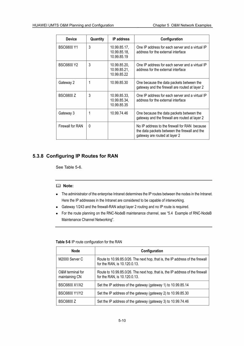
HUAWEI UMTS O&M Planning and Configuration Chapter 5 O&M Network Examples
5-10
Device Quantity IP address Configuration
BSC6800 Y1 3 10.99.85.17, 10.99.85.18, 10.99.85.19
One IP address for each server and a virtual IP address for the external interface
BSC6800 Y2 3 10.99.85.20, 10.99.85.21, 10.99.85.22
One IP address for each server and a virtual IP address for the external interface
Gateway 2 1 10.99.85.30 One because the data packets between the gateway and the firewall are routed at layer 2
BSC6800 Z 3 10.99.85.33, 10.99.85.34, 10.99.85.35
One IP address for each server and a virtual IP address for the external interface
Gateway 3 1 10.99.74.46 One because the data packets between the gateway and the firewall are routed at layer 2
Firewall for RAN 0 No IP address to the firewall for RAN because the data packets between the firewall and the gateway are routed at layer 2
5.3.8 Configuring IP Routes for RAN
See Table 5-6.
Note:
The administrator of the enterprise Intranet determines the IP routes between the nodes in the Intranet. Here the IP addresses in the Intranet are considered to be capable of interworking.
Gateway 1/243 and the firewall-RAN adopt layer 2 routing and no IP route is required. For the route planning on the RNC-NodeB maintenance channel, see “5.4 Example of RNC-NodeB
Maintenance Channel Networking”.
Table 5-6 IP route configuration for the RAN
Node Configuration
M2000 Server C Route to 10.99.85.0/26. The next hop, that is, the IP address of the firewall for the RAN, is 10.120.0.13.
O&M terminal for maintaining CN
Route to 10.99.85.0/26. The next hop, that is, the IP address of the firewall for the RAN, is 10.120.0.13.
BSC6800 X1/X2 Set the IP address of the gateway (gateway 1) to 10.99.85.14
BSC6800 Y1/Y2 Set the IP address of the gateway (gateway 2) to 10.99.85.30
BSC6800 Z Set the IP address of the gateway (gateway 3) to 10.99.74.46

HUAWEI UMTS O&M Planning and Configuration Chapter 5 O&M Network Examples
5-11
5.4 Example of RNC-NodeB Maintenance Channel Networking
5.4.1 Overview of the RNC-NodeB Maintenance Channel Networking
The RNC-NodeB maintenance channel network planning refers to the planning of the IP addresses and IP routes for the subnets on the RNC-NodeB maintenance channel in the RAN. Generally, fixed IP addresses or private network IP addresses are used for the subnets in the RAN, but the addresses of NodeB should abide the IP address planning of O&M networks. For the RNC-NodeB maintenance channel, see “2.6 O&M of RAN Devices“.
This section describes IP address planning and IP route planning for the subnets on the RNC-NodeB maintenance channel.
5.4.2 Network Configuration
In the UMTS network shown in Figure 5-1, the RAN system contains two BSC6800 nodes:
BSC68001 host four WRBS subracks, each of which connects to 40 NodeBs. BSC68002 host two WRBS subracks, each of which connects to 60 NodeBs.
5.4.3 Planning IP Addresses
I. Planning IP Address for O&M Network
See Table 5-1.
II. Planning IP Address for the Internal Network of BSC6800 BAM
The IP address planning for the internal network of the BAM in RAN1 or RAN2 is the same: 192.168.1.0/29. The IP address of the internal Ethernet interface of BAM1 is 192.168.1.1, and that of BAM2 is 192.168.1.2. The virtual IP address of the BAM internal network is 192.168.1.3 and the IP address of the WMPU board is 192.168.1.4.
III. Planning IP Addresses for IPoA Subnets
BSC68001 hosts four WRBS subracks and requires four IPoA subnets. The four subnets are numbered 192.168.2.0/25, 192.168.3.0/25, 192.168.4.0/25 and 192.168.5.0/25. For the IP address planning of the nodes on the subnets, see Table 5-7. Because one BSC6800 can host up to 16 WRBS subracks, 192.168.6.0/25–192.168.17.0/25 is reserved for system capacity.
Table 5-7 IP address planning for the subnets on the NodeB-BSC68001 maintenance channel
Subnet Node IP address
1 WMUX 192.168.2.126

HUAWEI UMTS O&M Planning and Configuration Chapter 5 O&M Network Examples
5-12
Subnet Node IP address
NodeB1 192.168.2.1
…
NodeB40 192.168.2.40
WMUX 192.168.3.126
NodeB1 192.168.3.1
…
2
NodeB40 192.168.3.40
WMUX 192.168.4.126
NodeB1 192.168.4.1
…
3
NodeB40 192.168.4.40
WMUX 192.168.5.126
NodeB1 192.168.5.1
…
4
NodeB40 192.168.5.40
BSC68002 hosts two WRBS subracks and requires two IPoA subnets. The subnets are numbered 192.168.18.0/25 and 192.168.19.0/25. Table 5-8 lists the IP address planning for the nodes on the two subnets. Because one BSC6800 can host up to 16 WRBS subracks, 192.168.20.0/25–192.168.33.0/25 is reserved for system capacity.
Table 5-8 IP address planning for the subnets on the NodeB-BSC68002 maintenance channel
Subnet Node IP route
WMUX 192.168.20.126
NodeB1 192.168.20.1
…
1
NodeB60 192.168.20.60
WMUX 192.168.21.126
NodeB1 192.168.21.1
…
2
NodeB60 192.168.21.60

HUAWEI UMTS O&M Planning and Configuration Chapter 5 O&M Network Examples
5-13
Note:
The IP address of the NodeB in an IPoA subnet is that of the NodeB in the centralized network management system. Therefore, every NodeB IP address must be unique in an UMTS system that hosts multiple BSC6800 NEs.
IV. Planning IP Addresses for Local Maintenance Subnet of NodeB
Each NodeB has a local maintenance subnet and each subnet requires two IP addresses to be allocated. Because the local maintenance subnet of a NodeB is mainly used for special processing, 192.168.255.252/30 is configured for the local maintenance subnets of all NodeBs to simplify IP address planning. The IP address of the local Ethernet port of NodeB is 192.168.255.253 and that of the NodeB LMT is 192.168.255.254.
5.4.4 Configuring IP Routes
Because a NodeB does not directly connect to the O&M network, you need to configure IP routes to maintain the NodeB in both forward and reverse directions according to the planned IP addresses of the RAN and O&M network. Table 5-9 lists the routes that require configuration.
Table 5-9 IP routes to be configured on the RNC-NodeB maintenance channel
Node Configuration
Route to 10.0.1.0/26. The next hop, that is, the virtual IP address of the BAM external network in BSC68001, is 10.0.1.20.
BSC6800 BAM (including the active and standby BAM servers)
Route to 192.168.2.0/25–192.168.17.0/25. The next hop, that is, the IP address of the WMPU in BSC6800, is 192.168.1.4.
Route to 192.168.2.0/25, The next hop, that is, the IP address of WMUX1, is 192.1.1.1.
Route to 192.168.3.0/25. The next hop, that is, IP address of WMUX2, is 192.1.1.2.
Route to 192.168.4.0/25. The next hop, that is, the IP address of WMUX2, is 192.1.1.3.
Route to 192.168.5.0/25. The next hop, that is, the IP address of WMUX2, is 192.1.1.4.
WMPU
Route to 10.0.1.0/26. The next hop, that is, the virtual IP address of the BAM internal network, is 192.168.1.3.
RAN1
WMUX1 Route to 10.0.1.0/26. The next hop, that is, the IP address of the WMPU, is 192.1.1.254.

HUAWEI UMTS O&M Planning and Configuration Chapter 5 O&M Network Examples
5-14
Node Configuration
WMUX2 Route to 10.0.1.0/26. The next hop, that is, the IP address of the WMPU, is 192.1.1.254.
WMUX3 Route to 10.0.1.0/26. The next hop, that is, the IP address of the WMPU, is 192.1.1.254.
WMUX4 Route to 10.0.1.0/26. The next hop, that is, the IP address of the WMPU, is 192.1.1.254.
Route to 10.0.1.0/26. The next hop, that is, the virtual IP address of the BAM external network, is 10.0.1.23.
BSC6800 BAM (including the active and standby BAM servers)
Route to 192.168.18.0/25–192.168.33.0/25. The next hop, that is, the IP address of the WMPU in BSC68002, is 192.168.1.4.
Route to 192.168.18.0/25. The next hop, that is, the IP address of WMUX1, is 192.1.1.1.
Route to 192.168.19.0/25. The next hop, that is, the IP address of WMUX2, is 192.1.1.2.
WMPU
Route to 10.1.0.32/29. The next hop, that is, the virtual IP address of the BAM internal network, is 192.168.1.3.
WMUX1 Route to 10.0.1.0/26. The next hop, that is, the IP address of the WMPU, is 192.1.1.254.
RAN2
WMUX2 Route to 10.0.1.0/26. The next hop, that is, the IP address of the WMPU, is 192.1.1.254.
Local maintenance subnet of NodeB
All the NodeB LMTs Set the local gateway to 192.168.255.253, that is, IP address of the local maintenance Ethernet port of NodeB.

HUAWEI UMTS O&M Planning and Configuration Chapter 6
Background Knowledge Requirements
6-1
Chapter 6 Background Knowledge Requirements
6.1 Overview of the Background Knowledge Requirements This chapter describes some fundamentals required for the UMTS O&M system planning and configuration, including:
IP network related fundamentals SetWin2000 SysPatron
6.2 IP Network Related Fundamentals
6.2.1 IP Address
Note:
Internet protocol (IP) networks include IPv4 network and IPv6 network. The current network is IPv4 network. It is also the network model supported by the Huawei UMTS O&M system. This chapter introduces the coding and subnet masks of the IP addresses in an IPv4 network.
I. Coding of IP Addresses
IP networks use a 32-bit address to identify a host computer and the network to which the host is attached. The 32-bit address is separated into four numerals by dot. Each numeral represents eight bits. A 32-bit address is usually denoted in the format of four decimal numerals, in which each integer corresponds to a byte. This denotion mode is called dotted decimal notation). Table 6-1 shows an IP address denoted in binary and dotted decimal formats.
Table 6-1 Example of an IP address denoted in binary and dotted decimal format
Binary 10001100 10110011 11011100 00000011
Dotted decimal 140. 179. 220. 3
II. Classes of IP Addresses
An IP address consists of two parts: network ID and host ID. The network ID specifies the network to which the host is attached. The host address indicates a specific host in the network. Conventionally, network IDs and host IDs are classified according to the boundaries of the eight bits, that is, the dots.

HUAWEI UMTS O&M Planning and Configuration Chapter 6
Background Knowledge Requirements
6-2
Five classes of IP address formats are defined in the Internet, as shown in Figure 6-1.
1
1
1
1
0
1 0
1 1 0
1 1 1 0
0 Network ID (7) Host ID (24)Class A
Host ID (16)Class B
Network ID (21) Host ID (8)Class C
Multicast group number (28)Class D
ReservedClass E
Network ID (14)
Figure 6-1 Five classes of IP address formats defined in Internet
Table 6-2 lists the value ranges for the five classes of Internet IP address formats in dotted decimal format.
Table 6-2 Value ranges of five classes of Internet IP addresses in dotted decimal format
Class Value range
A 0.0.0.0–127.255.255.255
B 128.0.0.0–191.255.255.255
C 192.0.0.0–223.255.255.255
D 224.0.0.0–239.255.255.255
E 240.0.0.0–247.255.255.255
III. IP Addresses of Private Network
Because the IP address of the host in the Internet must be unique, the IP address of the network to be connected to the Internet must be applied from the specified institute to avoid conflict of IP addresses of different networks.
In addition, some IP addresses among the IP address resources for the Internet are reserved. These reserved IP addresses can be freely used in networks without application. They are called private network IP addresses. Table 6-3 lists the value ranges of the private network IP addresses.
Table 6-3 Value ranges of private network IP addresses
Class Value range
A 10.0.0.0–10.255.255.255
B 172.16.0.0–172.31.255.255
C 192.168.0.0–192.168.255.255

HUAWEI UMTS O&M Planning and Configuration Chapter 6
Background Knowledge Requirements
6-3
IV. Subnet and Subnet Mask
Actually, the host ID of every IP address in Figure 6-1 is further divided into two parts: subnet ID and host ID, as shown in Figure 6-2.
Figure 6-2 Division of an IP address
A subnet mask identifies the expanded network ID obtained through subnet division in Figure 6-2. A subnet mask can define the number of bits used as subnet address in a 32-bit IP address.
The bits of a subnet mask are in one-to-one relation with those of the IP address. If the bits of an IP address are regarded as part of the expanded network ID, set the bits of the subnet mask to 1. On the contrary, if the bits of an IP address are considered as a host ID, set the bits of the subnet mask to zero.
For example, to use the third 8-bit byte in the IP address 130.5.5.25 as subnet ID, set the subnet mask to 255.255.255.0, as shown in Table 6-4.
Table 6-4 Example of the correspondence between the subnet mask and IP address
Network ID Subnet ID Host ID
IP address: 130.5.5.25 10000010 00000101 00000101 00011001
Subnet mask: 255.255.255.0 11111111 11111111 11111111 00000000
In the preceding example, the subnet mask of the IP address 130.5.5.25 is a value of successive 24 1s. The address and subnet mask can be denoted as 130.5.5.25/24.
A subnet can be divided into smaller subnets, which can be further divided if necessary, as shown in Figure 6-3.

HUAWEI UMTS O&M Planning and Configuration Chapter 6
Background Knowledge Requirements
6-4
Figure 6-3 Subdivision of a subnet
6.2.2 IP Routes
An IP network uses IP addresses for communications and data transfer between host computers. It determines the direction of data packets to be transferred according to the destination IP address. The procedure of determining the transfer direction is called IP routing.
For the data packets between the hosts in a subnet, the IP network can obtain the physical address of the hosts through their IP addresses and transfer the data packets. For the data packets between the hosts in different subnets, the IP network must have to route the packets using a special device, that is, a router.
6.2.3 TCP/UDP Port Numbers
In IP networks, data in the application layer is transported through TCP or UDP protocol. In the protocol port numbers are used to identify the application that sends or receives data packets. Port numbers can help the TCP/UDP protocol separate data packets and transfer the corresponding packets to the correct application.
TCP/UDP port number ranges from zero to 65535. This range is divided into three segments:
0–1023, identifies some standard services, for example, FTP, Telnet, SMTP and TFTP
1024–49151, allocated to the registered applications by the Internet Assigned Number Authority (IANA)
49152–65535, serves as private port numbers, flexibly assigned to any application dynamically
TCP/UDP port numbers are usually used together with IP addresses for flow filtering in the security mechanism of a firewall.

HUAWEI UMTS O&M Planning and Configuration Chapter 6
Background Knowledge Requirements
6-5
6.2.4 VLAN
Virtual Local Area Network (VLAN) is a technology that logically divides the devices in a LAN into network segments, achieving virtual workgroups. In 1999, the IEEE released the draft standard of IEEE 802.1Q protocol used to standardize VLAN implementation.
The VLAN technology allows a network administrator to logically divide a physical LAN into different broadcast fields (or virtual LAN, shorted as VLAN). Each VLAN includes a group of computers with the same requirements. Because VLANs are not physically but logically divided, the computers in one VLAN need not be deployed in one physical room, that is, not all these computers belong to a physical LAN.
No broadcast or unicast traffic in one VLAN shall be transferred to the other VLANs. Therefore, VLAN classification can achieve flow control, reduce equipment investment, simplify network management and raise network security.
To achieve network layer functions on a VLAN interface, you need to assign IP address and mask for the VLAN interface.
6.3 SetWin2000
6.3.1 Overview of SetWin2000
Windows 2000 has become the most popular operating system for servers and workstations presently. However, it is easy to be attacked because of its defects and weakness.
To protect the Windows 2000 against attacks, Huawei provides a security customization tool, SetWin2000. This tool can be used to raise the security of the operating system and guarantee normal operation of the computer installed the software.
The SetWin2000 is a universal tool and applicable to any computer installed Windows 2000.
This manual briefs the functions and operating environment requirements of the SetWin2000. For details, see SetWin2000 Security Customization Tools User Manual.
6.3.2 Functions of SetWin2000
The SetWin2000 is used to protect the operating system of Windows 2000 against security attacks and record handling results and alarm information in logs.
The major functions of the SetWin2000 in detail include:
Sets user authority to access system file and folders Sets user authority to access the system register Sets key assignments of the register Sets the service options allowed to run by the system Sets system communications ports

HUAWEI UMTS O&M Planning and Configuration Chapter 6
Background Knowledge Requirements
6-6
Sets user authority to access shared folders and file of the system Sets system verification mechanism Sets system account check mechanism Sets IIS Sets Microsoft SQL Server
6.3.3 Operating Environment Requirements
I. Hardware Requirements
To install the SetWin2000 on a computer, check the computer for the following hardware configurations:
CPU: Pentium 300 MHz or higher Memory: 128 M or larger Disk capacity: at least 11 M free space (10 M for log storage) on the disk
containing the setup folders
II. Software Requirements
To install the SetWin2000 on a computer, check the computer for the following software configurations:
Operating system of Windows 2000 (including the patches) IIS if the computer is required to provide the ”IIS Server Settings” function SQL Server database management system software (including patches) if the
computer is required to provide the “Microsoft SQL Server Settings” function No virus in the software on the computer
6.4 SysPatron
6.4.1 Overview of SysPatron
The i3 SURE SysPatron system security protector (shorted as SysPatron hereinafter) developed by Huawei is used to increase the virus detection and protection capabilities of the computers with operating system of Windows 2000.
This manual only describes the major functions, software composition and operating environment requirements of the SysPatron. For the details about it, see the i3 SURE SysPatron User Manual.
6.4.2 Functions of SysPatron
The SysPatron provides the following functions:
Monitors startup of the application WIN32 Periodically detects system integrity Running control and integrity checks

HUAWEI UMTS O&M Planning and Configuration Chapter 6
Background Knowledge Requirements
6-7
Generates check files Records operation logs Automatically triggers alarms.
Note:
The application of WIN32 described here includes services.
6.4.3 Composition of SysPatron
SysPatron is not independent software but a system that comprises software and files. It includes three parts: application, files and supporting tools, as shown in Table 6-5.
Table 6-5 Software composition of the SysPatron
Type Name Function
Application SpyCenter.exe System monitor software, used to monitor the startup of the operating system and WIN32 in the server software and to detect server integrity
Ppt.ini Parameter configuration file, used to configure various parameters for the SysPatron
WarnIn.dll Alarm interface file
Ppt.log Log file
Files
ProcActionSpy.sys System file
SpyControl.exe Running control and integrity detection software Supporting tools
VerifyFileCreator.exe Verify file generator
6.4.4 Operating Environment Requirements
I. Hardware Requirements
The hardware that supports SysPatron must be configured as follows:
CPU: Pentium133 MHz or higher Memory: 128 M or larger Ethernet adapter: well installed and able to work normally Hard disk capacity: enough free space of the disk where the log file backup folder
is located must be predicted according to the exception occurrence frequency in the actual operating environment.

HUAWEI UMTS O&M Planning and Configuration Chapter 6
Background Knowledge Requirements
6-8
II. Software Requirements
Check that the SysPatron software complies with the following requirements:
The computer to be installed SysPatron has been installed the operating system of Windows 2000 (including patches).
There is no virus in the software on the computer.

HUAWEI UMTS O&M Planning and Configuration Appendix Acronyms and Abbreviations
F-1
Appendix Acronyms and Abbreviations
3
3GPP 3rd Generation Partnership Project
B
BAM Back Administration Module
C
CG Charging Gateway
CN Core Network
CN-CS Core Network-Circuit Switched domain
CN-PS Core Network-Packet Switched domain
CORBA Common Object Request Broker Architecture
CPU Center Processing Unit
CS Circuit Switched domain
D
DDN Digital Data Network
E
EMS Element Management System
F
FTP File Transfer Protocol
G
GGSN Gateway GPRS Support Node;
GUI Graphic User Interface
H
HDU HLR Database Unit
HLR Home Location Register
I
IANA Internet Assigned Number Authority
ICMP Internet Control Message Protocol
IEEE Institute of Electrical and Electronics Engineers
IP Internet Protocol
IPoA Internet Protocols over ATM

HUAWEI UMTS O&M Planning and Configuration Appendix Acronyms and Abbreviations
F-2
IWF Interworking Function
L
LAN Local Area Network
LMT Local Maintenance Terminal
LPU Line Processing Unit
M
MGW Media Gateway
N
NMCU NodeB Main Control Unit
NMPT NodeB Main Processor & Timing unit
NMS Network Management System
NodeB WCDMA BTS
NTP Network Time Protocol
O
OMU Operation & Maintenance Unit
P
PS Packet Switched domain
R
RAN Radio Access Network
RNC Radio Network Controller
S
SAU Signaling Access Unit
SGSN Serving GPRS Support Node
SMTP Simple Mail Transfer Protocol
SMU Subscriber Management Unit
SNMP Simple Network Management Protocol
SRU Switch Router Unit
T
TC Terminal Concentrator
TCP Transmission Control Protocol
TFTP Trivial File Transfer Protocol
U
UDP User Datagram Protocol
UMTS Universal Mobile Telecommunications System

HUAWEI UMTS O&M Planning and Configuration Appendix Acronyms and Abbreviations
F-3
UOMU Packet Service O&M Unit
V
VLAN Virtual Local Area Network
W
WMPU WCDMA RNC switch module Main Processing board
WMUX WCDMA RNC system MUltipleXing board
WRBS WCDMA RNC Business Subrack
WRSS WCDMA RNC Switch Subrack

HUAWEI UMTS O&M Planning and Configuration Index
i-1
Index
A antivirus software
from Trend, 3-7
update, 3-9
B background knowledge
IP address, 6-1
IP route, 6-4
TCP/UDP port number, 6-4
VLAN, 6-5
BSC6800
IP requirement, 2-15
O&M access, 2-15
physical port requirement, 2-16
TCP/UDP port number, 2-16
BTS3802C
IP requirement, 2-17
O&M access, 2-16
physical port requirement, 2-17
TCP/UDP port number, 2-17
BTS3806
IP requirement, 2-17
O&M access, 2-16
physical port requirement, 2-17
TCP/UDP port number, 2-17
BTS3806A
IP requirement, 2-17
O&M access, 2-16
physical port requirement, 2-17
TCP/UDP port number, 2-17
BTS3812
IP requirement, 2-17
O&M access, 2-16
physical port requirement, 2-17
TCP/UDP port number, 2-17
C CG9812
IP requirement, 2-8
O&M access, 2-7
physical port requirement, 2-8
TCP/UDP port number, 2-8
CN-CS
network device, 2-8
network structure, 2-8
CN-PS
NE type, 2-1
network device, 2-4
network structure, 2-4
product model, 2-1
E E1/T1 bearers
overview, 2-24
WAN over entire E1/T1, 2-24
WAN over partial E1/T1, 2-25
example
RNC-NodeB maintenance networking, 5-11
WAN, 5-4
F firewall
attack protection function, 3-5
flow filter configuration, 3-4
overview, 3-4
G GGSN9811
IP requirement, 2-6
O&M access, 2-6
physical port requirement, 2-7
TCP/UDP port number, 2-7

HUAWEI UMTS O&M Planning and Configuration Index
i-2
H HLR9820
IP requirement, 2-13
O&M access, 2-12
physical port requirement, 2-13
TCP/UDP port number, 2-13
HUAWEI UMTS system
network device, 2-1
I intended reader, 1-1
IP address requirement
MSOFTX3000, 2-9
UMG8900, 2-11
IP bearer mode
LAN, 2-23
overview, 2-22
WAN over DDN/X.25, 2-25
WAN over E1/T1, 2-24
IP network related fundamental, 6-1
IP requirement
BSC6800, 2-15
CG9812, 2-8
HLR9820, 2-13
M2000, 2-3
NodeB, 2-17
SGSN9810, 2-5
SIWF, 2-14
L LAN networking example
IP addresses plan, 5-3
IP route configure, 5-4
network configuration, 5-1
network structure plan, 5-2
overview, 5-1
local maintenance system, 2-22
logical topology of UMTS O&M network, 2-21
M M2000
IP requirement, 2-3
networking, 2-2
overview, 2-2
physical port requirement, 2-3
TCP/UDP port number, 2-3
maunal
objective, 1-1
organization, 1-1
reader, 1-1
scope, 1-1
MSOFTX3000
IP address requirement, 2-9
O&M access, 2-9
physical port requirement, 2-10
TCP/UDP port number, 2-10
N network plan
cost-saving principle, 4-2
determine firewall configuration, 4-6
determine IP bearing network, 4-3
determine IP route, 4-6
determine network structure, 4-4
determine node IP, 4-5
expandability principle, 4-2
flow, 4-3
principle overview, 4-1
security principle, 4-1
understand network information, 4-3
NodeB
IP requirement, 2-17
O&M access, 2-16
physical port requirement, 2-17
TCP/UDP port number, 2-17
O O&M access
BSC6800, 2-15
CG9812, 2-7
GGSN9811, 2-6
HLR9820, 2-12
MSOFTX3000, 2-9
NodeB, 2-16

HUAWEI UMTS O&M Planning and Configuration Index
i-3
SGSN9810, 2-5
SIWF, 2-14
UMG8900, 2-11
objective of manual, 1-1
OfficeScan, 3-8
organization, 1-1
P physical port requirement, 2-17
physical port requirement
BSC6800, 2-16
CG9812, 2-8
HLR9820, 2-13
M2000, 2-3
MSOFTX3000, 2-10
SGSN9810, 2-5
SIWF, 2-14
UMG8900, 2-11
R RAN
definition, 2-1
network device, 2-15
network structure, 2-15
reader
background knowledge requirement, 1-1
role, 1-1
RNC-NodeB maintenance channel
node IP, 2-19
overview, 2-18
subnet, 2-18
subnet IP route, 2-20
RNC-NodeB maintenance channel network
IP address plan, 5-11
IP route configure, 5-13
network configure, 5-11
overview, 5-11
S scope of manual, 1-1
security attack, 3-1, 3-2
security protection solution, 3-1, 3-2
security requirement
guarantee normal operation, 3-1
guarantee O&M data security, 3-2
security solution
antivirus software deployment, 3-7
feature, 3-2
firewall deployment, 3-4
security zone, 3-3
virus protection setting, 3-5
security zone
classification principle, 3-4
introduce, 3-3
SetWin2000
function, 6-5
operating environment, 6-6
overview, 6-5
SGSN9810
IP requirement, 2-5
O&M access, 2-5
physical port requirement, 2-5
TCP/UDP port number, 2-5
SIWF
IP requirement, 2-14
O&M access, 2-14
physical port requirement, 2-14
TCP/UDP port number, 2-14
SysPatron
composition, 6-7
function, 6-6
operating environment, 6-7
overview, 6-6
T TCP/UDP port number
BSC6800, 2-16
CG9812, 2-8
HLR9820, 2-13
M2000, 2-3
MSOFTX3000, 2-10
NodeB, 2-17
SGSN9810, 2-5
SIWF, 2-14
TCP/UDP port Number

HUAWEI UMTS O&M Planning and Configuration Index
i-4
UMG8900, 2-11
TMCM plus OfficeScan, 3-7
U UMG8900
IP address requirement, 2-11
O&M access, 2-11
physical port requirement, 2-11
TCP/UDP port Number, 2-11
UMTS O&M network
bandwidth requirement, 2-22
example of LAN, 5-1
example of RNC-NodeB network, 5-11
example of WAN, 5-4
IP bearer mode, 2-22
local maintenance system, 2-22
logical topology, 2-21
normal situation description, 2-21
plan flow, 4-3
plan principle, 4-1
security requirement, 3-1
security solution, 3-1, 3-2
UMTS system
network structure, 2-1
V virus protection setting
for O&M terminal, 3-6
for UNIX Server, 3-6
for Windows 2000 Server, 3-6
W WAN networking example
CN IP address plan, 5-7
CN IP route configur, 5-8
IP address allocate to LAN, 5-6
network configure, 5-4
network structure plan, 5-5
overview, 5-4
RAN IP address plan, 5-9
RAN IP route configur, 5-10
i.


