Research Report Number RP184
The Effect of Bridge Deck Design
Methodology on Crack Control
By
R. Nielsen E. R. Schmeckpeper
C. Shiner M. Blandford
NIATT – University of Idaho
Prepared for
Idaho Transportation Department Research Section,
Transportation Planning Division http://itd.idaho.gov/planning/research/
January 2010
IDAHO TR
ANSPO
RTA
TION DEPA
RTM
ENT
RESEA
RCHREPO
RT
DISCLAIMER
This document is disseminated under the sponsorship of the Idaho Transportation Department and the United States Department of Transportation in the interest of information exchange. The State of Idaho and the United States Government assume no liability of its contents or use thereof.
The contents of this report reflect the views of the author(s), who are responsible for the facts and accuracy of the data presented herein. The contents do not necessarily reflect the official policies of the Idaho Transportation Department or the United States Department of Transportation.
The State of Idaho and the United States Government do not endorse products or manufacturers. Trademarks or manufacturers' names appear herein only because they are considered essential to the object of this document.
This report does not constitute a standard, specification or regulation.

1. Report No.
2. Government Accession No.
3. Recipient's Catalog No.
4. Title and Subtitle
The Effect of Bridge Deck Design Methodology on Crack Control 5. Report Date
January 30, 2010
6. Performing Organization Code
KLK554
7. Author(s)
Edwin R. Schmeckpeper, Richard Nielsen, Craig Shiner, Matthew Blandford
8. Performing Organization Report No.
N09‐08
9. Performing Organization Name and Address
National Institute for Advanced Transportation Technology University of Idaho PO Box 440901; 115 Engineering Physics Building; Moscow, ID 83844‐0901
10. Work Unit No. (TRAIS)
11. Contract or Grant No.
RP‐184
12. Sponsoring Agency Name and Address
Idaho Transportation Department 3311 West State Street Boise, ID 83707‐5881
13. Type of Report and Period Covered
Final Report 1/08‐12/09
14. Sponsoring Agency Code
15. Supplementary Notes
16. Abstract At present, the Idaho Transportation Department (ITD) Bridge Design Manual allows engineers to use the AASHTO empirical method to design concrete bridge decks. However, the ITD Bridge Section would like to compare their design practices to those employed by other state DOTs. The Bridge Section is also interested in the ability of the empirical deck design method to control deck cracking. AASHTO’s empirical deck design method and traditional design method are summarized. We reviewed the literature regarding the effect of bridge deck design methodology on deck cracking. Many researchers agree that the empirical bridge deck design method needs to be modified to limit cracking. For example, Frosch and Radabaugh believe that the empirical method does not require a large enough reinforcement ratio to adequately control cracking. Others such as Krauss believe that the deck‐to‐girder stiffness has a greater effect on deck cracking and should be increased in the empirical method.
We also surveyed bridge deck design methods and typical deck designs for all of the states in the U.S. Bridge deck properties such as deck thickness, rebar size and rebar spacing from other states were compared to those specified by ITD. Most states and Canada use a significantly smaller spacing and larger reinforcement bar size. We believe that reducing the spacing and increasing the size of rebar would mitigate ITD’s deck cracking problem, although the degree to which deck crack spacing and width would be mitigated would require further research.
17. Key Word
Concrete structures; Bridges; Concrete Bridge Decks; Empirical Method; AASHTO LRFD
18. Distribution Statement
Unrestricted. This document is available to the public at http://www.webs1.uidaho.edu/niatt and http://itd.idaho.gov/planning/research/
19. Security Classif. (of this report)
unrestricted 20. Security Classif. (of this page)
Unrestricted 21. No. of Pages
41 22. Price
Form DOT F 1700.7 (8‐72) Reproduction of completed page authorized

ii

iii
ACKNOWLEDGMENTS
The support provided by the Idaho Transportation Department (ITD) is gratefully acknowledged.
iv
ABSTRACT At present, the Idaho Transportation Department (ITD) Bridge Design Manual allows engineers to use the AASHTO empirical method to design concrete bridge decks. However, the ITD Bridge Section would like to compare their design practices to those employed by other state DOTs to ensure that consistent and best practices are employed. The Bridge Section is also interested in the ability of the empirical deck design method to control deck cracking. AASHTO’s empirical deck design method and traditional design method are summarized. We reviewed the literature regarding the effect of bridge deck design methodology on deck cracking. Many researchers agree that the empirical bridge deck design method needs to be modified to limit cracking. For example, Frosch and Radabaugh believe that the empirical method does not require a large enough reinforcement ratio to adequately control cracking. Others, such as Krauss, believe that the deck‐to‐girder stiffness has a greater effect on deck cracking and should be increased in the empirical method. We also surveyed bridge deck design methods and typical deck designs for all of the states in the U.S. Bridge deck properties such as deck thickness, rebar size and rebar spacing from other states were compared to those specified by ITD. Most states and Canada use a significantly smaller spacing and larger reinforcement bar size. We believe that reducing the spacing and increasing the size of rebar would mitigate ITD’s deck cracking problem, although the degree to which deck crack spacing and width would be mitigated would require further research.
v
Table of Contents
ACKNOWLEDGMENTS .................................................................................................................................. iii
List of Tables ................................................................................................................................................ vi
List of Figures ............................................................................................................................................... vi
INTRODUCTION ............................................................................................................................................. 1
Background ................................................................................................................................................... 2
Causes of Deck Cracking ........................................................................................................................... 2
Methods of Bridge Deck Crack Control ..................................................................................................... 3
Bridge Deck Design Methods ........................................................................................................................ 3
AASHTO LRFD Empirical Method .............................................................................................................. 3
AASHTO Traditional Method ..................................................................................................................... 5
Survey of State Bridge Deck Design Methods ........................................................................................... 9
Typical Bridge Deck Designs .................................................................................................................... 11
Crack Control Methods Survey Results From States that Responded .................................................... 16
Recommendations: Deck Reinforcing ......................................................................................................... 18
APPENDIX – Bridge Deck Designs ................................................................................................................ 24

vi
List of Tables
Table 1. Bridge Deck Design Method Survey Results ............................................................................... 10
Table 2. Bridge Deck Designs for Standard Prototype Bridge ................................................................... 13
List of Figures
Figure 1. Survey Results, DOT’s Preferred Bridge Deck Design Methodology .......................................... 9
Figure 2. Typical Bridge Section ................................................................................................................ 11
Figure 3. Idaho Bridge Deck Design. Transverse Section ........................................................................ 111
Figure 4. Neighboring States Bridge Deck Design. Transverse Sections ................................................... 14
Figure 5. CHBDC Bridge Deck Design. Transverse Section ..................................................................... 15
Figure 6. Bridge Decks Designed Using LRFD Empirical Method. Transverse Sections ......................... 16
Figure 7. Bridge Deck Designs Using Traditional Methods. Transverse Sections ..................................... 16

1
INTRODUCTION
At present, the Idaho Transportation Department (ITD) Bridge Design Manual allows engineers to use
the American Association of State Highway and Transportation Officials (AASHTO) empirical method to
design concrete bridge decks. However, ITD is concerned that this design method has not been widely
adopted by state transportation departments. An obstacle to its adoption is the questioned ability of the
empirical deck design methods to control bridge deck cracking.
The key objectives for this project are as follows:
• Determine if the AASHTO Load and Resistance Factor Design (LRFD) empirical deck design
method adequately controls cracks.
• Review current research and summarize any proposed steel reinforcement requirements to
address crack control.
• Determine which deck design methods are used in other states, including specifically steel
reinforcement requirements for crack control.
• Recommend specifications for crack control using the empirical deck design method.
We first examined why bridge decks experience cracking, the different types of cracking, and some
methods of bridge deck crack control. We then examined the two primary bridge deck design methods:
AASHTO’s empirical method and the traditional method. A literature review revealed numerous
changes and recommendations from researchers to control cracking in bridge decks. A state by state
comparison of bridge deck design methods noted certain design methods individual states use to help
control cracking in bridge decks. From the literature review and the survey of state deck design
methodologies, we were able to make recommendations that should reduce bridge deck cracking,
ultimately reducing bridge deck maintenance and increasing the life of the structure.

2
Background
Engineers have been trying to reduce the cracking in concrete bridge decks for years. Numerous
methods have been attempted – adding more steel, designing thicker decks, decreasing girder spacing –
but cracks continue to plague the bridge decks of many transportation agencies. Our research began by
examining crack control in general and then focusing on AASHTO’s empirical design of bridge decks.(1)
Causes of Deck Cracking
There are many different types of concrete bridge deck cracking and numerous causes of cracking.
Transverse cracks run perpendicular to the girders in the bridge. Longitudinal cracks move along the
girder lines. Map cracks move in apparently random directions, resembling at times a spider web
pattern.
There are three primary reasons for the appearance of cracks in concrete bridge decks.(2)
1) Shrinkage: The reduction in volume of concrete during the hydration phase though
evaporation and thermal expansion.
2) Sloughing: The loss of volume through water loss and consolidation of constituent parts of
concrete. Reinforcement restrains consolidation and shrinkage, which results in the
formation of cracks.
3) Load Induced Cracking: Load induced stresses in the concrete that exceed the tensile capacity
of the concrete. These stresses may be caused by vehicle loads or vibrations.
The New York State Department of Transportation (NYDOT) found that cracking of the bridge deck was
related to the vibration of the bridge superstructure during the passage of live loads. (3) Glynn indicated
that, “In time, such a phenomenon can cause cracking or make existing cracks, especially any transverse
cracks, deeper and wider” (3) and concluded that:
1) Vibration severity is the most significant parameter influencing bridge deck cracking.
Higher severity results in higher deck cracking.
2) Longer spans exhibit more cracking than shorter spans.
3) Long spans and severe vibrations result in the most significant cracking.

3
Transverse cracks are the most common type of cracking, and are the result of both evaporation‐ and
thermal‐shrinkage. (4) Transverse cracking is frequently seen in older bridges near piers between shorter
end spans continuous with longer center spans. These cracks can be caused by permit loads or
overloads which cause stresses that exceed the combined slab compression caused by the dead loads
and the tensile strength of the slab. (5) This report focuses on the control of transverse cracking running
perpendicular to the girders of the bridge, which is the objective of the AASHTO Empirical Deck Design
method.(1)
Methods of Bridge Deck Crack Control
Many states and agencies agree that cracking of concrete decks cannot be completely eliminated;
however, the size and frequency of cracks can be reduced. Changes in material properties and physical
design changes can limit cracking and crack width. The material properties include changes of the grade
of steel or strength of concrete, and also the type and mix proportions of the concrete. The design
properties include rebar size, spacing, and orientation as well as deck placing sequence, deck thickness,
and girder spacing. This research considers only the physical design properties affecting bridge deck
cracking. It summarizes recommendations from various state bridge agencies and researchers. If there
are contrasting ideas, all are presented along with a suggested resolution.
Bridge Deck Design Methods
The AASHTO LRFD Bridge Design Specifications provide two primary methods for designing concrete
bridge decks: the Traditional Method and the Empirical Method. The following section describes each of
the two design methods. Each method specifies slab thickness, reinforcing bar sizes and spacing in both
the longitudinal and transverse directions. The AASHTO LRFD Empirical Method requires no design
effort, whereas the Traditional Method requires design effort and is conservative.
AASHTO LRFD Empirical Method
The AASHTO LRFD Empirical Method, also called the Ontario Method due to its origins, is based upon
fairly recent research which showed that the primary structural action by which slabs resist live loads is
not flexure, as was previously believed. Instead, a complex internal membrane stress state, referred to
as internal arching, distributes the live loads from the deck to the supporting girders. (6) This internal
arching arises when the concrete cracks in the positive moment region which results in an upward shift
4
of the neutral axis in that portion of the slab. (6) As a result, in‐plane or membrane compressive stresses
are developed which transmit the vertical live load from the deck to the girders, relying on the lateral
confinement at the girder that occurs with the use of a composite design. AASHTO compares this
arching action to a compressive dome. In the case of the deck slab, failure usually only occurs when
there is overstraining around the perimeter of the wheel footprint. This failure comes in the form of
punching shear and not flexure as assumed in the Traditional Method. There is, however, a small
flexural component, which the minimum amount of isotropic reinforcement should be able to
withstand. (6) The isotropic reinforcement also creates a global confinement, which is required to
produce the arching effects. (6)
Tests have been conducted to compare the factors of safety for the Traditional and Empirical Methods.
AASHTO has found that the working stress design (Traditional Method) has a factor of safety of at least
10.0, while the Empirical Method has a comparable factor of safety
around 8.0. Thus the Empirical Method – although not as conservative a design as the Traditional
Method – still has an enormous amount of reserve strength. (6)
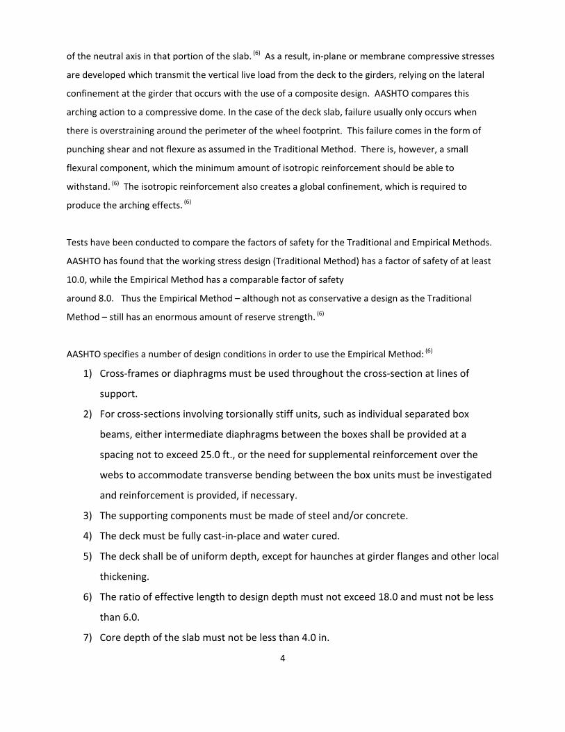
AASHTO specifies a number of design conditions in order to use the Empirical Method: (6)
1) Cross‐frames or diaphragms must be used throughout the cross‐section at lines of
support.
2) For cross‐sections involving torsionally stiff units, such as individual separated box
beams, either intermediate diaphragms between the boxes shall be provided at a
spacing not to exceed 25.0 ft., or the need for supplemental reinforcement over the
webs to accommodate transverse bending between the box units must be investigated
and reinforcement is provided, if necessary.
3) The supporting components must be made of steel and/or concrete.
4) The deck must be fully cast‐in‐place and water cured.
5) The deck shall be of uniform depth, except for haunches at girder flanges and other local
thickening.
6) The ratio of effective length to design depth must not exceed 18.0 and must not be less
than 6.0.
7) Core depth of the slab must not be less than 4.0 in.
5
8) The effective length shall not exceed 13.5 ft.
9) The minimum depth of the slab shall not be less than 7.0 in., excluding a sacrificial
wearing surface where applicable.
10) There must be an overhang beyond the centerline of the outside girder of at least 5.0
times the depth of the slab; this condition is satisfied if the overhang is at least 3.0 times
the depth of the slab and a structurally continuous concrete barrier is made composite
with the overhang.
11) The specified 28‐day strength of the deck concrete shall not be less than 4.0 ksi.
12) The deck must be made composite with the supporting structural components.
The commentary to the AASHTO LRFD specification indicates that item six in this list is the most
important parameter concerning the resistance of concrete slabs to wheel loads. Exceeding this limit
would make the deck more susceptible to cracking due to live loads.
The reinforcement requirements specified by the Empirical Method assume a deck thickness of 7.5 in.
The minimum reinforcement requirements for the bottom layer are 0.27 in2 of reinforcement per foot
of slab width (in2/ft) and 0.18 in2/ft for the top layer. However, when a slab thickness other than 7.5 in.
is used, these values appear to need to be adjusted. (6)
AASHTO Traditional Method
The traditional method is the more complex of the two design methods and leads to a more
conservative design. It assumes the live load force effects are transmitted to the supporting girders by
slab flexure. The resultant forces and stresses due to flexure are determined using the methods
outlined in Article 4.6.2.1. (6) Many of the states using this method have developed design tables that
place more reinforcement in the center of the bridge cross‐section between the girders. The
reinforcement in the secondary direction in the bottom of slabs is specified as a percentage of the
positive moment reinforcement. (6)

6
Review of Literature
The TRIS and Compendex indexes provided papers, journal articles, and magazine articles which
described new and more efficient design methods to control cracks in bridge decks. The suggestions for
crack control were not always unanimous; some directly contradicted each other. Below is a summary
of the pertinent sources and the ideas they presented.
Empirical Design Method
Csagoly and Lybas examined the main load‐carrying mechanism in concrete bridge decks and confirmed
that internal arching, not elastic plate bending, is responsible for the bulk of a bridge deck’s load‐
carrying capacity once cracking occurs. (7) These findings verify ideas presented by the Canadian
Highway Bridge Design Code in 1979, as well as the empirical design method offered in the AASHTO
Code in 1992. (1, 3)
In a separate paper, Csagoly examined the amount of reinforcement needed to adequately control
cracks in a prototype model of a thin concrete bridge deck. He found that if the bridge deck meets
certain geometrical and structural criteria set forth in the Ontario Highway Bridge Design Code, then an
isotropic reinforcement ratio of 0.3 percent satisfies both serviceability (as pertaining to crack control)
and ultimate limit states requirements of the Ontario Bridge Code. (8) More specifically Csagoly
examined both punching shear and overall vehicle weight effects for the ultimate limit state and found
only hairline cracks for service live loads. Since these cracks did not open up during his testing, the
reinforcement ratio of 0.3 percent was accepted. The current ACI temperature and shrinkage
reinforcement requirements require a 0.3 percent reinforcement ratio when the length between
movement joints is 30 ft. or less. Fang’s finite element models agree that using an isotropic
reinforcement ratio of 0.3 percent is adequate for crack control in bridge decks and he recommends not
completing any additional checks pertaining to crack control as long as the following AASHTO empirical
method criteria are satisfied: girder spacing less than 12.1 ft, span length‐to‐thickness ratio less than 15,
deck thickness of at least 9.0 in., maximum bar spacing of 12 in., and maximum diaphragm spacing of 26
feet. (9)
7
Sabnis found the empirical method to be more resistant to cracking than the traditional AASHTO
method. (10) Researchers from the Michigan and New York transportation departments have investigated
the adequacy of the empirical method and have recommended using it in all situations where the deck
falls within AASHTO’s empirical bridge deck guidelines.(7, 8, 9) Others such as Barth, Blackman, Frosch, and
Radabaugh disagree, saying that a reinforcement ratio of 0.6 percent is necessary for adequate crack
control based upon full‐scale tests and a review of previously constructed bridge decks which utilized
AASHTO’s empirical bridge deck design method. (10, 11) Based on their full‐scale tests these researchers
found that decks with a 0.6 percent reinforcement ratio most consistently resisted significant cracking.
Our survey of state deck design requirements indicates that most states – even those using AASHTO’s
empirical method – provide a deck reinforcement ratio of approximately 0.6 percent.
Transverse Cracking
We next looked at factors that affect transverse cracking and remedies to control cracking.
Saadeghvaziri and Hadidi developed finite element models that indicated that the ratio of girder to deck
stiffness is the most important factor for controlling deck cracking. (11) They would minimize this ratio by
increasing the deck thickness, decreasing girder spacing, and reducing the girder moment of inertia.(12, 13)
Many others also agreed that increasing the deck thickness reduces transverse cracking and increases
strength. (12) Krauss suggests that bridge decks be no less than 8.0 in. thick.(13) Barker, Krauss, McDonald
and Rogalla conducted laboratory and field tests showing that increasing the deck stiffness significantly
decreases the amount of transverse cracks in bridge decks. (15, 16)
Reinforcement cover is another factor affecting the probability of transverse cracks. Babaei and
Fouladgar suggest using a minimum of 2.0 in. cover to reduce the deck’s tendency to crack. (14) Other
researchers examined how reinforcement bar size and spacing affect transverse deck cracks. Many
investigators agree that using larger than No. 5 bars for reinforcement is not advisable since larger bars
are usually spaced farther apart which results in larger transverse cracks. (18, 19, 20, 21, 22, 23) Krauss, Rogalla,
Frosch and Blackman agree, saying that using more bars of smaller diameter will reduce crack width and
crack frequency. (15, 4) They also point out that the alignment of bars must also be considered. Krauss
and Rogalla state that when the top and bottom transverse bars align vertically, they form a weakened
section within the concrete that is more susceptible to cracking. (15) Others have also suggested that

8
altering the standard bar alignment by placing the top longitudinal bars above the top transverse bars
could mitigate transverse deck cracking. (16)
Summary of Current Research
The research agrees that the best way to control transverse cracking is to increase the deck stiffness in
relation to the girder stiffness. There is also a consensus that deck reinforcing bars should be No. 5 or
smaller. However, there is some disagreement as to how much steel is required in bridge decks to
control cracking. Some say a longitudinal and transverse reinforcement ratio of 0.3 percent is sufficient,
while others suggest a minimum reinforcement ratio of 0.6 percent. Most states currently utilize a
reinforcement ratio closer to 0.6 percent. Later in the report, Idaho’s reinforcement ratio will be
compared to other states’ requirements.

9
Survey of State Bridge Deck Design Methods
Next, we investigated the methods each state department of transportation has used to design bridge
decks and their design requirements. We began by searching through each state’s bridge design manual
for bridge deck design information. After examining the bridge deck design manuals, we contacted
engineers from each transportation department’s bridge design section to verify that we had recorded
the appropriate bridge deck design method for that state. The results from our initial survey are shown
below in Figure 1 and Table 1, which indicate that currently only 17 out of the 50 state DOT’s, including
Idaho, are using or occasionally using the AASHTO LRFD Empirical Method in their bridge deck designs.
Figure 1. Survey Results - DOTs’ Preferred Bridge Deck Design Methodology
17
33
Empirical Method
Other Methods

10
Table 1. Bridge Deck Design Method Survey Results
State Uses LRFD Empirical Method Method
Alabama No Custom Design Tables Alaska No Equivalent Strip Method Arizona No Elastic Method (4.6.2.1)
Arkansas No Traditional Method (9.7.3) California No Traditional Method (9.7.3) Colorado No Design Charts
Connecticut Yes Empirical Method (9.7.2) Delaware No Elastic Method (4.6.2.1)
Florida Yes Empirical Method & Traditional Method Georgia No Service Load Design Hawaii No Traditional Method (9.7.3) Idaho Yes Empirical Method (9.7.2) Illinois No Traditional Method (9.7.3) Indiana Yes Empirical Method (9.7.2)
Iowa Yes Empirical Method & Traditional Method Kansas No Traditional Method (9.7.3)
Kentucky No Traditional Method (9.7.3) Louisiana Yes-Rarely Empirical Method & Traditional Method
Maine No Precast Panels Maryland No Traditional Method (9.7.3)
Massachusetts No Traditional Method (9.7.3) Michigan Yes-Rarely Empirical Method (9.7.3)
Minnesota No Traditional Method (9.7.3) Mississippi No LRFD Strip Method
Missouri No Traditional Method (9.7.3) Montana Yes-Rarely Traditional Method (9.7.3) Nebraska Yes Empirical Method (9.7.2) Nevada No Updating Methods Now
New Hampshire No LRFD Non-Empirical New Jersey Yes-Rarely Traditional Method (9.7.3) New Mexico No Custom Design Tables
New York Yes-Rarely Empirical Under Certain Conditions North Carolina No Traditional Method (9.7.3) North Dakota No Traditional Method (9.7.3)
Ohio No Traditional Method (9.7.3) Oklahoma Yes-Rarely Traditional Method (9.7.3)
Oregon No Traditional Method (9.7.3) Pennsylvania No Traditional Method (9.7.3) Primarily Rhode Island No Elastic Method (4.6.2.1)
South Carolina No Traditional Method (9.7.3) South Dakota No Traditional Method (9.7.3)
Tennessee No Elastic Method (4.6.2.1) Texas Yes-Rarely Traditional Method (9.7.3) Utah Yes Empirical Method & Traditional Method
Vermont Yes-Rarely Traditional Method (9.7.3) Virginia No Traditional Method (9.7.3)
Washington No Traditional Method (9.7.3) West Virginia Yes Empirical Method & Traditional Method
Wisconsin Yes-Rarely Empirical Method & Traditional Method Wyoming No Traditional Method (9.7.3)
*The numbers in the preferred method column refer to the section of the AASHTO LRFD code describing that method.
11
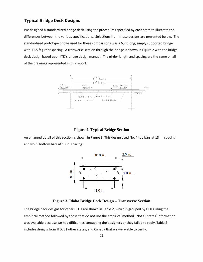
Typical Bridge Deck Designs
We designed a standardized bridge deck using the procedures specified by each state to illustrate the
differences between the various specifications. Selections from those designs are presented below. The
standardized prototype bridge used for these comparisons was a 65 ft long, simply supported bridge
with 11.5 ft girder spacing. A transverse section through the bridge is shown in Figure 2 with the bridge
deck design based upon ITD’s bridge design manual. The girder length and spacing are the same on all
of the drawings represented in this report.
CL CL1 1 .5 f t .
1 1 .0 f t .B e a m S p a c in g
E ffe c t iv e S p a n
N o . 5 @ 1 3 .0 in .
N o . 4 @ 1 3 .0 in .
9 .0 in .0 .5 in .
T o ta l S la b S a c r if ic ia l W e a r in gS u rfa c eT h ic k n e s s
8 .5 in .D e s ig n S la bT h ic k n e s s
2 .0 in .
1 .0 in .
N o . 5 @ 1 3 .0 in .
N o . 4 @ 1 3 .0 in .
Figure 2. Typical Bridge Section
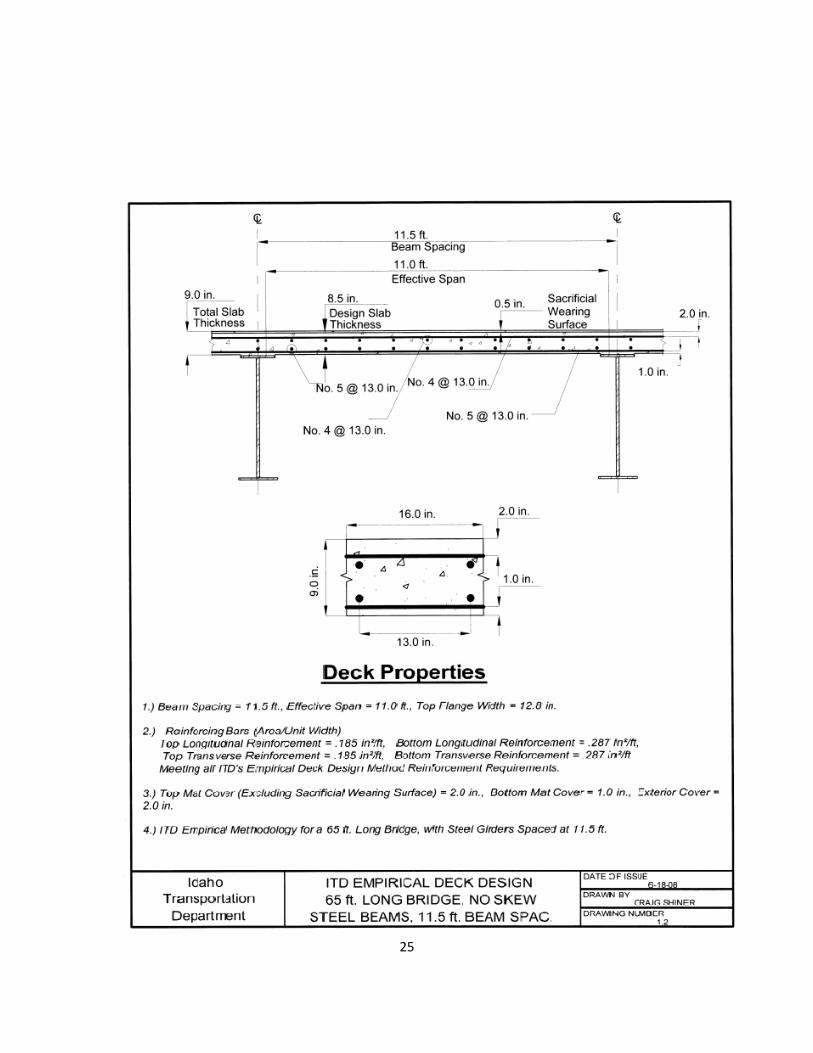
An enlarged detail of this section is shown in Figure 3. This design used No. 4 top bars at 13 in. spacing
and No. 5 bottom bars at 13 in. spacing.
Figure 3. Idaho Bridge Deck Design – Transverse Section
The bridge deck designs for other DOTs are shown in Table 2, which is grouped by DOTs using the
empirical method followed by those that do not use the empirical method. Not all states’ information
was available because we had difficulties contacting the designers or they failed to reply. Table 2
includes designs from ITD, 31 other states, and Canada that we were able to verify.

12
Table 2. Bridge Deck Designs for Standard Prototype Bridge*
Uses LRFD Total Offsets Upper Bars Lower Bars
Empirical Girder Deck Top and Bottom Trans. Long. Trans. Long.
DOT Method Spacing (ft) Thick (in.) Bars size@spacing size@spacing size@spacing size@spacing
Canada Yes 11.5 8.0 Yes No. [email protected] No. [email protected] No. [email protected] No. [email protected]
Connecticut Yes 11.5 8.5 Yes No. 4@12 No. 4@12 No. 5@12 No. 5@12
Florida Yes 11.5 8.0 Yes No. 5@12 No. 5@12 No. 5@12 No. 5@12
Idaho Yes 11.5 9.0 No No. 4@13 No. 4@13 No. 5@13 No. 5@13
Indiana Yes 11.5 8.0 No No. 4@12 No. 4@12 No. 5@12 No. 5@12
Michigan Yes 11.5 9.0 No No. 4@13 No. 4@13 No. 5@13 No. 5@13
Nebraska Yes 11.5 8.5 Yes No. 4@12 No. 4@12 No. 5@12 No. 5@12
New Jersey Yes 11.5 10.0 Yes No. 6@9 No. 5@10 No. 6@9 No. 5@10
New York Yes 11.0 9.5 Yes No. 4@8 No. 4@8 No. 4@8 No. 4@8
Oklahoma Yes 11.5 8.0 Yes No. 4@12 No. 4@12 No. 5@12 No. 5@12
Texas Yes 11.5 8.5 No No. 4@13 No. 4@13 No. 5@13 No. 5@13
Utah Yes 11.5 8.0 Yes No. 4@12 No. 4@12 No. 5@12 No. 5@12
Vermont Yes 11.5 8.5 No No. 5@12 No. 5@12 No. 5@12 No. 5@12
West Virginia Yes 11.5 8.0 Yes No. 5@6 No. 5@6 No. 5@6 No. 5@6
Arizona No 11.5 9.5 Yes No. 5@5 No. 5@9 No. [email protected] No. 5@9
Colorado No 11.5 8.75 Yes No. 5@5 No. 5@5 No. 5@5 No. [email protected]
Georgia No 11.5 8.5 No No. 5@5 No. 4@ 8.5 & 5 No. 5@5
No. 4@ 8.5 & 5
Kansas No 11.5 8.5 Yes No. 5@5 No. 5@5 No. 5@5 No. 5@5
Louisiana No 11.5 8.0 Yes No. [email protected] No. [email protected] No. [email protected] No. 4@ 4 & 6.5
Maine No 11.5 10.5 Yes No. 5@6 No. 5@15 No. 5@6 No. 5@8
Maryland No 11.5 10.0 Yes No. 5@5 No. [email protected] No. 5@5 No. 5@ 11.5 & 10
Massachusetts No 11.5 9.5 No No. 5@5 No. 4@ 8&4.5 No. 5@5
No. 4@ 8 & 4.5
Minnesota No 11.5 9.5 Yes No. 5@5 No. 4@18 No. 5@7 No. 4@6
Montana No 11.5 8.5 Yes No. 6@7 No. [email protected] No. 6@7 No. 4@ 5 & 7.5
Nevada No 11.5 8.5 Yes No. 6@6 No. 6@6 No. 5@6 No. 5@7
New Mexico No 11.5 10.0 Yes No. 5@6 No. 4@6 No. 5@6 No. 4@ 12 & 6
Ohio No 11.5 9.5 No No. 5@5 No. [email protected] No. 5@5 No. 5@10
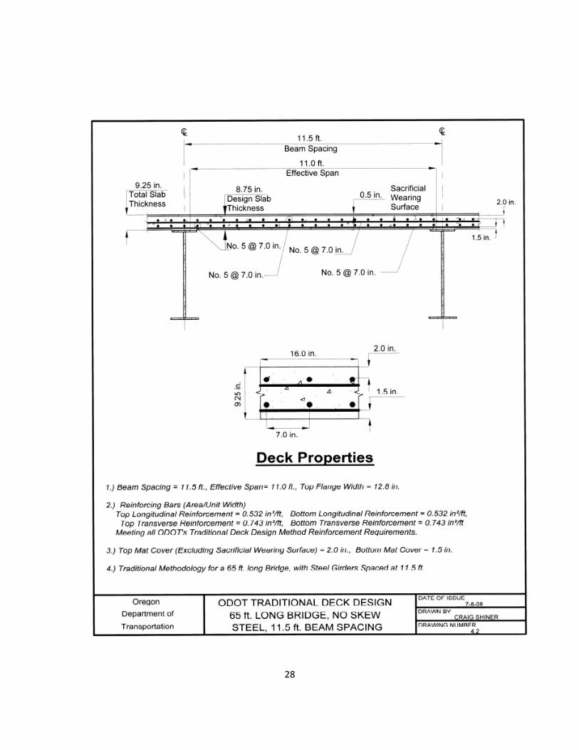
Oregon No 11.5 9.25 No No. 5@5 No. 5@7 No. 5@5 No. 5@7
South Carolina No 11.5 8.5 Yes No. 5@5 No. 5@9 No. [email protected] No. 5@9
Washington No 11.5 8.0 Yes No. 5@6 No. 5@6 No. 5@6 No. 5@6
Wisconsin No 11.5 9.5 Yes No. [email protected] No. 4@7 No. [email protected] No. 4@7
Wyoming No 11.5 8.5 Yes No. 6@12 No. 6@7 No. 5@12 No. 5@7
*We did not receive complete responses from all states. The states included in this table are those that provided enough information to complete a deck design based on their standards.

13
The results of this design study indicate that very few bridge deck designs were identical to Idaho’s
design. Of the seventeen states that use the Empirical Method, only Connecticut, Indiana, Michigan,
Nebraska, Oklahoma, Texas, and Utah’s designs were similar to Idaho’s design. The designs from
Michigan, Texas, and Idaho used identical amounts of reinforcement. The designs from Connecticut,
Indiana, Nebraska, Oklahoma, and Utah used the same sizes of reinforcement as Michigan, Texas, and
Idaho, but with slightly smaller bar spacing, e.g. 12‐inch bar spacing rather than 13‐inch bar spacing.
Comparing Idaho’s design to the designs from states that did not use the empirical method shows even
greater variations with some states requiring three or even four times as much steel for the same deck
area.
Example deck designs from two states adjacent to Idaho – Washington and Oregon – are shown in
Figure 4. Neither of these two states uses the empirical deck design method. Note that both designs
utilize much smaller bar spacing than the Idaho design, the top and bottom bars in the Washington
design are offset, and the top longitudinal bars in the Oregon design are above the top transverse bars.
Figure 4. Neighboring States Bridge Deck Design - Transverse Sections
Offsetting the top bars from the bottom bars reduces the tendency for cracks to occur during the
consolidation of the concrete. Oregon DOT and New York DOT do not offset the top bars from the
bottom bars, but they do specify that the longitudinal bars be placed above the transverse bars in both
the top and bottoms layers in an attempt to minimize longitudinal shrinkage cracks.
14
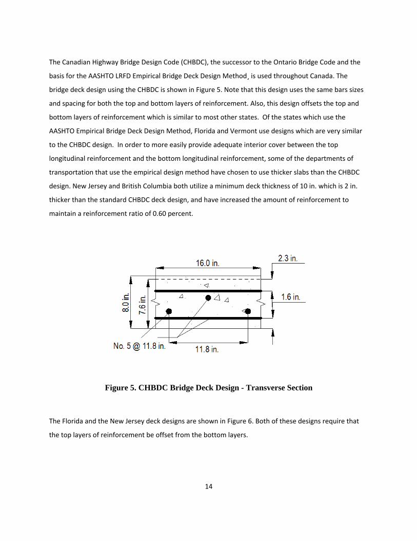
The Canadian Highway Bridge Design Code (CHBDC), the successor to the Ontario Bridge Code and the
basis for the AASHTO LRFD Empirical Bridge Deck Design Method¸ is used throughout Canada. The
bridge deck design using the CHBDC is shown in Figure 5. Note that this design uses the same bars sizes
and spacing for both the top and bottom layers of reinforcement. Also, this design offsets the top and
bottom layers of reinforcement which is similar to most other states. Of the states which use the
AASHTO Empirical Bridge Deck Design Method, Florida and Vermont use designs which are very similar
to the CHBDC design. In order to more easily provide adequate interior cover between the top
longitudinal reinforcement and the bottom longitudinal reinforcement, some of the departments of
transportation that use the empirical design method have chosen to use thicker slabs than the CHBDC
design. New Jersey and British Columbia both utilize a minimum deck thickness of 10 in. which is 2 in.
thicker than the standard CHBDC deck design, and have increased the amount of reinforcement to
maintain a reinforcement ratio of 0.60 percent.
Figure 5. CHBDC Bridge Deck Design - Transverse Section
The Florida and the New Jersey deck designs are shown in Figure 6. Both of these designs require that
the top layers of reinforcement be offset from the bottom layers.

15
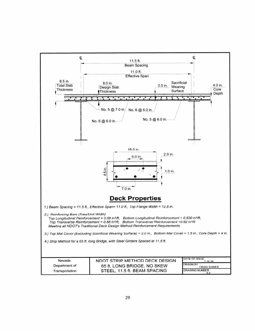
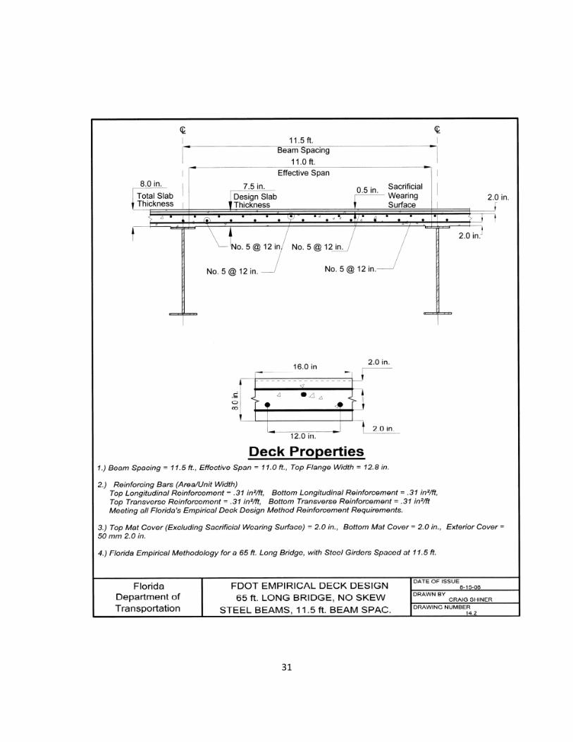
Figure 6. Bridge Decks Designed Using LRFD Empirical Method ‐ Transverse Sections
Two bridge deck designs from states that do not use the empirical method are shown in Figure 7. Both
of these designs use considerably more steel for a given deck area than the Idaho design. In addition,
these designs also require that the top layers of reinforcement be offset from the bottom layers.
Figure 7. Bridge Deck Designs Using Traditional Methods – Transverse Sections
16
Crack Control Methods Survey Results From States that Responded
Some states that responded to our email survey provided additional information that is relevant to this
report. Those additional comments are as follows:
New Mexico:
• To reduce the severity of shrinkage cracking in the deck slabs of continuous beam bridges, they place deck slabs sequentially. The sequence specified in the plans requires that positive moment areas be placed first and that negative moment areas be placed last. NMDOT has used thinner decks in a few instances over the years.
• They have found that thinner decks do not have the long‐term durability of the standard deck slab details.
• To reduce transverse cracking in newly constructed bridge decks, they offset the transverse bars in the top and bottom mats of deck slab reinforcement by ½ of the bar spacing.
Washington State:
• The minimum slab thickness is established in order to ensure that overloads on the bridge will not result in premature slab cracking. Their minimum deck thickness is 7.5 in. (17)
Montana:
• They suggest that transverse post tensioning minimizes cracking. • They use smaller diameter bars for the same steel cross sectional area to provide better crack‐
size control. (18)
Oregon:
• ODOT does not use the empirical design method for deck reinforcing steel. They specify that excessive deck cracking, apparently due to under reinforcement, precludes the use of this method until further notice.
• The preferred orientation of the top mat of deck steel has the longitudinal bars on top. This orientation places the longitudinal bars closer to the surface thereby reducing the size of deck shrinkage cracks. (19)
Nevada:
• The top and bottom transverse reinforcing steel is offset, preferable at half the spacing, so that the top mat is not placed directly above the bottom mat. This requirement is intended to reduce the potential for transverse deck cracking due to concrete consolidation. (20)

17
Nebraska:
• They have not seen any increased cracking in their bridge decks with the use of the empirical method. They still do see some cracking, but believe it is due to other factors (composite design, pouring sequence, type of cement, curing, temperature at the time of pour etc.) rather than the method of design. (21)
New York:
• Since they started using isotropic deck reinforcement they did not notice an increase or decrease in transverse cracking. Since transverse deck cracking is a nationwide problem, they attribute that to many other causes beside the design method used. (3)
Florida:
• To minimize shrinkage and deflection cracking in cast‐in‐place decks, they designate a deck casting sequence for continuous flat slab and beam/girder superstructures and simple span beam/girder superstructures with continuous decks. The direction of each deck pour is specified to minimize cracking in the freshly poured concrete and previously cast sections of deck. The sequence should result in construction joints spaced at locations of the points of contra‐flexure, unless limited by the size of the pour. (22)

18
Recommendations: Deck Reinforcing
Our research determined that there is a wide variation in the methods that states currently use to
design their bridge decks. Our literature search and surveys revealed that 17 states make some use of
the AASHTO LRFD empirical deck design method, while 33 states continue to rely on some form of
AASHTO LRFD traditional deck design.
For those states using traditional methods, a key issue appears to be the application of provisions of
AASHTO LRFD Article 5.7.3.4 Control of Cracking by Distribution of Reinforcement for the traditional
design method. While some states appear to closely follow the crack control provisions in Article
5.7.3.4, other states rely on standardized historical amounts and spacing of steel reinforcement. In
addition, the provisions of this Article and the amount and spacing of reinforcement require a larger
reinforcement ratio and closer bar spacing than the empirical deck design method. Trial designs
included in this research also confirm this inconsistency, which can be seen when comparing designs
from Florida and Nevada, noting the large discrepancies in their reinforcement ratios.
Research by Csagoly and others considered crack control under service live loads for empirical deck
design. (7, 8) Reportedly some states feel the amounts of steel provided by the empirical method are
insufficient to control this type of cracking. On the other hand, some states feel the provisions of Article
5.7.3.4 are excessive.
Research by Frosh indicates that for empirical design a closer spacing and minimum bar size is necessary
to control cracking due to shrinkage and drying. (4, 29)
Based on our literature review and survey, Idaho may want to consider altering its bridge deck design
requirements to minimize cracking associated with deck design, thereby increasing the cost‐
effectiveness and durability of its bridge deck designs.
It appears the 0.3 percent reinforcement ratio prescribed by the AASHTO empirical deck design
procedure is adequate for strength requirements; however it is smaller than the 0.6 percent
reinforcement ratio recommended by other researchers to control cracking. 4, 23) The AASHTO empirical
deck design method specifies a minimum deck thickness of 7.0 in. and a minimum deck thickness‐to‐
span ratio of 1:20. These requirements affect the deck‐to‐girder stiffness ratio. Many researchers agree
that increasing this ratio is the primary method to control cracking.(11)
19
We believe the following recommendations will help the Idaho Transportation Department control
concrete bridge deck cracking more effectively.
• Researchers and an analysis of states current practices agree that the reinforcement ratios for the deck should be increased by limiting the top and bottom, longitudinal and transverse bar spacing to a maximum of 6 in. using No. 4 bars. ITD currently utilizes a 13‐in. bar spacing in all directions with No. 4 bars. For an 8 in. thick deck, this amounts to an approximate reinforcement ratio of 0.18 percent in each direction. Although this provides sufficient strength in accordance with the empirical design method, many researchers agree that a low reinforcement ratio, such as Idaho’s, will result in shrinkage and drying cracks.(23, 4) Reducing the spacing to six inches will reduce shrinkage and drying cracks, while putting the reinforcement ratio on par with most of the states that we surveyed which specify a minimum reinforcement ratio around 0.6 percent. The Indiana Department of Transportation conducted full scale tests and found that a 6 in. bar spacing will increase the frequency of the cracks but greatly decrease the cracks’ width to approximately 16 mils..(13, 4) Most states’ bar spacing requirements conform to these recommendations; however our survey did not investigate the reasons for their spacing requirements.
• ITD currently utilizes an 8 in. minimum bridge deck thickness.1 Increasing the minimum deck thickness to 8.5 in. would put Idaho on par with the average deck thickness used by the majority of other states as well as slightly increase their deck stiffness. AASHTO currently requires a minimum deck thickness of 7 in. However many researchers agree that this will provide insufficient deck stiffness for crack control. (12) Our review of literature indicates that reducing the girder‐to‐deck stiffness ratio by increasing the deck stiffness is the most effective method to limit deck cracking.(11)
• The top and bottom bars should not be placed in a vertical plane that may encourage cracking. Rather, bars should be offset to enhance concrete consolidation.(15, 16) This is practiced by many state agencies; currently 33 of the 47 responding states offset their top and bottom bars.
Adopting these recommendations would allow ITD to use AASHTO’s empirical deck design method with
the same bar sizes and spacing in the top and bottom layers while providing greater crack control.
These recommended changes would align ITD’s design practice with the majority of other states’
practices.
1 Idaho’s deck design for the standard prototype bridge in Table 2 is 8.5 in. thick to satisfy deck-to-girder stiffness ratio requirements.

20
Summary and Conclusions
The goal of this report was to address ITD’s inquiries regarding the effectiveness of the AASHTO
empirical method of bridge deck design with regards to crack control. We examined the causes and
types of bridge deck cracking which enabled us to narrow our research towards transverse cracking,
which is the most common type of cracking in bridge decks.
We reviewed the two current methods of bridge deck design: the empirical method and traditional
method. The traditional method is the more conservative of the two. Although the empirical method
has many requirements for use, many researchers agreed that the empirical method is not sufficient for
crack control. In addition to the rebar spacing and size addressed in the empirical and traditional
methods, most researchers agree that the ratio of deck to girder stiffness significantly affects deck
cracking.
We also conducted a survey to determine the bridge deck design methods used by other states. Most
states use a larger rebar size at a smaller spacing than is required by ITD. These findings led us to
recommend increasing the bar size and decreasing the bar spacing as well as using a thicker deck and
staggering the bars.
Increasing the amount and size of reinforcement for a given bridge should decrease bridge deck
cracking, which will ultimately reduce bridge maintenance costs and extend bridge life. It will also
reduce the severity of cracking, resulting in a finer mesh of cracks which are closer together and much
smaller in width.
21
BIBLIOGRAPHY
1. AASHTO Highway Subcommittee on Bridges and Structures. AASHTO LRFD Bridge Design Specifications. 4, 2007, pp. 9.8‐9.12. 2. Barnes, C. "Practical Considerations for Dealing with Concrete Cracks in Decks." Structure: Concrete. (July 2008):26‐27.
3. New York State Department of Transportation. New York State Department of Transportation Bridge Manual (US Customary Edition). New York State Department of Transportation. 2008. https://www.nysdot.gov/divisions/engineering/structures/manuals/bridge‐manual‐usc. Accessed July, 2008.
4. Frosch, R., Blackman, D. and Radabaugh, R. Investigation of Bridge Deck Cracking in Various Bridge Superstructure Systems. West Lafayette, IN: Purdue University, FHWA/IN/JTRP‐2002/25. 2003.
5. Barker, J. M. “Stiffer Bridges Result in Slower Bridge Deck Deterioration.” Aspire. Vol. 2, No. 2 (Spring 2008): 53. 6. American Association of State Highway and Transportation Officials (AASHTO). AASHTO LRFD Bridge Design Specifications, 3rd Edition. Washington, D. C.: American Association of State Highway and Transportation Officials, 2005. 7. Csagoly, P. F. and Lybas, J. M. "Advanced Design Method for Concrete Bridge Deck Slabs." Concrete International, Vol. 11, No. 5 (May 1989): 53‐64. 8. Csagoly, P. F. Design of Thin Concrete Deck Slabs by the Ontario Highway Bridge Design Code. Toronto, ON: Research and Development Branch, Ontario Ministry of Transportation, 1979.
9. Fang, L. K., Worley, J. A., Burns, N. H. and Klingner, R. E. Behavior of Ontario‐Type Bridge Decks on Steel Girders.Austin, TX: Center for Transportation Research, Texas University at Austin, CTR‐3‐5‐83‐ 350‐1, 1986.
10. Sabnis, G. M. Performance of Concrete Bridge Deck Slabs Using Isotropic and Standard AASHTO Procedures. University Park, PA : Pennsylvania Transportation Institute, Pennsylavania, 2001. FHWA‐PA‐2001‐016‐97‐4 (6).
11. Saadeghvaziri, A. M. and Hadidi, R. "Transverse Cracking of Concrete Bridge Decks: Effects of Design Factors." Journal of Bridge Engineering. Vol. 10, No.5 (Sept./Oct. 2005): 511‐519.
12. Brotchie, J. F. and Holley, M. J. "Membrane Action in Slabs." pg. 345‐377 In. International Symposium on the Cracking, Deflection, and Ultimate Load of Concrete Slab Systems. Detroit, MI: American Concrete Institute, 1971.
22
13. McDonald, D. B., Krauss, P. D. and Rogalla, E. A. "Early‐Age Transverse Deck Cracking. " Concrete International. Vol. 17, No. 5 (May 1995): 49‐51.
14. Babaei, K. and Fouladgar, A. M. "Solutions to Concrete Bridge Deck Cracking." Concrete International. Vol. 19, No. 7 (July 1997):
15. Krauss, P. D. and Rogalla, E. A. Transverse Cracking in Newly Constructed Bridge Decks. Washington, D. C.: Transporation Research Board, NCHRP Report 380, 1996.
16. Ramey, G. E., Wolff, A. R. and Wright, R. L. Structural Design Actions to Mitigate Bridge Deck Cracking. Practice Periodical on Structural Design and Construction. Vol. 2, No. 3 (August 1997): 118‐124. 17. Fahoum, J. Washington State Department of Transportation Bridge Design Manual. Olympia, WA: Washington State Department of Transportation. [Online] November 2006. http://www.wsdot.wa.gov/Publications/Manuals/M23‐50.html. Accessed July 8, 2008.
18. Montana Department of Transportation. Bridge Design Standards. Helena, MT: Montana Department of Transportation. http://www.mdt.mt.gov/other/bridge/external/design‐stds‐manual/design_stds_manual.pdf, Accessed July, 2008.
19. Oregon Department of Transportation. Bridge Design and Drafting Manual. Salem, OR: Oregon Department of Transportation. 2004. http://www.oregon.gov/ODOT/publications.shtml. Accessed July 8, 2008.
20. Nevada Department of Transportation. Structures Manual. Carson City, NV: Nevada Department of Transportation. 2008. http://www.nevadadot.com/divisions/011/, Accessed July, 2008.
21. Nebraska Department of Roads. Bridge Office Policies and Procedures. Lincoln, NE, Nebraska Department of Roads. 2008. http://www.nebraskatransportation.org/design/bridge/bopp/2008_BOPP_Manual(web).pdf. Accessed July, 2008.
22. Florida Department of Transportation. Florida Department of Transportation: Structures Design. Florida Department of Transportation. [Online] http://www.dot.state.fl.us/officeofdesign/Structures/. Accessed July, 2008.
23. Barth, F and Frosch, R.. Control of Cracking in Concrete Structures. Farmington Hills, MI: American Concrete Institute, ACI 224R‐01, 2001.
24. Issa, M. A. "Investigation of Cracking in Concrete Bridge Decks at Early Ages." Journal of Bridge Engineering.Vol. 4, No. 2 (May 1999): 116‐124.
25. Kwak, H. G. and Seo, Y. J. "Shrinkage Cracking at Interior Supports of Continuous Pre‐Cast Pre‐Stressed Concrete Girder Bridges." Construction and Building Materials, Vol. 16, No. 1 (February 2002): 35‐47.

23
26. Petrou, M. F., Harried, K. A., and Schroeder, G. E. "Field Investigation of High‐
Performance Concrete Bridge Decks in South Carolina". Transportation Research Record No. 1770. (2001): 12‐19..
27. Dakhil, F. H. and Cady, P. D. "Cracking of Fresh Concrete as Related to Reinforcement." ACI Journal. Vol. 72, No. 8 (August 1975): 421‐428.
28. Babaei, K. and Hawkins, N. M. Evaluation of Bridge Deck Protective Strategies. Washington D.C.: Transportation Research Board, NCHRP No. 297, 1987. 29. Schmitt, T. R. and Darwin, D. D. Cracking in Concrete Bridge Decks. Topeka, KS: Kansas Department of Transportation, No. K‐TRAN:KU‐94‐1, 1995.
30. Shing, P. B. and Abu‐Hejleh, N. Cracking in Bridge Decks: Causes and Mitigation Denver, CO: Research Branch, Colorado Department of Transportation, CDOT‐DTD‐R‐99‐ 8, 1999.
31. French, C. E., Le, Q. T. C., Eppers, L. J. and Hajjar, J. Transverse Cracking in Bridge Decks.. Minneapolis, MN: University of Minnesota, MN/RC‐1999‐05, 1999.
32. Altay, A. K. and Bush, T. J. Cracking Concerns of Reinforced Concrete Bridge Decks. Buffalo, NY: Department of Civil and Environmental Engineering, University of Buffalo.
33. Jansson, P. O. Performance Evaluation of Isotropic Bridge Decks. Lansing, MI: Michigan Department of Transportation, R‐1515, 2008.
34. Pezze, F. P. and Fu, G. Comparative Performance of AASHTO and Lightly Reinforced Bridge Deck Slabs. Albany, NY: New York State Department of Transportation, 1992.
35. Needham, D. E. Performance Evaluation of Isotropic Bridge Decks (Ontario Design). Lansing, MI: Michigan Department of Transportation, R‐1352, 1997.
24
APPENDIX – Bridge Deck Designs
Idaho Transportation Department
Florida Department of Transportation
Maine Department of Transportation
New Jersey Department of Transportation
Nevada Department of Transportation
Oregon Department of Transportation
Washington Department of Transportation
Canadian Highway Bridge Design Code
25

26

27
28
29

30
31

32


