Accepted Manuscript
Improving 3D printing process of lemon juice gel based on fluid flow numericalsimulation
Fanli Yang, Chaofan Guo, Min Zhang, Bhesh Bhandari, Yaping Liu
PII: S0023-6438(18)31089-2
DOI: https://doi.org/10.1016/j.lwt.2018.12.031
Reference: YFSTL 7692
To appear in: LWT - Food Science and Technology
Received Date: 17 August 2018
Revised Date: 25 November 2018
Accepted Date: 9 December 2018
Please cite this article as: Yang, F., Guo, C., Zhang, M., Bhandari, B., Liu, Y., Improving 3D printingprocess of lemon juice gel based on fluid flow numerical simulation, LWT - Food Science andTechnology (2019), doi: https://doi.org/10.1016/j.lwt.2018.12.031.
This is a PDF file of an unedited manuscript that has been accepted for publication. As a service toour customers we are providing this early version of the manuscript. The manuscript will undergocopyediting, typesetting, and review of the resulting proof before it is published in its final form. Pleasenote that during the production process errors may be discovered which could affect the content, and alllegal disclaimers that apply to the journal pertain.
MANUSCRIP
T
ACCEPTED
ACCEPTED MANUSCRIPT
Improving 3D Printing Process of Lemon Juice Gel Based on Fluid Flow Numerical 1 Simulation 2
3
Fanli Yanga, Chaofan Guoa, Min Zhanga,b*, Bhesh Bhandaric, Yaping Liu d 4
5
aState Key Laboratory of Food Science and Technology, Jiangnan University, 14122 6
Wuxi, Jiangsu, China 7
bJiangsu Province Key Laboratory of Advanced Food Manufacturing Equipment and 8
Technology, Jiangnan University, China 9
cSchool of Agriculture and Food Sciences, University of Queensland, Brisbane, QLD, 10
Australia 11
d Guangdong Galore Food Co. Ltd, Zhongshan 528447, China 12
13
14
*Corresponding author: Dr. Min Zhang, Professor of School of Food Science and 15
Technology, Jiangnan University, 214122 Wuxi, P. R. China. 16
Tel.: 0086-510-85877225; Fax: 0086-510-85877225; 17
E-mail: [email protected] 18
19
MANUSCRIP
T
ACCEPTED
ACCEPTED MANUSCRIPT
Abstract 20
Food 3D printing has received attention as a novel field in recent years, bringing 21
new ideas and opportunities for the development and transformation of food 22
processing technology. This work investigated the moisture and rheological properties 23
of lemon juice gels with different starches by experimental studies and simulated the 24
effect of different material properties and process parameters (material viscosity and 25
relaxation time, inlet volume flow rate and nozzle diameter) on the velocity, shear rate 26
and pressure fields in the flow channel by the POLYFLOW software. Results showed 27
that with the addition of different kinds of starches, the viscosity and mechanical 28
properties of the lemon juice gel were varied. Adding potato starch altered fluidity 29
with different relative degree of bound or immobilized water of lemon juice gel. 30
According to the simulation study, in the same shape of the flow path, the velocity and 31
shear velocity fields were determined by the inlet volume flow rate. The change of 32
different process parameters was found to cause changes in pressure field in the flow 33
channel to varying degrees, and the change of the nozzle diameter had the greatest 34
influence on the pressure distribution. In addition, the extruded material exhibited 35
swelling phenomenon. 36
Keywords: 3D printing, Lemon juice gel, POLYFLOW, Numerical simulation, NMR, 37
Rheology 38
39

MANUSCRIP
T
ACCEPTED
ACCEPTED MANUSCRIPT
1. Introduction 40
Three-dimensional (3D) printing, also known as additive layer manufacturing, is 41
a new rapid prototyping technology, which integrates computer technology, precision 42
drive technology, numerical control technology and material science technology. In 43
the process of printing, the material is usually passed through a nozzle whose position 44
is controlled by a shape design model (Lee, Jia, & Chua, 2017). There are many 45
unique advantages of application of 3D printing in food field, such as food structure 46
customization, customized and digitalized nutrition (Godoi, Prakash, & Bhandari, 47
2016), broadening the source of food raw materials, and shortening the food supply 48
chain (Chen, 2016; Jia, Wang, Mustafee, & Hao, 2016). 49
There are several types of raw material formats used in 3D printing such as 50
powder and paste. For powder materials, the printing methods used can be categorized 51
as selective sintering (Gray, 2010), binder jetting (Yang, Wu, & Liu, 2001) and 52
hot-melt extrusion (Lanaro et al., 2017) methods. These methods are reported for 53
printing powder materials, such as sugar and chocolates (Sun, Zhou, Huang, Fuh, & 54
Hong, 2015). In the paste method extrusion, the material is ejected from the nozzle by 55
pressure. The extrusion method can be divided into three categories: (1) rotary screw 56
extrusion, (2) time pressure dispensing and (3) positive displacement (Liu, Zhang, 57
Bhandari, & Wang, 2017). In the rotary screw extrusion method, the extrusion of food 58
materials is driven by a rotational screw, where the extrusion rate is determined by the 59
speed of motor. This method feeds continuously and is suitable for materials with a 60

MANUSCRIP
T
ACCEPTED
ACCEPTED MANUSCRIPT
wide viscosity range. However, it is very troublesome to clean and maintain in 61
practice. In addition, the material is directly in contact with the machine, which can 62
have potential food safety problems. In the time pressure dispensing method, the air 63
pressure controls the flow of food materials. The equipment used in this method is 64
cheap and easy to operate. However, it is difficult to fill/refill materials with high 65
viscosity without air bubbles (Sun, Zhou, Yan, Huang, & Lin, 2018). In the positive 66
displacement method, a piston connected to a stepping motor moves down and 67
extrudes the material out of nozzle. The material is stored in a special charging barrel 68
to facilitate the cleaning of the equipment. Moreover, this method has a good 69
sensitivity and high accuracy due to the direct connection between the piston and 70
stepping motor (Lille, Nurmela, Nordlund, Metsä-Kortelainen, & Sozer, 2018). 71
The POLYFLOW software based on finite element method (FEM) has powerful 72
functions in solving non-Newtonian fluid and nonlinear flow problems (Wilczyński, 73
Laczyński, & Czaplarski, 1998). This software has been widely used for 74
simulating/modeling of plastics processing (Wilczyński & Tyszkiewicz, 1996), 75
screw-based extrusion (T. Chen et al., 2017) and pipe flow simulation (Filali, Khezzar, 76
Siginer, & Nemouchi, 2012). For syringe-based extrusion 3D printing process, the 77
extruding process can be regarded as a pipe flow situation, and thus can be modeled 78
by FEM. Recently, 3D printing is being widely investigated for the application in food 79
sector. Many kinds of food materials have been printed using extrusion-based printing 80
technology, such as processed cheese (Le Tohic et al., 2017), pectin gel 81

MANUSCRIP
T
ACCEPTED
ACCEPTED MANUSCRIPT
(Vancauwenberghe et al., 2017), mashed potatoes (Liu, Zhang, Bhandari, & Yang, 82
2017), fish surimi gels (Wang, Zhang, Bhandari, & Yang, 2017), fruit-based snacks 83
(Derossi, Caporizzi, Azzollini, & Severini, 2017), chocolate (Hao et al., 2010; Li et 84
al., 2014) and many other food products (Calvert, 2016). It is worth noting that these 85
materials are pseudoplastic before gelation and should be considered viscoelastic after 86
gelation. In addition, because of the closed environment of the printer, it is difficult to 87
observe the fluid characteristic changes of material flow during 3D printing process. 88
Therefore, the predictability of the flow properties of materials is important to 89
understand the 3D printing. Based on our previous study, lemon juice gel prepared 90
from lemon juice and starch was found to be suitable for 3D printing (F. Yang, Zhang, 91
Bhandari, & Liu, 2018). Thus, the effect of the addition of different starches on the 92
rheological properties of lemon juice gel was studied in this work. POLYFLOW 93
software was used to simulate the fluid characteristic of inks in the flow channel of 94
the positive displacement 3D printers under different technological parameters 95
(viscosity, relaxation time, inlet volume flow rate ratio and nozzle diameter), to 96
provide a theoretical basis for 3D printing of food materials. 97
98
2. Materials and Methods 99
2.1. Raw Material 100
Lemon juice was provided by Jiahao Co. Ltd. Guangdong, China. The moisture 101
content of the lemon juice was 59.82 g/100 g (determined by the vacuum-drying 102

MANUSCRIP
T
ACCEPTED
ACCEPTED MANUSCRIPT
method). The pH of lemon juice was measured as 2.28. 103
Potato starch, sweet potato starch, wheat starch and corn starch were purchased 104
from Shanghai Tianyu Food Co. Ltd and stored at normal atmospheric temperature. 105
The moisture content determined by vacuum-oven drying method was 13.47±0.46 106
g/100g for potato starch, 14.35±0.48 g/100g for sweet potato starch, 12.96±0.55 107
g/100g for wheat starch and 12.83±0.58 g/100g for corn starch. Lemon juice was 108
firstly mixed with different kinds of starches (15 g/ 100g ) and then homogenized by 109
using a mixer (ULTRA-TURRAX® IKA® T18 basic, Model: T18BS25, Germany). 110
Afterwards, mixtures were transferred to glass containers and cooked in a water bath 111
for 15 minutes until the center temperature reached to 75±2°C. During the cooking 112
process, containers were wrapped with food grade plastic protective films to prevent 113
the water loss. Finally, samples were cooled down to room temperature to form a 114
weak gel-like structure and then stored at 4 °C for forth coming test and printing 115
process. These sample preparing methods are based on former study (Yang et al., 116
2018). 117
2.2. Low-field nuclear magnetic resonance (NMR) analysis 118
A low field pulsed NMI 20 analyzer (Shanghai Niumag Corporation, China) at 119
22.6 MHz was used in this experiment for determining status of moisture in the 120
sample. The measurement method and parameters setting were same as previous 121
study (Yang et al., 2018). Each sample (about 5 g) was analyzed three times. 122
2.3. Rheological measurements 123

MANUSCRIP
T
ACCEPTED
ACCEPTED MANUSCRIPT
Rheological measurements of samples were undertaken by a hybrid rheometer 124
(Discovery HR-3, DHR, TA Instruments, USA) equipped with a parallel plate 125
(diameter=20 mm). The viscosity and dynamic viscoelastic measurements were 126
carried out similar to previous study (Yang et al., 2018). Before measurements, 127
samples were rested at 25 °C for 2 min. The viscosity parameters were obtained in the 128
shear rate ranging from 0.1 to 100/s. Dynamic viscoelastic properties were 129
characterized at frequencies from 0.01 to 10 rad/s, and all measurements were 130
performed within the identified linear viscoelastic region and made at 0.4% strain. 131
Experiments were conducted in triplicate for each type of sample. 132
2.4. POLYFLOW software Numerical analysis 133
2.4.1. Simulation scheme 134
The viscosity of materials, the inlet volume rate and the nozzle diameter are all 135
important factors that affect parameters of the flow channel. In this work, the 136
influence of different process parameters on rheological parameters in a convective 137
channel was investigated by changing certain parameters but keeping the other 138
parameters unchanged. 139
2.4.2. Hypothesis and model establishment 140
Due to the complexity of the flow state of materials, it is difficult to accurately 141
describe the flow characteristic, and some assumptions were employed to simplify the 142
flow behavior. 143
1) The material used for extrusion is an incompressible, highly viscous, 144

MANUSCRIP
T
ACCEPTED
ACCEPTED MANUSCRIPT
non-Newtonian fluid. 145
2) The material is fully filled in the mold, and it is isothermal, steady and laminar 146
flow in the flow channel. 147
3) Due to the high viscosity of the material, its inertia force and gravity are far 148
less than viscous force thus are ignored. 149
4) No slip between the material and the wall of the channel during the extrusion 150
process. 151
The Carreau model is a special form of Carreau-Yasuda rheological model. The 152
model has wide application scope and can accurately describe the rheological curve of 153
fluid at low and moderate shear rates. Its constitutive equation is as follows: 154
( ) ( )1
2 20 1
n
η η η η λγ−
∞ ∞ = + − + 155
η is viscosity, η0 is zero shear viscosity, η∞ is infinite shear viscosity, λ is 156
relaxation time, γ is shear rate, n is the rheological index. 157
2.4.3. Physical model 158
According to the shape of the charging barrel structure of the syringe used in 3D 159
printing (Fig. 1), physical models created by the Repetier Host V2.0.5 and Slic3r 160
software (Hot-World GmbH & Co. KG, Willich, Germany) are shown in Fig. 1. The 161
model numbered e used 2D 1/2 axisymmetric graphics to simplify the model. The 162
generation of meshing was set automatically with elements size as 0.8 mm, and three 163
faces (boundary input, output and wall) were assigned (Fig. 1). The task was set as 164
FEM, steady-state and isothermal, and then materials data was entered (type of 165

MANUSCRIP
T
ACCEPTED
ACCEPTED MANUSCRIPT
viscosity model (Bird-carreau) 166
The boundary was set as following: Boundary 1, Input=inflow, set inlet volume 167
flow rate; Boundary 2, Output=outflow, zero normal force and zero surface force 168
condition fn=0, fs=0; Boundary 3, Wall=zero normal velocity and zero surface velocity 169
condition vn=0, vs=0. 170
2.4.4. Solution and result 171
Contours of output parameters (velocity, shear rate, pressure) are graphically 172
represented at every mesh of the structural geometry. On the Y axis, the part greater 173
than 0 represented the barrel, and the part less than 0 represented the nozzle. Planes 174
were set up at every 2 mm in the flow path to calculate the average value of 175
parameters. 176
2.5 Printing experiment 177
The printing experiment was carried out by a syringe-based extrusion 3D printing 178
unit (Shiyin Co. Ltd, Hangzhou, China), which is same as used by Liu, Bhandari, 179
Prakash, and Zhang (2018) as shown in Fig. 2. A template of cubical shape (10×10×1 180
mm3) was designed by Rhinoceros 5.0 and sliced by the Slic3r software into 181
stereolithography file. The printing parameters were set the same as in previous study 182
(Yang et al., 2018). 183
2.6. Statistical Analysis 184
Analysis of variance was performed and mean comparisons were run by 185
Duncan’s multiple-range test using SPSS software (SPSS 19.0; IBM SPSS Statistics, 186
MANUSCRIP
T
ACCEPTED
ACCEPTED MANUSCRIPT
Chicago, IL, USA). Significant differences (p < 0.05) between mean values of 187
samples were determined. 188
189
3. Results and Discussion 190
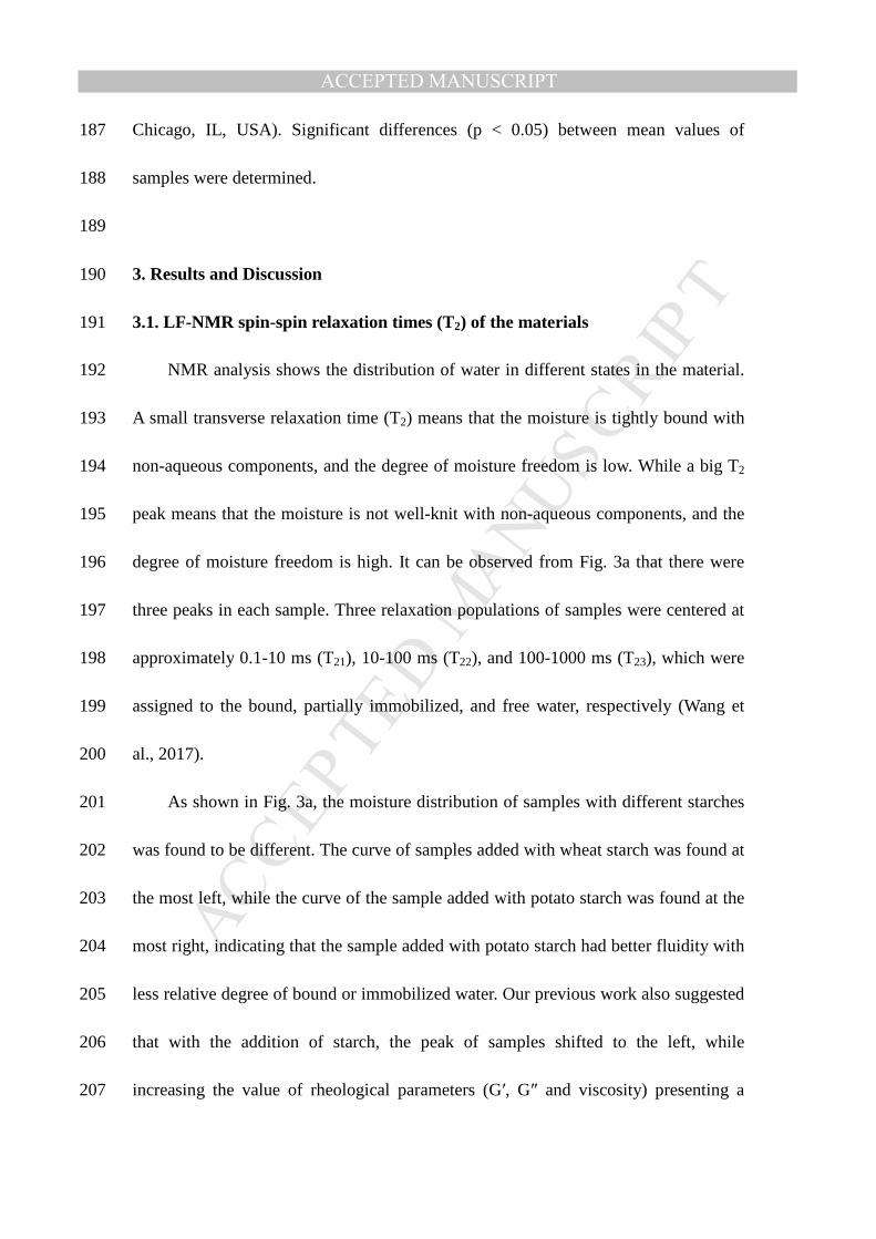
3.1. LF-NMR spin-spin relaxation times (T2) of the materials 191
NMR analysis shows the distribution of water in different states in the material. 192
A small transverse relaxation time (T2) means that the moisture is tightly bound with 193
non-aqueous components, and the degree of moisture freedom is low. While a big T2 194
peak means that the moisture is not well-knit with non-aqueous components, and the 195
degree of moisture freedom is high. It can be observed from Fig. 3a that there were 196
three peaks in each sample. Three relaxation populations of samples were centered at 197
approximately 0.1-10 ms (T21), 10-100 ms (T22), and 100-1000 ms (T23), which were 198
assigned to the bound, partially immobilized, and free water, respectively (Wang et 199
al., 2017). 200
As shown in Fig. 3a, the moisture distribution of samples with different starches 201
was found to be different. The curve of samples added with wheat starch was found at 202
the most left, while the curve of the sample added with potato starch was found at the 203
most right, indicating that the sample added with potato starch had better fluidity with 204
less relative degree of bound or immobilized water. Our previous work also suggested 205
that with the addition of starch, the peak of samples shifted to the left, while 206
increasing the value of rheological parameters (G′, G″ and viscosity) presenting a 207

MANUSCRIP
T
ACCEPTED
ACCEPTED MANUSCRIPT
better extrudate appearance (Yang et al., 2018). 208
Overall, from Fig. 3a, the free water and the bound water relative intensity were 209
found nearly zero, while the relative intensity of the partially immobilized water was 210
far greater. This suggested that the water state in the samples was mainly partially 211
immobilized water, thus, the samples had a certain fluidity and formability, which is 212
beneficial to the extrusion of 3D printing processes while maintaining the product 213
structure after printing. When the slurry revealed low fluidity with more solid-like 214
behavior, it was difficult extrude and the extruded filament was found to be broken 215
during deposition. Too much liquid-like slurries with high fluidity were also reported 216
to extrude larger amount of material extrusion than the set value affecting the 217
precision of geometry (Yang et al., 2018). It can be seen that the relative intensity of 218
free water of samples added with sweet potato starch is almost 0, indicating that the 219
internal water was mainly in the form of bound water and partially immobilized water, 220
which resulted in too much solid-behavior which may not be also suitable for the 221
extrusion. 222
3.2. Rheological behavior of the materials 223
Rheological properties are important indicators for evaluating the 3D printing 224
performance of materials (Derossi et al., 2017; Liu, Zhang, Bhandari, & Yang, 2017). 225
The viscosity of ideal food materials suitable for 3D printing should be low enough to 226
permit easy extrusion through a small nozzle and high enough to be cohesive without 227
deformation with the previous deposited layers (Lille, Nurmela, Nordlund, 228

MANUSCRIP
T
ACCEPTED
ACCEPTED MANUSCRIPT
Metsä-Kortelainen, & Sozer, 2017). Flow curves, as shown in Fig. 3b, illustrate the 229
dependence of apparent viscosities on shear rate. This suggested that lemon juice gels 230
added with different starches were all pseudoplastic fluids displaying shear-thinning 231
performances. The shear-thinning performance signifies that the chain of molecules or 232
particles in materials are affected by the shear stress between the layers when the flow 233
rate increases, thereby reducing the force between the molecules or particles 234
(Demirkesen, Mert, Sumnu, & Sahin, 2010). This shear-thinning performance was 235
reported beneficial for slurries to be extruded through the nozzle (Liu, Zhang, 236
Bhandari, & Yang, 2018). 237
The storage modulus (G') is a measure of the elastic solid-like behavior, which 238
reflects the mechanical strength of samples. The material with high mechanical 239
strength will show excellent self-supporting property after deposition and maintain a 240
stable shape after printing (Avery et al., 2014; Liu, Zhang, Bhandari, & Yang, 2017). 241
The loss modulus (G'') is the viscous response which is a ratio of stress to strain under 242
the dynamic oscillation frequency analysis. The loss tangent (tan δ= G''/G') is used as 243
a characteristic parameter to illustrate the different viscoelastic behavior (Fischer & 244
Windhab, 2011). A tan δ smaller than 1 means predominantly elastic property which 245
exhibiting solid characteristics. And, conversely, when tan δ is greater than 1, the 246
viscous property exhibits liquid characteristics (Winter & Mours, 1997). 247
Considering the viscoelastic properties of lemon juice gel, G' was found all 248
higher than G'' (Fig. 3c and Fig. 3d), which indicated that the materials formed elastic 249

MANUSCRIP
T
ACCEPTED
ACCEPTED MANUSCRIPT
gel or gel-like structures and the system of materials is in the state of elastic 250
dominance. Samples added with potato starch and wheat starch showed greater G' and 251
G'' than those added with corn starch and sweet potato starch. G' and G'' both 252
gradually increased with the increasing of oscillatory frequency, meanwhile tan δ was 253
found decreased at first, followed by an increase (Fig. 3e). However, tan δ for all 254
samples were found smaller than 1, indicating that all samples showed solid-like 255
behavior and poor fluidity. In addition, comparing the samples added with four kinds 256
of starches, it can be seen that the sample added with potato and corn starches had 257
smaller tan δ, showing that these two materials had stronger network structure and 258
more solid-like behavior. From the result of rheological tests of lemon-juice gel added 259
with four kinds of starches, the gel sample added with corn starch was found to have a 260
lower viscosity at high shear rates and relatively small tan δ. These results suggested 261
that the gel added with corn starch will be easy to be extruded by the syringe, which 262
offers a high shear rate at the exit (Fig. 4c), meanwhile presenting a good mechanical 263
properties (Liu, Zhang, Bhandari, & Wang, 2017; F. Yang et al., 2018; Zhang, Zhang, 264
Yang, & Chen, 2001). 265
3.3. Velocity distribution field analysis 266
The velocity field was reported to have a direct impact on the quality of the 267
material 3D printing, which is mainly reflected by the uniformity of the speed of the 268
material extrusion at the exit (Wang et al., 2017; Yang et al., 2018). 269
Fig. 4a and Fig. 4b show the distribution of velocity field at the channel and the 270
MANUSCRIP
T
ACCEPTED
ACCEPTED MANUSCRIPT
outlet, respectively, at the condition of material viscosity 8000 Pa·s, relaxation time 271
10 s, inlet volume flow rate 24 mm3/s and nozzle diameter 1.0 mm. It can be seen 272
intuitively that the material in the barrel part was in a low speed state (0.08 mm/s), 273
and the velocity showed no obvious change (Fig. 4a), while the material in the nozzle 274
was found to have a high speed. Meanwhile, the velocity of the material increased 275
obviously with a shrinkage of the nozzle diameter (the average speed of the materials 276
increased from 1.59 mm/s to 40.1 mm/s). Fig. 4b shows that on the same horizontal 277
section, the velocity of fluids decreased from the center to the surrounding. The 278
velocity at the center of nozzle was found to be maximum, while the nearer the wall, 279
the velocity of the material was lower. This was mainly due to the fact that a greater 280
influence of the friction of the material on the solid wall results in a considerable 281
velocity gradient along the normal to the wall (Rueda et al., 2016). 282
3.4. Shear rate field analysis 283
The viscosity of materials belonging to the pseudoplastic group of fluid presents 284
an alterable value with the change of shear rates, which will affect the quality of the 285
3D printing products. Fig. 4c and Fig. 4d show the distribution of the shear rate field 286
at the channel and outlet, respectively. In the barrel, the shear rate was found not 287
greatly changed, while the shear rate increases obviously with the decrease of the 288
diameter in the nozzle (Fig. 4c). The change of the shear rate in the flow channel was 289
shown to be small, while it turned to be larger near the wall (Fig. 4d). This 290
phenomenon indicated that the material was subjected to a larger shear force at the 291
MANUSCRIP
T
ACCEPTED
ACCEPTED MANUSCRIPT
wall, and also caused considerable velocity gradient along the normal direction of the 292
wall. Meanwhile, due to high shear rates at the exit of nozzle, the viscosity of the 293
material decreased indicating that the material was more easily extruded during 3D 294
printing process. 295
3.5. Pressure distribution field analysis 296
Pressure will have a significant impact on material extrusion process in a 297
continuous extrusion 3D printing process (Valkenaers, Jansen, Voet, Van Gysel, & 298
Ferraris, 2014). Fig. 4e shows the distribution of the pressure field at the channel and 299
the nozzle. As shown in Fig. 4e, the pressure on the same horizontal section showed to 300
be constant. Additionally, the pressure was stable in the barrel while it noticeable 301
changed in the nozzle. From the entrance to the exit of the nozzle, the pressure 302
gradually decreased, with no alteration observed, indicating that as long as the 303
material is under a sufficient pressure, the material flow can be stabile and 304
continuously extruded, meeting the requirements of 3D printing. 305
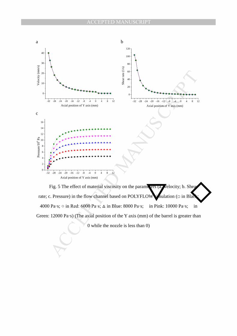
3.6. Effect of material viscosity on the parameters in the flow channel 306
From above sections, the viscosity of materials with different starches was found 307
to be different, which will affect the rheological parameters in the flow channel during 308
the 3D printing extrusion process. Thus, it is important to investigate effects of the 309
viscosity with changing values on the other parameters, such as shear rate and 310
pressure field. 311
The velocity field and shear rate field in the flow channel were found not to be 312

MANUSCRIP
T
ACCEPTED
ACCEPTED MANUSCRIPT
changed with the change of the viscosity of the material (Fig. 5a and Fig. 5b), which 313
mainly depended on the inlet volume flow rate. The pressure field changed obviously 314
with the change of material viscosities (Fig. 5c). With the decreasing of the viscosity 315
of materials, the overall pressure in the channel was found to be decreased. When the 316
viscosity decreased from 12000 Pa to 8000 Pa (by 30%), the pressure at the inlet of 317
the nozzle presented a reduction from 1.36×10⁷ to 9.10×10⁶ Pa and the decrease is 318
about 33%, which was found to be similar with the decrease of material viscosity. At a 319
constant viscosity, the pressure on the barrel varied little along the extrusion direction 320
of the material. Whereas at the nozzle, the greater the viscosity was, the faster the 321
pressure dropped, and the pressure tended to be the same at the outlet of the nozzle. 322
In addition, the pressure required for extruding materials should be at 323
comfortable values below the maximum pressure provided by the 3D printer. 324
Therefore, in the actual operation of 3D printing, the material can be adjusted to a 325
proper viscosity by proportionating formulation ensuring that the pressure in the 326
process is in a reasonable range. In present work, different starch additions provided 327
diverse viscosity increments. Among them, the lemon-juice gel added with corn starch 328
presented relatively low viscosities at high shear rates indicating that the gel added 329
with corn starch will flow smoothly at the nozzle and close to the exit than that added 330
with other starches. 331
3.7. Effect of inlet volume flow rate on the parameters in the flow channel 332
In food 3D printing processes, the material needs to be extruded under certain 333

MANUSCRIP
T
ACCEPTED
ACCEPTED MANUSCRIPT
pressure provided by the stepper motor of the 3D printer. In the syringe-based 334
extrusion printing process, the inlet volume flow rate is adjusted by changing the 335
speed of the piston, which is a key factor that affects the parameters of the flow path 336
and the 3D printing efficiency. Thus, this section investigated the effect of the inlet 337
volume flow rate at different values on the parameters in the flow channel. 338
The velocity, shear rate and pressure fields of the flow channel increased with the 339
increase of the entrance volume flow rate (Fig. 6a and Fig. 6b). With the increasing of 340
inlet volume flow rate from 20 mm3/s to 28 mm3/s (by 40%), the average velocity at 341
the outlet of the nozzle increased from 33.42 mm/s to 46.78 mm/s, while the average 342
shear rate increased from 86.44/s to 121.01/s (by 40%). This result was found to be 343
similar with the increase at the volume rate of the entrance (Fig. 6a and 6b). The 344
pressure at the inlet of the nozzle was found increased from 1.32×10⁶ to 1.85×10⁶ Pa, 345
and tended to be the same at the exit, indicating that the pressure gradually increased 346
in the flow channel (Fig. 6c). However, the trend of the rheological parameters in the 347
flow path was found to be similar, the rheological parameters in the barrel were 348
relatively stable, and the rheological parameters in the nozzle changed significantly. 349
3.8. Effect of nozzle diameter on the parameters in the flow channel 350
The diameter of the nozzle is reported as a critical parameter affecting the 351
printing time and printing precision of the printed object (Vaezi & Chua, 2011), and 352
has a certain influence on the rheological parameters in the flow channel. The nozzle 353
diameter was set as a variable to investigate its effects on the parameters in the flow 354
MANUSCRIP
T
ACCEPTED
ACCEPTED MANUSCRIPT
channel. Since the inlet volume flow rate was constant, no obvious difference was 355
found in the velocity and shear rate field in the flow channel (Fig. 7a and Fig. 7b). 356
However, a significant change was observed in the pressure field in the flow channel 357
(Fig. 7c). 358
With the nozzle diameter increased from 0.5 mm to 2.0 mm, the pressure at the 359
inlet was greatly reduced from 4.95×10⁷ Pa to 2.50×10⁶ Pa, indicating that the smaller 360
the diameter of the nozzle, the greater the pressure required for extruding the material. 361
Meanwhile, at the axial position of the Y axis, the larger the diameter of nozzles, the 362
greater values of the corresponding Y axis value when the pressure started to change 363
(-24 mm at 0.5 mm and -4 mm at 2.0 mm). It also showed that the smaller nozzle 364
diameter resulting in more high-pressure areas in the flow channel might lead to 365
material storing elastic energy and its release after extrusion causing an extrudate 366
swelling. Therefore, in the process of 3D printing, a suitable nozzle diameter, which 367
can provide a smooth extrusion below the maximum pressure that the equipment can 368
provide, can achieve high precision products. 369
3.9. Simulation of extrudate swell and adjustment of filling ratio 370
The swell effect of the extrudate is that the viscous elastic fluid will be subjected 371
to strong tensile deformation when it passes through the diameter contraction section, 372
and a part of the elastic potential energy is stored. The elastic potential energy of the 373
material will be released completely when the material leaves the nozzle, resulting in 374
a swelling of extrudate. The swell phenomenon of extrusion process is quantitatively 375
MANUSCRIP
T
ACCEPTED
ACCEPTED MANUSCRIPT
expressed by swell ratio, which is defined as the ratio of material diameter to nozzle 376
diameter after extrusion stabilization. On the basis of the previous model, the 377
simulation of the extrusion molding part is added. The results (Fig. 8A to Fig. 8E) 378
showed that the extrusion part presented a certain level of swelling. Fig. 8A-F showed 379
that the material after the extrusion showed to varying degrees of swelling at different 380
inlet volume flow rates. As the entrance volume flow rate was increased, the extrusion 381
swell ratio tended to decrease first and then increased. This is probably due to the fact 382
that the extrudate swell ratio will be influenced by the speed, shear rate, and pressure 383
at the same time. When the entrance volume flow rate was increased, the pressure in 384
the flow channel also increased, which will lead to the storage of more elastic 385
potential energy by the fluid. On the other hand, the shear rate of materials increased 386
correspondingly with the increase of entrance volume flow rate, the the shear-thinning 387
characteristic of gel resulted in the extrusion swell phenomenon reduced. When the 388
inlet volume flow rate was less than 24 mm3/s, the fluid was greatly affected by the 389
shear rate, which resulted in the extrusion swell ratio decreased with the inlet volume 390
flow rate. In contrast, when the inlet volume flow rate was greater than 24 mm3/s, the 391
fluid viscosity decreased, which was affected by the shear rate and the pressure. 392
Among two factors, the pressure affected more than by the shear rate. This 393
phenomenon resulted in a slight increase in the extrudate swell ratio when the 394
entrance volume flow rate was increased. However, due to the upper limit of the 395
elastic potential energy that the fluid can store, it can be predicted that the extrusion 396

MANUSCRIP
T
ACCEPTED
ACCEPTED MANUSCRIPT
swell ratio will eventually become flat. Overall, although the extrusion swell ratio 397
fluctuates with the change in the entrance material volume flow rate, the amplitude is 398
not large enough to influence the printing precision at different volume flow rates. 399
From above study on swelling phenomenon, it can be considered that the filling 400
ratio at 100% may not be appropriate in the printing process. When the filling ratio 401
was set at 100%, the material appeared partly bulging due to swelling effect. When 402
the filling ratio was reduced to 90%, the material could be completely and smoothly 403
paved with the whole plane. The results (Fig. 9) showed that the products obtained by 404
a filling ratio of 60%-80% presented obvious pores. Besides, the selected material 405
(lemon-juice gel added with corn starch) was found to have a certain flow capacity, so 406
the low filling ratio might lead to unsupported deformation conditions. Although there 407
might be little difference on the same layer of printed object, but when the number of 408
printing layers increases, the small change of each layer will cause the large 409
cumulative change. Therefore, it is appropriate to choose 90% filling ratio, which is 410
also consistent with the results obtained from the simulation. 411
412
4. Conclusions 413
The material suitable for 3D printing should have a certain range of rheological 414
parameters. Besides, it was found that the material viscosity and relaxation time, the 415
material inlet volume flow rate and the nozzle diameter affected the different 416
parameters in the flow channel in this study. The flow parameters were found stable in 417

MANUSCRIP
T
ACCEPTED
ACCEPTED MANUSCRIPT
the barrel section but varied greatly in the nozzle section. The velocity and shear 418
velocity fields were determined by the material inlet volume flow rate, and increased 419
with the increase of the volume flow rate. The pressure in the flow channel increased 420
in varying degrees with the increase of the material viscosity and the entrance volume 421
flow rate, and the decrease of relaxation time and the nozzle diameter. The change of 422
nozzle diameter was found to have the greatest influence on the pressure field. In 423
addition, the extruded material exhibited the phenomenon of swell. According to the 424
simulation calculation and the actual test, it was found that in the extrusion-based 3D 425
printing process the filling rate of 90% was suitable because of the swelling effect. 426
Although the parameter values obtained by the simulation have some deviations from 427
the actual values, this work provides a reference value for the optimization of 3D 428
printing food materials and the design of 3D printing extrusion flow channel. 429
430
Acknowledgments 431
The authors acknowledge the financial support from the 432
National Natural Science Foundation Program of China (No. 3187101297), China 433
State Key Laboratory of Food Science and Technology Innovation Project (Contract 434
No. SKLF-ZZA-201706),National First-class Discipline Program of Food Science 435
and Technology (No. JUFSTR20180205), Jiangsu Province Key Laboratory Project of 436
Advanced Food Manufacturing Equipment and Technology (No. FMZ201803), which 437
have enabled us to carry out this study. 438
MANUSCRIP
T
ACCEPTED
ACCEPTED MANUSCRIPT
439 440
References 441
Avery, M. P., Klein, S., Richardson, R., Bartlett, P., Adams, G., Dickin, F., & Simske, 442
S. (2014). The Rheology of Dense Colloidal Pastes Used in 3D-Printing. NIP 443
& Digital Fabrication Conference, 140-145. 444
Calvert, P. (2016). 3D printing of gels with living photosynthetic algae. Mrs 445
Advances, 1, 2569-2572. 446
Chen, T., Lin, H., Zhao, H., Chen, X., Wu, T., Li, G., . . . Xie, L. (2017). Agglomerate 447
size evolution in modular twin-screw extruder: Modeling and validation with 448
CaCO3/LLDPE compounding experiments. Journal of Applied Polymer 449
Science, 134, 45535. 450
Chen, Z. (2016). Research on the Impact of 3D Printing on the International Supply 451
Chain. Advances in Materials Science and Engineering, 2016, 1-16. 452
Demirkesen, I., Mert, B., Sumnu, G., & Sahin, S. (2010). Rheological properties of 453
gluten-free bread formulations. Journal of Food Engineering, 96, 295-303. 454
Derossi, A., Caporizzi, R., Azzollini, D., & Severini, C. (2017). Application of 3D 455
printing for customized food. A case on the development of a fruit-based snack 456
for children. Journal of Food Engineering, 220, 65-75. 457
Filali, A., Khezzar, L., Siginer, D., & Nemouchi, Z. (2012). Graetz problem with 458
non-linear viscoelastic fluids in non-circular tubes. International Journal of 459
Thermal Sciences, 61, 50-60. 460

MANUSCRIP
T
ACCEPTED
ACCEPTED MANUSCRIPT
Fischer, P., & Windhab, E. J. (2011). Rheology of food materials. Current Opinion in 461
Colloid & Interface Science, 16, 36-40. 462
Godoi, F. C., Prakash, S., & Bhandari, B. R. (2016). 3d printing technologies applied 463
for food design: Status and prospects. Journal of Food Engineering, 179, 464
44-54. 465
Gray, N. (Producer). (2010, 23-Dec-2010). Looking to the future: Creating novel 466
foods using 3D printing. Retrieved from 467
http://www.foodnavigator.com/Science-Nutrition/Looking-to-the-future-Creati468
ngnovel-foods-using-3D-printing 469
Hao, L., Mellor, S., Seaman, O., Henderson, J., Sewell, N., & Sloan, M. (2010). 470
Material characterisation and process development for chocolate additive layer 471
manufacturing. Virtual & Physical Prototyping, 5, 57-64. 472
Jia, F., Wang, X., Mustafee, N., & Hao, L. (2016). Investigating the feasibility of 473
supply chain-centric business models in 3D chocolate printing: A simulation 474
study. Technological Forecasting & Social Change, 102, 202-213. 475
Lanaro, M., Forrestal, D. P., Scheurer, S., Slinger, D. J., Liao, S., Powell, S. K., & 476
Woodruff, M. A. (2017). 3D printing complex chocolate objects: Platform 477
design, optimization and evaluation. Journal of Food Engineering, 215, 13-22. 478
Le Tohic, C. L., O'Sullivan, J. J., Drapala, K. P., Chartrin, V., Chan, T., Morrison, A. 479
P., . . . Kelly, A. L. (2017). Effect of 3D printing on the structure and textural 480
properties of processed cheese. Journal of Food Engineering, 220, 56-64. 481
MANUSCRIP
T
ACCEPTED
ACCEPTED MANUSCRIPT
Lee, J. Y., Jia, A., & Chua, C. K. (2017). Fundamentals and applications of 3D 482
printing for novel materials. Applied Materials Today, 7, 120–133. 483
Li, P., Mellor, S., Griffin, J., Waelde, C., Hao, L., & Everson, R. (2014). Intellectual 484
property and 3D printing: a case study on 3D chocolate printing. Journal of 485
Intellectual Property Law & Practice, 9, 322-332. 486
Lille, M., Nurmela, A., Nordlund, E., Metsä-Kortelainen, S., & Sozer, N. (2017). 487
Applicability of protein and fiber-rich food materials in extrusion-based 3D 488
printing. Journal of Food Engineering, 220, 20-27. 489
Lille, M., Nurmela, A., Nordlund, E., Metsä-Kortelainen, S., & Sozer, N. (2018). 490
Applicability of protein and fiber-rich food materials in extrusion-based 3D 491
printing. Journal of Food Engineering, 220, 20-27. 492
Liu, Z., Bhandari, B., Prakash, S., & Zhang, M. (2018). Creation of internal structure 493
of mashed potato construct by 3D printing and its textural properties. Food 494
Research International, 111, 534-543. 495
Liu, Z., Zhang, M., Bhandari, B., & Wang, Y. (2017). 3D printing: Printing precision 496
and application in food sector. Trends in Food Science & Technology, 69, 497
83-94. 498
Liu, Z., Zhang, M., Bhandari, B., & Yang, C. (2017). Impact of rheological properties 499
of mashed potatoes on 3D printing. Journal of Food Engineering, 220, 76-82. 500
Liu, Z., Zhang, M., Bhandari, B., & Yang, C. (2018). Impact of rheological properties 501
of mashed potatoes on 3D printing. Journal of Food Engineering, 220, 76-82. 502

MANUSCRIP
T
ACCEPTED
ACCEPTED MANUSCRIPT
Rueda, M. M., Auscher, M. C., Fulchiron, R., Périé, T., Martin, G., Sonntag, P., & 503
Cassagnau, P. (2016). Rheology and Applications of Highly Filled Polymers: 504
A review of current understanding. Progress in Polymer Science, 66, 22-53. 505
Sun, J., Zhou, W., Huang, D., Fuh, J. Y., & Hong, G. S. (2015). An overview of 3D 506
printing technologies for food fabrication. Food and Bioprocess Technology, 8, 507
1605-1615. 508
Sun, J., Zhou, W., Yan, L., Huang, D., & Lin, L.-y. (2018). Extrusion-based food 509
printing for digitalized food design and nutrition control. Journal of Food 510
Engineering, 220, 1-11. 511
Vaezi, M., & Chua, C. K. (2011). Effects of layer thickness and binder saturation level 512
parameters on 3D printing process. International Journal of Advanced 513
Manufacturing Technology, 53, 275-284. 514
Valkenaers, H., Jansen, D., Voet, A., Van Gysel, A., & Ferraris, E. (2014). Additive 515
manufacturing for concrete: a 3D printing principle. Paper presented at the 516
euspen International Conference edition:2014, Dubrovnik. 517
Vancauwenberghe, V., Katalagarianakis, L., Wang, Z., Meerts, M., Hertog, M., 518
Verboven, P., . . . Nicolaï, B. (2017). Pectin based food-ink formulations for 519
3-D printing of customizable porous food simulants. Innovative Food Science 520
& Emerging Technologies, 42, 138-150. 521
Wang, L., Zhang, M., Bhandari, B., & Yang, C. (2017). Investigation on fish surimi 522
gel as promising food material for 3D printing. Journal of Food Engineering, 523
MANUSCRIP
T
ACCEPTED
ACCEPTED MANUSCRIPT
220, 101-108. 524
Wilczyński, K., Laczyński, B., & Czaplarski, A. (1998). Modeling of generalized flow 525
of newtonian fluids by the POLYFLOW system. Polimery, 43, 115-120. 526
Wilczyński, K., & Tyszkiewicz, A. (1996). Computer modelling of plastics processing 527
methods with the POLYFLOW system. Polimery, 41, 107-112. 528
Winter, H. H., & Mours, M. (1997). Rheology of Polymers Near Liquid-Solid 529
Transitions. Berlin Heidelberg: Springer. 530
Yang, F., Zhang, M., Bhandari, B., & Liu, Y. (2018). Investigation on lemon juice gel 531
as food material for 3D printing and optimization of printing parameters. LWT 532
- Food Science and Technology, 87, 67-76. 533
Yang, J., Wu, L., & Liu, J. (2001). U.S. Patent No. 534
Zhang, B., Zhang, Y., Yang, L., & Chen, J. (2001). Study on the crystalline structure 535
and property of corn, cassava and potato starch granules. Food Science, 22, 536
11-14. 537
538

MANUSCRIP
T
ACCEPTED
ACCEPTED MANUSCRIPT
Figure Captions
Fig. 1 3D model of charging barrel (a-e) and meshing of charging barrel model (f)
Fig. 2 Schematic diagram of the 3D printer setup used in this study (Liu, Bhandari, et
al., 2018).
Fig. 3 NMR signal (T2) (a) and rheological behavior (b. apparent viscosity, c. G’, d.
G” and e. tanδ) of the lemon juice gel added with different starches (□ in Black:
Potato starch; ○ in Red: Corn starch; △ in Blue: Sweet potato starch;
▽ in Pink:
Wheat starch)
Fig. 4 Velocity field (a: Channel section; b: Outlet section), shear rate field (c:
Channel section; d: Outlet section) and pressure field (e) in the channel of
POLYFLOW simulation
Fig. 5 The effect of material viscosity on the parameters (a. Velocity; b. Shear rate; c.
Pressure) in the flow channel based on POLYFLOW simulation (□ in Black:
4000 Pa·s; ○ in Red: 6000 Pa·s; △ in Blue: 8000 Pa·s;
▽ in Pink: 10000 Pa·s;
◇
in Green: 12000 Pa·s) (The axial position of the Y axis (mm) of the barrel is
greater than 0 while the nozzle is less than 0)
Fig. 6 The effect of inlet volume flow rate on the parameters (a. Velocity; b. Shear rate;
c. Pressure) in the flow channel based on POLYFLOW simulation (□ in Black:
20 mm3/s; ○ in Red: 24 mm3/s; △ in Blue: 28 mm3/s) (The axial position of the Y
axis (mm) of the barrel is greater than 0 while the nozzle is less than 0)
Fig. 7 The effect of nozzle diameter on the parameters (a. Velocity; b. Shear rate; c.

MANUSCRIP
T
ACCEPTED
ACCEPTED MANUSCRIPT
Pressure) in the flow channel based on POLYFLOW simulation (□ in Black: 0.5
mm; ○ in Red: 1.0 mm; △ in Blue: 1.5 mm;
▽ in Pink: 2 mm) (The axial position
of the Y axis (mm) of the barrel is greater than 0 while the nozzle is less than 0)
Fig. 8 Simulation diagram (A: 16 mm3/s, B: 20 mm3/s, C: 24 mm3/s, D: 28 mm3/s,
E:32 mm3/s) and broken line graph (F) of material extrusion swell at different
entrance volume rates
Fig. 9 The effect of filling rate on the quality of 3D printing (A:60%,B:70%,C:
80%,D:90%,E:100%)

MANUSCRIP
T
ACCEPTED
ACCEPTED MANUSCRIPT
Fig. 1 3D model of charging barrel (a-e) and meshing of charging barrel model (f)

MANUSCRIP
T
ACCEPTED
ACCEPTED MANUSCRIPT
Fig. 2 schematic diagram of the 3D printer setup used in this study (Liu, Bhandari, et al., 2018).

MANUSCRIP
T
ACCEPTED
ACCEPTED MANUSCRIPT
a b
0.1 1 10 100 1000 10000-50
0
50
100
150
200
250
300
350
400
T2(ms)
Rel
ativ
e in
ten
sity
)
0.01 0.1 1 10 100
10
100
1000
10000
Vis
cosi
ty (
Pa
·s)
Shear rate (1/s)
c d
0.1 1 10 1000
1000
2000
3000
4000
5000
G' (
Pa)
ω (rad/s)
0.1 1 10 1000
400
800
1200
1600
2000
G''
(Pa)
ω (rad/s)
e
0.1 1 10 1000.15
0.20
0.25
0.30
0.35
0.40
ω (rad/s)
tanδ
Fig. 3 NMR signal (T2) (a) and rheological behavior (b. apparent viscosity, c. G’, d. G” and e. tan δ) of the lemon juice gel added with different starches (□ in Black:
Potato starch; ○ in Red: Corn starch; △ in Blue: Sweet potato starch;
▽ in Pink: Wheat
starch)

MANUSCRIP
T
ACCEPTED
ACCEPTED MANUSCRIPT
a b
c d
e
Fig. 4 Velocity field (a: Channel section; b: Outlet section), shear rate field (c:
Channel section; d: Outlet section) and pressure field (e) in the channel of
POLYFLOW simulation
MANUSCRIP
T
ACCEPTED
ACCEPTED MANUSCRIPT
a b
-32 -28 -24 -20 -16 -12 -8 -4 0 4 8 12
0
10
20
30
40
Ve
loci
ty (
mm
/s)
Axial position of Y axis (mm) -32 -28 -24 -20 -16 -12 -8 -4 0 4 8 12
0
20
40
60
80
100
120
Sh
ear
rate
(1
/s)
Axial position of Y axis (mm)
c
-32 -28 -24 -20 -16 -12 -8 -4 0 4 8 120
2
4
6
8
10
12
14
16
Pre
ssu
re/1
06 Pa
Axial position of Y axis (mm)
Fig. 5 The effect of material viscosity on the parameters (a. Velocity; b. Shear
rate; c. Pressure) in the flow channel based on POLYFLOW simulation (□ in Black:
4000 Pa·s; ○ in Red: 6000 Pa·s; △ in Blue: 8000 Pa·s;
▽ in Pink: 10000 Pa·s;
◇ in
Green: 12000 Pa·s) (The axial position of the Y axis (mm) of the barrel is greater than
0 while the nozzle is less than 0)

MANUSCRIP
T
ACCEPTED
ACCEPTED MANUSCRIPT
a b
-32 -28 -24 -20 -16 -12 -8 -4 0 4 8 12
0
10
20
30
40
50
Ve
loci
ty (
mm
/s)
Axial position of Y axis (mm) -32 -28 -24 -20 -16 -12 -8 -4 0 4 8 12
0
20
40
60
80
100
120
140
Sh
ear
rate
(1
/s)
Axial position of Y axis (mm)
c
-32 -28 -24 -20 -16 -12 -8 -4 0 4 8 120
2
4
6
8
10
12
Pre
ssur
e/1
06 Pa
Axial position of Y axis (mm)
Fig. 6 The effect of entrance volume rate on the parameters (a. Velocity; b. Shear
rate; c. Pressure) in the flow channel based on POLYFLOW simulation (□ in Black:
20 mm3/s; ○ in Red: 24 mm3/s; △ in Blue: 28 mm3/s) (The axial position of the Y axis
(mm) of the barrel is greater than 0 while the nozzle is less than 0)

MANUSCRIP
T
ACCEPTED
ACCEPTED MANUSCRIPT
a b
-36 -32 -28 -24 -20 -16 -12 -8 -4 0 4 8 12-20
0
20
40
60
80
100
120
140
160
180
Ve
loci
ty (
mm
/s)
Axial position of Y axis (mm) -36 -32 -28 -24 -20 -16 -12 -8 -4 0 4 8 12
0
200
400
600
800
1000
She
ar
rate
(1
/s)
Axial position of Y axis (mm)
c
-36 -32 -28 -24 -20 -16 -12 -8 -4 0 4 8 1210-1
100
101
Pre
ssu
re (
MP
a)
Axial position of Y axis (mm)
0.5 mm 1.0 mm 1.5 mm 2.0 mm
Fig. 7 The effect of nozzle diameter on the parameters (a. Velocity; b. Shear rate;
c. Pressure) in the flow channel based on POLYFLOW simulation (□ in Black: 0.5
mm; ○ in Red: 1.0 mm; △ in Blue: 1.5 mm;
▽ in Pink: 2 mm) (The axial position of
the Y axis (mm) of the barrel is greater than 0 while the nozzle is less than 0)

MANUSCRIP
T
ACCEPTED
ACCEPTED MANUSCRIPT
Fig. 8 Simulation diagram (A: 16 mm3/s, B: 20 mm3/s, C: 24 mm3/s, D: 28
mm3/s, E:32 mm3/s) and broken line graph (F) of material extrusion swell at different
entrance volume rates

MANUSCRIP
T
ACCEPTED
ACCEPTED MANUSCRIPT
Fig. 9 The effect of filling rate on the quality of 3D printing
(A:60%,B:70%,C:80%,D:90%,E:100%)

MANUSCRIP
T
ACCEPTED
ACCEPTED MANUSCRIPT
Highlights:
� Moisture properties of lemon juice gels were investigated with different
starches.
� Rheological properties of lemon juice gels were investigated with different
starches.
� Using computer simulation to study the fluid characteristics during 3D
printing.
� Effects of different process parameters on fluid characteristics were
simulated.


