
lecture 10
Dr. Ali Karimpour (Presented by: Ms. Helmi, Mr Talebi and Ms. Faal) Jun 2015
InstrumentationAli Karimpour
Associate Professor
Ferdowsi University of Mashhad
In The Name of Allah
Dr. Ali Karimpour Feb 2015

lecture 10
Dr. Ali Karimpour (Presented by: Ms. Helmi, Mr Talebi and Ms. Faal) Jun 2015
2
Actuators
Topics to be covered include:
Hydraulic actuatorsPresented by: Ms. Fatemeh Helmi
Pneumatic actuatorsPresented by: Mr. Javad Talebi
Piezoelectric sensor/actuatorPresented by: Ms. Zahra faal
Hydraulic actuators

lecture 10
Dr. Ali Karimpour (Presented by: Ms. Helmi, Mr Talebi and Ms. Faal) Jun 2015
Hydraulic Actuator
3
A hydraulic actuator is a device for converting
hydraulic power into mechanical power.
There are two types of actuators:
Rotary
Linear

lecture 10
Dr. Ali Karimpour (Presented by: Ms. Helmi, Mr Talebi and Ms. Faal) Jun 2015
4
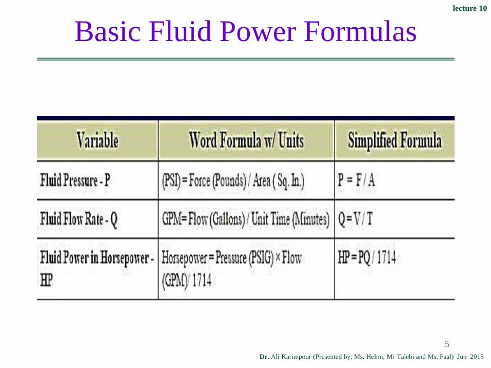
Hydraulic Actuator Principle
Pascal’s Law
Pressure applied to a confined fluid at any point
is transmitted undiminished and equally
throughout the fluid in all directions and acts
upon every part of the confining vessel at right
angles to its interior surfaces.
Amplification of Force
Since pressure P applied on an area A gives rise
to a force F, so : F = P×A
lecture 10
Dr. Ali Karimpour (Presented by: Ms. Helmi, Mr Talebi and Ms. Faal) Jun 2015
5
Basic Fluid Power Formulas

lecture 10
Dr. Ali Karimpour (Presented by: Ms. Helmi, Mr Talebi and Ms. Faal) Jun 2015
Actuator Formulas
6

lecture 10
Dr. Ali Karimpour (Presented by: Ms. Helmi, Mr Talebi and Ms. Faal) Jun 2015
Types of Actuators
7
Rotary actuators are called hydraulic
motors, while linear actuators are called
hydraulic cylinders.

lecture 10
Dr. Ali Karimpour (Presented by: Ms. Helmi, Mr Talebi and Ms. Faal) Jun 2015
8
Linear Actuators
Hydraulic cylinders are linear actuators,
that is, they produce straight-line motion
and/or force.
There are two types of hydraulic cylinders:
♦ Single acting
♦ Double acting

lecture 10
Dr. Ali Karimpour (Presented by: Ms. Helmi, Mr Talebi and Ms. Faal) Jun 2015
9
The double-acting cylinder is operated by hydraulic fluid in both
directions and is capable of a power stroke either way.
Single and Double Acting Cylinder
In single-acting cylinder the control pressure
is applied to one side of the piston.

lecture 10
Dr. Ali Karimpour (Presented by: Ms. Helmi, Mr Talebi and Ms. Faal) Jun 2015
10
Applications of Hydraulic Cylinders Actuators
Mining industry
Construction machinery
Defense technology
Automotive engineering
Mechanical engineering
Textile industries
Railways
Power plants
Agricultural machinery

lecture 10
Dr. Ali Karimpour (Presented by: Ms. Helmi, Mr Talebi and Ms. Faal) Jun 2015
11
Different Types of Hydraulic Motors
Hydraulic Gear Motors
Hydraulic Vane Motors
Hydraulic Piston Motors♦ Axial Piston Motor
♦ Radial Piston Motor
Limited Rotation Hydraulic Actuators♦ Vane type
♦ Rack and pinion type
♦ Helical type
lecture 10
Dr. Ali Karimpour (Presented by: Ms. Helmi, Mr Talebi and Ms. Faal) Jun 2015
Hydraulic Gear Motors
Gear motors are high speed motors. If your
operation requires a lower speed, you can reduce
the output speed of the shaft by using gears.
The operating pressure of gear motors is usually
quite low: between 150 and 250 bar. Modern gear
motors, however, are capable of operating at
continuous pressures of up to 250 bar.

lecture 10
Dr. Ali Karimpour (Presented by: Ms. Helmi, Mr Talebi and Ms. Faal) Jun 2015
Hydraulic Gear Motors
Key features of gear motors:
Low weight and size
Relatively high pressures
Low cost
Wide range of speeds
Wide temperature range
Simple and durable design
Wide viscosity rangeA major drawback of gear
motors is that they
produce a large amount of
noise.

lecture 10
Dr. Ali Karimpour (Presented by: Ms. Helmi, Mr Talebi and Ms. Faal) Jun 2015
14
Typical parameters are:
Displacement volume: 3 to 100 cc
Maximum pressure: up to 250 bar
Range of speeds: 500 to 4,000 rpm
Maximum torque: up to 400 Nm
Hydraulic Gear Motors

lecture 10
Dr. Ali Karimpour (Presented by: Ms. Helmi, Mr Talebi and Ms. Faal) Jun 2015
15
Hydraulic Vane Motors
The vane motor rotates as hydraulic fluid at high
pressure flows through the motor to the outlet.

lecture 10
Dr. Ali Karimpour (Presented by: Ms. Helmi, Mr Talebi and Ms. Faal) Jun 2015
16
Hydraulic Vane Motors
Key features of hydraulic vane motors are:
Low noise level
Low flow pulsation
High torque at low speeds
Simple design
Easy serviceability
Vertical installation easily

lecture 10
Dr. Ali Karimpour (Presented by: Ms. Helmi, Mr Talebi and Ms. Faal) Jun 2015
17
Hydraulic Vane Motors
Typical parameters:
Displacement volume: 9 to 214 cc
Maximum pressure: up to 230 bar
Range of speeds: 100 to 2,500 rpm
Maximum torque: up to 650 Nm

lecture 10
Dr. Ali Karimpour (Presented by: Ms. Helmi, Mr Talebi and Ms. Faal) Jun 2015
18
There are two types of piston motors:
Radial piston type arranged radially in a cylinder block.
Axial piston type arranged parallel to each other and to
cylinder block.
Hydraulic Axial Piston Motors

lecture 10
Dr. Ali Karimpour (Presented by: Ms. Helmi, Mr Talebi and Ms. Faal) Jun 2015
19
Hydraulic Axial Piston Motors
Axial piston motors work with a bent axis design or
swash plate principle.
In the bent axis design, pistons move up and down
within the cylinder block bores. This motion is
converted into rotary movement via the piston ball
joint at the drive flange.
In the swash plate design, pistons move up and down
within the cylinder block and turn it, which then turns
the drive shaft via the connected cotter pin.

lecture 10
Dr. Ali Karimpour (Presented by: Ms. Helmi, Mr Talebi and Ms. Faal) Jun 2015
20
Hydraulic Radial Piston Motors
Typical parameters of axial piston motors:
Displacement volume: 10 to 1,000 cc (multi-
stroke up to 1,500 cc)
Maximum pressure: up to 450 bar
Range of speeds: 500 to 11,000 rpm
Maximum torque: up to 10,750 Nm

lecture 10
Dr. Ali Karimpour (Presented by: Ms. Helmi, Mr Talebi and Ms. Faal) Jun 2015
21
Hydraulic Radial Piston Motors

lecture 10
Dr. Ali Karimpour (Presented by: Ms. Helmi, Mr Talebi and Ms. Faal) Jun 2015
22
Hydraulic Radial Piston Motors
Radial Piston motors include a rotating
cylinder containing equally spaced radial
pistons arranged radial around the cylinder
center line.

lecture 10
Dr. Ali Karimpour (Presented by: Ms. Helmi, Mr Talebi and Ms. Faal) Jun 2015
23
Hydraulic Radial Piston Motors
Typical parameters of radial piston motors:
Displacement volume: 10 to 8,500 cc
Maximum pressure: up to 300 bar
Range of speeds: 0.5 to 2,000 rpm
Maximum torque: up to 32,000 Nm

lecture 10
Dr. Ali Karimpour (Presented by: Ms. Helmi, Mr Talebi and Ms. Faal) Jun 2015
Limited Rotation Hydraulic Actuators
A hydraulic motor is a mechanical actuators that
converts hydraulic pressure and flow into torque
and angular displacement (rotation).
The most common types of rotary actuators are:
Vane
rack-and-pinion
helica

lecture 10
Dr. Ali Karimpour (Presented by: Ms. Helmi, Mr Talebi and Ms. Faal) Jun 2015
25
Vane Actuator
A pressure difference between the two parts causes the
vane to rotate .
The maximum rotation of vane rotary actuators is
limited to approximately 280° in a single-vane model
and approximately 100° in the double-vane
configuration.

lecture 10
Dr. Ali Karimpour (Presented by: Ms. Helmi, Mr Talebi and Ms. Faal) Jun 2015
26
Vane Actuator
Hydraulic Rotary vane actuators have many
applications: Automotive assembly and testing
Construction equipment
Industrial automation
Maximum output torque of single-vane
actuator is 40 KNm and maximum output
torque of double-vane actuator is 80 KNm .

lecture 10
Dr. Ali Karimpour (Presented by: Ms. Helmi, Mr Talebi and Ms. Faal) Jun 2015
Rack-and-Pinion Actuator
Rack and pinion actuators consist of a housing to
support a pinion which is driven by a rack with
cylinder pistons on the ends.
27

lecture 10
Dr. Ali Karimpour (Presented by: Ms. Helmi, Mr Talebi and Ms. Faal) Jun 2015
Rack-and-Pinion Actuator
Typical rotary actuator applications are for
working pressures of up to 210 bar for
hydraulic actuators, with rotations of 90°,
180° or 360°.
28

lecture 10
Dr. Ali Karimpour (Presented by: Ms. Helmi, Mr Talebi and Ms. Faal) Jun 2015
Helical Actuator
In the Helical Spline compact actuators (HP)
the piston thrust is converted into torque
through a constant pitch helical coupling.
These actuators act like the Rack and Pinion
ones providing a linear torque curve due to the
constant gear ratio
29

lecture 10
Dr. Ali Karimpour (Presented by: Ms. Helmi, Mr Talebi and Ms. Faal) Jun 2015
Helical Actuator
The range of output torque is 0 to 15000 lb-in and
working pressure is 0 to 300 psi with rotations up
to 360°.
30

lecture 10
Dr. Ali Karimpour (Presented by: Ms. Helmi, Mr Talebi and Ms. Faal) Jun 2015
31
Actuators
Topics to be covered include:
Hydraulic actuatorsPresented by: Ms. Fatemeh Helmi
Pneumatic actuatorsPresented by: Mr. Javad Talebi
Piezoelectric sensor/actuatorPresented by: Ms. Zahra faal

lecture 10
Dr. Ali Karimpour (Presented by: Ms. Helmi, Mr Talebi and Ms. Faal) Jun 2015
Hydraulic Actuator
32
A hydraulic actuator is a device for converting
hydraulic power into mechanical power.
There are two types of actuators:
Rotary
Linear

lecture 10
Dr. Ali Karimpour (Presented by: Ms. Helmi, Mr Talebi and Ms. Faal) Jun 2015
33
Pneumatic Actuators
A pneumatic actuator is a device for converting
pneumatic power into mechanical power.
There are two types of actuators:
Rotary
Linear

lecture 10
Dr. Ali Karimpour (Presented by: Ms. Helmi, Mr Talebi and Ms. Faal) Jun 2015
Advantages of Pneumatic Actuators
Simplicity of realization relatively to small back and forth motions
Sophisticated transfer mechanisms are not required
Low cost
Good long term(reproducibility)
34
High speed of moving;
Ease at reversion movements;
High reliability of work;
Explosion and fire safety;
Good precision;

lecture 10
Dr. Ali Karimpour (Presented by: Ms. Helmi, Mr Talebi and Ms. Faal) Jun 2015
Disadvantages of Pneumatic Actuators
Compressibility of the air
Impossibility to receive uniform and constant speed of the
working bodies movement
Difficulties in performance at slow speed
Limited conditions - use of compressed air is beneficial up
to the definite values of pressure
Compressed air requires good preparation
35

lecture 10
Dr. Ali Karimpour (Presented by: Ms. Helmi, Mr Talebi and Ms. Faal) Jun 2015
Pneumatic linear actuators
Pneumatic linear actuators or pneumatic cylinders, are
similar to hydraulic actuators except that they use
compressed gas to generate force instead of a liquid.
36

lecture 10
Dr. Ali Karimpour (Presented by: Ms. Helmi, Mr Talebi and Ms. Faal) Jun 2015
Rotary Actuators
Rotary actuators : A rotary actuator is an actuator that
produces a rotary motion or torque from pneumatic signal.
37

lecture 10
Dr. Ali Karimpour (Presented by: Ms. Helmi, Mr Talebi and Ms. Faal) Jun 2015
Pneumatic Artificial Muscles
The Air Muscle is an extraordinary actuator that is
small, light, simple and 'friendly'. It is soft, is easily
controllable and exceptionally powerful.
38

lecture 10
Dr. Ali Karimpour (Presented by: Ms. Helmi, Mr Talebi and Ms. Faal) Jun 2015
Pneumatic Artificial Muscles
Lightweight: Air Muscles weigh as little as 10 grams -particularly
useful for weight-critical applications.
Lower Cost: Air Muscles are cheaper to buy and install than other
actuators and pneumatic cylinders.
Smooth: Air Muscles have an immediate response. This results in smooth
and natural movement.
39
Flexible: Air Muscles can be operated when twisted axially, bent round
a corner, and need no precise aligning.
Powerful: Air Muscles produce an incredible force especially
when fully stretched.
Compliant: Being a soft actuator, Air Muscles systems are
inherently compliant.

lecture 10
Dr. Ali Karimpour (Presented by: Ms. Helmi, Mr Talebi and Ms. Faal) Jun 2015
Pneumatic Artificial Muscles
40
lecture 10
Dr. Ali Karimpour (Presented by: Ms. Helmi, Mr Talebi and Ms. Faal) Jun 2015
41
Actuators
Topics to be covered include:
Hydraulic actuatorsPresented by: Ms. Fatemeh Helmi
Pneumatic actuatorsPresented by: Mr. Javad Talebi
Piezoelectric sensor/actuatorPresented by: Ms. Zahra faal

lecture 10
Dr. Ali Karimpour (Presented by: Ms. Helmi, Mr Talebi and Ms. Faal) Jun 2015
Piezoelectric sensor/actuator
A brief history of piezo effect.
Introducing of piezo electric effect and
inverse piezo effect.
Different shapes of Dura act
Working Principle.
Technology
Working Diagram
42
Piezoelectric

lecture 10
Dr. Ali Karimpour (Presented by: Ms. Helmi, Mr Talebi and Ms. Faal) Jun 2015
Piezoelectric Sensor/Actuator(Dura act patch
transducer)
Parameters for Bender Actuators
Power Requirements
Fields of Application
43

lecture 10
Dr. Ali Karimpour (Presented by: Ms. Helmi, Mr Talebi and Ms. Faal) Jun 2015
History of Piezo Effect
The term piezo is derived from the Greek word for
pressure.
In 1880 Jacques and Pierre Curie discovered that
an electric potential could be generated by
applying pressure to quartz crystals; they named
this phenomenon the piezoelectric effect.
Later they ascertained that when exposed to an
electric potential, piezoelectric materials change
shape.
This they named the inverse piezoelectric effect.
44
.

lecture 10
Dr. Ali Karimpour (Presented by: Ms. Helmi, Mr Talebi and Ms. Faal) Jun 2015
45
Pressure(changing shape) electric potential :"Piezo
electric effect" use for sensor
Electric potential to piezoelectric material changing
shape " inverse Piezo electric effect" for actuator
Introducing of piezoelectric effect and inverse
piezo effect

lecture 10
Dr. Ali Karimpour (Presented by: Ms. Helmi, Mr Talebi and Ms. Faal) Jun 2015
Introduction of Dura act patch transducer
46
Functionality as actuator and sensor component
Nominal operating voltage from 100 up to 1000 V,
depending on the active layer height ..
Power generation for self-sufficient systems possible
up to the milli watt range Can also be applied to curved
surfaces

lecture 10
Dr. Ali Karimpour (Presented by: Ms. Helmi, Mr Talebi and Ms. Faal) Jun 2015
Different Shapes of Dura Act
47
Dimensions and Geometric
Shapes
DuraAct patch transducers can be
adapted individually to each
application. This includes a free
selection of dimensions and
geometric shape.The height of the
piezo ceramic determines the
bending properties. Depending on
the operating temperature, various
piezoceramic materials can be
used.

lecture 10
Dr. Ali Karimpour (Presented by: Ms. Helmi, Mr Talebi and Ms. Faal) Jun 2015
Different Shapes of Dura Act
48
Arrays
To monitor larger areas, several DuraAct transducers
can be incorporated in one single laminate.
Electrical contacting of the piezo ceramics is
established jointly or individually. If a single
DuraAct element is used both as actuator and sensor,
the piezo ceramic can be built in several layers.

lecture 10
Dr. Ali Karimpour (Presented by: Ms. Helmi, Mr Talebi and Ms. Faal) Jun 2015
Different Shapes of Dura Act
49
Special Electronics for Sensor Applications
For sensor data processing, controlling the DuraAct
actuator or for harvesting energy and structural health
monitoring, electronic modules can be connected
close to the transducer. Contact is established using
solder pins or miniature plugs.

lecture 10
Dr. Ali Karimpour (Presented by: Ms. Helmi, Mr Talebi and Ms. Faal) Jun 2015
Different Shapes of Dura Act
50

lecture 10
Dr. Ali Karimpour (Presented by: Ms. Helmi, Mr Talebi and Ms. Faal) Jun 2015
Working Principle of Dura Act
51
The piezoceramic plates in DuraAct patch transducers resemble
a capacitor. The ceramic acts as a dielectric between its
metallized surfaces. When voltage is applied, an electric field is
created inside the ceramic. The field causes a uniform lateral
contraction of the ceramic perpendicular to the direction of the
electric field. This behavior is called the transverse piezoelectric
effect.

lecture 10
Dr. Ali Karimpour (Presented by: Ms. Helmi, Mr Talebi and Ms. Faal) Jun 2015
Working Principle of Dura Act
Electric field strength Magnitude of the lateral
contraction
When the modules are glued to a substrate, they
effectively transfer force over the whole surface.
Dura Act patch transducers transform changes in shape
to electric current, thereby enabling their use as sensors
or energy sources.
52

lecture 10
Dr. Ali Karimpour (Presented by: Ms. Helmi, Mr Talebi and Ms. Faal) Jun 2015
Working Principle of Dura Act
53
The piezoceramic response to a change of the
electric field or to deformation is extremely fast
Vibrations in the kilohertz range can be produced or
detected.
The correlation between displacement and applied
voltage is not linear.

lecture 10
Dr. Ali Karimpour (Presented by: Ms. Helmi, Mr Talebi and Ms. Faal) Jun 2015
Working Principle of Dura Act
54
A voltage-to-displacement curve with the typical
hysteresis behavior is shown below

lecture 10
Dr. Ali Karimpour (Presented by: Ms. Helmi, Mr Talebi and Ms. Faal) Jun 2015
Technology of DuraAct
55
DuraAct patch transducers operate as sensors with
varying Bandwidth reacting to mechanical strain
like impact, bending or pressure and as high
precision positioning or bending actuators.
The standard transducer
design features a
piezoceramic foil
with metalized surfaces
for electrical contact

lecture 10
Dr. Ali Karimpour (Presented by: Ms. Helmi, Mr Talebi and Ms. Faal) Jun 2015
Technology of DuraAct
56
The thickness of standard foils used is typically 100
to 500μm, with even thinner layers possible.
Without further processing, these piezoceramic
elements are brittle and difficult to handle.
Embedding them in a polymer structure provides
electrical insulation and mechanical stability.
The result is a module that is ductile and extremely
robust. An alternative design features multiple layer
piezo ceramics, enhancing force generation for the
same operating voltage.

lecture 10
Dr. Ali Karimpour (Presented by: Ms. Helmi, Mr Talebi and Ms. Faal) Jun 2015
Technology of DuraAct
57
DuraAct patch transducers are solid state actuators
and therefore have no moving parts. Wear and failure
rates are low. Electrical contact is realized by
soldering, clamping or gluing leads to two pads.
Connecting multiple layers separately allows
separation of the sensor and actuator functionality,
meaning that the transducer can be used as sensor
and actuator simultaneously.

lecture 10
Dr. Ali Karimpour (Presented by: Ms. Helmi, Mr Talebi and Ms. Faal) Jun 2015
Working Diagram of DuraAct
58
The actuator properties of piezoceramic transducers are
essentially described by two parameters: the blocking
force FB and the free displacement, S0. When a voltage
U is applied to the free (unblocked) actuator, it reaches its
maximum displacement S0. The force required to prevent
any length change at all is called the blocking force, FB.

lecture 10
Dr. Ali Karimpour (Presented by: Ms. Helmi, Mr Talebi and Ms. Faal) Jun 2015
Working Diagram of DuraAct

lecture 10
Dr. Ali Karimpour (Presented by: Ms. Helmi, Mr Talebi and Ms. Faal) Jun 2015
Working Diagram of DuraAct
A graph of applied force versus actuator
displacement is called the actuator characteristic
curve . It basically follows the line passing
through the points with 0 force and 0 displacement
described above.
lecture 10
Dr. Ali Karimpour (Presented by: Ms. Helmi, Mr Talebi and Ms. Faal) Jun 2015
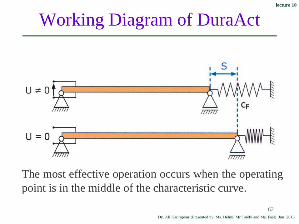
Working Diagram of DuraAct
In most cases the actuator acts against an elastic
structure, e.g. when a spring or a metal sheet is
deformed (next Fig). If the load is represented by a
spring (characteristic curve of the spring) with
stiffness of cF, the resulting operating point is the
intersection of the load line with the actuator
characteristic curve.
61
lecture 10
Dr. Ali Karimpour (Presented by: Ms. Helmi, Mr Talebi and Ms. Faal) Jun 2015
Working Diagram of DuraAct
62
The most effective operation occurs when the operating
point is in the middle of the characteristic curve.

lecture 10
Dr. Ali Karimpour (Presented by: Ms. Helmi, Mr Talebi and Ms. Faal) Jun 2015
Parameters for Bender Actuators
DuraAct actuators are usually glued to a substrate
and transfer the contraction over the whole surface.
In such a configuration, theDuraAct / substrate
combination acts as a bender actuator.
Bender actuators provide fast, high-precision and
repeatable deflection and are used in a wide range of
applications.
63

lecture 10
Dr. Ali Karimpour (Presented by: Ms. Helmi, Mr Talebi and Ms. Faal) Jun 2015
Parameters for Bender Actuators
DuraAct patch transducers are based on the
transverse piezo effect,and therefore
contract with an electric field applied.
The bender flexes and exerts a normal
force as shown below.
64

lecture 10
Dr. Ali Karimpour (Presented by: Ms. Helmi, Mr Talebi and Ms. Faal) Jun 2015
65
Parameters for Bender Actuators

lecture 10
Dr. Ali Karimpour (Presented by: Ms. Helmi, Mr Talebi and Ms. Faal) Jun 2015
Parameters for Bender Actuators
66
For the free, unblocked bender, the free deflection is
W0.
The force required to reduce the deflection to zero is
called the bender blocking force FBW. It is
significantly smaller than the actuator blocking
force. The line through these two points, gives the
characteristic curve for the bender.

lecture 10
Dr. Ali Karimpour (Presented by: Ms. Helmi, Mr Talebi and Ms. Faal) Jun 2015
Parameters for Bender Actuators
67

lecture 10
Dr. Ali Karimpour (Presented by: Ms. Helmi, Mr Talebi and Ms. Faal) Jun 2015
Parameters for Bender Actuators
68
lecture 10
Dr. Ali Karimpour (Presented by: Ms. Helmi, Mr Talebi and Ms. Faal) Jun 2015
Parameters for Bender Actuators
These figures show curves relating the maximum
deflection W0 and the maximum force FBW to the
substrate thickness and elasticity.
These diagrams show the actual deflections and
forces measured with 50 mm substrate samples
made of different materials and a P-876.A15
DuraAct patch transducer.
69

lecture 10
Dr. Ali Karimpour (Presented by: Ms. Helmi, Mr Talebi and Ms. Faal) Jun 2015
To determine the required electrical power for
successful actuator operation, the electrical
capacitance must be known.
Typical DuraAct capacitances are in the
nanofarad range and can be found in the
datasheets.
The electrical capacitance, C, depends on the
piezoceramic type, thickness and area.
70
Power Requirements of DuraAct

lecture 10
Dr. Ali Karimpour (Presented by: Ms. Helmi, Mr Talebi and Ms. Faal) Jun 2015
71
Power Requirements of DuraAct
For an estimation of the average electrical power, Pm,
knowledge of the operating voltage range and the
excitation frequency is necessary.

lecture 10
Dr. Ali Karimpour (Presented by: Ms. Helmi, Mr Talebi and Ms. Faal) Jun 2015
Power Requirements of DuraAct
72
The patch transducers ideally have a
symmetrical structure, i.e. when the transducer is
bent, the same quantity of charge with opposite
sign is generated on both electrode surfaces; it
would not be possible to measure a potential
difference. This makes it necessary to bond the
transducer onto a substrate (e.g. aluminum, CRP or
GRP material), thus producing the conventional
bender structure.

lecture 10
Dr. Ali Karimpour (Presented by: Ms. Helmi, Mr Talebi and Ms. Faal) Jun 2015
73
Power Requirements of DuraAct

lecture 10
Dr. Ali Karimpour (Presented by: Ms. Helmi, Mr Talebi and Ms. Faal) Jun 2015
74
Power Requirements of DuraAct
lecture 10
Dr. Ali Karimpour (Presented by: Ms. Helmi, Mr Talebi and Ms. Faal) Jun 2015
75
Previous picture shows the power output as a
function of the displacement.
Displacement charge and power .
It is therefore particularly important to analyze
the energy sources available and to develop a
mechanical design adapted to them which allows
optimum conversion of mechanical energy into
electrical.
Power Requirements of DuraAct

lecture 10
Dr. Ali Karimpour (Presented by: Ms. Helmi, Mr Talebi and Ms. Faal) Jun 2015
76
There is an almost linear relationship between power
output and excitation frequency. It is also possible to
see a shift of the optimum load range to smaller values
at higher excitation frequency.
Power Requirements of DuraAct

lecture 10
Dr. Ali Karimpour (Presented by: Ms. Helmi, Mr Talebi and Ms. Faal) Jun 2015
77
Why Dura Act?
Custom DuraAct Patch Transducers Flexible choice of size
Flexible choice of thickness and thus bending
ability
Flexible choice of piezoceramic material
Variable design of the electrical connections
Combined actuator/sensor applications, even
with
several piezoceramic layers
Multilayer piezo elements
Arrays

lecture 10
Dr. Ali Karimpour (Presented by: Ms. Helmi, Mr Talebi and Ms. Faal) Jun 2015
Research
Industry
Used for integration in structures For adaptive Systems
Energy harvesting
Structural health monitoring.
Printers
78
Fields of Application

lecture 10
Dr. Ali Karimpour (Presented by: Ms. Helmi, Mr Talebi and Ms. Faal) Jun 2015
Problems
بگوییدودادهیحتوضاختصاربهراپیزوالکتریکاثرعکسوپیزوالکتریکاثر-1دارد؟کاربردعملگرهادرکداموسنسوردرکدام
چهوچیستدیگرهایجنساززیرالیهیکبهtransducerچسباندندلیل-2دارد؟دنبالبهاثراتی
واستنیوتنDuraact256))عملگرپیزوالکتریک(FB)کنندهقفلنیروی-3باشدمیمیکرومتر650آناندازهتغییرمقدارحداکثر
عملگرمشخصهرسماستمطلوب(الفبیابیدراسیستممطلوبکارنقطه(بآنسختیریبضکهکنیممدلفنریباراشکلتغییربرابردرعملگرمقاومتاگر(ج
CF=360N/mmبیابیدراعملگراینکارنقطهحالتایندرباشد
79
باشدولت300ولتاژسویینگوباشد90nFقطعهاینخازناندازهحالتیکهدر(د(بگیریددرنظر2Hzرافرکانس)بیابیدراتوانمتوسطمقدار
.کنیدمحاسبهراتوانماکزیمممقدار(ه

lecture 10
Dr. Ali Karimpour (Presented by: Ms. Helmi, Mr Talebi and Ms. Faal) Jun 2015
http://piceramic.com/products/duraact-piezoelectric-transducer.html
http://www.piezo.ws/piezo_products/Piezo-Patch-
Transducer/index.php
http://www.materialstoday.com/electronic-
properties/products/duraact-power-piezo-composite-patch-transducer/
http://piceramic.com/
80
http://www.roymech.co.uk/Related/Hydrostatics/Hydraulic_moto
rs.html
http://hydraulicspneumatics.com/200/FPE/MotorsActuators/Artic
le/False/6426/FPE-
MotorsActuatorshttp://dta.eu/hydraulics/hydraulic-motors
کتاب هیدرولیک صنعتی تالیف محسن دالیلی و احمدرضا مدینه
References

lecture 10
Dr. Ali Karimpour (Presented by: Ms. Helmi, Mr Talebi and Ms. Faal) Jun 2015
http://en.wikipedia.org/wiki/Actuator
http://www.ifps.org/Education/WhitePapers/PneumaticCylinders.
htm
http://encyclopedia.che.engin.umich.edu/Pages/TransportStorage/
Actuators/Actuators.html
81
References


