��© Crown copyr�ght 2008
AAIB Bulletin: 2/2008 F-GRJO EW/C2007/01/02
INCIDENT
Aircraft Type and Registration: Bombard�er CRJ�00ER, F-GRJO
No & Type of Engines: 2 General Electr�c CF34-3A� turbofan eng�nes
Year of Manufacture: �999
Date & Time (UTC): �7 January 2007 at 2�34 hrs
Location: Runway 20, Southampton A�rport
Type of Flight: Commerc�al A�r Transport (Passenger)
Persons on Board: Crew - 3 Passengers - 33
Injuries: Crew - None Passengers - None
Nature of Damage: None, precaut�onary removal of nose land�ng gear for �nspect�on
Commander’s Licence: A�rl�ne Transport P�lot’s L�cence
Commander’s Age: 47 years
Commander’s Flying Experience: 7,500 hours (of wh�ch 5,000 were on type) Last 90 days - �50 hours Last 28 days - 40 hours
Information Source: AAIB F�eld Invest�gat�on
Synopsis
The a�rcraft suffered a fa�lure of the No 3 hydraul�c system when lower�ng the land�ng gear on approach. The commander took what he bel�eved to be the necessary act�ons pr�or to land�ng but w�thout apparent reference to the QRH. As a result the a�rcraft landed w�th one of the No 3 hydraul�c system pumps st�ll runn�ng and the nosewheel steer�ng On, contrary to �nstruct�ons �n the Qu�ck Reference Handbook (QRH). Th�s resulted �n an uncommanded steer�ng �nput to the r�ght after touchdown and the a�rcraft departed the runway.
History of the flight
The crew reported for duty at �625 hrs at Katow�ce �n Poland and had completed an uneventful flight to Paris
Charles de Gaulle A�rport. At 2039 hrs they departed
Par�s for Southampton, tak�ng off at 2049 hrs w�th the
co-p�lot act�ng as handl�ng p�lot. The takeoff and cru�se
went w�thout �nc�dent and the a�rcraft was establ�shed
on the ILS for Runway 20 at Southampton w�th the
autop�lot engaged. At a range of about 6.5 nm, w�th the
a�rcraft descend�ng through 2,000 feet QNH and w�th
20º of flap set, the co-pilot called for the landing gear to
be lowered. The commander selected the gear DOWN
and the land�ng gear lowered w�th the three green gear
�nd�cator l�ghts �llum�nat�ng.
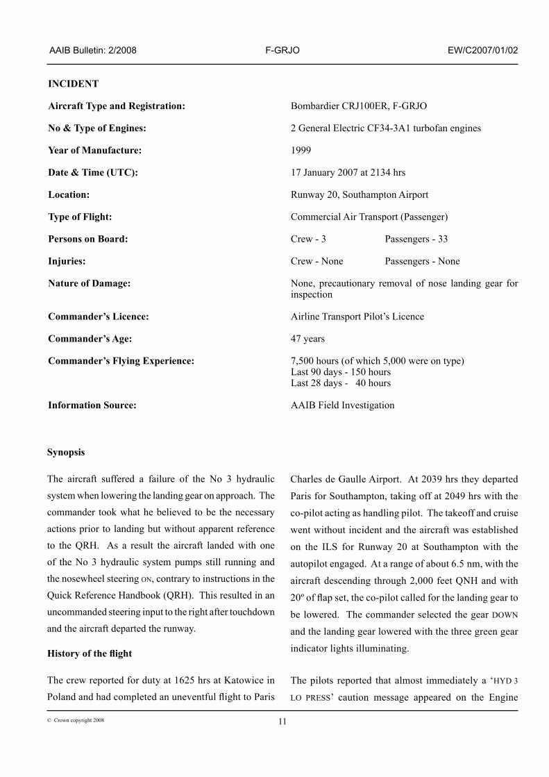
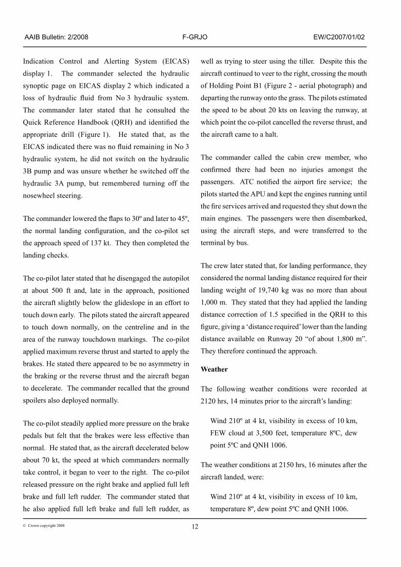
The p�lots reported that almost �mmed�ately a ‘HyD 3
LO PRESS’ caut�on message appeared on the Eng�ne
�2© Crown copyr�ght 2008
AAIB Bulletin: 2/2008 F-GRJO EW/C2007/01/02
Ind�cat�on Control and Alert�ng System (EICAS)
d�splay �. The commander selected the hydraul�c
synopt�c page on EICAS d�splay 2 wh�ch �nd�cated a
loss of hydraulic fluid from No 3 hydraulic system.
The commander later stated that he consulted the
Quick Reference Handbook (QRH) and identified the
appropr�ate dr�ll (F�gure �). He stated that, as the
EICAS indicated there was no fluid remaining in No 3
hydraul�c system, he d�d not sw�tch on the hydraul�c
3B pump and was unsure whether he sw�tched off the
hydraul�c 3A pump, but remembered turn�ng off the
nosewheel steer�ng.
The commander lowered the flaps to 30º and later to 45º,
the normal landing configuration, and the co-pilot set
the approach speed of �37 kt. They then completed the
land�ng checks.
The co-p�lot later stated that he d�sengaged the autop�lot
at about 500 ft and, late �n the approach, pos�t�oned
the a�rcraft sl�ghtly below the gl�deslope �n an effort to
touch down early. The p�lots stated the a�rcraft appeared
to touch down normally, on the centrel�ne and �n the
area of the runway touchdown mark�ngs. The co-p�lot
appl�ed max�mum reverse thrust and started to apply the
brakes. He stated there appeared to be no asymmetry �n
the brak�ng or the reverse thrust and the a�rcraft began
to decelerate. The commander recalled that the ground
spo�lers also deployed normally.
The co-p�lot stead�ly appl�ed more pressure on the brake
pedals but felt that the brakes were less effect�ve than
normal. He stated that, as the a�rcraft decelerated below
about 70 kt, the speed at wh�ch commanders normally
take control, �t began to veer to the r�ght. The co-p�lot
released pressure on the r�ght brake and appl�ed full left
brake and full left rudder. The commander stated that
he also appl�ed full left brake and full left rudder, as
well as try�ng to steer us�ng the t�ller. Desp�te th�s the
a�rcraft cont�nued to veer to the r�ght, cross�ng the mouth
of Hold�ng Po�nt B� (F�gure 2 - aer�al photograph) and
depart�ng the runway onto the grass. The p�lots est�mated
the speed to be about 20 kts on leav�ng the runway, at
wh�ch po�nt the co-p�lot cancelled the reverse thrust, and
the a�rcraft came to a halt.
The commander called the cab�n crew member, who confirmed there had been no injuries amongst the
passengers. ATC notified the airport fire service; the
p�lots started the APU and kept the eng�nes runn�ng unt�l
the fire services arrived and requested they shut down the
ma�n eng�nes. The passengers were then d�sembarked,
us�ng the a�rcraft steps, and were transferred to the
term�nal by bus.
The crew later stated that, for land�ng performance, they
cons�dered the normal land�ng d�stance requ�red for the�r
land�ng we�ght of �9,740 kg was no more than about
�,000 m. They stated that they had appl�ed the land�ng distance correction of 1.5 specified in the QRH to this
figure, giving a ‘distance required’ lower than the landing
d�stance ava�lable on Runway 20 “of about �,800 m”.
They therefore cont�nued the approach.
Weather
The follow�ng weather cond�t�ons were recorded at
2�20 hrs, �4 m�nutes pr�or to the a�rcraft’s land�ng:
W�nd 2�0º at 4 kt, v�s�b�l�ty �n excess of �0 km,
FEW cloud at 3,500 feet, temperature 8ºC, dew
po�nt 5ºC and QNH �006.
The weather cond�t�ons at 2�50 hrs, �6 m�nutes after the
a�rcraft landed, were:
W�nd 2�0º at 4 kt, v�s�b�l�ty �n excess of �0 km,
temperature 8º, dew po�nt 5ºC and QNH �006.

�3© Crown copyr�ght 2008
AAIB Bulletin: 2/2008 F-GRJO EW/C2007/01/02
HYD 3 LO PRESS Msg
Yes
TR RJ/98, Apr 05/07
ABNORM 10--5
QUICK REFERENCEHANDBOOKCSP A--022
HYDRAULIC SYSTEMMALFUNCTIONS
NOTEIf during the accomplishment of a hydraulic system lowpressure procedure, a second system also fails,disregard both single system failures and proceed directlyto the applicable double system failure procedure.
TO PREVENT FLIGHT CONTROL UNDAMPED VIBRATION:
ALTITUDE LIMITATION AIRSPEED LIMITATION
Do not exceed 31,000 feet Do not exceed 250 KIAS or 0.55 Machwhichever is lower
(1) HYDRAULIC 3B pump ON. . . . . . . . . . . . . . . . . . . . . . . . . . . . . .
(2) Hydraulic pressure and fluid quantity MONITOR. . . . . . . . . . .
System 3 quantity readout is less than 5%, or pressure is lessthan 1800 psi, or pressure is rapidly decreasing:
(3) HYDRAULIC 3A and 3B pumps OFF. . . . . . . . . . . . . . . . .
(4) HYDRAULIC page andFLIGHT CONTROLS pages REVIEW. . . . . . . . . . . . . . . . .
AFFECTED SYSTEMS
HYDRAULIC SYNOPTIC
COMPONENT SYSTEM 3
Inboard Brakes(when system 3 accumulatorpressure is depleted)
INOPERATIVE
Normal Landing Gear(extension and retraction)
INOPERATIVE
Nosewheel SteeringINOPERATIVE
(may result in nose wheelshimmy)
Parking Brake INOPERATIVE
(5) Land at the nearest suitable airport.
Prior to landing:
(6) N/W STRG OFF. . . . . . . . . . . . . . . . . . . . . . . . . . . . . . . . . . .
(7) LDG GEAR lever DN. . . . . . . . . . . . . . . . . . . . . . . . . . . . . . . .
(8) LANDING GEARMANUAL RELEASE PULL. . . . . . . . . . . . . . . . . . . . . . . . .
TO FULL EXTENSION
B
Figure 1
QRH dr�ll

�4© Crown copyr�ght 2008
AAIB Bulletin: 2/2008 F-GRJO EW/C2007/01/02
Inspection of incident site
The a�rcraft had stopped �n a grassed area �6 m to
the r�ght of Runway 20, d�splaced a d�stance of 34 m
from the runway centrel�ne. From the tyre marks �t
was determ�ned that both sets of ma�nwheels, and the
nosewheels, had left the runway at the junct�on w�th
Tax�way Bravo and then entered the grassed area, w�th
the nosewheels hav�ng travell�ng 6� m on the grass.
F�gure 2 �s an aer�al photograph of the locat�on �n wh�ch
the tyre marks are v�s�ble. In F�gure 3 �t can be seen that
the marks from the nosewheels are closer to the marks
of the r�ght ma�nwheels than to the marks of the left
ma�nwheels, �nd�cat�ng that the a�rcraft was ‘sk�dd�ng’
sl�ghtly to the left. The marks from both the �nboard
and outboard left ma�nwheels were cons�stent w�th all
four brakes funct�on�ng normally, and w�th d�fferent�al
brak�ng to the left. There were heavy scrubb�ng marks
from the two nosewheel tyres, and there was a d�st�nct
narrow l�ne outboard of the mark, left by the tread of the left nosewheel tyre, see F�gure 4. Th�s l�ne was cons�stent w�th the tyre ch�ne (a c�rcular r�dge on the outboard side of the tyre designed to deflect water on wet runways) touch�ng the runway.
The torque l�nk, wh�ch turns the steerable port�on of the nose gear and wh�ch �s rout�nely d�sconnected dur�ng tow�ng operat�ons, was found to be connected.
In summary, the ev�dence from the tyres and ground marks was cons�stent w�th the a�rcraft veer�ng to the right after landing, under the influence of ‘nose right’ steer�ng of the nose gear, w�th heavy d�fferent�al brak�ng of the left ma�nwheels caus�ng ‘scrubb�ng’ of the nosewheel tyres to the r�ght.
Runway state
The runway state at 2�20 hrs was descr�bed as dry along the full length. The runway surface
Figure 2
Hold�ng po�nt B�, Runway 20

�5© Crown copyr�ght 2008
AAIB Bulletin: 2/2008 F-GRJO EW/C2007/01/02
Figure 3Tyre marks, F-GRJO
Figure 4Tyre marks - nosewheels
fr�ct�on was assessed shortly after the �nc�dent. The measured surface fr�ct�on values were h�gher than the Ma�ntenance Plann�ng Level�, and were close to, and �n some cases exceeded, the Des�gn Object�ve Level. It was concluded that runway surface fr�ct�on was not a factor �n th�s �nc�dent.
Flight Recorders
The two solid-state flight recorders were replayed at the AAIB; both had retained a recording of the incident land�ng and the events �mmed�ately preced�ng �t. Wh�lst recorded rad�o commun�cat�ons were �n Engl�sh, all conversat�on between the crew was conducted �n French and the Bureau d’Enquetes et d’Analyses (French acc�dent �nvest�gat�on author�ty) prov�ded an Engl�sh translat�on. The co-p�lot was the handl�ng p�lot for the approach and land�ng. The commander ass�sted the co-p�lot dur�ng the rollout.
Footnote
� As defined in CAA publication CAP 683.

�6© Crown copyr�ght 2008
AAIB Bulletin: 2/2008 F-GRJO EW/C2007/01/02
The FDR recorded a number of parameters relevant
to th�s �nvest�gat�on, �nclud�ng the brake ‘pressure
ava�lable’ to the �nboard and outboard wheel brak�ng
systems, together w�th d�screte (ON or OFF) parameters
for the presence of low hydraul�c pressure on each of
the a�rcraft’s three hydraul�c systems. Ind�v�dual wheel
brake pressures and data from the nosewheel steer�ng
system were not recorded. Pert�nent parameters
recorded dur�ng the approach and land�ng are shown
�n F�gure 5.
The flight recorders showed that the initial approach
was uneventful. At 2,000 ft amsl, w�th the autop�lot
engaged and Flap 20 selected, the a�rcraft �ntercepted
the local�ser from the left. It then captured and
descended on the gl�deslope. Shortly after, at �,830 ft
amsl (�,786 ft aal), the land�ng gear was lowered and
the �nboard brake pressure ava�lable began to reduce
from 3,000 ps�. Outboard brake pressure ava�lable
rema�ned close to 3,000 ps�. Flap 30 was selected.
F�fteen seconds elapsed before the land�ng gear
�nd�cated that �t was locked down. Inboard brake
pressure ava�lable had reduced to 2,200 ps� by that t�me
before beg�nn�ng to recover slowly towards 2,300 ps�.
One second after the land�ng gear �nd�cated ‘down
and locked’ a No 3 hydraul�c system low pressure
warn�ng was recorded on the FDR, also aud�ble as a
warn�ng ch�me on the CVR. The crew selected the
hydraul�c page on the EICAS d�splay just before the
a�rcraft was cleared to land and two m�nutes before
the a�rcraft touched down. The co-p�lot commented
that they would not have the �nboard brakes and that
the runway was short. The commander responded that
the a�rcraft was not heavy and then adv�sed the cab�n
attendant that they would be land�ng �n one m�nute.
The co-p�lot further commented that they ought to
analyse the s�tuat�on and asked the commander �f he
wanted to cont�nue the approach. The commander stated that they would cont�nue.
Flap 45 was selected at 900 ft aal and the crew carr�ed out the ‘before land�ng’ checkl�st. The co-p�lot adv�sed the commander that they would have reduced brak�ng and no steer�ng, and asked h�m �f �t was not better to d�vert to London. The commander restated to the co-p�lot that they would cont�nue w�th the land�ng and request a tow �f �t became necessary. The autop�lot was d�sconnected at 325 ft aal. The a�rcraft touched down at �32 kt just to the left of the runway centrel�ne2 and the ground spo�lers deployed symmetr�cally. The a�rcraft yawed �.5° to the left and began to slow; the inner brake pressure available aga�n began to reduce. As the a�rcraft was derotated and the ‘we�ght-on-wheels’ sw�tch for the nose gear was made, the a�rcraft yawed to the r�ght by 3°. Progress�vely �ncreas�ng left rudder was appl�ed wh�ch arrested the yaw for a per�od of about four seconds and reverse thrust was selected. Eng�ne N� and reverser deployment parameters showed that max�mum symmetr�cal reverse thrust was used. S�x seconds after ma�nwheel touchdown the co-p�lot stated that he had a problem and the commander offered h�s ass�stance. Recorded local�ser values �nd�cated that the a�rcraft was head�ng and track�ng to the r�ght of the runway centrel�ne and towards the r�ght s�de of the runway at that stage. Seven seconds after touchdown, w�th a�rspeed and �nner brake pressure ava�lable hav�ng reduced to 97 kt and 2,000 ps� respect�vely, the a�rcraft briefly yawed 2° to the left before, w�th full left rudder now be�ng appl�ed, yaw�ng progress�vely to the r�ght at a rate of 2.7º per second.
From the changes �n recorded values of p�tch att�tude and normal accelerat�on, �t �s l�kely that the nose gear left the paved surface at an a�rspeed of about 50 kt wh�lst
Footnote
2 Der�ved from the record�ng of local�ser dev�at�on.

�7© Crown copyr�ght 2008
AAIB Bulletin: 2/2008 F-GRJO EW/C2007/01/02
Figure 5
FDR plot, F-GRJO

�8© Crown copyr�ght 2008
AAIB Bulletin: 2/2008 F-GRJO EW/C2007/01/02
the ma�n gear followed one second later. The a�rcraft came to a halt on a head�ng of 2�5°M, �9 seconds after ma�n gear touchdown. The crew adv�sed ATC that they had had a hydraul�c problem and had been unable to maintain good braking action, but that there was no fire.
The CVR showed that, dur�ng the d�scuss�ons �mmed�ately after the a�rcraft had come to a halt, the crew debated whether they should have aborted the land�ng. They also referenced the checkl�st appropr�ate to a No 3 hydraul�c system low pressure warn�ng. W�th regard to the status of the No 3 hydraul�c system, the commander commented that “OFF OR NOT, IT DIDN’T CHANGE ANyTHING”.3 The co-p�lot then requested “STEERING OFF, yOU CAN PUT IT
OFF”. The sound of a sw�tch select�on was then recorded before the commander repl�ed “OFF, SO I DID NOT PUT IT...” Further checkl�st d�scuss�on centred around the factor�ng of an �ncrease �n land�ng d�stance by 50% and adv�ce to brake carefully and use max�mum reverse thrust.
Throughout the land�ng roll the recorded values of long�tud�nal accelerat�on showed that the a�rcraft was be�ng slowed effect�vely. However, �n the absence of actual recorded brake pressures, �t was not poss�ble to determ�ne whether any degradat�on �n the �nner brak�ng system had occurred as a result of the reduced �nner brake pressure ava�lable.
Aircraft information
The Bombard�er CRJ �s a tw�n-eng�ned, 50-seat reg�onal a�rl�ner, and over �,000 have been bu�lt (all var�ants).
The ma�n forces that decelerate the a�rcraft after land�ng are spo�lers wh�ch dump l�ft and act as a�rbrakes, thrust reversers and four ant�-sk�d brakes, one mounted on each of the four ma�nwheels.
Footnote
3 Engl�sh translat�on prov�ded by the BEA.
There are 3 hydraul�c systems on th�s a�rcraft type. The No 3 hydraul�c system has two electr�cally-operated pumps to prov�de power, pump 3A and pump 3B, and these are �nstalled �n the left and r�ght w�ng-to-fuselage fa�r�ngs respect�vely. A schemat�c of the hydraul�c system �s shown �n F�gure 6. From th�s �t can be seen that the only hydraul�c power supply for the nose gear door, the nose gear steer�ng, and the land�ng gear retract�on �s from No 3 hydraul�c system. The �nboard brakes (both left and r�ght) are also suppl�ed from No 3 system. F�gure 6 shows that the outboard brakes are powered by No 2 hydraul�c system, and the �nboard brakes by No 3 hydraul�c system.
Both the outboard and �nboard brakes have a hydraul�c accumulator. If e�ther No 2 or No 3 hydraul�c system fa�ls, then the brakes on the fa�led system can be appl�ed four or five times before the accumulator is depleted. Therefore, �n the case of a fa�lure to No 2 or No 3 hydraul�c system, one set of brakes w�ll operate normally, the other (on the fa�led system) w�ll operate sat�sfactor�ly but only for four or five applications on the brake pedals, and thereafter th�s set of brakes w�ll be �neffect�ve.
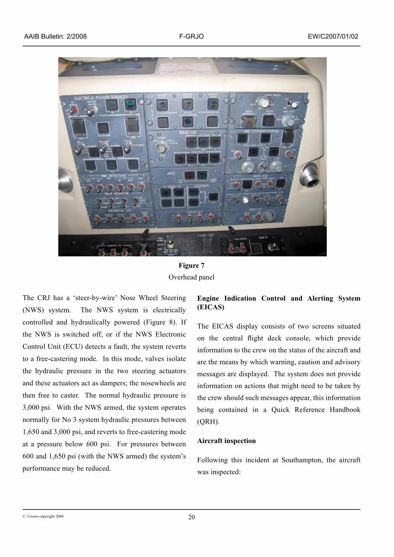
There are selector sw�tches for the hydraul�c pumps on the overhead panel �n the cockp�t, as �n F�gure 7. The normal operat�ng pos�t�on for all four sw�tches �s down: Pump � AUTO, Pump 3A ON, Pump 3B AUTO, and Pump 2 AUTO. D�rect�onal control on the land�ng roll �s ma�nta�ned by a comb�nat�on of rudder, asymmetr�c brakes and nosewheel steer�ng. The nosewheels can be turned to 70° to the left or r�ght by us�ng the handwheel control un�t s�tuated to the left of the left p�lot’s seat, or to approx�mately 8° to the left or r�ght by appl�cat�on of the rudder pedals. It �s normal operat�ng pract�ce for the handwheel to be used at speeds of less than 70 kt .

�9© Crown copyr�ght 2008
AAIB Bulletin: 2/2008 F-GRJO EW/C2007/01/02
Figure 6
Hydraul�c system schemat�c
20© Crown copyr�ght 2008
AAIB Bulletin: 2/2008 F-GRJO EW/C2007/01/02
The CRJ has a ‘steer-by-w�re’ Nose Wheel Steer�ng
(NWS) system. The NWS system �s electr�cally
controlled and hydraul�cally powered (F�gure 8). If
the NWS �s sw�tched off, or �f the NWS Electron�c
Control Un�t (ECU) detects a fault, the system reverts
to a free-caster�ng mode. In th�s mode, valves �solate
the hydraul�c pressure �n the two steer�ng actuators
and these actuators act as dampers; the nosewheels are
then free to caster. The normal hydraul�c pressure �s
3,000 ps�. W�th the NWS armed, the system operates
normally for No 3 system hydraul�c pressures between
�,650 and 3,000 ps�, and reverts to free-caster�ng mode
at a pressure below 600 ps�. For pressures between
600 and �,650 ps� (w�th the NWS armed) the system’s
performance may be reduced.
Engine Indication Control and Alerting System (EICAS)
The EICAS d�splay cons�sts of two screens s�tuated on the central flight deck console, which provide �nformat�on to the crew on the status of the a�rcraft and are the means by wh�ch warn�ng, caut�on and adv�sory messages are d�splayed. The system does not prov�de �nformat�on on act�ons that m�ght need to be taken by the crew should such messages appear, th�s �nformat�on be�ng conta�ned �n a Qu�ck Reference Handbook (QRH). Aircraft inspection
Follow�ng th�s �nc�dent at Southampton, the a�rcraft was �nspected:
Figure 7 Overhead panel

2�© Crown copyr�ght 2008
AAIB Bulletin: 2/2008 F-GRJO EW/C2007/01/02
Figure 8NWS schemat�c

22© Crown copyr�ght 2008
AAIB Bulletin: 2/2008 F-GRJO EW/C2007/01/02
a. The left nosewheel tyre was found to have
regular transverse marks at approx�mately
�2° to the wheel ax�s, and the tyre ch�ne,
wh�ch usually shows no s�gns of wear, had
s�gns of heavy load�ng, see F�gures 9 and �0.
The or�entat�on of the marks �s cons�stent w�th
both nosewheel tyres be�ng h�ghly loaded and
‘scrubbed’ to the r�ght, oppos�ng the a�rcraft’s
motion. There were no significant marks on the ch�ne on the r�ght nose tyre.
b. The nose gear leg and assoc�ated structure was �nspected and no damage was seen.
c. W�th the a�rcraft on jacks the nose gear steer�ng system was funct�oned and the r�gg�ng values were checked, w�th noth�ng abnormal be�ng
Figure 9 (left)Tyre ch�ne, left nosewheel
Figure 10 (right)Tyre tread, left nosewheel

23© Crown copyr�ght 2008
AAIB Bulletin: 2/2008 F-GRJO EW/C2007/01/02
found. The free-caster�ng mode was checked,
firstly with the hydraulics ON (at the normal
3,000 ps�) and the steer�ng OFF, and secondly
w�th the steer�ng ON and the hydraul�cs
OFF. In both cases the upper l�nk could be
rotated by hand, �nd�cat�ng that the nose gear
system has reverted to free-caster�ng mode as
expected.
d. There was a leak at the outlet of hydraul�c
pump 3A at the elbow jo�nt. An ‘O’ r�ng had
ruptured and the fa�lure appeared cons�stent
with a rapid loss of fluid. A locking wire was
missing between the pump and the elbow fitting
and e�ther th�s, or the �ncorrect �nstallat�on of
the ‘O’ r�ng, appeared to be the cause of the
fa�lure.
e. There was a leak at the flexible outlet hose
on pump 3B. This leak was confirmed by
ra�s�ng the system pressure unt�l a leak was
detected, w�th a slow and constant loss of
fluid. No loose fittings or damage could be
found, although the lock�ng w�re between the
pump and elbow fitting was missing (as on
pump 3A). The short length of outlet hose
was al�gned �n a gentle ‘S’ shape, and th�s
may have �nduced extra, and unnecessary,
tens�on �n the �nstallat�on.
f. Apart from heavy contam�nat�on of mud and
grass, noth�ng abnormal was found w�th the
tyres and brakes on both ma�n gears.
g. The fans and �ntakes of both eng�nes were
found contam�nated by mud. More deta�led
�nspect�on revealed no damage to e�ther
compressor, and subsequent eng�ne runs
confirmed that the performance of the engines
was not significantly degraded.
Further engineering investigation - nosewheel steering
Most of the components of the nose gear steer�ng
system, �nclud�ng the nose leg and the steer�ng
Electron�c Control Un�t, were removed from the
a�rcraft for further exam�nat�on. The components were
�nspected �nd�v�dually and used to recreate on a r�g, as
far as pract�cable, the nose gear steer�ng system that
was on F-GRJO.
The �nd�v�dual �nspect�ons of the components revealed
nothing significant. However, the rig test revealed that,
�f the pressure was between 650 and �,650 ps� when
the ‘we�ght-on-wheels’ sw�tch was act�vated, then the
nosewheel steered slowly to the r�ght at a rate of about
�º per second. The torque was typ�cally 3,000 lbf-�n,
wh�ch �s almost an order of magn�tude less that that
for normal operat�on. Above �,650 ps� the steer�ng
system would steer normally; below 650 psi the system
went �nto free-caster�ng mode. The dr�ft requ�red that
the steer�ng system be sw�tched ON, and for hydraul�c
power to be prov�ded, effect�vely requ�r�ng e�ther pump
3A or 3B (or both) to be ON. Such a dr�ft would occur
for all a�rcraft w�th th�s NWS system, the d�rect�on of
the dr�ft depend�ng on the part�cular a�rcraft.
The 3A and 3B hydraul�c pumps were sent for �nspect�on.
There were no significant defects and no signs of
overheat�ng.
Var�ous des�gn cases for the nosewheel steer�ng were
d�scussed w�th the nose gear manufacturer. Th�s
�ncluded an assessment of how much steer�ng torque
was ava�lable for a g�ven hydraul�c system pressure, as
well as how much torque would be requ�red for a g�ven

24© Crown copyr�ght 2008
AAIB Bulletin: 2/2008 F-GRJO EW/C2007/01/02
nosewheel angle. The d�scuss�on concluded that, w�th hydraul�c pressures �n the range of 650 to �,650 ps�, there was sufficient torque to steer the nosewheel to at least 4°. Further engineering investigation - hydraulic leaks
The Ma�ntenance Manual was rev�ewed w�th the manufacturer and the operator. The rev�ew concluded that the word�ng �n the procedures for �nstallat�on and removal of the hydraul�c pump could be �mproved to ensure that pumps are correctly installed and fittings correctly w�relocked. The operator noted that, as a result of the�r �nternal �nvest�gat�on, they �ssued an �nternal techn�cal bullet�n to cover ‘O’ r�ng �nstallat�on, hydraul�c pump w�relock�ng and �nstallat�on of hydraul�c hoses. For the�r part, the manufacturer made m�nor changes �n the ma�ntenance manual.
Further engineering investigation - possibility of adverse rudder effectiveness
The a�rcraft manufacturer cons�dered the poss�b�l�ty that the jet efflux from the thrust reversers, passing over a rudder surface fully deflected to the left, had an effect on a�rcraft d�rect�onal control. They concluded that there was a poss�b�l�ty of some reduct�on �n rudder effect�veness at lower a�rspeeds but not of a reversal of the rudder’s control effect. To support th�s, the manufacturer referred to w�nd tunnel and ‘on-a�rcraft’ tests conducted �n �994 and �995.
Analysis
Dur�ng th�s �nvest�gat�on, r�g test�ng clearly demonstrated a scenar�o �n wh�ch the nosewheels would slowly steer �n one d�rect�on w�thout any command �nput. For th�s to occur, the pressure �n the No 3 hydraul�c system needed to be �n the range of 650 to �,650 ps�, and the Nose Wheel Steer�ng to be ON, w�th the ‘we�ght-on-wheels’ sw�tch act�vated after
the nosewheel touchdown. The pressure could be �n
th�s range after a hydraul�c leak and w�th one, or both,
of the No 3 system pumps be�ng ON. Importantly, th�s
part�cular nose gear steered to the r�ght, wh�ch agreed
w�th the d�rect�on the a�rcraft veered, the tyre marks
on the runway, and damage to the left nose gear tyre
ch�ne.
The commander recalled referr�ng to the QRH. He
bel�eved he had not sw�tched on the hydraul�c 3B pump
and was unsure �f he had sw�tched off the hydraul�c
3A pump. He also bel�eved he had turned OFF the
nosewheel steer�ng.
Ev�dence from the CVR �nd�cated that no reference
was made by the crew to the QRH wh�lst a�rborne.
It prov�ded ev�dence that the Nose Wheel Steer�ng
was �n the ON pos�t�on for the approach, that �t was
not sw�tched OFF wh�lst a�rborne, �n response to the
hydraul�c fa�lure, and that �t rema�ned On for the ground
roll. In add�t�on, the CVR prov�ded ev�dence that the
sw�tches for the hydraul�c pumps 3A and 3B rema�ned
�n the On and AUTO pos�t�ons respect�vely throughout
the approach and ground roll.
The QRH dr�ll (F�gure �) would, �n th�s case, have
requ�red that the hydraul�c 3A pump, the hydraul�c 3B
pump and the nosewheel steer�ng all be sw�tched OFF.
In add�t�on �t requ�red the re-calculat�on of the land�ng
d�stance requ�red. Comments by the co-p�lot that they
should d�vert to London suggest he was concerned
about the land�ng d�stance ava�lable. Wh�lst there was,
in fact, sufficient landing distance available, the CVR
gave no �nd�cat�on that such a calculat�on was carr�ed
out by the crew pr�or to land�ng.
The crew became alerted to the hydraul�c fa�lure at a
late stage �n the approach, a l�ttle over two m�nutes pr�or

25© Crown copyr�ght 2008
AAIB Bulletin: 2/2008 F-GRJO EW/C2007/01/02
to touchdown. It �s l�kely that the commander bel�eved he had sufficient knowledge of the system, reinforced by the �nformat�on prov�ded to h�m by the EICAS, to be able to cont�nue the land�ng safely w�thout hav�ng to act�on the �tems �n the QRH.
Wh�lst th�s �nc�dent would not have occurred had the QRH been followed (�e the NWS and hydraul�c pumps 3A and 3B had been sw�tched off) there rema�ns the poss�b�l�ty that, �n another case, a hydraul�c fa�lure could occur just before touchdown. In such a case �t
would be unreasonable to expect a crew to take the appropr�ate act�ons qu�ckly enough to prevent a s�m�lar lack of controllab�l�ty on the ground. The follow�ng Safety Recommendat�on �s therefore made:
Safety Recommendation 2007-101
It �s recommended that Bombard�er Aerospace rev�ew th�s des�gn of nose gear steer�ng system, �n the CRJ�00 and other company products, to prevent uncommanded nose gear steer�ng follow�ng a hydraul�c fa�lure.


