
West Virginia Turnpike
Incident Management
EMERGENCY TRAFFIC CONTROL PLAN
Submitted To:
West Virginia Department of Transportation Division of Highways
Submitted By:
HNTB Corporation
December 21, 2011

Incident Management: Emergency Traffic Control Plan December 21, 2011
Page | i
Contents
List of Abbreviations .................................................................................................................................... iv
FIGURE 1 ‐ Overall Turnpike Map ................................................................................................................. v
Overview ....................................................................................................................................................... 1
Introduction .......................................................................................................................................... 1
FIGURE 2 – WV Turnpike Traffic Volumes............................................................................................. 1
Purpose ................................................................................................................................................. 1
Exclusions .............................................................................................................................................. 2
Evaluation ..................................................................................................................................................... 2
Incident Related Event .......................................................................................................................... 2
Weather Related Event ......................................................................................................................... 3
Procedure ...................................................................................................................................................... 4
Traffic Abatement ................................................................................................................................. 4
Speed Reduction ................................................................................................................................... 4
FIGURE 3 – Advisory Speed Limits ........................................................................................................ 6
FIGURE 4 – TRAFFIC INCIDENT FLOW CHART ............................................................................................... 7
Traffic Abatement Facilities .................................................................................................................. 8
FIGURE 5 SECTION 1 TRAFFIC ABATEMENT FACILITIES FLOW CHART ........................................................ 11
FIGURE 6 ‐ SECTION 1 ABATEMENT FACILITY MAP ..................................................................................... 12
FIGURE 7 SECTION 2 TRAFFIC ABATEMENT FACILITIES FLOW CHART ........................................................ 13
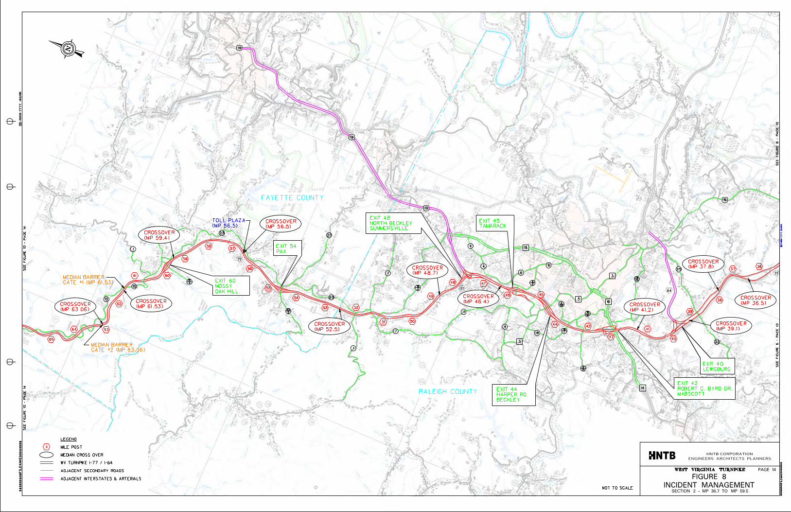
FIGURE 8 ‐ SECTION 2 ABATEMENT FACILITY MAP ..................................................................................... 14
FIGURE 9 SECTION 3 TRAFFIC ABATEMENT FACILITIES FLOW CHART ........................................................ 15
FIGURE 10 ‐ SECTION 3 ABATEMENT FACILITY MAP ................................................................................... 16

Incident Management: Emergency Traffic Control Plan December 21, 2011
Page | ii
Detour Routes ............................................................................................................................................. 17
Requirements of Detour Routes ......................................................................................................... 17
Approved Detour Routes .................................................................................................................... 17
DETOUR –A MAP ................................................................................................................................. 20
DETOUR –B MAP ................................................................................................................................. 21
DETOUR –C MAP ................................................................................................................................. 22
DETOUR –D MAP ................................................................................................................................. 23
DETOUR –E MAP ................................................................................................................................. 24
Recommended Detour Facility Additions and Upgrades ............................................................................ 25
Operational Aspects ............................................................................................................................ 25
FIGURE‐11 Existing Intersection Traffic Signal Disposition ................................................................. 28
Physical Aspects .................................................................................................................................. 29
Recommended Revisions to the Turnpike Detour Manual ................................................................. 30
Detour Signage ............................................................................................................................................ 31
Permanent Detour Signs ..................................................................................................................... 31
Dynamic Message Signs ...................................................................................................................... 33
Operation .................................................................................................................................................... 33
Resources ............................................................................................................................................ 33
Training ............................................................................................................................................... 34
Roles of Parkways Personnel ...................................................................................................................... 34
Section Foreman ................................................................................................................................. 34
State Trooper Supervisor .................................................................................................................... 35
Maintenance Crew .............................................................................................................................. 35
Turnpike Control Center (TCC) ............................................................................................................ 35
Legislation ................................................................................................................................................... 35

Incident Management: Emergency Traffic Control Plan December 21, 2011
Page | iii
Example Legislation............................................................................................................................. 36
Contacts ...................................................................................................................................................... 36

Incident Management: Emergency Traffic Control Plan December 21, 2011
Page | iv
ListofAbbreviations
MP Mile Post
PCMS Portable Changeable Message Sign
SOP Standard Operating Procedure
DMS Dynamic Message Signs
TAZ Traffic Abatement Zone
TCC Turnpike Control Center
TMC DOH Transportation Management Center
TPK WV Turnpike
WV West Virginia
WVDOH West Virginia Division of Highways
AUTHORITY West Virginia Parkways Authority

Incident Management: Emergency Traffic Control Plan December 21, 2011
Page | v
FIGURE1‐OverallTurnpikeMap

Incident Management: Emergency Traffic Control Plan December 21, 2011
Page | 1
Overview
Introduction
The West Virginia Turnpike is an 88‐mile section of controlled access interstate highway that serves as
the main route between Charleston and Princeton. The Turnpike is a high traffic volume route (See
Figure 2) which traverses mountainous terrain that is often rural and inaccessible by alternate routes.
These conditions present unique challenges regarding the need for temporary detours both in the event
of an accident or when inclement weather renders the road impassible.
AVERAGEDAILYTRAFFIC(ADT)STATSLISTEDSOUTHTONORTH
MILELOCATION ADTMARKER
9-28 Princeton to Ghent 32,000 28-40 Ghent to I-64 31,000 40-42 I-64 to Mabscott 45,000 42-44 Mabscott to Harper Rd 44,500 44-48 Harper Rd to N. Beckley 44,000 48-60 N. Beckley to Mossy 30,000 60-74 Mossy to Standard 33,000 74-78 Standard to Sharon 32,000 78-85 Sharon to Chelyan 35,300 85-90 Chelyan to Marmet 41,000 90-95 Marmet to Kanawha City 49,400 95-96 Kanawha City to Belle 56,800
FIGURE2–WVTurnpikeTrafficVolumes
Purpose
The purpose of this report is to establish a protocol and procedure to maintain traffic movements in the
event of an incident or severe weather, as well as to identify acceptable detour routes and traffic control
measures. This report also outlines duties of individuals and agencies during an event and examines
Chapter 17 of the current WV code titled Traffic Regulations and Laws of the Road, for the purpose of
identifying recommended topics of future legislation.
Incident Management: Emergency Traffic Control Plan December 21, 2011
Page | 2
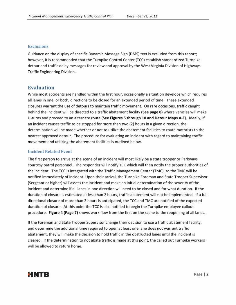
Exclusions
Guidance on the display of specific Dynamic Message Sign (DMS) text is excluded from this report;
however, it is recommended that the Turnpike Control Center (TCC) establish standardized Turnpike
detour and traffic delay messages for review and approval by the West Virginia Division of Highways
Traffic Engineering Division.
EvaluationWhile most accidents are handled within the first hour, occasionally a situation develops which requires
all lanes in one, or both, directions to be closed for an extended period of time. These extended
closures warrant the use of detours to maintain traffic movement. On rare occasions, traffic caught
behind the incident will be directed to a traffic abatement facility (See page 8) where vehicles will make
U‐turns and proceed to an alternate route (See Figures 5 through 10 and Detour Maps A‐E). Ideally, if
an incident causes traffic to be stopped for more than two (2) hours in a given direction, the
determination will be made whether or not to utilize the abatement facilities to route motorists to the
nearest approved detour. The procedure for evaluating an incident with regard to maintaining traffic
movement and utilizing the abatement facilities is outlined below.
IncidentRelatedEvent
The first person to arrive at the scene of an incident will most likely be a state trooper or Parkways
courtesy patrol personnel. The responder will notify TCC which will then notify the proper authorities of
the incident. The TCC is integrated with the Traffic Management Center (TMC), so the TMC will be
notified immediately of incident. Upon their arrival, the Turnpike Foreman and State Trooper Supervisor
(Sergeant or higher) will assess the incident and make an initial determination of the severity of the
incident and determine if all lanes in one direction will need to be closed and for what duration. If the
duration of closure is estimated at less than 2 hours, traffic abatement will not be implemented. If a full
directional closure of more than 2 hours is anticipated, the TCC and TMC are notified of the expected
duration of closure. At this point the TCC is also notified to begin the Turnpike employee callout
procedure. Figure 4 (Page 7) shows work flow from the first on the scene to the reopening of all lanes.
If the Foreman and State Trooper Supervisor change their decision to use a traffic abatement facility,
and determine the additional time required to open at least one lane does not warrant traffic
abatement, they will make the decision to hold traffic in the obstructed lanes until the incident is
cleared. If the determination to not abate traffic is made at this point, the called out Turnpike workers
will be allowed to return home.

Incident Management: Emergency Traffic Control Plan December 21, 2011
Page | 3
WeatherRelatedEvent
Snow and ice storms that occur during winter months require a formal evaluation process in order for
proper precautionary measures to take place. During such winter months, the Authority’s Director of
Operations, the Director of Maintenance and Staff, and the TMC participate in a weekly conference call
with National Weather Service and Department of Homeland Security. In addition to the weekly phone
discussions, calls are initiated on an as‐needed basis prior to anticipated major storms.
The information gleaned from these regular conversations is used to provide proper direction to
Authority maintenance personnel. During a routine expected snow event, the maintenance employees
are split into both day and night crews so that staff is available around the clock to maintain the
roadways and provide assistance with clearing of accidents. The split‐shift schedule is maintained as
needed to mitigate refreezing of ice and/or snow on the roadways.
In the event that six inches or more of snow are predicted for a 12 hour period, the Authority enacts an
“enhanced” maintenance team. In addition to the usual team, management level personnel will staff a
command post in Beckley, WV to assist in directing maintenance crews to those areas experiencing the
greatest need. Another element of the “enhanced” approach is the staging of wrecker service vehicles
at strategic placements along the Turnpike in an attempt to reduce response time and associated
motorist delay. There is a written agreement in place between the Authority and the primary and
secondary wrecker services as outlined in the “West Virginia Parkways Authority Wrecker and Towing
Services Standard Operating Procedure”. The final element of the “enhanced” maintenance team is the
deployment of Turnpike maintenance personnel in pick‐up trucks during the actual weather event to
provide accident reconnaissance and to assist in retrieval of vehicles that have left the roadway due to
adverse conditions.
With time being of the essence in reducing motorists’ delay during a weather event, the use of
technology is crucial to efficient operation of the planning and response teams. As such, the Authority
actively uses Twitter to disseminate up‐to‐date road condition and accident information to patrons.
Another use of technology to manage activities in response to an unanticipated weather event is the use
of the “One Call” programmable system that provides an automated contact and solicits a response
from Authority maintenance team members. Similarly, the Authority has adopted an interoperable
radio communication system that possesses statewide coverage and is capable of inter‐agency
communication. This system is vital to the efficient sharing of accident response requests and to the
timely notification of local authorities of weather related trouble spots or road closures and delays.
The Authority incorporates several items of its Intelligent Transportation System (ITS) to aid in managing
weather related events as well. Closed‐circuit cameras mounted in proximity to the toll barriers are
used to monitor traffic and roadway conditions. In the event that a slowdown or inclement conditions
are observed, information, such as recommended speed reduction, is disseminated to motorists through
the Dynamic Message Signs (DMS) which are controlled via the Turnpike Control Center at the Turnpike
headquarters. This system allows for real‐time observation, dissemination of current direction and
guidance, and is confirmable via a CAD system. The CAD system allows any involved agency, such as the

Incident Management: Emergency Traffic Control Plan December 21, 2011
Page | 4
WV State Office of Emergency Services, or county or metro 911 centers, to view what is being displayed
on a given DMS at any time. The systematic use of these ITS components allow the Authority to move
patrons through the Turnpike corridor during periods of inclement weather as safely and efficiently as
possible.
Procedure
TrafficAbatement
If the Foreman and State Police Supervisor determine that traffic abatement is required, the Foreman
will contact the TCC to provide an update and inform the center of the decision to use the traffic
abatement facilities. The TCC will then relay the information to the designated parties (See Figure 4,
Page 7) and post a message to the DMS indicating a road closure. The TCC will also relay the
information to the TMC which will post information to DMS signs prior to the Turnpike with estimated
closure durations.
The Foreman will then instruct the maintenance employees to begin setting traffic control at exit
interchanges and at cross‐over and/or the removable concrete median barrier gate nearest the incident
if required. Once traffic control devices are in place and traffic is turning at the exit interchanges prior to
the incident, the facilities (i.e. barrier gates or median cross‐overs) may be utilized (See pages 8 and 9
for explanation of traffic abatement facilities). Maintenance employees will intermittently stop traffic
in the opposing direction to allow vehicles that have been waiting behind the incident to make U‐turns
through the facilities and proceed in the opposite direction. To prevent excessive back‐up in the
opposing direction, traffic shall be stopped for no more than 30 minutes at a time. Traffic in the
opposing direction shall be allowed to proceed long enough to return to free‐flow between stoppages.
The TCC is to be periodically updated on the situation until it has been fully resolved.
Once the stopped traffic has been cleared, the emergency agencies and maintenance crews will
continue to work to resolve the incident while detour routing is still in place. After all obstructions have
been removed and traffic can proceed safely through the incident site, traffic control will be removed
from the abatement facilities, and the lanes will be re‐opened to traffic. The Foreman will then notify
TCC that the incident has been cleared and the TCC will relay the information to the designated parties,
including the TMC, and the detour messages will be removed from the DMS.
SpeedReduction
In order to reduce the secondary effects of traffic incidents and emergencies, such as additional
accidents, and to protect emergency responders, proper control of traffic through the incident
management area must be established. An essential part of effective incident response and traffic
management is the establishment of reduced speeds of motorists within the incident area. Initiation of
a speed reduction advisory on any portion of the Turnpike will be directed by the Section Foreman,
State Trooper Supervisor, and the TCC. Speed reductions may become feasible due to several conditions
including the following:

Incident Management: Emergency Traffic Control Plan December 21, 2011
Page | 5
Traffic Incident Not Requiring Traffic Abatement – For minor or intermediate incidents or
emergencies not requiring traffic abatement, recommended speed reductions may be
implemented through use of the existing DMSs and by displaying reduced speed
requirements on Portable Changeable Message Signs (PCMS) as needed.
Traffic Incident Requiring Traffic Abatement – For major incidents or emergencies requiring
traffic abatement efforts, speed reduction guidance should be limited to PCMS displays.
The DMS displays should be reserved for abatement messages such as detour route or
travel delay information.
Reduced visibility – During periods of fog and heavy precipitation, overhead DMS can be
utilized to alert drivers of upcoming conditions as well as advise a speed that is 10 mph
lower than the posted speed limit. In the event of fog or heavy precipitation at night, the
advisory speed should be 15 mph below the posted speed limit.
Hazardous Road Conditions – When inclement weather results in adverse road conditions,
such as snow or ice covering, speed reduction advisories may be implemented. Appropriate
speed messages may be displayed on DMS, but only when coordinated with the weather
advisory information. If travel conditions on isolated sections of the roadway warrant speed
reductions, then PCMS may be installed to relay the relevant speed message. Care must be
taken to locate PCMS installations such that they do not interfere with plowing or surface
treatment operations. PCMS may be placed prior to any weather event expected to result
in hazardous road conditions and at locations that are historically most effected by weather
systems.
Speed reduction advisories should only be implemented prior to areas of adverse conditions or when
restrictive features are present. However, frequent changes in speed limit should be avoided. The
Section Foreman and State Police Supervisor should coordinate with adjacent sections to ensure that
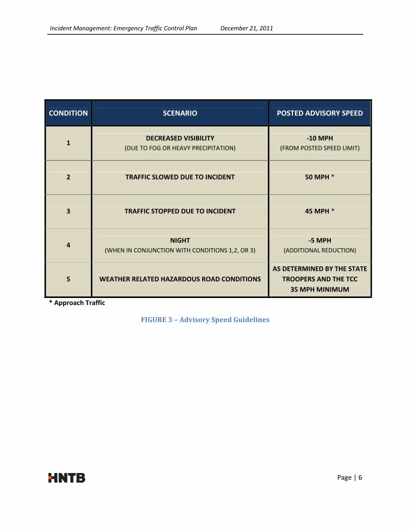
consistent speed reduction implementations are made throughout the corridor. See Figure 3 on Page 6
for advisory speed limit guidelines.
Incident Management: Emergency Traffic Control Plan December 21, 2011
Page | 6
CONDITION SCENARIO POSTED ADVISORY SPEED
1 DECREASED VISIBILITY
(DUE TO FOG OR HEAVY PRECIPITATION)
‐10 MPH
(FROM POSTED SPEED LIMIT)
2 TRAFFIC SLOWED DUE TO INCIDENT 50 MPH *
3 TRAFFIC STOPPED DUE TO INCIDENT 45 MPH *
4 NIGHT
(WHEN IN CONJUNCTION WITH CONDITIONS 1,2, OR 3)
‐5 MPH
(ADDITIONAL REDUCTION)
5 WEATHER RELATED HAZARDOUS ROAD CONDITIONS
AS DETERMINED BY THE STATE
TROOPERS AND THE TCC
35 MPH MINIMUM
* Approach Traffic
FIGURE3–AdvisorySpeedGuidelines

Page | 7
PROCEED WITH NORMAL
OPERATIONS, TRAFFIC CONTROL,
AND INCIDENT MANAGEMENT
TRAFFICINCIDENTFLOWCHART
FIGURE 4
TRAFFIC ACCIDENT
FIRST ON SCENE (STATE
TROOPER OR PARKWAYS
EMPLOYEE) NOTIFIES
TURNPIKE CONTROL CENTER
& ASSESSES POTENTIAL
TRAFFIC DELAY
SECTION FOREMAN CONTACTS THE TURNPIKE
CONTROL CENTER WITH NOTICE OF INTENT TO BEGIN
TRAFFIC ABATEMENT
MAINTENANCE CREWS SET UP TRAFFIC CONTROL FOR TEMPORARY DETOURS AND
UTILIZE ABATEMENT FACILITIES
MAINTENANCE CREWS MAINTAIN COMMUNICATION WITH THE SECTION
FOREMAN TO RE‐OPEN CLOSED LANES AND RAMPS AS OBSTRUCTIONS ARE CLEARED
THRU TRAFFIC IS RESTORED AS DIRECTED BY THE SECTION FOREMAN & STATE TROOPER
SUPERVISOR
SECTION FOREMAN NOTIFIES TURNPIKE CONTROL CENTER THAT ALL LANES ARE RE‐
OPENED
> 2 HOUR DELAY
NOTIFY TPK SECTION FOREMAN & STATE TROOPER
SUPERVISOR TO REPORT TO SCENE OF INCIDENT
AND NOTIFY TURNPIKE CONTROL CENTER TO BEGIN
THE CALLOUT PROCEDURE FOR
MAINTENANCE CREWS
< 2 HOUR DELAY
SECTION FOREMAN & STATE TROOPER
SUPERVISOR MONITOR THE INCIDENT
SITE AND NOTIFY TURNPIKE CONTROL
CENTER WHEN ALL LANES ARE CLEAR
SECTION FOREMAN & STATE
TROOPER SUPERVISOR DETERMINE
TRAFFIC WAIT TIMES WILL NOT
EXCEED AN ADDITIONAL 2 HOURS
SECTION FOREMAN & STATE TROOPER
SUPERVISOR DETERMINE TRAFFIC
WAIT TIMES WILL EXCEED AN
ADDITIONAL 2 HOURS. TRAFFIC
ABATEMENT IS INITALIZED
SECTION FOREMAN & STATE TROOPER
SUPERVISOR ASSESS TRAFFIC DELAY
TIMELINE
TURNPIKE CONTROL CENTER WILL RELAY INFORMATION TO THE FOLLOWING: ‐TURNPIKE GENERAL MANAGER ‐WVDOH TRANSPORTATION MANAGEMENT CENTER ‐ROADWAY MANAGER ‐HIGHWAY MAINTENANCE ENGINEER ‐ALL TURNPIKE MAINTENANCE EMPLOYEES ‐DIRECTOR OF OPERATIONS ‐DIRECTOR OF TOLLING ‐TOWING SERVICES (AS REQUIRED)
MAINTENANCE CREWS ARE ALLOWED TO RETURN HOME

Incident Management: Emergency Traffic Control Plan December 21, 2011
Page | 8
Typical Exit Interchange
TrafficAbatementFacilities
A. Removable Concrete Median Barrier Gates
Median barrier gates are used in sections of
roadway that have concrete barriers
intended to provide protection to vehicles
traveling in opposing directions. The
removable concrete median barrier gates
consist of a steel guardrail system set in to
an opening in the median barrier and
provide the same protection to motorists as
the concrete median barrier. However, in the event that an incident blocks traffic in one or both
directions, the median barrier gate can be temporarily moved, creating an opening in the
median barrier and allowing traffic to make a U‐turn through the opening. The pavement has
also been widened adjacent to the median barrier gates to facilitate truck U‐turn movements.
After the U‐turn is made, traffic can then continue in the opposite direction, following detours
to an alternate route.
The removable concrete median barrier gates can only be opened by authorized Parkways
Personnel, and only after adequate detours are in place. Flaggers will need to be present, and
traffic control devices such as cones or barrels must be set up prior to the gates being opened.
Traffic traveling in the opposing direction of the stopped traffic will need to be held by a flagger
periodically to allow for U‐turn movements of the stopped vehicles.
B. Exit Interchanges
Most existing Turnpike exits can be utilized
in a similar manner as the removable
concrete median barrier gates during a
traffic incident, allowing traffic to turn and
proceed in the opposite direction. The
motorists traveling in the direction of the
incident would be directed off at the nearest
exit ramp and directed to the entrance ramp
for travel in the opposite direction. Traffic
control devices are required to channel
vehicles off the exit ramp and back on the
Turnpike traveling in the opposite direction.
Using existing exits as a means to turn traffic is preferred over
Typical Removable Concrete Median Barrier Gate

Incident Management: Emergency Traffic Control Plan December 21, 2011
Page | 9
Typical median cross‐over
removable concrete median barrier gates because it requires a smaller crew to establish the
turnaround and traffic moving in the opposite direction does not need to be stopped. All exits
except exit # 42 and # 85 can be used for turning traffic.
C. Emergency Cross‐Overs
Emergency cross‐overs, which are generally used
by law enforcement and emergency vehicles, can
be utilized similar to removable concrete median
barrier gates to allow motorists to make U‐turns
and proceed in the opposite direction to the
nearest approved detour. The cross‐overs,
however, are longer and allow for a more gradual
and consequently more comfortable 180 degree
turn. Also, the cross‐overs require only one lane
in the opposing direction be closed while it is
being used to clear traffic caught behind the
incident. The maintenance employees will channel opposing traffic away from the left most
lane (the lane adjacent to the cross over). This lane will serve as an acceleration lane for turning
traffic. Emergency cross‐overs listed in this report are those which are paved and are capable of
accommodating truck turning movements.
D. Toll Barriers
Toll barrier plazas A (Ghent), B (Pax), and C (Chelyan), at MP 30, 56, and 83 respectively are
widened areas of the Turnpike with staffed toll booths on each lane. These areas are also
suitable for turning traffic in the event of a road closure in a method similar to removable
concrete median barrier gates. Maintenance crews will establish a turning movement prior to
the toll barrier by placing cones in a 180 degree arc that provides a radius sufficient for large
trucks to turn. The cones will direct the turning traffic to the left most lane in the opposite
Typical Toll Plaza Barrier

Incident Management: Emergency Traffic Control Plan December 21, 2011
Page | 10
direction. From here motorists will be directed to proceed to the nearest approved detour. In
the event of a closure in the area of a toll plaza, traffic will be turned at exit interchanges prior
to or immediately after the toll barrier, as well as at the barrier itself.

Incident Management: Emergency Traffic Control Plan December 21, 2011
Page | 11
M.P. 9 ‐ Princeton
Interchange
M.P. 11 ‐ Emergency
Crossover with No Accel/
Decel Lanes
M.P. 14 ‐ Athens Interchange
M.P. 15.8 ‐ Emergency
Crossover with No Accel
/ Decel Lanes
M.P. 19 ‐ Emergency
Crossover with
Deceleration Lanes Only
M.P. 20 ‐ Camp Creek
Interchange
M.P. 20.5 ‐ Emergency
Crossover with
Deceleration Lanes Only
M.P. 24 ‐ Emergency
Crossover with No Accel
/ Decel Lanes
M.P. 26.5 ‐ Emergency
Crossover with
Deceleration Lanes Only
M.P. 28 ‐ Ghent
Interchange
M.P. 29.5 ‐ Emergency
Crossover with Accel /
Decel Lanes
M.P. 30.2 ‐ Barrier “A”
Toll Plaza
MP 33.5 ‐ Emergency
Crossover with Accel /
Decel Lanes
West Virginia Turnpike
Section 1
Traffic Abatement
Facilities
FIGURE5
M.P. 9.3 ‐ Emergency
Crossover with No Accel/
Decel Lanes
LEGEND:
Interchange Toll Barrier Plaza Emergency Median Crossover Removable Median Barrier Gates

34
19
2133
19
19
21
32
31
19
21
19
22
3019
29 28
481
27
26
25
19
24
23
22
2
21
19
5
19
20
19
7
3
1
19
3 18
17
14
16
15
14
3
7
12
11
13
7
14
44
10
20
44
10
20
24
1
460
10
27
27
3
24
24
460
MERCER COUNTY
RALEIGH COUNTY
INCIDENT MANAGEMENT
$$$$$$$$$
FIL
EN
AM
E$$$$$$$$
WEST VIRGINIA TURNPIKE
$$$$$$$$$
FIL
EN
AM
E$$$$$$$$
DD-
MM
M-
YY
YY
HH:M
M
DD-
MM
M-
YY
YY
HH:M
M
HNTB CORPORATION
ENGINEERS ARCHITECTS PLANNERSNTB
35
36
SECTION 1 - MP 9.0 TO MP 36.7
FIGURE 6
SE
E FIG
UR
E 8 - P
AG
E 12
SE
E FIG
UR
E 7 - P
AG
E 12
X
ADJACENT INTERSTATES & ARTERIALS
ADJACENT SECONDARY ROADS
WV TURNPIKE I-77 / I-64
MEDIAN CROSS OVER
MILE POST
LEGEND
NOT TO SCALE
(MP 36.5)
CROSSOVER
(MP 33.5)
CROSSOVER
(MP 30.2)
CROSSOVER
(MP 29.5)
CROSSOVER
(MP 26.5)
CROSSOVER
(MP 24.0)
CROSSOVER
(MP 20.5)
CROSSOVER
(MP 19.0)
CROSSOVER
(MP 15.8)
CROSSOVER
(MP 11.0)
CROSSOVER
(MP 9.3)
CROSSOVER
PRINCETON
EXIT 9
ATHENS RD.
EXIT 14CAMP CREEK
EXIT 20
FLAT TOP
GHENT
EXIT 28
(MP 30.2)
TOLL PLAZA
PAGE 12

Incident Management: Emergency Traffic Control Plan December 21, 2011
Page | 13
M.P. 37.8 ‐ Emergency
Crossover with Deceleration
Lanes Only
M.P. 39.8 ‐ Emergency
Crossover with Deceleration
Lanes Only
M.P. 40 ‐ Lewisburg Interchange
MP 41.2 ‐ Emergency
Crossover with Accel /
Decel Lanes
M.P. 42 – Mabscott / Beckley Interchange
M.P. 44 ‐ Beckley
Interchange
M.P. 45 – Tamarack
Interchange
M.P. 46.4 ‐ Emergency
Crossover with
Deceleration Lanes Only
M.P. 48 – North Beckley Interchange
M.P. 48.7 ‐ Emergency
Crossover with Accel /
Decel Lanes
M.P. 52.5 ‐ Emergency
Crossover with Accel /
Decel Lanes
M.P. 54 – Pax Interchange
West Virginia Turnpike
Section 2
Traffic Abatement
Facilities
M.P. 56.5 ‐ Barrier “B” Toll
Plaza
M.P. 36.5 – Emergency
Crossover with Deceleration
Lanes Only
M.P. 59.4 ‐ Emergency
Crossover with No Accel /
Decel Lanes
FIGURE7
LEGEND:
Interchange Toll Barrier Plaza Emergency Median Crossover Removable Median Barrier Gates
65
64 63
15
62
15
61
1
15
4
60
59
58
23
57
56
55
27
23
2
53
54 23
52
1
1
51
7
50
19
3
49
48
11
47
19
19
4
4
16
6
6
46
4
45
3
6
3
18
3
44
18
1
43
3
21
42
18
10
3
20
3
16
16
40
19
10
39
41
25
25
38
37
19
RALEIGH COUNTY
FAYETTE COUNTY
19
36
INCIDENT MANAGEMENT
$$$$$$$$$
FIL
EN
AM
E$$$$$$$$
WEST VIRGINIA TURNPIKE
$$$$$$$$$
FIL
EN
AM
E$$$$$$$$
DD-
MM
M-
YY
YY
HH:M
M
DD-
MM
M-
YY
YY
HH:M
M
HNTB CORPORATION
ENGINEERS ARCHITECTS PLANNERSNTB
SECTION 2 - MP 36.7 TO MP 59.5
FIGURE 8
SE
E FIG
UR
E 6 - P
AG
E 10
SE
E FIG
UR
E 6 - P
AG
E 10
X
ADJACENT INTERSTATES & ARTERIALS
ADJACENT SECONDARY ROADS
WV TURNPIKE I-77 / I-64
MEDIAN CROSS OVER
MILE POST
LEGEND
NOT TO SCALE
SE
E FIG
UR
E 10 - P
AG
E 14
SE
E FIG
UR
E 10 - P
AG
E 14
GATE #2 (MP 63.06)
MEDIAN BARRIER
GATE #1 (MP 61.53)
MEDIAN BARRIER
(MP 59.4)
CROSSOVER
(MP 61.53)
CROSSOVER
(MP 63.06)
CROSSOVER
OAK HILL
MOSSY
EXIT 60
(MP 56.5)
TOLL PLAZA
(MP 56.5)
CROSSOVER
PAX
EXIT 54
(MP 52.5)
CROSSOVER
SUMMERSVILLE
NORTH BECKLEY
EXIT 48
(MP 48.7)
CROSSOVER
(MP 46.4)
CROSSOVER
TAMARACK
EXIT 45
BECKLEY
HARPER RD.
EXIT 44MABSCOTT
ROBERT C. BYRD DR.
EXIT 42
LEWISBURG
EXIT 40
(MP 41.2)
CROSSOVER
(MP 39.1)
CROSSOVER
(MP 37.8)
CROSSOVER
(MP 36.5)
CROSSOVER
PAGE 14

Incident Management: Emergency Traffic Control Plan December 21, 2011
Page | 15
M.P. 61.5 – Removable
Median Barrier Gate #1
M.P. 63.1 – Removable
Median Barrier Gate #2
M.P. 66 ‐ Mahan Interchange
M.P. 68.3 – Removable
Median Barrier Gate #3
M.P. 74 – Paint Creek Interchange
M.P. 76.6 – Removable
Median Barrier Gate #4
M.P. 79 – Sharon
Interchange
M.P. 83 ‐ Barrier “C” Toll
Plaza
M.P. 85 – Chelyan
Interchange
M.P. 89 – Marmet
Interchange – Route 61
M.P. 95 – Kanawha City
Interchange – Route 61
M.P. 96 – Belle
Interchange – Route 60
West Virginia Turnpike
Section 3
Traffic Abatement
Facilities
M.P. 60 ‐ Mossy Interchange
FIGURE9
LEGEND:
Interchange Toll Barrier Plaza Emergency Median Crossover Removable Median Barrier Gates

95
94
93 92
91
90
89
6188
87
86
77
1
85
83
84
82
79
3
61
79
1
81
80 79
13
78
79
76
77
83
79
3
7573
74 83
72
71 7069 83
6768
66
65
6463
15
62
15
61
1
15
4
60
59
58
23
57
56
KANAWHA COUNTY
FAYETTE COUNTY
INCIDENT MANAGEMENT
$$$$$$$$$
FIL
EN
AM
E$$$$$$$$
WEST VIRGINIA TURNPIKE
$$$$$$$$$
FIL
EN
AM
E$$$$$$$$
DD-
MM
M-
YY
YY
HH:M
M
DD-
MM
M-
YY
YY
HH:M
M
HNTB CORPORATION
ENGINEERS ARCHITECTS PLANNERSNTB
SECTION 3 - MP 59.5 TO MP 95.27
X
ADJACENT INTERSTATES & ARTERIALS
ADJACENT SECONDARY ROADS
WV TURNPIKE I-77 / I-64
MEDIAN CROSS OVER
MILE POST
LEGEND
NOT TO SCALE
KANAWHA RIVER
KANAWHA RIVER
SE
E FIG
UR
E 8 - P
AG
E 12
SE
E FIG
UR
E 8 - P
AG
E 12
FIGURE 10
(MP 83.0)
CROSSOVER
(MP 76.61)
CROSSOVER
(MP 68.34)
CROSSOVER(MP 63.06)
CROSSOVER
(MP 61.53)
CROSSOVER
(MP 59.4)
CROSSOVER
(MP 56.5)
CROSSOVER
OAK HILL
MOSSY
EXIT 60
MAHAN
EXIT 66
PAINT CREEK RD.
EXIT 74
CABIN CREEK RD.
SHARON
EXIT 79
MACCORKLE AVE.
EXIT 95
CHESAPEAKE
MARMET
EXIT 89
CEDAR GROVE
CHELYAN
EXIT 85
(MP 83.0)
TOLL PLAZA
(MP 56.5)
TOLL PLAZA
GATE #1 (MP 61.53)
MEDIAN BARRIER
GATE #2 (MP 63.06)
MEDIAN BARRIERGATE #4 (MP 76.61)
MEDIAN BARRIER
GATE #3 (MP 68.34)
MEDIAN BARRIER
PAGE 16

Incident Management: Emergency Traffic Control Plan December 21, 2011
Page | 17
DetourRoutes
RequirementsofDetourRoutes
The criteria for emergency detour routes for Turnpike traffic is based on the West Virginia Department
of Transportation’s Manual on Temporary Traffic Control for Streets and Highways, as well as common
engineering practice. The detour routes shall redirect traffic around the incident and continue to
provide an alternate route until motorists are returned to the original highway. For the routes to be
considered, the roadways must be paved and have lane widths of 11’ or greater. The Turnpike has large
volumes of truck traffic and detour routes must be able to accommodate tractor trailers. The vertical
clearance requirement for trucks on the Turnpike is 14’ 6”; therefore, detours must meet this
requirement as well, or be signed such that the available vertical clearance is easily identified prior to
vehicles committing to the detour. Detour routes are required to have curves that will allow passage of
73.5’ long tractor trailer combinations and grades not exceeding 8%.
Desirable characteristics of a Turnpike emergency detour include paved shoulders, food and lodging
facilities and fueling/service stations. Many alternate routes have been considered, but most do not
fulfill the requirements for an interstate detour route.
ApprovedDetourRoutes
Detour A (I‐77 Exit 59 to Exit 48)
If I‐77 southbound is closed between exits 85 and 48, traffic will need to be notified of the closure and if
required, detoured at Charleston onto I‐79 traveling northbound. Detoured drivers will proceed north
on I‐79 to exit 57 and will then be directed to US‐19 where they will travel south to Beckley. From there,
drivers can take the exit 48 entrance ramp to I‐77 and proceed south.
Motorists traveling east on I‐64 will take exit 59 onto I‐77 north and will be directed onto I‐79 north at
exit 104 (I‐77) interchange. From here, they will proceed with the detour outlined above.
If the northbound lanes of I‐77 are closed between exits 85 and 44, drivers will be directed to take exit
48 and continue north on US‐19 to the exit 57, I‐77/US‐19 interchange. From there, drivers will proceed
south on I‐79 to the exit 104 interchange. Drivers will then have the option to proceed north or south
on I‐77.
Detour B (I‐77 Exit 96 to Exit 85)
US‐60 will serve as the detour route to bypass the I‐77 between Marmet and Chelyan. In the case of a
south bound incident, motorists will be detoured off I‐77 at exit 96 and proceed on US‐60 to Chelyan.
Drivers will then be directed across the Chelyan Bridge and onto the I‐77 entrance ramp at exit 85 (if the
incident is in the northbound lanes, drivers will follow the reverse of the route).
Incident Management: Emergency Traffic Control Plan December 21, 2011
Page | 18
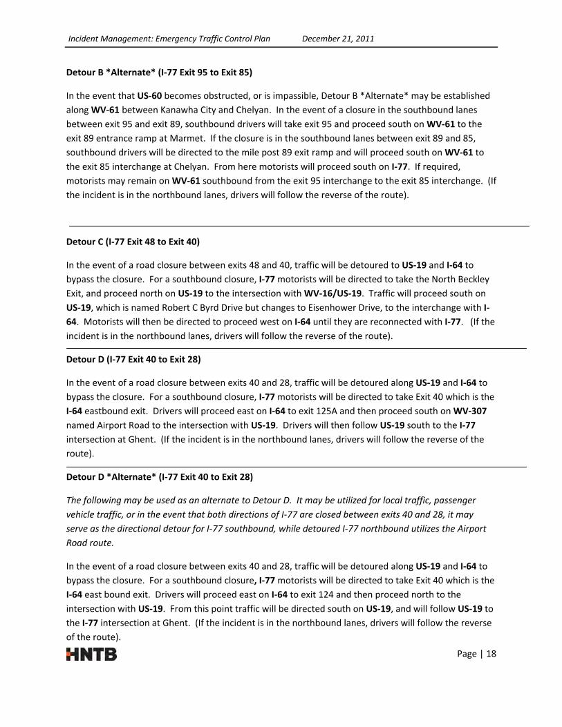
Detour B *Alternate* (I‐77 Exit 95 to Exit 85)
In the event that US‐60 becomes obstructed, or is impassible, Detour B *Alternate* may be established
along WV‐61 between Kanawha City and Chelyan. In the event of a closure in the southbound lanes
between exit 95 and exit 89, southbound drivers will take exit 95 and proceed south on WV‐61 to the
exit 89 entrance ramp at Marmet. If the closure is in the southbound lanes between exit 89 and 85,
southbound drivers will be directed to the mile post 89 exit ramp and will proceed south on WV‐61 to
the exit 85 interchange at Chelyan. From here motorists will proceed south on I‐77. If required,
motorists may remain on WV‐61 southbound from the exit 95 interchange to the exit 85 interchange. (If
the incident is in the northbound lanes, drivers will follow the reverse of the route).
Detour C (I‐77 Exit 48 to Exit 40)
In the event of a road closure between exits 48 and 40, traffic will be detoured to US‐19 and I‐64 to
bypass the closure. For a southbound closure, I‐77 motorists will be directed to take the North Beckley
Exit, and proceed north on US‐19 to the intersection with WV‐16/US‐19. Traffic will proceed south on
US‐19, which is named Robert C Byrd Drive but changes to Eisenhower Drive, to the interchange with I‐
64. Motorists will then be directed to proceed west on I‐64 until they are reconnected with I‐77. (If the
incident is in the northbound lanes, drivers will follow the reverse of the route).
Detour D (I‐77 Exit 40 to Exit 28)
In the event of a road closure between exits 40 and 28, traffic will be detoured along US‐19 and I‐64 to
bypass the closure. For a southbound closure, I‐77 motorists will be directed to take Exit 40 which is the
I‐64 eastbound exit. Drivers will proceed east on I‐64 to exit 125A and then proceed south on WV‐307
named Airport Road to the intersection with US‐19. Drivers will then follow US‐19 south to the I‐77
intersection at Ghent. (If the incident is in the northbound lanes, drivers will follow the reverse of the
route).
Detour D *Alternate* (I‐77 Exit 40 to Exit 28)
The following may be used as an alternate to Detour D. It may be utilized for local traffic, passenger
vehicle traffic, or in the event that both directions of I‐77 are closed between exits 40 and 28, it may
serve as the directional detour for I‐77 southbound, while detoured I‐77 northbound utilizes the Airport
Road route.
In the event of a road closure between exits 40 and 28, traffic will be detoured along US‐19 and I‐64 to
bypass the closure. For a southbound closure, I‐77 motorists will be directed to take Exit 40 which is the
I‐64 east bound exit. Drivers will proceed east on I‐64 to exit 124 and then proceed north to the
intersection with US‐19. From this point traffic will be directed south on US‐19, and will follow US‐19 to
the I‐77 intersection at Ghent. (If the incident is in the northbound lanes, drivers will follow the reverse
of the route).

Incident Management: Emergency Traffic Control Plan December 21, 2011
Page | 19
Detour E (I‐77 Exit 40 to Exit 9)
In the event of a road closure between exits 28 and 9, traffic will be detoured along I‐64, US‐219, and
US‐460 to bypass the closure. For a southbound closure, I‐77 motorists will be directed to take Exit 40
which is the I‐64 east bound exit. Drivers will proceed east on I‐64 to exit 169 and then proceed south
on US‐219 approximately 46 miles to the intersection with US‐460. Motorists will be directed west on
US‐460 and will continue on US‐460 to the intersection with I‐77. (If the incident is in the northbound
lanes, drivers will follow the reverse of the route).

HNTB CORPORATION
ENGINEERS ARCHITECTS PLANNERSNTB
DETOUR ROUTE
LEGEND
MP 59.0 (I-64) TO MP 48.0 (I-77)
DRIVE TIME - 2 HRS 15 MIN
DETOUR LENGTH - 130 MILESINCIDENT AREA (MP 85.0 TO 48.0)
PAGE 20
SUMMERSVILLE
NORTH BECKLEY
EXIT 48 (I-77)
BECKLEY
EXIT 57 (I-77)
TO I-79
TO I-77
EXIT 59 (I-64 TO I-77)
(I-77 TO I-79)
EXIT 104
DETOUR - A

HNTB CORPORATION
ENGINEERS ARCHITECTS PLANNERSNTB
DETOUR ROUTE
LEGEND
CEDAR GROVE
CHELYAN
EXIT 85
BELLE
MIDLAND TRAIL
EXIT 96
MP 96.0 TO MP 85.0
DRIVE TIME - 13 MINDETOUR LENGTH - 10 MILES
PAGE 21
INCIDENT AREA
DETOUR - B

HNTB CORPORATION
ENGINEERS ARCHITECTS PLANNERSNTB
DETOUR ROUTE
INCIDENT AREA
LEGEND
MP 48.0 TO MP 40.0
LEWISBURG
EXIT 40
SUMMERSVILLE
NORTH BECKLEY
EXIT 48
DRIVE TIME - 18 MINDETOUR LENGTH - 12 MILES
EISENHOWER DR.
BECKLEY
EXIT 124
PAGE 22
DETOUR - C

HNTB CORPORATION
ENGINEERS ARCHITECTS PLANNERSNTB
DETOUR ROUTE
INCIDENT AREA
LEGEND
FLAT TOP
GHENT
EXIT 28
I-64
EXIT 40
MP 40.0 (I-64) TO MP 28.0
DRIVE TIME - 21 MINDETOUR LENGTH - 18 MILES
BEAVER
EXIT 125A
PAGE 23
DETOUR - D

HNTB CORPORATION
ENGINEERS ARCHITECTS PLANNERSNTB
DETOUR ROUTE
LEGEND
MP 40.0 TO MP 9.0
DRIVE TIME - 2 HR 5 MINDETOUR LENGTH - 112 MILES
PRINCETON
EXIT 9
RONCEVERTE
LEWISBURG
EXIT 169
INCIDENT AREA (MP 28.0 TO 9.0)
PAGE 24
I-64
EXIT 40 (I-77 TO I-64)
DETOUR - E
Incident Management: Emergency Traffic Control Plan December 21, 2011
Page | 25
RecommendedDetourFacilityAdditionsandUpgrades
The detour routes as outlined above have been determined to be the most feasible alternative routes
for use in incident management. However, there are modifications, both from an operational and a
physical point of view, that would contribute to the safety and efficiency provided by these routes.
Operational modifications may involve either short‐term modifications or implementation of long‐term
changes. Upgrades to the physical aspects of temporary detour routes involve elements ranging from
maintenance obligations to permanent geometric improvements and facility additions. Suggestions for
operational modifications and physical upgrades are provided below.
OperationalAspects
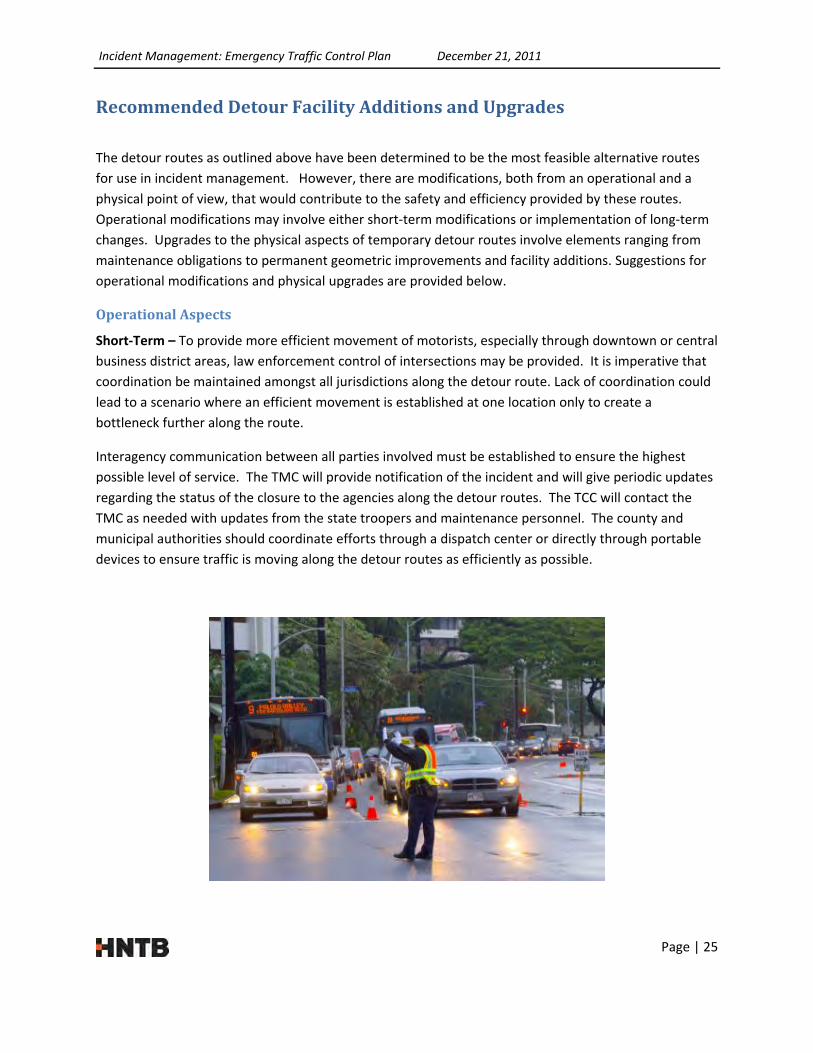
Short‐Term – To provide more efficient movement of motorists, especially through downtown or central
business district areas, law enforcement control of intersections may be provided. It is imperative that
coordination be maintained amongst all jurisdictions along the detour route. Lack of coordination could
lead to a scenario where an efficient movement is established at one location only to create a
bottleneck further along the route.
Interagency communication between all parties involved must be established to ensure the highest
possible level of service. The TMC will provide notification of the incident and will give periodic updates
regarding the status of the closure to the agencies along the detour routes. The TCC will contact the
TMC as needed with updates from the state troopers and maintenance personnel. The county and
municipal authorities should coordinate efforts through a dispatch center or directly through portable
devices to ensure traffic is moving along the detour routes as efficiently as possible.
Incident Management: Emergency Traffic Control Plan December 21, 2011
Page | 26
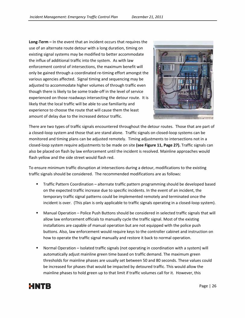
Long‐Term – In the event that an incident occurs that requires the
use of an alternate route detour with a long duration, timing on
existing signal systems may be modified to better accommodate
the influx of additional traffic into the system. As with law
enforcement control of intersections, the maximum benefit will
only be gained through a coordinated re‐timing effort amongst the
various agencies affected. Signal timing and sequencing may be
adjusted to accommodate higher volumes of through traffic even
though there is likely to be some trade‐off in the level of service
experienced on those roadways intersecting the detour route. It is
likely that the local traffic will be able to use familiarity and
experience to choose the route that will cause them the least
amount of delay due to the increased detour traffic.
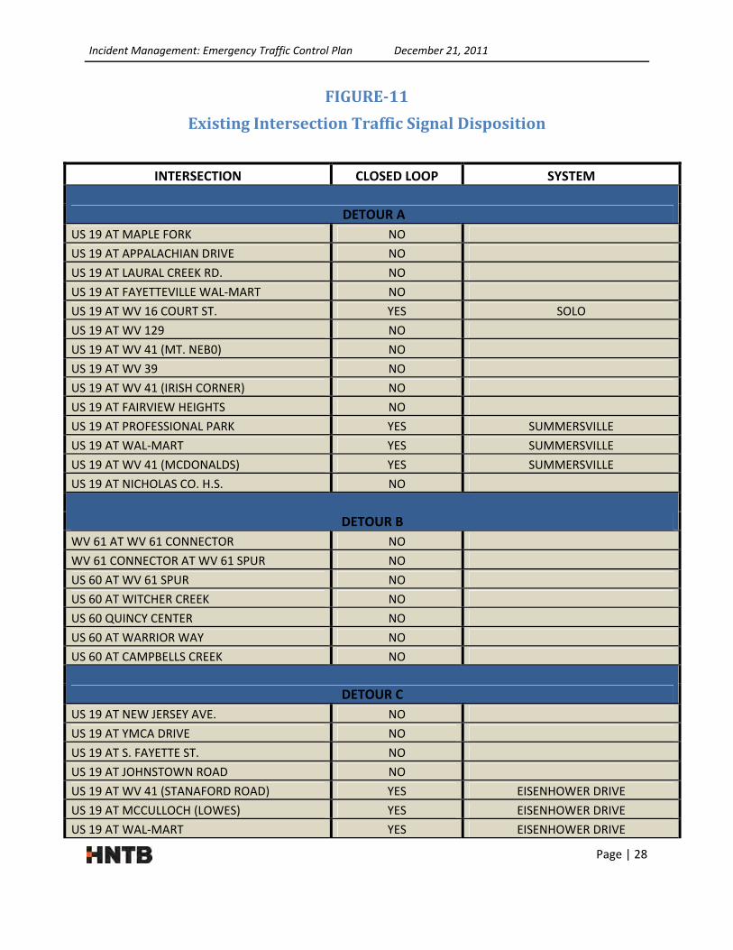
There are two types of traffic signals encountered throughout the detour routes. Those that are part of
a closed‐loop system and those that are stand alone. Traffic signals on closed‐loop systems can be
monitored and timing plans can be adjusted remotely. Timing adjustments to intersections not in a
closed‐loop system require adjustments to be made on site (see Figure 11, Page 27). Traffic signals can
also be placed on flash by law enforcement until the incident is resolved. Mainline approaches would
flash yellow and the side street would flash red.
To ensure minimum traffic disruption at intersections during a detour, modifications to the existing
traffic signals should be considered. The recommended modifications are as follows:
Traffic Pattern Coordination – alternate traffic pattern programming should be developed based
on the expected traffic increase due to specific incidents. In the event of an incident, the
temporary traffic signal patterns could be implemented remotely and terminated once the
incident is over. (This plan is only applicable to traffic signals operating in a closed‐loop system).
Manual Operation – Police Push Buttons should be considered in selected traffic signals that will
allow law enforcement officials to manually cycle the traffic signal. Most of the existing
installations are capable of manual operation but are not equipped with the police push
buttons. Also, law enforcement would require keys to the controller cabinet and instruction on
how to operate the traffic signal manually and restore it back to normal operation.
Normal Operation – Isolated traffic signals (not operating in coordination with a system) will
automatically adjust mainline green time based on traffic demand. The maximum green
thresholds for mainline phases are usually set between 50 and 80 seconds. These values could
be increased for phases that would be impacted by detoured traffic. This would allow the
mainline phases to hold green up to that limit if traffic volumes call for it. However, this

Incident Management: Emergency Traffic Control Plan December 21, 2011
Page | 27
modification comes with a risk of extended durations of signal phases in the event of a
secondary route traffic detection failure.
In urban areas having multi‐lane facilities, a combination of temporary traffic control and adjusted signal
timing may be used to redistribute direction lanes such that more lanes are available for the primary
direction of travel along a one‐direction detour. For example, a typical four‐lane roadway that normally
accommodates two northbound and two southbound lanes may be temporarily reconfigured to provide
one northbound and three southbound lanes assuming the primary movement is to the south.
Suspension of roadwork activities should be considered along roadways that comprise a long‐term
detour route. Efforts should be made to postpone work activities so that there is no additional
restriction on roadway capacity or efficiency. In the event that ongoing roadwork is of such a nature
that it is not possible to fully suspend operations, consideration must be given to performing those tasks
which result in the greatest impact to motorists during off‐peak hours.
Finally, enforcement of existing parking restrictions, or implementation of more stringent restrictions,
especially in downtown areas, along temporary detours, should be considered. Elimination of on‐street
parking in areas that cause potential conflicts with turning movements of large trucks and buses will
result in more efficient movement of motorists. A more comprehensive approach is to eliminate on‐
street parking in congested urban areas entirely. This method will not only provide additional clearance
for turning movements at intersections, but will also provide additional lane‐width clearance for large
trucks and busses – especially if a two‐way detour is initiated. Additionally, throughput speed will be
higher with the additional lateral clearances than with the restricted clearance resulting from parked
vehicles adjacent to a corridor. Positioning wrecker service vehicles along the detour route is also
recommended to help enforce parking restrictions, and to ensure quick response to immobilized
vehicles along the detour route.
Incident Management: Emergency Traffic Control Plan December 21, 2011
Page | 28
FIGURE‐11
ExistingIntersectionTrafficSignalDisposition
INTERSECTION CLOSED LOOP SYSTEM
DETOUR A
US 19 AT MAPLE FORK NO
US 19 AT APPALACHIAN DRIVE NO
US 19 AT LAURAL CREEK RD. NO
US 19 AT FAYETTEVILLE WAL‐MART NO
US 19 AT WV 16 COURT ST. YES SOLO
US 19 AT WV 129 NO
US 19 AT WV 41 (MT. NEB0) NO
US 19 AT WV 39 NO
US 19 AT WV 41 (IRISH CORNER) NO
US 19 AT FAIRVIEW HEIGHTS NO
US 19 AT PROFESSIONAL PARK YES SUMMERSVILLE
US 19 AT WAL‐MART YES SUMMERSVILLE
US 19 AT WV 41 (MCDONALDS) YES SUMMERSVILLE
US 19 AT NICHOLAS CO. H.S. NO
DETOUR B
WV 61 AT WV 61 CONNECTOR NO
WV 61 CONNECTOR AT WV 61 SPUR NO
US 60 AT WV 61 SPUR NO
US 60 AT WITCHER CREEK NO
US 60 QUINCY CENTER NO
US 60 AT WARRIOR WAY NO
US 60 AT CAMPBELLS CREEK NO
DETOUR C
US 19 AT NEW JERSEY AVE. NO
US 19 AT YMCA DRIVE NO
US 19 AT S. FAYETTE ST. NO
US 19 AT JOHNSTOWN ROAD NO
US 19 AT WV 41 (STANAFORD ROAD) YES EISENHOWER DRIVE
US 19 AT MCCULLOCH (LOWES) YES EISENHOWER DRIVE
US 19 AT WAL‐MART YES EISENHOWER DRIVE

Incident Management: Emergency Traffic Control Plan December 21, 2011
Page | 29
US 19 AT R.C. BYRD (WV 16) YES EISENHOWER DRIVE
US 19 AT BECKLEY PLAZA YES EISENHOWER DRIVE
US 19 AT INDUSTRIAL DRIVE YES EISENHOWER DRIVE
US 19 AT RALEIGH MALL YES EISENHOWER DRIVE
US 19 AT PROSPERITY ROAD NO
US 19 AT PROSPERITY CRANBERRY SCHOOL NO
US 19 AT CROSSROADS MALL NO
US 19 AT WV 16 RAMP (BRADLEY) NO
DETOUR D
US 19 AT WV 3 (SHADY SPRINGS) NO
US 19 AT WV 307 (BEAVER) NO
DETOUR E
US 219 AT GREENBRIER MALL NO
US 219 AT HOLT LANE NO
US 219 AT FOSTER STREET YES LEWISBURG CBD
US 219 AT US 60 YES LEWISBURG CBD
US 219 AT WAL‐MART YES LEWISBURG I/C
US 219 AT COLEMEN DRIVE YES LEWISBURG I/C
US 219 AT I‐64 WB RAMP YES LEWISBURG I/C
PhysicalAspects
While the detour routes identified in this plan are determined to be the roadways most capable of
handling the rerouted traffic, there are several areas in which further improvement should be made to
ensure successful traffic movement during a turnpike closure.
Additional detour facilities are recommended to increase traffic abatement capabilities and
consequently better accommodate the West Virginia Turnpike Patrons. This study has identified an area
around mile post 69.5 as a potential location for an additional removable concrete median barrier gate.
This area is located at the tangent section of roadway north of the Morton Rest Area. There are also
locations where a short detour connector road could be installed to provide emergency access to
secondary roads. There is an opportunity to add this type of improvement to the top of Flat Top
Mountain around MP 26. Here an existing access to a material storage area could be improved to
accommodate traffic detouring from the Turnpike onto US‐19.
Median cross‐overs, as previously discussed, are critical traffic abatement facilities for use in incident
management along the Turnpike. While all the cross‐overs listed are paved and capable of carrying
Incident Management: Emergency Traffic Control Plan December 21, 2011
Page | 30
traffic under temporary detour conditions, there is room for improvement. Many cross‐overs could
benefit from the addition of acceleration and deceleration lanes. During an incident management
scenario, this additional pavement width would also improve turning movements onto and off of the
cross‐overs. Secondly, more comprehensive delineation at median cross‐overs would provide better
guidance to motorists considering that these abatement facilities would potentially be put to use in less
than desirable weather conditions. Yellow flexible plastic delineator posts should be installed per
WVDOH Standard 661.2.5‐“Delineators” at each median cross‐over to delineate a clear path for
motorists.
With respect to the alternative detour routes, all intersections lacking adequate turning movements to
accommodate large trucks (as well as all other traffic typically traveling the interstate) should be
considered high priority when developing statewide roadway improvement plans. Similarly, all areas
along the detour routes containing deteriorated asphalt surface conditions should be considered as
priority for repair and upgrade in the annual paving program. Placing emphasis on the upgrade and
upkeep of these detour routes will allow for the safest and most efficient movement of motorists under
incident management situations.
Along the same lines, the roadways designated as detour routes for incident management must be
granted priority status in terms of snow removal and roadway treatment. Not only will this emphasis
improve the efficiency as far as through‐put speed in general, but it will also serve to reduce the
potential for secondary crashes and subsequent traffic delays on detour routes. During weather related
events, careful coordination must be conducted by all agencies to ensure that proposed detour routes
are in proper condition for safe travel prior to traffic being diverted onto them. Once Turnpike traffic is
occupying the secondary roadway system, snow and ice removal will become more difficult. If feasible,
the Parkways Authority will assist the DOH with snow removal on the WV Turnpike detour routes, such
as US‐19, US‐60 and I‐64.
The detour routes established within this plan are the most feasible of the options available for
diversion of traffic during an incident or weather event. However, there are operational and physical
characteristics that must be given attention in order for the incident management plan to function at
the highest level possible. Some of these modifications require little effort to implement, such as the
short‐term operational changes, while others will require assistance from program planning at the state
level to be implemented.
RecommendedRevisionstotheTurnpikeDetourManual
It is recommended that the Turnpike Detour Manual be updated to reflect only the approved detours
outlined in this report. Likewise, all turnpike closure and detour guidance including facilities, policies,
etc., should be incorporated into the revised detour manual. The Turnpike Detour Manual should also
refer to this document regarding road closure protocols and the roles of the various Parkways Personnel
as related to emergency traffic control.

Incident Management: Emergency Traffic Control Plan December 21, 2011
Page | 31
DetourSignage
PermanentDetourSigns
To lessen the occurrence of secondary incidents resulting from an incident causing a roadway blockage,
effective signing must be in place to guide motorists away from the major conflict point and onto one of
the predetermined alternative routes. The sole reason for installation of the trailblazer assemblies is to
provide guidance to motorists who are being directed to use a route that they may be unfamiliar with or
that is more complicated than the intended route to their destination. As such, the detour signing must
command attention of the motorists and convey clear direction as to what action they are to take and
when/where it should be taken. To achieve the most desirable results, it is imperative that the
permanently installed detour signing abide by the general requirements of the Manual on Uniform
Traffic Control Devices (MUTCD). More specifically, consideration must be given to providing an
appropriate color scheme (see recommended color scheme below), establishing proper placement along
a given route, and ensuring correct installation in regards to mounting height and lateral offset.
The legend and border of the sign panels used to delineate the temporary detour route should be white,
and should be placed on a black background. This color combination is easily recognizable and does not
introduce potential confusion due to other warning, guidance, or regulatory signs. The letter
designation indicating the route should be displayed in the center of the panel with the word “DETOUR”
displayed just below the letter designation. Additionally, a directional arrow panel similar to type M6‐1,
M6‐2, or M6‐3 described in the Manual on Uniform Traffic Control Devices is to be placed below the
detour sign designation and must abide by conventional signing practice as to which arrow shape is to
be used on a specific assembly. See Sign Exhibits below for a suggested panel layout:
Interstate/Primary Route Sign Exhibit ‐ Suggested Sign Panel Layout

Incident Management: Emergency Traffic Control Plan December 21, 2011
Page | 32
Secondary Route Sign Exhibit ‐ Suggested Sign Panel Layout
The permanent detour signs must be installed at key locations along the route. There are two critical
aspects to consider when identifying the appropriate installation locations:
‐ Specific locations at which a motorist must make a decision to leave one roadway and begin
travel on another to continue on the intended detour route or pass through an intersection
with another roadway and remain on their current path to complete the detour. These
decision points are located at intersections with major crossroads at which detour signing
must be established to provide advance notice of the required action as well as directional
guidance at the intersection point. Installation spacing for both the advance notice and
directional guidance should follow specifications established by the MUTCD.
‐ Confirmation signing must be erected both immediately following decision points as well as
at regular intervals in between these points. As with conventional signing practice, it is
critical to provide motorists with confirmation that they have taken an action that meets
their intended results. Similarly, periodic confirmation must be established along the detour
route in areas where major intersections are sparsely located. Confirmation signs should be
placed concurrent with existing route confirmation signs, potentially as part of the same
assembly. Additional signs may be needed in areas of high congestion such as downtowns
and central business districts.
Installation of permanent detour signing should be done as a joint venture between the Division of
Highways and the Parkways Authority. Additionally, the Authority will conduct quarterly checks of all
permanent detour signs and provide repair or replacement services as needed.

Incident Management: Emergency Traffic Control Plan December 21, 2011
Page | 33
DynamicMessageSigns
In regard to incident management, the primary function of the dynamic message signs (DMS) is to
provide advanced warning and up‐to‐date information regarding a roadway closure or anticipated
motorist delay as well as speed limit advisories. DMSs may also be used to provide alternate route
detour information. In order to convey clear direction and effective messages, the guidelines for
message generation contained in Chapter 2L of the 2009 MUTCD must be adhered to. The figure below
shows an example of such use of a DMS.
DMS Messaging for Detour Guidance
The general operational considerations as prescribed in the Traffic Abatement portion of this report
apply to DMS use for alternate route information dissemination as well. As with all DMS operation,
coordination with bordering agencies (specifically the WVDOH and VDOT) must be ensured to provide
the most effective advance warning of the alternate routes and specific route guidance. This is currently
being accomplished through the integration of the TCC and the WVDOH TMC, and the TMC’s
communication with VDOT.
Operation
Resources
The Turnpike Management has identified a need for approximately (16) maintenance employees to be
present to execute a removable concrete median barrier gate opening and (12) to be present for all
other types of abatement facilities. Included in the (16) employees are individuals setting up warning
and detour signs, closing exits, and setting up traffic control at the barrier gates, as well as physically
opening the gate. Maintenance employees will also need to be available for flagging in the area of the

Incident Management: Emergency Traffic Control Plan December 21, 2011
Page | 34
removable concrete median barrier gates; both for traffic that has been stopped due to the incident and
for stopping traffic in the opposite direction. The Turnpike has also conveyed an equipment need of one
(1) end‐loader, two (2) pick‐up trucks, cones and barricades for traffic control, and temporary warning
and detour signs for accident clean‐up and preparation of abatement facilities. A number of PCMS will
also be required to provide situational guidance to motorists, especially while implementing a
temporary speed reduction.
In addition to WV Turnpike employees, the WV State Police will be asked to assist in the traffic diversion
and traffic control. The state troopers will also maintain an open shoulder throughout the duration of
the closures to permit emergency vehicles, tow services, and maintenance crews to access the incident
area. Permanent signs indicating that shoulders shall remain clear during an incident should be added
to all Turnpike entrance ramps.
Training
It is recommended that maintenance crews be trained annually on the implementation of Turnpike
closures, and specifically on traffic control measures for abatement facilities and the mechanics of
opening and closing the removable concrete median barrier gates. The training should include set‐up of
traffic control at each type of abatement facility. The training should also include hands‐on removal and
reinstallation of the barrier gates by the maintenance crews, and should be held at different barrier gate
sites from year to year. The Turnpike General Engineering Consultant will mark traffic control locations
at removable concrete median barrier gates prior to training. It is recommended that training occur
prior to the winter season, when an incident is most likely to occur.
It is also recommended that an annual training session be held on interagency coordination in the event
of a Turnpike closure. This training should include the WV Parkways Authority (decision makers and
maintenance employees), WVDOH (TMC Operators, Traffic Engineering Staff, and Maintenance
Personnel), Federal Highway Administration, and other state and local agencies deemed appropriate.
This training should cover the Standard Operating Procedure (SOP) of a Turnpike closure and traffic
abatement, and should outline the roles of each agency during the event. Also, during this training
session, a mock scenario should be presented and the various agencies should be asked to describe their
response and provide a timeline of their actions. These training exercises should include various types
of accidents (hazard materials, lost loads, etc.). These discussions should be mediated by an appointed
authority with the WVDOH and will be documented and published and distributed to the participants.
RolesofParkwaysPersonnel
SectionForeman
The Section Foreman, along with the State Police, is responsible for identifying road closures with
potential durations greater than two hours, and relaying information regarding delays or closures to the
TCC. The Foreman will coordinate the efforts of the maintenance crews to establish temporary detours,
set‐up traffic control devices, and prepare abatement facilities for use. The Foreman will continue to

Incident Management: Emergency Traffic Control Plan December 21, 2011
Page | 35
provide updates to the TCC regarding the status of the closures. In the event that the Section Foreman
is unavailable, the Roadway Manager will assume the duties of the Section Foreman.
StateTrooperSupervisor
The State Trooper Supervisor (Sergeant or higher), along with the Section Foreman, will assess the
closure duration and if it is warranted, make the decision to abate the stopped traffic. The Trooper will
also assist in traffic directing measures during the closure and detour, and keep the shoulders open to
allow emergency crews, towing services, and turnpike maintenance crews to access the scene of the
incident.
MaintenanceCrew
The Maintenance Crew reports to Section Foreman for assignments during the call‐out procedure and
provides updates of progress to the Foreman during the operations. The maintenance crews will set up
detour and road closure signs, place temporary cones, flag traffic, as well as manually open the barrier
gates as directed by the Foreman. The maintenance crews will also assist in the cleanup of debris and
the repair of any roadside safety features damaged during an incident.
TurnpikeControlCenter(TCC)
The TCC relays information regarding the status of the road closure to the various Parkways employees,
the WVDOH, and the towing services. The TCC also implements the maintenance crew call‐out
procedure when directed. In addition to notifying WV Parkways employees, the TCC will also notify
motorists of the incident and provide information regarding closure durations and detour routes
through the DMS(s).
Legislation
Policies addressing obstruction of traffic following an accident, typically referred to as “Quick Clear”, or
“Steer and Clear”, have been adopted by many states in recent years as a way of preventing additional
accidents and maintaining traffic movement through the accident site. The 2009 edition of the Manual
of Uniform Traffic Control Devices provides the following guidance on this topic: Chapter 6I.04 “When a
minor traffic incident blocks a travel lane, it should be removed from that lane to the shoulder as
quickly as possible”. These policies are typically applicable to non‐injury or minor‐injury accidents. This
edition also provides a standard sign (R16‐4) directing drivers to move vehicles from travel lanes in the
event of a fender bender.
The current WV Code 17C‐4 “Accidents” addresses unnecessary vehicular obstruction following an
accident. Code 17C-4-2 states “The driver of any vehicle involved in a crash resulting only in damage to a vehicle which is driven or attended by any person shall immediately stop such vehicle at the scene of such crash or as close thereto as possible…Every such stop shall be made without obstructing traffic more than necessary”. While the direction is to not obstruct

Incident Management: Emergency Traffic Control Plan December 21, 2011
Page | 36
traffic more than necessary, there is no emphasis on the timing of removing the obstruction. It is
recommended that the code be amended to include language indicating that maintaining traffic flow is a
priority and obstructions shall be removed as soon as possible. The code should also be revised to
provide direction to first responders as well as drivers. Language should be clear that public safety is
paramount and adjacent traffic shall remain unobstructed to the extent possible in an effort to prevent
secondary accidents resulting from stopped traffic. It is also recommended that the WVDOT propose
legislation to keep roadway shoulders clear of parked vehicles during an emergency, to allow emergency
vehicles access to accident sites.
ExampleLegislation
The state of Florida has written into law the following with regard to clearing disabled vehicles:
Florida Statute 316.071, entitled “Disabled vehicles obstructing traffic”
Whenever a vehicle is disabled on any street or highway within the state or for any reason obstructs the regular flow of traffic, the driver shall move the vehicle so as to not obstruct the regular flow of traffic or, if he or she cannot move the vehicle alone, solicit help and move the vehicle so as not to obstruct the regular flow of traffic. Any person failing to comply with the provisions of this section shall be cited for a nonmoving violation, punishable as provided in chapter 318.
A similar law could be modified to include any vehicle involved in a collision, and could be extended to
accident first responders, making maintenance of traffic flow one of their top priorities.
Contacts
WV Homeland Security and Emergency Management Agency 304-558-5380 Bldg. 1, Rm. EB-80 Fax: 304-344-4538 1900 Kanawha Blvd, East Charleston, WV 25305 Email: [email protected] (Jimmy Gianato, Director) Web: http://www.wvdhsem.gov/ WV State Police - Troop 7 Command (Kanawha County) 304-926-1900 P.O. Box 1469 Fax: 304-926-1909 Charleston, WV 25325-1469 Web: http://www.wvstatepolice.com/ WV State Police – Beckley Troop 6 (Raleigh County) 304-256-6700 105 Pinecrest Drive Fax: 304-256-6983 Beckley, WV 25801-5349 Web: http://www.wvstatepolice.com/

WV Transportation Management Center
Bldg 5 Rm 362 1900 Kanawha Blvd East Charleston,
WV 25305 Web: [email protected] (Jim Lambert,
Manager)
WV Parkways Authority
P.O. Box 1469 Charleston, WV
25325-1469 Email:
[email protected] Web:
http://www.wvturnpike.com
WV Parkways Authority Directory
Mark Miller, Section-1 Foreman
Curtis Redden, Section-2 Foreman
James Embrey, Section-3 Foreman
Jim Meadows, Highway Production Manager
Dave Pugh, Roadway Manager
Les Ball, Highway Maint. Program Manager
304-558-3028
Fax: 304-558-3246
304-926-1900
Fax: 304-926-1909
Office: 304-787-4519
Office: 304-256-6927
Office: 304-595-4542
Office: 304-256-6680
Office: 304-256-6680
Office: 304-256-6680

Ron Hamilton, Maintenance Engineer Office: 304-256-6680
Carl Williams, Safety Officer Office: 304-256-6890
Greg Barr, General Manager Office: 304-926-1900 (Ext 302)
Tyrone Gore, Director of Operations Office: 304-926-1900 (Ext 310)
Turnpike Control Center Office: 304-926-1908
WV Department of Transportation 304-558-0444 Office of Secretary of Transportation Fax:
304-558-1004 Bldg. 5, Rm. A-109 1900 Kanawha Blvd, East Charleston, WV 25305 Email:
[email protected] Web: http://www.transportation.wv.gov/Pages/default.aspx
WVDOH District Directory
District 1 (Kanawha County) – John McBrayer, District Manager 304-558-3001
District 9 (Fayette County) – Don Beals, Acting District Manager 304-647-7450
District 10 (Raleigh and Mercer Counties) – Thomas Camden, Acting District Manager
304-487-5228
District 7 (Barbour, Braxton, Gilmer, Lewis, Upshur, & Webster Counties) – Ron Hooton,
District Engineer 304-269-0400

Incident Management: Emergency Traffic Control Plan December 21, 2011
Page | 39
Kanawha County Emergency Communication Center 304-348-8111
Kanawha County Emergency Services Directory
Kanawha County Medical Transport 304-342-1107
Kanawha County Ambulance and Fire Services 304-357-0191
Kanawha County Sheriff’s Department 304-357-0200
WV State Emergency Spill Notification 800-642-3074
Fayette County Office of Emergency Services 304-574-1610
Fayette County Emergency Services Directory
EMS Business Office General Ambulance 304-465-8700
Fayette County Dispatch Center 304-574-1610
Fayette County Sheriff - Fayetteville 304-574-4304
WV State Emergency Spill Notification 800-642-3074
Raleigh County Emergency Operations Center 304-255-0911
Raleigh County Emergency Services Directory
General Ambulance Service 304-252-5800
Raleigh County Dispatch Center 304-255-9121
Raleigh County Sheriff 304-255-9300
WV State Emergency Spill Notification 800-642-3074
KANAWHA COUNTY
FAYETTE COUNTY
RALEIGH COUNTY

Incident Management: Emergency Traffic Control Plan December 21, 2011
Page | 40
Mercer County Emergency Communication Center 304-425-8911
Mercer County Emergency Services Directory
Princeton Rescue 304-425-3914
Mercer County Sheriff 304-487-8364
WV State Emergency Spill Notification 800-642-3074
Beckley Fire Department 304-256-1780 Kevin B. Taylor, Fire Chief Fax: 304-256-1792 310 Third Avenue Beckley, WV 25801 Email: [email protected] Beckley City Police Department 304-256-1710 Timothy P. Deems, Chief of Police Fax: 304-256-1736 340 Prince Street Beckley, WV 25801 Email: [email protected] Jan-Care Ambulance Service 304-255-1588 117 South Fayette Street Beckley, WV 25801 HNTB Corporation 304-757-0888 #3 Mission Way Fax: 304-757-6639 Scott Depot, WV 25560
CITY OF BECKLEY
MERCER COUNTY
WVPA GENERAL ENGINEERING CONSULTANT


