02/06 ID# M88111411© COPYRIGHT 2006 by SPALDING
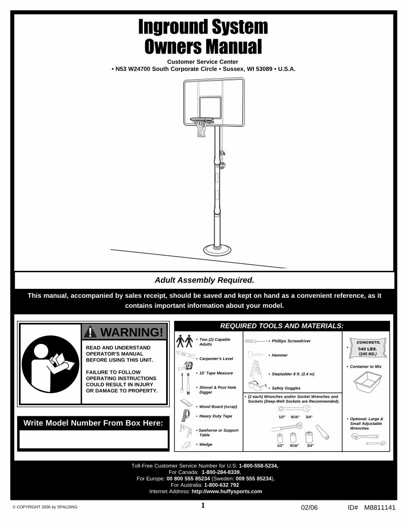
Inground SystemOwners Manual
Customer Service Center• N53 W24700 South Corporate Circle • Sussex, WI 53089 • U.S.A.
• Two (2) CapableAdults
• Carpenter’s Level
• 15’ Tape Measure
• Shovel & Post HoleDigger
• Wood Board (scrap)
• Heavy Duty Tape
• Sawhorse or SupportTable
• Wedge
•
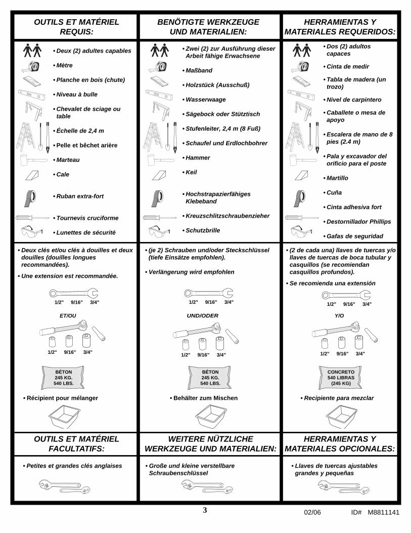
• Container to Mix
• (2 each) Wrenches and/or Socket Wrenches andSockets (Deep-Well Sockets are Recommended).
1/2" 9/16" 3/4" • Optional: Large &Small AdjustableWrenches
1/2" 9/16" 3/4"
REQUIRED TOOLS AND MATERIALS:
• Phillips Screwdriver
• Hammer
• Stepladder 8 ft. (2.4 m)
• Safety Goggles
Toll-Free Customer Service Number for U.S: 1-800-558-5234,For Canada: 1-800-284-8339,
For Europe: 00 800 555 85234 (Sweden: 009 555 85234),For Australia: 1-800-632 792
Internet Address: http://www.huffysports.com
READ AND UNDERSTANDOPERATOR'S MANUALBEFORE USING THIS UNIT.
FAILURE TO FOLLOWOPERATING INSTRUCTIONSCOULD RESULT IN INJURYOR DAMAGE TO PROPERTY.
WARNING!
Write Model Number From Box Here:
This manual, accompanied by sales receipt, should be saved and kept on hand as a convenient reference, as it
contains important information about your model.
Adult Assembly Required.

2ID# M8811141 02/06
AVERTISSEMENT!WARNUNG!
¡ADVERTENCIA!
LISEZ LE MODE D'EMPLOI AVANT D'UTILISER CE SYSTÈME
SOUS PEINE D'ENCOURIR DESBLESSURES OU DES DÉGÂTSMATÉRIELS.
DAS BENUTZERHANDBUCH VORGEBRAUCH DIESES PRODUKTSSORGFÄLTIG DURCHLESEN.
EIN MISSACHTEN DIESER BETRIEBSANLEITUNG KANN VERLETZUNGEN ODER SACHSCHÄDEN ZUR FOLGE HABEN.
LEA Y ENTIENDA EL MANUAL DELOPERADOR ANTES DE USAR ESTAUNIDAD.
SI NO SE SIGUEN LAS INSTRUCCIONES DE OPERACIÓN SEPODRÍA OCASIONAR UNA LESIÓN ODAÑOS A LA PROPIEDAD.
Numéro sans frais du service clientèle (États-Unis) : 1-800-558-5234 ; Canada : 1-800-284-8339 ; Europe : 00 800 555 85234
(Suède : 009 555 85234), Pour l'Australie : 1-800-333 061 - Site Internet : http://www.huffysports.com
Gebührenfreie Kundendienstnummer für Anrufer in den USA: 1-800-558-5234 Für Anrufer in Kanada: 1-800-284-8339 Für
Anrufer in Europa: 00 800 555 85234 (Schweden: 009 555 85234) Für Australien: 1-800-333.061 - Internet-Adresse:
http://www.huffysports.com
Número telefónico gratuito de servicio al cliente en EE. UU.: 1-800-558-5234, para Canadá: 1-800-284-8339, para Europa: 00
800 555 85234 (Suecia: 009 555 85234), para Australia: 1-800-333 061 - Dirección en Internet: http://www.huffysports.com
Inscrivez ici le numéro de modèle qui apparaît sur la boîte:
Die Modellnummer vom Verpackungskarton hier eintragen:
Escriba aquí el número de modelo que viene en la caja:
Viereckiges Stangensystem Benutzerhandbuch
Kundendienstzentrale• N53 W24700 South Corporate Circle • Sussex, WI 53089 • U.S.A.
Sistema de fijación en el pisoManual del propietario
Centro de Servicio al Cliente• N53 W24700 South Corporate Circle • Sussex, WI 53089 • EE.UU.
Système de poteau carré Manuel de l’utilisateur
Service clientèle• N53 W24700 South Corporate Circle • Sussex, WI 53089 • É.-U.
Ce manuel, accompagné du justificatif d'achat, devra être conservé pour
référence ultérieure, dans la mesure où il contient des informations
importantes sur votre modèle.
Diese Anleitung sollte zusammen mit dem Kaufbeleg griffbereit
aufbewahrt werden, da sie wichtige Informationen über Ihr Modell enthält.
Il presente manuale, accompagnato dallo scontrino, deve essere
conservato e tenuto a portata di mano come documento di facile
consultazione, in quanto contiene informazioni importanti su questo
modello.
Assemblage exclusivement réservé à un adulte.
Zusammenbau nur durch Erwachsene ALLE Verpackungsmaterialiensofort wegwerfen.
Il montaggio va eseguito da persone adulte.
02/06 ID# M88111413
OUTILS ET MATÉRIELREQUIS:
• Deux clés et/ou clés à douilles et deuxdouilles (douilles longuesrecommandées).
• Une extension est recommandée.
• Petites et grandes clés anglaises
OUTILS ET MATÉRIELFACULTATIFS:
• Deux (2) adultes capables
• Mètre
• Planche en bois (chute)
• Niveau à bulle
• Chevalet de sciage outable
• Échelle de 2,4 m
• Pelle et bêchet arière
• Marteau
• Cale
• Ruban extra-fort
• Tournevis cruciforme
• Lunettes de sécurité
• Récipient pour mélanger
BENÖTIGTE WERKZEUGEUND MATERIALIEN:
• (je 2) Schrauben und/oder Steckschlüssel(tiefe Einsätze empfohlen).
• Verlängerung wird empfohlen
• Große und kleine verstellbareSchraubenschlüssel
WEITERE NÜTZLICHEWERKZEUGE UND MATERIALIEN:
• Zwei (2) zur Ausführung dieserArbeit fähige Erwachsene
• Maßband
• Holzstück (Ausschuß)
• Wasserwaage
• Sägebock oder Stütztisch
• Stufenleiter, 2,4 m (8 Fuß)
• Schaufel und Erdlochbohrer
• Hammer
• Keil
• HochstrapazierfähigesKlebeband
• Kreuzschlitzschraubenzieher
• Schutzbrille
HERRAMIENTAS YMATERIALES REQUERIDOS:
• (2 de cada una) llaves de tuercas y/ollaves de tuercas de boca tubular ycasquillos (se recomiendancasquillos profundos).
• Se recomienda una extensión
• Llaves de tuercas ajustablesgrandes y pequeñas
HERRAMIENTAS YMATERIALES OPCIONALES:
• Dos (2) adultoscapaces
• Cinta de medir
• Tabla de madera (untrozo)
• Nivel de carpintero
• Caballete o mesa deapoyo
• Escalera de mano de 8pies (2.4 m)
• Pala y excavador delorificio para el poste
• Martillo
• Cuña
• Cinta adhesiva fort
• Destornillador Phillips
• Gafas de seguridad
ET/OU
1/2" 9/16" 3/4"
UND/ODER Y/O
1/2" 9/16" 3/4"
1/2" 9/16" 3/4" 1/2" 9/16" 3/4"
1/2" 9/16" 3/4"1/2" 9/16" 3/4"
BÉTON245 KG.540 LBS.
• Behälter zum Mischen
BÉTON245 KG.540 LBS.
• Recipiente para mezclar
CONCRETO540 LIBRAS
(245 KG)

4ID# M8811141 02/06
SA
FE
TY
INS
TR
UC
TIO
NS
Mos
t inj
urie
s ar
e ca
used
by
mis
use
and/
or n
ot fo
llow
ing
inst
ruct
ions
.U
se c
autio
n w
hen
usin
g th
is s
yste
m.
•If
usi
ng
a la
dd
er d
uri
ng
ass
emb
ly, u
se e
xtre
me
cau
tio
n.
•T
wo
(2)
cap
able
ad
ult
s ar
e re
com
men
ded
fo
r th
is o
per
atio
n.
•S
eat
the
po
le s
ecti
on
s p
rop
erly
. Fai
lure
to
do
so
co
uld
allo
w t
he
po
lese
ctio
ns
to s
epar
ate
du
rin
g p
lay.
•B
efo
re d
igg
ing
, co
nta
ct u
tilit
y co
mp
any
to lo
cate
un
der
gro
un
d p
ow
erca
ble
s, g
as, a
nd
wat
er li
nes
. En
sure
th
ere
are
no
ove
rhea
d p
ow
erlin
es w
ith
in 2
0 ft
. (7
m)
rad
ius
of
po
le lo
cati
on
.•
Clim
ate,
co
rro
sio
n, e
xces
sive
use
, or
mis
use
co
uld
res
ult
in s
yste
mfa
ilure
.•
If t
ech
nic
al a
ssis
tan
ce is
req
uir
ed, c
on
tact
Cu
sto
mer
Ser
vice
.•
Min
imu
m o
per
atio
nal
hei
gh
t is
6'6
" (1
.98
m)
to t
he
bo
tto
m o
fb
ackb
oar
d.
•T
his
eq
uip
men
t is
inte
nd
ed f
or
ho
me
recr
eati
on
al u
se o
nly
an
d N
OT
exce
ssiv
e co
mp
etit
ive
pla
y.•
Rea
d a
nd
un
der
stan
d t
he
war
nin
g la
bel
aff
ixed
to
po
le.
•T
he
life
of
you
r b
aske
tbal
l po
le d
epen
ds
on
man
y co
nd
itio
ns.
T
he
clim
ate,
pla
cem
ent
of
the
po
le, t
he
loca
tio
n o
f th
e p
ole
, exp
osu
re t
oco
rro
sive
s su
ch a
s p
esti
cid
es, h
erb
icid
es, o
r sa
lts
are
all i
mp
ort
ant.
•A
du
lt s
up
ervi
sio
n is
rec
om
men
ded
wh
en a
dju
stin
g h
eig
ht.
•S
erio
us
inju
ry c
ou
ld o
ccu
r if
tee
th/f
ace
com
e in
co
nta
ct w
ith
bac
kbo
ard
, net
, or
rim
.
FA
ILU
RE
TO
FO
LL
OW
TH
ES
E S
AF
ET
Y IN
ST
RU
CT
ION
S M
AY
RE
SU
LT
IN S
ER
IOU
SIN
JUR
Y, P
RO
PE
RT
Y D
AM
AG
E A
ND
WIL
L V
OID
WA
RR
AN
TY
.
Ow
ner
mu
st e
nsu
re t
hat
all
pla
yers
kn
ow
an
d f
ollo
w t
hes
e ru
les
for
safe
op
erat
ion
of
the
syst
em.
To
en
sure
saf
ety,
do
no
t at
tem
pt
to a
ssem
ble
th
is s
yste
m w
ith
ou
t fo
llow
ing
th
ein
stru
ctio
ns
care
fully
. P
rop
er a
nd
co
mp
lete
ass
emb
ly,
use
an
d s
up
ervi
sio
n i
ses
sen
tial
fo
r p
rop
er o
per
atio
n a
nd
to
red
uce
th
e ri
sk o
f ac
cid
ent
or
inju
ry.
A h
igh
pro
bab
ility
of
seri
ou
s in
jury
exi
sts
if t
his
sys
tem
is
no
t in
stal
led
, m
ain
tain
ed,
and
op
erat
ed p
rop
erly
.Ch
eck
enti
re b
ox
and
insi
de
all p
acki
ng
mat
eria
l fo
r p
arts
an
d/o
rad
dit
ion
al in
stru
ctio
nal
mat
eria
l. B
efo
re b
egin
nin
g a
ssem
bly
, rea
d t
he
inst
ruct
ion
san
d id
enti
fy p
arts
usi
ng
th
e h
ard
war
e id
enti
fier
an
d p
arts
list
in t
his
do
cum
ent.
CO
NS
IGN
ES
DE
SÉ
CU
RIT
É
La p
lupa
rt d
es b
less
ures
son
t cau
sées
par
une
util
isat
ion
impr
opre
et/o
u le
non
-res
pect
des
inst
ruct
ions
.S
oyez
pru
dent
lors
que
vous
util
isez
ce
syst
ème.
•S
i vo
us
uti
lisez
un
e éc
hel
le e
n c
ou
rs d
e m
on
tag
e, s
oye
z ex
trêm
emen
t p
rud
ent.
•Il
est
reco
mm
and
é d
e s’
y p
ren
dre
à d
eux
(2)
(ad
ult
es)
po
ur
réal
iser
cet
teo
pér
atio
n.
•E
mb
oît
ez c
orr
ecte
men
t le
s se
ctio
ns
de
po
teau
. Elle
s ri
squ
ent
sin
on
de
sed
ébo
îter
en
co
urs
de
jeu
.•
Ava
nt
de
creu
ser,
co
nta
ctez
les
fou
rnis
seu
rs d
'éle
ctri
cité
, gaz
et
eau
po
ur
situ
er le
s câ
ble
s d
'alim
enta
tio
n e
t le
s co
nd
uit
es d
e g
az e
t d
'eau
en
fou
is.
Ass
ure
z-vo
us
qu
'au
cun
e lig
ne
aéri
enn
e d
'éle
ctri
cité
ne
se t
rou
ve d
ans
un
rayo
n d
e 7
m d
e l'e
mp
lace
men
t d
u p
ote
au.
•L
es c
on
dit
ion
s cl
imat
iqu
es, l
a co
rro
sio
n, u
ne
uti
lisat
ion
exc
essi
ve o
u u
ne
mau
vais
e u
tilis
atio
n r
isq
uen
t d
e p
rovo
qu
er la
pan
ne
du
sys
tèm
e.•
Po
ur
tou
te a
ssis
tan
ce t
ech
niq
ue,
co
nta
ctez
le s
ervi
ce c
lien
tèle
.•
La
hau
teu
r m
inim
ale
d'u
tilis
atio
n e
st d
e 1,
98 m
(6'
6")
jusq
u'à
la b
ase
du
pan
nea
u.
•C
e m
atér
iel e
st r
éser
vé à
un
bu
t ré
créa
tif
à d
om
icile
et
NO
N P
AS
à u
n je
uex
trêm
emen
t co
mp
étit
if.
•L
isez
et
com
pre
nez
l'ét
iqu
ette
d'a
vert
isse
men
t fi
xée
au p
ote
au.
•L
a d
uré
e d
e vi
e d
e vo
tre
po
teau
de
bas
ket-
bal
l dép
end
de
bie
n d
es f
acte
urs
. Le
clim
at, l
a p
osi
tio
n d
u p
ote
au, s
on
em
pla
cem
ent,
so
n e
xpo
siti
on
à d
es a
gen
tsco
rro
sifs
tel
s q
ue
des
pes
tici
des
, des
her
bic
ides
ou
des
sel
s so
nt
tou
s d
esfa
cteu
rs im
po
rtan
ts.
•L
a su
per
visi
on
d'u
n a
du
lte
est
reco
mm
and
ée p
ou
r le
rég
lag
e d
e la
hau
teu
r.•
Ris
qu
e d
e b
less
ure
s g
rave
s si
les
den
ts o
u le
vis
age
vien
nen
t h
eurt
er le
pan
nea
u, l
e ce
rcea
u o
u le
file
t.
SU
IVE
Z C
ES
CO
NS
IGN
ES
DE
SÉ
CU
RIT
É S
OU
S P
EIN
E D
E P
RO
VO
QU
ER
DE
SB
LE
SS
UR
ES
GR
AV
ES
, DE
S D
ÉG
ÂT
S M
AT
ÉR
IEL
S E
T L
'AN
NU
LA
TIO
N D
E L
AG
AR
AN
TIE
..
Le
pro
pri
étai
re d
oit
s'a
ssu
rer
qu
e to
us
les
jou
eurs
co
nn
aiss
ent
et s
uiv
ent
ces
règ
les
d'u
tilis
atio
n s
ûre
du
sys
tèm
e.
Par
m
esu
re
de
sécu
rité
, n
'ess
ayez
p
as
de
mo
nte
r ce
sy
stèm
e sa
ns
suiv
resc
rup
ule
use
men
t le
s in
stru
ctio
ns.
Un
mo
nta
ge,
un
e u
tilis
atio
n e
t u
ne
sup
ervi
sio
nco
rrec
ts e
t co
mp
lets
so
nt i
nd
isp
ensa
ble
s à
un
bo
n fo
nct
ion
nem
ent e
t à la
réd
uct
ion
des
ris
qu
es d
'acc
iden
t o
u d
e b
less
ure
. Il e
xist
e u
n h
aut
risq
ue
de
ble
ssu
res
gra
ves
si c
e sy
stèm
e n
'est
pas
co
rrec
tem
ent
inst
allé
, en
tret
enu
et
uti
lisé.
Vér
ifie
z b
ien
le
cart
on
et t
ou
t le
mat
érie
l d'e
mb
alla
ge
po
ur
y tr
ou
ver
tou
tes
les
piè
ces
et/o
u d
'au
tres
inst
ruct
ion
s. A
van
t de
com
men
cer
le m
on
tag
e, li
sez
les
inst
ruct
ion
s et
iden
tifi
ez le
sp
ièce
s à
l'aid
e d
e la
list
e d
'iden
tifi
cati
on
et
de
la li
ste
des
piè
ces
de
ce d
ocu
men
t.

02/06 ID# M88111415
SIC
HE
RH
EIT
SH
INW
EIS
E
Die
mei
sten
Ver
letz
unge
n w
erde
n du
rch
eine
n F
ehlg
ebra
uch
bzw
. ein
Mis
sach
ten
der
Anl
eitu
ngen
ver
ursa
cht.
Bei
der
Ver
wen
dung
die
ses
Sys
tem
s vo
rsic
htig
vor
gehe
n.
•B
ei G
ebra
uch
ein
er L
eite
r w
ähre
nd
des
Zu
sam
men
bau
s ex
trem
vo
rsic
hti
gvo
rgeh
en.
•D
iese
Arb
eit
sollt
e vo
n z
wei
(2)
daz
u f
ähig
en E
rwac
hse
nen
au
sgef
üh
rt w
erd
en.
•D
ie e
inze
lnen
Sta
ng
ente
ile r
ich
tig
zu
sam
men
füg
en, u
m e
ine
Tre
nn
un
g d
erS
tan
gen
teile
vo
nei
nan
der
bei
m S
pie
lbet
rieb
zu
ver
mei
den
.•
Vo
r ir
gen
dw
elch
en G
rab
un
gen
die
en
tsp
rech
end
en V
erso
rgu
ng
sun
tern
ehm
enve
rstä
nd
igen
, um
sic
h ü
ber
den
Ver
lau
f u
nte
rird
isch
er S
tro
m-,
Gas
- u
nd
Was
serl
eitu
ng
en in
form
iere
n z
u la
ssen
. Sic
her
stel
len
, das
s in
ein
em 7
m (
20 F
uß
)-R
adiu
s vo
m A
ufs
tello
rt d
er S
tan
ge
kein
e O
ber
leit
un
gen
ver
lau
fen
.•
Klim
atis
che
Bed
ing
un
gen
, Ko
rro
sio
n, ü
ber
mäß
iger
Geb
rau
ch o
der
Feh
lgeb
rau
chka
nn
zu
Sys
tem
stö
run
gen
fü
hre
n.
•T
ech
nis
che
Un
ters
tütz
un
g k
ann
vo
m K
un
den
die
nst
an
gef
ord
ert
wer
den
.•
Die
Min
des
tsp
ielh
öh
e b
eträ
gt
1,98
m (
6,5
Fu
ß)
bis
zu
m u
nte
ren
Ran
d d
erK
orb
wan
d.
•D
iese
Vo
rric
htu
ng
ist
nu
r fü
r d
en F
reiz
eitg
ebra
uch
zu
Hau
se, N
ICH
T a
ber
fü
r ei
nü
ber
mäß
ig w
ettk
amp
fbet
on
tes
Sp
iel v
org
eseh
en.
•D
en a
n d
er S
tan
ge
ang
ebra
chte
n W
arn
aufk
leb
er a
ufm
erks
am le
sen
.•
Die
Nu
tzu
ng
sdau
er Ih
rer
Bas
ketb
alls
tan
ge
hän
gt
von
zah
lrei
chen
äu
ßer
enU
mst
änd
en a
b. K
limab
edin
gu
ng
en, P
latz
ieru
ng
un
d A
ufs
tello
rt d
er S
tan
ge,
An
gri
ffe
du
rch
ko
rro
die
ren
de
Su
bst
anze
n w
ie U
ng
ezie
fer-
un
d P
flan
zen
vern
ich
tun
gsm
itte
lo
der
Sal
z -
all d
as s
ind
wic
hti
ge
Fak
tore
n.
•A
lle H
öh
enve
rste
llun
gen
so
llten
vo
n E
rwac
hse
nen
bea
ufs
ich
tig
t w
erd
en.
•D
er K
on
takt
vo
n Z
ähn
en/G
esic
ht
mit
der
Ko
rbw
and
, dem
Ko
rbra
nd
od
er d
em N
etz
kan
n s
chw
ere
Ver
letz
un
gen
zu
r F
olg
e h
aben
.
EIN
MIS
SA
CH
TE
N D
IES
ER
SIC
HE
RH
EIT
SH
INW
EIS
E K
AN
N Z
U S
CH
WE
RE
NV
ER
LE
TZ
UN
GE
N U
ND
/OD
ER
SA
CH
SC
HÄ
DE
N F
ÜH
RE
N U
ND
MA
CH
T D
IEG
AR
AN
TIE
UN
WIR
KS
AM
.
Der
Eig
entü
mer
mu
ss s
ich
erst
elle
n, d
ass
alle
Sp
iele
r d
iese
Reg
eln
fü
r ei
nen
sich
eren
Bet
rieb
des
Sys
tem
s ke
nn
en u
nd
bef
olg
en.
Au
s S
ich
erh
eits
grü
nd
en d
arf
die
ses
Sys
tem
nu
r u
nte
r so
rgfä
ltig
er B
each
tun
g d
erA
nle
itu
ng
zu
sam
men
geb
aut
wer
den
. E
ine
ord
nu
ng
sgem
äße
un
d
volls
tän
dig
eM
on
tag
e,
Ver
wen
du
ng
u
nd
A
ufs
ich
t is
t fü
r d
en
rich
tig
en
Bet
rieb
u
nd
zu
rR
edu
zier
un
g d
es U
nfa
ll- o
der
Ver
letz
un
gsr
isik
os
abso
lut
erfo
rder
lich
. B
ei e
iner
un
sach
gem
äßen
In
stal
lati
on
un
d W
artu
ng
un
d b
ei e
inem
fal
sch
en B
etri
eb d
iese
sS
yste
ms
bes
teh
t ei
n h
oh
es R
isik
o s
chw
erer
Ver
letz
un
gen
. D
en g
anze
n K
arto
n u
nd
alle
dar
in b
efin
dlic
hen
Ver
pac
kun
gsm
ater
ialie
n a
uf
Bau
teile
un
d/o
der
zu
sätz
lich
eA
nle
itu
ng
en in
spiz
iere
n. V
or
Beg
inn
des
Zu
sam
men
bau
s d
ie A
nle
itu
ng
du
rch
lese
nu
nd
an
han
d
des
S
chlü
ssel
s zu
r Id
enti
fizi
eru
ng
d
er
Bef
esti
gu
ng
stei
le
un
d
der
Tei
lelis
te in
die
sem
Do
kum
ent
die
ein
zeln
en B
aute
ile b
esti
mm
en.
INS
TR
UC
CIO
NE
S D
E S
EG
UR
IDA
D
La m
ayor
ía d
e la
s le
sion
es s
on c
ausa
das
por
el u
so in
adec
uado
y/o
por
el
incu
mpl
imie
nto
de la
s in
stru
ccio
nes.
Ten
ga c
uida
do c
uand
o us
e es
te s
iste
ma.
•S
i uti
liza
un
a es
cale
ra d
e m
ano
du
ran
te e
l mo
nta
je, t
eng
a m
uch
o c
uid
ado
.•
Se
reco
mie
nd
a q
ue
do
s (2
) ad
ult
os
cap
aces
rea
licen
est
a o
per
ació
n.
•A
sien
te c
orr
ecta
men
te la
s se
ccio
nes
del
po
ste.
Si n
o lo
hac
e, la
s se
ccio
nes
del
po
ste
po
drí
an s
epar
arse
du
ran
te e
l ju
ego
.•
An
tes
de
exca
var,
co
mu
níq
ues
e co
n la
s co
mp
añía
s d
e se
rvic
ios
pú
blic
os
par
au
bic
ar lo
s ca
ble
s el
éctr
ico
s y
las
tub
ería
s d
e g
as y
de
agu
a su
bte
rrán
eos.
Ase
gú
rese
de
qu
e n
o h
aya
línea
s el
éctr
icas
su
spen
did
as e
n u
n r
adio
de
20 p
ies
(7 m
) d
e la
ub
icac
ión
del
po
ste.
•E
l clim
a, la
co
rro
sió
n, e
l uso
exc
esiv
o y
el m
al u
so p
od
rían
oca
sio
nar
la f
alla
del
sist
ema.
•S
i req
uie
re a
sist
enci
a té
cnic
a, c
om
un
íqu
ese
con
el D
epar
tam
ento
de
Ser
vici
o a
lC
lien
te.
•L
a al
tura
mín
ima
de
op
erac
ión
es
de
6 p
ies
y 6
pu
lgad
as (
1.98
m)
has
ta la
par
tein
feri
or
del
res
pal
do
.•
Est
e eq
uip
o e
stá
dis
eñad
o ú
nic
amen
te p
ara
uso
rec
reat
ivo
en
el h
og
ar y
NO
par
aju
ego
co
mp
etit
ivo
exc
esiv
o.
•L
ea y
en
tien
da
la e
tiq
uet
a d
e ad
vert
enci
a ad
her
ida
en e
l po
ste.
•L
a vi
da
úti
l de
su p
ost
e d
e b
alo
nce
sto
dep
end
e d
e m
uch
as c
on
dic
ion
es. E
l clim
a,la
co
loca
ció
n d
el p
ost
e, la
ub
icac
ión
del
po
ste,
la e
xpo
sici
ón
a s
ust
anci
asco
rro
siva
s ta
les
com
o p
esti
cid
as, h
erb
icid
as o
sal
es s
on
fac
tore
s im
po
rtan
tes.
•S
e re
com
ien
da
qu
e el
aju
ste
de
la a
ltu
ra s
e re
alic
e b
ajo
la s
up
ervi
sió
n d
e u
nad
ult
o.
•S
i lo
s d
ien
tes
o la
car
a en
tran
en
co
nta
cto
co
n e
l res
pal
do
, la
red
o e
l bo
rde,
se
pu
ede
sufr
ir u
na
lesi
ón
gra
ve.
EL
INC
UM
PL
IMIE
NT
O D
E E
ST
AS
INS
TR
UC
CIO
NE
S D
E S
EG
UR
IDA
D P
UE
DE
DA
RC
OM
O R
ES
UL
TA
DO
LE
SIO
NE
S G
RA
VE
S, D
AÑ
OS
MA
TE
RIA
LE
S Y
AN
UL
AR
Á L
AG
AR
AN
TÍA
.
El p
rop
ieta
rio
deb
e as
egu
rars
e d
e q
ue
tod
os
los
jug
ado
res
con
ozc
an y
ob
edez
can
esta
s re
gla
s p
ara
la o
per
ació
n s
egu
ra d
el s
iste
ma.
Po
r su
seg
uri
dad
, n
o i
nte
nte
mo
nta
r es
te s
iste
ma
sin
seg
uir
cu
idad
osa
men
te l
asin
stru
ccio
nes
. Es
esen
cial
el m
on
taje
co
mp
leto
, y e
l uso
y la
su
per
visi
ón
ad
ecu
ado
sp
ara
la o
per
ació
n c
orr
ecta
del
sis
tem
a y
par
a re
du
cir
el r
iesg
o d
e ac
cid
ente
s o
lesi
on
es.
Exi
ste
un
a al
ta p
rob
abili
dad
de
sufr
ir l
esio
nes
gra
ves
si e
ste
sist
ema
no
se i
nst
ala,
man
tien
e y
op
era
adec
uad
amen
te.
Rev
ise
tod
a la
caj
a y
el i
nte
rio
r d
eto
do
el m
ater
ial d
e em
bal
aje
par
a en
con
trar
tod
as la
s p
ieza
s y/
o m
ater
ial i
nst
ruct
ivo
adic
ion
al.
An
tes
de
com
enza
r el
mo
nta
je,
lea
las
inst
rucc
ion
es e
id
enti
fiq
ue
las
pie
zas
usa
nd
o e
l id
enti
fica
do
r d
e h
erra
je y
la
lista
de
pie
zas
con
ten
ido
s en
est
ed
ocu
men
to.

6ID# M8811141 02/06
Ow
ne
r m
us
t e
ns
ure
th
at
all
pla
ye
rs k
no
w a
nd
fo
llo
w t
he
se
ru
les
fo
r s
afe
op
era
tio
n o
f th
e s
ys
tem
.
WA
RN
ING
• D
O N
OT
HA
NG
on
th
e r
im o
r a
ny
pa
rt o
f th
e s
ys
tem
in
clu
din
g
ba
ck
bo
ard
, s
up
po
rt b
rac
es
or
ne
t.•
Du
rin
g p
lay,
es
pe
cia
lly
wh
en
pe
rfo
rmin
g d
un
k t
yp
e a
cti
vit
ies
, k
ee
p p
lay
er'
s f
ac
e a
wa
y f
rom
th
e b
ac
kb
oa
rd,
rim
an
d n
et.
S
eri
ou
s i
nju
ry c
ou
ld o
cc
ur
if t
ee
th/f
ac
e c
om
e i
n c
on
tac
t w
ith
b
ac
kb
oa
rd,
rim
or
ne
t.•
Do
no
t s
lid
e,
cli
mb
, s
ha
ke
or
pla
y o
n b
as
e a
nd
/or
po
le.
• W
he
n a
dju
sti
ng
he
igh
t o
r m
ov
ing
sy
ste
m, k
ee
p h
an
ds
an
d
fin
ge
rs a
wa
y f
rom
mo
vin
g p
art
s.
• D
o n
ot
all
ow
ch
ild
ren
to
mo
ve
or
ad
jus
t s
ys
tem
.•
Du
rin
g p
lay,
do
no
t w
ea
r je
we
lry
(ri
ng
s,
wa
tch
es
, n
ec
kla
ce
s,
etc
.).
Ob
jec
ts m
ay
en
tan
gle
in
ne
t.•
Ke
ep
org
an
ic m
ate
ria
l a
wa
y f
rom
po
le b
as
e. G
ras
s, li
tte
r, e
tc.
co
uld
ca
us
e c
orr
os
ion
an
d/o
r d
ete
rio
rati
on
.•
Ch
ec
k p
ole
sy
ste
m f
or
sig
ns
of
co
rro
sio
n (
rus
t, p
itti
ng
, c
hip
pin
g)
an
d r
ep
ain
t w
ith
ex
teri
or
en
am
el
pa
int.
If
rus
t h
as
p
en
etr
ate
d t
hro
ug
h t
he
ste
el
an
yw
he
re,
rep
lac
e p
ole
im
me
dia
tely
.•
Ch
ec
k s
ys
tem
be
fore
ea
ch
us
e f
or
pro
pe
r b
all
as
t, l
oo
se
h
ard
wa
re,
ex
ce
ss
ive
we
ar
an
d s
ign
s c
orr
os
ion
an
d r
ep
air
b
efo
re u
se
.•
Ch
ec
k s
ys
tem
be
fore
ea
ch
us
e f
or
ins
tab
ilit
y.
• N
ev
er
pla
y o
n d
am
ag
ed
eq
uip
me
nt.
• K
ee
p p
ole
to
p c
ov
ere
d w
ith
ca
p a
t a
ll t
ime
s.
• S
ee
in
str
uc
tio
n m
an
ua
l fo
r p
rop
er
ins
tall
ati
on
an
d
ma
inte
na
nc
e.
Re
ad
an
d
un
de
rsta
nd
w
arn
ing
s
liste
d
be
low
b
efo
re
us
ing
th
is
pro
du
ct.
Fa
ilu
re
to
foll
ow
th
es
e
wa
rnin
gs
m
ay
res
ult
in
s
eri
ou
s
inju
ry
an
d/o
r
pro
pe
rty
d
am
ag
e.
ID#: 588000 05/0
5In
the U
.S.: 1
-888-7
13-5
488
In the U
.S.: 1
-800-5
58-5
234
In C
anada: 1-8
00-2
84-8
339
In the U
.S.: 1
-800-3
34-9
111
In the U
.S.: 1
-800-5
58-5
234
In C
anada: 1-8
00-2
84-8
339
El p
rop
ieta
rio
deb
e as
egu
rars
e d
e q
ue
tod
os
los
jug
ado
res
con
ozca
n y
o
bed
ezca
n e
stas
reg
las
par
a la
op
erac
ión
seg
ura
del
sis
tem
a.
• N
O S
E C
UEL
GU
E d
el b
ord
e n
i de
nin
gu
na
par
te d
el s
iste
ma,
incl
usi
ve e
l re
spal
do,
las
abra
zad
eras
de
apoy
o y
la re
d.
• D
ura
nte
el j
ueg
o, e
spec
ialm
ente
cu
and
o s
e re
aliz
an a
ctiv
idad
es d
e ti
po
cla
vad
a (d
un
k), e
l ju
gad
or d
ebe
man
ten
er la
car
a al
ejad
a d
el re
spal
do,
el b
ord
e y
la re
d.
Si lo
s d
ien
tes
o la
car
a en
tran
en
co
nta
cto
co
n e
l res
pal
do,
el b
ord
e o
la re
d, s
e p
ued
e su
frir
un
a le
sió
n g
rave
.•
Du
ran
te e
l ju
ego,
esp
ecia
lmen
te c
uan
do
se
real
izan
act
ivid
ades
de
tip
o c
lava
da
(du
nk)
, el j
ug
ado
r deb
e m
ante
ner
la c
ara
alej
ada
del
resp
ald
o, e
l bo
rde
y la
red
. Si
los
die
nte
s o
la c
ara
entr
an e
n c
on
tact
o c
on
el r
esp
ald
o, e
l bo
rde
o la
red,
se
pu
ede
sufr
ir u
na
lesi
ón
gra
ve.
• N
o s
e d
eslic
e, s
ub
a, s
acu
da
ni j
ueg
ue
en e
l po
ste.
• A
l aju
star
la a
ltu
ra m
ante
ng
a la
s m
ano
s y
los
ded
os
alej
ado
s d
e la
s p
arte
s m
ovib
les.
• N
o p
erm
ita
qu
e lo
s n
iño
s m
uev
an o
aju
sten
el s
iste
ma.
• D
ura
nte
el j
ueg
o, n
o u
se jo
yerí
a (a
nill
os,
relo
jes,
colla
res,
etc.
) Est
os
ob
jeto
s se
p
od
rían
ato
rar e
n la
red
.•
Man
ten
ga
los
mat
eria
les
org
ánic
os
alej
ado
s d
e la
bas
e d
el p
ost
e. E
l cés
ped
, la
bas
ura
, etc
. po
drí
an c
ausa
r co
rro
sió
n y
/o d
eter
ioro
de
la b
ase
del
po
ste.
• R
evis
e q
ue
el s
iste
ma
del
po
ste
no
ten
ga
señ
ales
de
corr
osi
ón
(oxi
dac
ión
, p
icad
ura
s, d
esco
nch
adu
ras)
y s
i las
tie
ne
vuel
va a
pin
tarl
o c
on
pin
tura
de
esm
alte
par
a ex
teri
ore
s. Si
la c
orr
osi
ón
pen
etró
a t
ravé
s d
el a
cero
en
cu
alq
uie
r ár
ea, r
eem
pla
ce in
med
iata
men
te e
l po
ste.
• A
nte
s d
e ca
da
uso
revi
se e
l sis
tem
a p
ara
veri
ficar
qu
e es
té a
dec
uad
amen
te
equ
ilib
rad
o, q
ue
no
ten
ga
her
raje
su
elto
, des
gas
te e
xces
ivo
ni s
ign
os
de
corr
osi
ón
, y re
pár
elo
si e
s n
eces
ario
.•
Ver
ifiq
ue
la e
stab
ilid
ad d
el s
iste
ma
ante
s d
e ca
da
uso
.•
Nu
nca
jueg
ue
en e
qu
ipo
dañ
ado.
• S
iem
pre
man
ten
ga
la p
arte
su
per
ior d
el p
ost
e cu
bie
rta
con
las
tap
as.
ADVE
RTEN
CIA
Le
a
y
en
tien
da
la
s
ad
ve
rte
ncia
s
qu
e
se
en
cu
en
tra
n
a
co
nti
nu
ació
n
an
tes
d
e
us
ar
es
te
pro
du
cto
.
Si
no
s
e
ob
se
rva
n
es
tas
ad
ve
rten
cia
s
se
po
drí
an
c
au
sa
r le
sio
ne
s
gra
ve
s
y/o
da
ño
s
ma
teri
ale
s.
N/P
: 588000 05/0
5E
n E
E.U
U.:
1-8
88
-71
3-5
48
8E
n E
E.U
U.: 1
-800-5
58-5
234
En
Ca
na
dá
: 1
-80
0-2
84
-83
39
En E
E.U
U.: 1
-800-3
34-9
111
En
EE
.UU
.: 1
-80
0-7
72
-53
46
ID#: G
E588000 05/0
5
AC
HT
UN
GV
or
Ge
bra
uc
h d
ieses P
rod
ukts
die
na
ch
ste
he
nd
en
Warn
hin
weis
e lesen
un
d
be
ac
hte
n.
Ein
Mis
sa
ch
ten
die
ser
Warn
un
g k
an
n z
u
sc
hw
ere
n V
erl
etz
un
ge
n u
nd
/od
er
Sa
ch
sc
hä
de
n
füh
re
In d
en U
SA
: 1-8
88-7
13-5
488
In d
en
US
A: 1
-80
0-5
58
-52
34
K
an
ad
a: 1
-80
0-2
84
-83
39
In d
en U
SA
: 1-8
00-3
34-9
111
In d
en U
SA
: 1-8
00-7
72-5
346
Kanada: 1-8
00-2
84-8
339
Der
Eig
en
tüm
er
mu
ss s
ich
ers
tellen
, d
ass a
lle S
pie
ler
die
se
Reg
eln
fü
r ein
en
sic
here
n B
etr
ieb
des S
yste
ms k
en
nen
un
d
befo
lgen
.
o N
ICH
T a
m K
orb
rand o
der
irgendein
em
andere
n T
eil
des
Sys
tem
s, e
insc
hl.
Korb
wand, S
tütz
stre
ben o
der
Netz
HÄ
NG
EN
.o W
ähre
nd d
es
Spie
lbetr
iebs,
beso
nders
bei S
lam
-Dunk-
Manöve
rn, m
üss
en d
ie S
pie
ler
ihr
Gesi
cht vo
n K
orb
wand,
Korb
rand u
nd N
etz
fern
halte
n. D
er
Konta
kt v
on Z
ähnen/G
esi
cht
mit
der
Korb
wand, dem
Korb
rand o
der
dem
Netz
kann s
chw
ere
V
erletz
ungen z
ur
Folg
e h
aben.
o N
icht
auf
der
Sta
nge e
ntla
ng r
uts
chen,
klettern
, dara
n r
ütteln
oder
dam
it sp
iele
n.
o B
eim
Ein
stelle
n d
er
Höhe H
ände u
nd F
inger
von b
ew
eglic
hen
Teile
n fern
halte
n.
o K
indern
sollt
e d
as
Vers
chie
ben o
der
Ein
stelle
n d
es
Sys
tem
s nic
ht
gest
attet
werd
en.
o B
eim
Spie
len k
ein
en S
chm
uck
(R
inge, A
rmbanduhre
n,
Hals
ketten u
sw.)
tra
gen. G
egenst
ände d
iese
r A
rt k
önnen s
ich im
N
etz
verf
angen.
o O
rganis
che M
ate
rialie
n v
om
Sta
ngenso
ckel f
ern
halte
n. G
ras,
A
bfä
lle u
sw. kö
nnen K
orr
osi
on u
nd/o
der
Abbauers
chein
ungen
veru
rsach
en.
o D
as
Sta
ngensy
stem
auf A
nze
ichen v
on K
orr
osi
on (
Rost
, N
arb
enbild
ung, A
bblä
ttern
) unte
rsuch
en u
nd m
it E
maila
uß
enfa
rbe n
eu la
ckie
ren. W
enn s
ich R
ost
an ir
gendein
er
Ste
lle d
urc
h d
en S
tahl d
urc
hgefr
ess
en h
at, is
t die
Sta
nge s
ofo
rt
ausz
uta
usc
hen.
o D
as
Sys
tem
vor
jedem
Gebra
uch
auf
den r
ichtig
en B
alla
st,
lose
B
efe
stig
ungst
eile
, überm
äß
ige A
bnutz
ungse
rsch
ein
ungen u
nd
Anze
ichen v
on K
orr
osi
on u
nte
rsuch
en;
vor
jedem
Ein
satz
ents
pre
chende K
orr
ekt
urm
aß
nahm
en b
zw. R
epara
ture
n
durc
hfü
hre
n.
o D
ie S
tabili
tät
des
Sys
tem
s m
uss
vor
jedem
Gebra
uch
überp
rüft
werd
en.
o N
iem
als
an b
zw. m
it ein
er
besc
hädig
ten A
usr
üst
ung s
pie
len.
o D
as
obere
Sta
ngenende m
uss
jederz
eit
mit
ein
er
Kappe
abgedeck
t se
in.
o H
inw
eis
e z
ur
ord
nu
ng
sge
mä
ße
n I
nst
alla
tion
sin
d d
em
G
ebra
uch
shandbuch
zu e
ntn
ehm
en.
ID#: F
R588000 05/0
5
AVER
TISSE
MENT
Lis
ez l
es
av
ert
iss
em
en
ts i
nd
iqu
és
ci-
de
ss
ou
s a
va
nt
d'u
tili
se
r c
e p
rod
uit
.
so
us
pe
ine
d'e
nc
ou
rir
de
s b
les
su
res
gra
ve
s e
t/o
u d
es
dé
gâ
ts m
até
rie
ls.
Aux
Éta
ts-U
nis
: 1
-888-7
13-5
488
Aux
Éta
ts-U
nis
: 1
-800-3
34-9
111
Aux
Éta
ts-U
nis
: 1-8
00-5
58-5
234
Au C
anada: 1-8
00-2
84-8
339
Aux
Éta
ts-U
nis
: 1-8
00-5
58-5
234
Au C
anada: 1-8
00-2
84-8
339
Le p
rop
riéta
ire d
u s
ystè
me d
oit
s’a
ssu
rer
qu
e t
ou
s les jo
ueu
rs
co
nn
ais
sen
t et
su
iven
t ces
co
nsig
nes d
’uti
lisati
on
sû
re d
u s
ystè
me.
• N
E V
OU
S S
US
PE
ND
EZ
PA
S s
ur
le c
erc
eau o
u s
ur
toute
autr
e
part
ie d
u s
ystè
me, y
com
pris
le p
anneau, le
s su
pport
s ou le
file
t.•
Dura
nt
le je
u,
en p
art
iculie
r lo
rsque v
ous
faite
s des
smash
, gard
ez
le v
isage à
l’éca
rt d
u p
anneau,
du c
erc
eau e
t du f
ilet.
Des
ble
ssure
s gra
ves
sont
poss
ible
s si
les
dents
ou le
vis
age
venaie
nt
à e
ntr
er
en c
onta
ct a
vec
le p
anneau,
le c
erc
eau o
u le
fil
et.
• N
e g
lisse
z et ne m
onte
z pas
sur
le p
ote
au, ne le
seco
uez
pas
et
ne jo
uez
pas
dess
us.
• Lors
que v
ous
régle
z la
haute
ur
ou q
ue v
ous
dépla
cez
le
syst
èm
e,
gard
ez
les
main
s et
les
doig
ts à
l’éca
rt d
es
piè
ces
en
mouve
ment.
• N
e la
isse
z pas
des
enfa
nts
dépla
cer
ou r
égle
r le
sys
tèm
e.
• A
vant
le je
u,
retir
ez
vos
bijo
ux
(bagues,
montr
es,
colli
ers
, etc
.).
Ces
obje
ts r
isquent de s
e p
rendre
dans
le file
t.•
Main
tenez
les
subst
ance
s org
aniq
ues
à l’
éca
rt d
u s
ocl
e d
u
pote
au.
L’herb
e,
les
déch
ets
, etc
. risq
uent
de c
ause
r la
corr
osi
on
et/ou la
dété
riora
tion d
u s
ystè
me.
• V
érifie
z l’é
tat
du s
ystè
me (
signes
de c
orr
osi
on c
om
me r
ouill
e,
piq
ûre
s, é
caill
age)
et
repeig
nez
ave
c de la
pein
ture
ém
ail
pour
ext
érieur.
Si l
a r
ouill
e a
pénétr
é e
n tout poin
t de l’
aci
er,
rem
pla
cez
imm
éd
iate
me
nt
le p
ote
au
.•
Vérifie
z le
sys
tèm
e a
vant ch
aque u
tilis
atio
n (
lest
, vi
sserie m
al
serr
ée, usu
re e
xcess
ive e
t si
gnes
de c
orr
osi
on)
et ré
pare
z ava
nt
util
isatio
n.
• V
érifie
z la
sta
bili
té d
u s
ystè
me a
vant ch
aque u
tilis
atio
n.
• N
e jo
ue
z ja
ma
is s
ur
du
ma
térie
l ab
îmé
.•
Main
tenez
le p
ote
au b
ouch
é à
tout m
om
ent.
• P
our
les
inst
ruct
ions
d’in
stalla
tion e
t d’e
ntr
etie
n, re
port
ez-
vous
au g
uid
e fourn
i.

02/06 ID# M88111417
BEFORE YOU START!AVANT DE COMMENCER !
VORBEREITENDE MASSNAHMEN¡ANTES DE COMENZAR!
(N
R(
HALT!HALT!
¿
¡L
¡ALTO!ALTO!
To ensure optimal playability of backboard system, a close tolerance fit between the elevator components and hardware is required. Test-fitlarge bolts into large holes of elevator tubes, backboard brackets, and triangle plates. Carefully rock them in a circular motion to ream out any
excess paint from holes if necessary.
Not all items pictured are included with every model.
Pour garantir l'utilisation optimale du panneau, les composants du système élévateur et la visserie doivent être bien ajustés (serrés). À titred'essai, insérez les gros boulons dans les gros trous des tubes du système élévateur, des supports du panneau et des plaques triangulaires.
Basculez-les avec précaution en imprimant un mouvement circulaire pour éliminer l'excédent de peinture des trous, si nécessaire.
Les composants illustrés ici ne sont pas tous fournis avec chaque modèle.
Um sicherzustellen, dass das Korbwandsystem optimal für den Spielbetrieb geeignet ist, müssen die Komponenten derVerlängerungsvorrichtung und die verschiedenen Befestigungsteile fest miteinander verschraubt werden. Große Schrauben zur Probe in diegroßen Löcher der Verlängerungsrohre, Korbwandklammern und Dreiecksplatte stecken und diese vorsichtig in einer Kreisbewegung hin-
und herbewegen, um eventuelle Farbrückstände aus den Bohrungen zu entfernen.
Nicht jedem Modell sind alle abgebildeten Teile beigepackt.
Para asegurar el óptimo rendimiento del sistema del respaldo en el juego, se requiere un ajuste de tolerancia estrecha entre loscomponentes del elevador y el herraje. Pruebe el ajuste de los pernos grandes en los orificios grandes de los tubos elevadores, soportes del
respaldo y placas triangulares. Cuidadosamente muévalos en círculos para eliminar cualquier exceso de pintura de los orificios, si esnecesario.
No todos los artículos ilustrados se incluyen con cada modelo.
NOTICE TO ASSEMBLERSAdult Assembly Required. Dispose of ALL packaging materials promptly. As with all products, periodically inspect for loose small parts.
ALL basketball systems, including those used for DISPLAYS, MUST be assembled and installed according to instructions. Failure to followinstructions could result in SERIOUS INJURY. It is NOT acceptable to devise a makeshift support system.
AVIS AUX PERSONNES CHARGÉES DU MONTAGEAssemblage exclusivement réservé à un adulte. Jetez TOUT le matériel d'emballage dans les plus brefs délais. Comme pour tous les produits pour
enfants, inspectez périodiquement le serrage des pièces de petite taille.
TOUS les systèmes de basket-ball, y compris ceux utilisés en EXPOSITION, DOIVENT être assemblés et installés conformément aux instructions.Suivez ces instructions sous peine d’encourir des BLESSURES GRAVES. Il est INACCEPTABLE de composer un système de soutien de fortune.
HINWEIS FÜR DIE PERSONEN, DIE DEN ZUSAMMENBAU DURCHFÜHRENZusammenbau nur durch Erwachsene. ALLE Verpackungsmaterialien sofort wegwerfen. Wie alle Produkte muss auch dieses regelmäßig auf lose
Kleinteile inspiziert werden.
ALLE Basketballsysteme, einschließlich der zu AUSSTELLZWECKEN benutzten Systeme, MÜSSEN gemäß den Anleitungen zusammengebaut undaufgestellt werden. Ein Missachten dieser Anleitungen kann SCHWERE VERLETZUNGEN zur Folge haben.Zum Beschweren darf NICHT zu
irgendwelchen Notbehelfsmaßnahmen gegriffen werden.
AVISO PARA LAS PERSONAS QUE REALIZAN EL MONTAJEEs necesario que el montaje sea realizado por adultos. Deseche inmediatamente TODOS los materiales de embalaje. Al igual que con cualquier
producto, inspeccione periódicamente para verificar que todas las piezas pequeñas estén firmemente apretadas.
TODOS los sistemas de baloncesto, inclusive los de EXHIBICIÓN, DEBEN estar montados e instalados de acuerdo con las instrucciones. Si no sesiguen las instrucciones se podría ocasionar una LESIÓN SERIA. NO es aceptable improvisar un sistema de soporte temporal.
8ID# M8811141 02/06
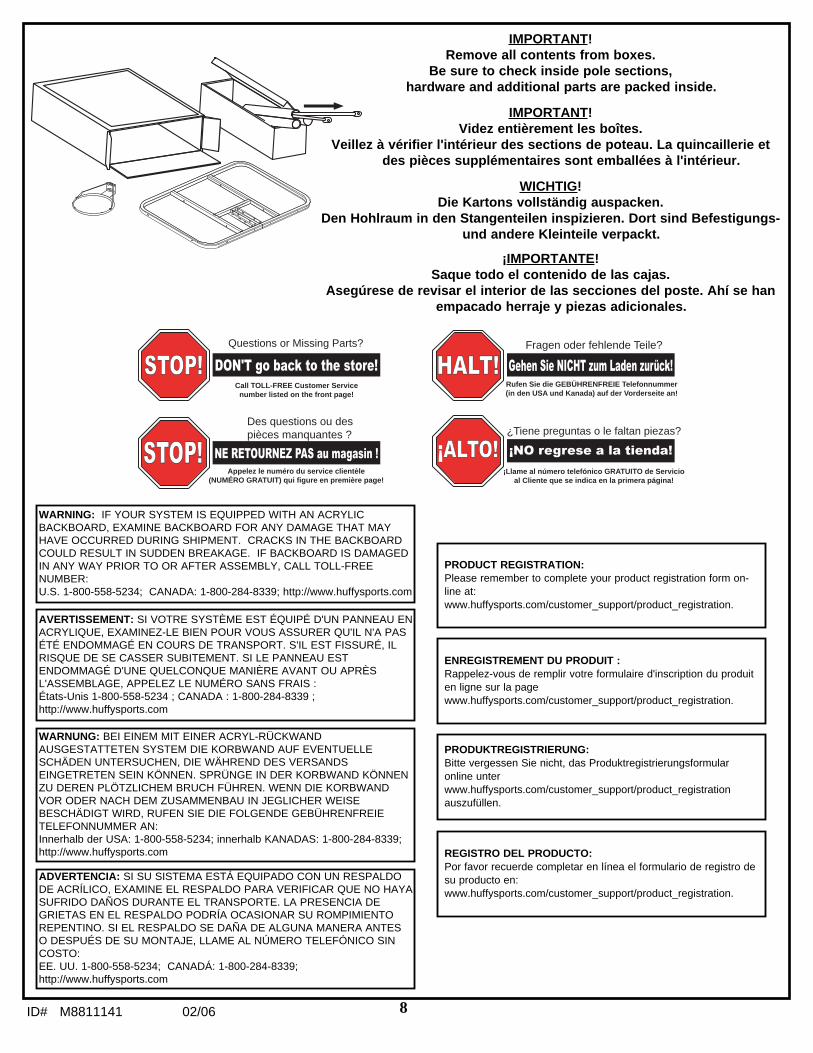
IMPORTANT!Remove all contents from boxes.
Be sure to check inside pole sections,hardware and additional parts are packed inside.
IMPORTANT!Videz entièrement les boîtes.
Veillez à vérifier l'intérieur des sections de poteau. La quincaillerie etdes pièces supplémentaires sont emballées à l'intérieur.
WICHTIG!Die Kartons vollständig auspacken.
Den Hohlraum in den Stangenteilen inspizieren. Dort sind Befestigungs-und andere Kleinteile verpackt.
¡IMPORTANTE!Saque todo el contenido de las cajas.
Asegúrese de revisar el interior de las secciones del poste. Ahí se hanempacado herraje y piezas adicionales.
Questions or Missing Parts?
Call TOLL-FREE Customer Servicenumber listed on the front page!
STOP!STOP! DON'T go back to the store!
STOP!
Des questions ou des pièces manquantes ?
Appelez le numéro du service clientèle (NUMÉRO GRATUIT) qui figure en première page!
STOP!STOP!
STOP!
NE RETOURNEZ PAS au magasin !
Fragen oder fehlende Teile?
Rufen Sie die GEBÜHRENFREIE Telefonnummer (in den USA und Kanada) auf der Vorderseite an!
HALT!HALT! Gehen Sie NICHT zum Laden zurück!
HALT!
¿Tiene preguntas o le faltan piezas?
¡Llame al número telefónico GRATUITO de Servicio al Cliente que se indica en la primera página!
¡ALTO!ALTO! ¡NO regrese a la tienda!
¡ALTO!
WARNING: IF YOUR SYSTEM IS EQUIPPED WITH AN ACRYLICBACKBOARD, EXAMINE BACKBOARD FOR ANY DAMAGE THAT MAYHAVE OCCURRED DURING SHIPMENT. CRACKS IN THE BACKBOARDCOULD RESULT IN SUDDEN BREAKAGE. IF BACKBOARD IS DAMAGEDIN ANY WAY PRIOR TO OR AFTER ASSEMBLY, CALL TOLL-FREENUMBER: U.S. 1-800-558-5234; CANADA: 1-800-284-8339; http://www.huffysports.com
AVERTISSEMENT: SI VOTRE SYSTÈME EST ÉQUIPÉ D'UN PANNEAU ENACRYLIQUE, EXAMINEZ-LE BIEN POUR VOUS ASSURER QU'IL N'A PASÉTÉ ENDOMMAGÉ EN COURS DE TRANSPORT. S'IL EST FISSURÉ, ILRISQUE DE SE CASSER SUBITEMENT. SI LE PANNEAU ESTENDOMMAGÉ D'UNE QUELCONQUE MANIÈRE AVANT OU APRÈSL'ASSEMBLAGE, APPELEZ LE NUMÉRO SANS FRAIS :États-Unis 1-800-558-5234 ; CANADA : 1-800-284-8339 ;http://www.huffysports.com
WARNUNG: BEI EINEM MIT EINER ACRYL-RÜCKWANDAUSGESTATTETEN SYSTEM DIE KORBWAND AUF EVENTUELLESCHÄDEN UNTERSUCHEN, DIE WÄHREND DES VERSANDSEINGETRETEN SEIN KÖNNEN. SPRÜNGE IN DER KORBWAND KÖNNENZU DEREN PLÖTZLICHEM BRUCH FÜHREN. WENN DIE KORBWANDVOR ODER NACH DEM ZUSAMMENBAU IN JEGLICHER WEISEBESCHÄDIGT WIRD, RUFEN SIE DIE FOLGENDE GEBÜHRENFREIETELEFONNUMMER AN:Innerhalb der USA: 1-800-558-5234; innerhalb KANADAS: 1-800-284-8339;http://www.huffysports.com
ADVERTENCIA: SI SU SISTEMA ESTÁ EQUIPADO CON UN RESPALDODE ACRÍLICO, EXAMINE EL RESPALDO PARA VERIFICAR QUE NO HAYASUFRIDO DAÑOS DURANTE EL TRANSPORTE. LA PRESENCIA DEGRIETAS EN EL RESPALDO PODRÍA OCASIONAR SU ROMPIMIENTOREPENTINO. SI EL RESPALDO SE DAÑA DE ALGUNA MANERA ANTESO DESPUÉS DE SU MONTAJE, LLAME AL NÚMERO TELEFÓNICO SINCOSTO:EE. UU. 1-800-558-5234; CANADÁ: 1-800-284-8339;http://www.huffysports.com
ENREGISTREMENT DU PRODUIT :Rappelez-vous de remplir votre formulaire d'inscription du produiten ligne sur la pagewww.huffysports.com/customer_support/product_registration.
PRODUCT REGISTRATION:Please remember to complete your product registration form on-line at:www.huffysports.com/customer_support/product_registration.
PRODUKTREGISTRIERUNG: Bitte vergessen Sie nicht, das Produktregistrierungsformularonline unterwww.huffysports.com/customer_support/product_registrationauszufüllen.
REGISTRO DEL PRODUCTO:Por favor recuerde completar en línea el formulario de registro desu producto en:www.huffysports.com/customer_support/product_registration.

02/06 ID# M88111419
2
2
1
3
201251 2/99
HEIGHT ADJUSTMENT
TO ADJUST BACKBOARD:
1. While holding handle, remove pin.
2. Move elevator up or down todesired height.
3. Replace pin full length to lock system at desired height.
35
2
2
1
3
201251 2/99
RÉGLAGE DE LA HAUTEUR
POUR AJUSTER LE PANNEAU :
1. Tout en tenant la poignée, retirez la goupille.
2. Montez ou abaissez le système élévateur jusqu'à la hauteur voulue.
3. Remettez la goupille à sa place en l'enfonçant à fond, pour bloquer le système à la hauteur désirée.
2
2
1
3
201251 2/99
HÖHENEINSTELLUNG
EINSTELLEN DER KORBWAND:
1. Bei festgehaltenem Griff den Stift herausziehen.
2. Die Verlängerungsvorrichtung bis zur gewünschten Höhe nach oben oder unten verschieben.
3. Den Stift zum Verriegeln des Systems auf der gewünschten Höhe ganz hineinschieben.
2
2
1
3
201251 2/99
PARA AJUSTAR EL RESPALDO:
1. Mientras sujeta la manija, quite el pasador.
2. Mueva el elevador hacia arriba o hacia abajo a la altura deseada.
3. Vuelva a colocar el pasador a toda su longitud para fijar el sistema a la altura deseada.
AJUSTE DE LA ALTURA
10ID# M8811141 02/06
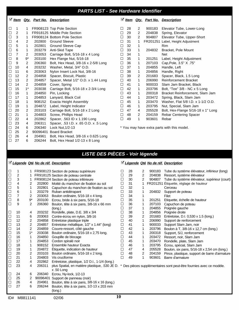
Item Qty. Part No. Description
1 1 FR908123 Top Pole Section2 1 FR918125 Middle Pole Section3 1 FR908124 Bottom Pole Section4 2 202800 Ground Sleeve5 1 202801 Ground Sleeve Cap6 1 203279 Anti-Skid Tape7 2 203053 Carriage Bolt, 5/16-18 x 4 Long8 9* 203100 Hex Flange Nut, 5/16-189 2 206360 Bolt, Hex Head, 3/8-16 x 2-5/8 Long
10 4 203232 Washer, Metal, 3/4” O.D.11 6 203063 Nylon Insert Lock Nut, 3/8-1612 2 204858 Spacer, Biscuit, Plastic13 2 204857 Spacer, Metal 1/2” O.D. x 1.44 Long14 2 204859 Cover, Spring15 1* 203038 Carriage Bolt, 5/16-18 x 2-3/4 Long16 1 204850 Pin, Locking17 1 204853 Lanyard, Black Coil18 1 908152 Exacta Height Assembly19 1 204872 Label, Height Indicator20 2 203103 Carriage Bolt, 5/16-18 x 2 Long21 1 204803 Screw, Phillips Head22 4 202862 Spacer, .563 ID x 1.190 Long23 4 206311 Spacer, .53 I.D. x .65 O.D. x .5 Long 24 6 206340 Lock Nut,1/2-1325 2 90096401 Board Bracket26 4 204961 Bolt, Hex Head, 3/8-16 x 0.625 Long27 6 206244 Bolt, Hex Head 1/2-13 x 8 Long
Item Qty. Part No. Description
28 2 900183 Elevator Tube, Lower-Long29 2 204838 Spring, Elevator30 2 904807 Elevator Tube, Upper-Short31 1 FR201251 Label, Height Adjustment32 1 Rim33 1 204832 Bracket, Pole Mount34 1 Net35 1 201251 Label, Height Adjustment36 1 207103 Cap,Pole, 3.5" X .75"37 1 204855 Handle, Left38 1 204856 Handle, Right39 2 201683 Spacer, Black, 1.5 Long40 1 206990 Reinforcement Bracket41 1 900033 Slam Jam Bracket, Black42 1 203796 Bolt, “Tee” 3/8 - NC x 5 Long43 1 200318 Bracket Reinforcement, Slam Jam44 1 203472 Spring, Black, Slam Jam45 1 203470 Washer, Flat 5/8 I.D. x 1-1/2 O.D.46 1 203795 Nut, Special, Slam Jam47 4 205528 Bolt, Hex-Flange 5/16-18 x 1" Long48 2 204159 Rebar Centering Spacer49 1 903601 Rebar
* You may have extra parts with this model.
PARTS LIST - See Hardware Identifier
LISTE DES PIÈCES - Voir légende
Légende Qté No de réf. Description
1 1 FR908123 Section de poteau supérieure2 1 FR918125 Section de poteau centrale3 1 FR908124 Section de poteau inférieure4 2 202800 Moitié du manchon de fixation au sol5 1 202801 Capuchon du manchon de fixation au sol6 1 203279 Ruban antidérapant7 2 203053 Boulon ordinaire, 5/16-18 x 4 long.8 9* 203100 Ecrou, bride à six pans, 5/16-189 2 206360 Boulon, tête à six pans, 3/8-16 x 66 mm
(long.)10 4 203232 Rondelle, plate, D.E. 3/8 x 3/411 6 203063 Contre-écrou en nylon, 3/8-1612 2 204858 Entretoise plastique triple13 2 204857 Entretoise métallique, 1/2" x 1.44" (long)14 2 204859 Couvre-ressort, côté gauche15 1* 203038 Boulon ordinaire, 5/16-18 x 2,75 long.16 1 204850 Goupille de blocage17 1 204853 Cordon spiralé noir18 1 908152 Ensemble hauteur Exacta19 1 204872 Étiquette, indication de hauteur20 2 203103 Boulon ordinaire, 5/16-18 x 2 long.21 1 204803 Vis cruciforme22 4 202862 Entretoise, plastique, 1/2 D.I., 1-1/4 (long.)23 4 206311 plus Spatial, en matière plastique, .530 JE D.
x .50 Long 24 6 206340 Ecrou, Ny-lock, 1/2-1325 2 90096401 Support de panneau (noir)26 4 204961 Boulon, tête à six pans, 3/8-16 x 16 (long.)27 6 206244 Boulon, tête à six pans, 1/2-13 x 203 mm
(long.)
Légende Qté No de réf. Description
28 2 900183 Tube du système élévateur, inférieur (long)29 2 204838 Ressort, système élévateur30 2 904807 Tube du système élévateur, supérieur (court)31 1 FR201251 Étiquette, réglage de hauteur32 1 Cerceau33 1 204832 Support de poteau34 1 Filet35 1 201251 Etiquette, échelle de hauteur36 1 207103 Capuchon de poteau37 1 204855 Poignée gauche38 1 204856 Poignée droite39 2 201683 Entretoise, D.I. 0,530 x 1.5 (long.)40 1 206990 Support de renforcement41 1 900033 Support Slam Jam, noir42 1 203796 Boulon à T, 3/8-16 x 12,7 cm (long.)43 1 200318 Support, S/J, renforcement44 1 203472 Ressort, noir, Slam Jam45 1 203470 Rondelle, plate, Slam Jam46 1 203795 Écrou, spécial, Slam Jam47 4 205528 Boulon, six pans, 5/16-18 x 2,54 cm (long.)48 2 204159 Pince, plastique, support de barre d'armature49 1 903601 Barre d'armature
* Des pièces supplémentaires sont peut-être fournies avec ce modèle.

02/06 ID# M881114111
TEILELISTE - Siehe Teileschlüssel
LISTA DE PIEZAS - Vea el identificador de herraje
Artículo Cant. Pieza N.º Descripción
1 1 FR908123Sección superior del poste2 1 FR918125Sección media del poste3 1 FR908124Sección inferior del poste4 2 202800 Mitad de la manga del piso5 1 202801 Tapa de la manga del piso6 1 203279 Cinta antiderrapante7 2 203053 Perno cabeza de carro, 5/16-18 x 4 de
longitud8 9* 203100 Tuerca, brida hexagonal, 5/16-189 2 206360 Perno, hexagonal, 3/8-16 x 2.625" de
longitud10 4 203232 Arandela de metal, ¾" D.E.11 6 203063 Tuerca de nilón del inserto de seguridad,
3/8-1612 2 204858 Espaciador, oblongo, plástico 13 2 204857 Espaciador, de metal, ½" de D.E. x 1,44 de
largo14 2 204859 Cubierta, corredera de perno15 1* 203038 Perno cabeza de carro, 5/16-18 x 2 -3/4 de
longitud16 1 204850 Perno de fijación17 1 204853 Acollador, espiral negro18 1 908152 Conjunto Exacta Height19 1 204872 Etiqueta, indicadora de altura20 2 203103 Perno cabeza de carro, 5/16-18 x 2 de
longitud21 1 204803 Tornillo, cabeza en cruz22 4 202862 Espaciador de plástico, 1.19" de longitud23 4 206311 Espaciador, el Plástico, .530 yo. D. X .50
Largo 24 6 206340 Contratuerca, cabeza hexagonal, 1/2-1325 2 90096401 Soporte del respaldo26 4 204961 Perno, cabeza hexagonal, 3/8-16 x 0.625 de
longitud
Artículo Cant. Pieza N.º Descripción
27 6 206244 Perno, cabeza hexagonal, 1/2-13 x 8 delongitud
28 2 900183 Tubo elevador, inferior-largo29 2 204838 Resorte, elevador30 2 904807 Tubo elevador, superior-corto31 1 FR201251 Etiqueta, ajuste de la altura32 1 Borde33 1 204832 Soporte, montaje del poste34 1 Red35 1 201251 Etiqueta, ajuste de la altura36 1 207103 Tapa, parte superior del poste37 1 204855 Manija, izquierda38 1 204856 Manija, derecha39 2 201683 Espaciador 0.530 D.I. x 1.5 de longitud40 1 206990 Soporte de refuerzo41 1 900033 Soporte, negro, Slam Jam42 1 203796 Perno T, 3/8-16 x 5” de longitud43 1 200318 Soporte de refuerzo, Slam Jam44 1 203472 Resorte, negro, Slam Jam45 1 203470 Arandela plana, Slam Jam46 1 203795 Tuerca, especial, Slam Jam47 4 205528 Perno, brida hexagonal, 5/16-18 x 1 de
longitud48 2 204159 Sujetador, plástico, sujetador de la barra de
refuerzo49 1 903601 Barra de refuerzo
* Puede haber piezas adicionales en este modelo.
Nr. Anz. Teilenummer Beschreibung
1 1 FR908123 Oberes Stangenteil2 1 FR918125 Mittleres Stangenteil3 1 FR908124 Unteres Stangenteil4 2 202800 Bodenmuffenhälfte5 1 202801 Bodenmuffenabdeckung6 1 203279 Rutschfestes Band7 2 203053 Schlossschraube, 5/16-18 x 4 Länge8 9* 203100 Sechskant-Flanschmutter, 5/16-189 2 206360 Sechskantkopfschraube, 3/8-16 x 2.625 Zoll
Länge10 4 203232 Unterlegscheibe, Metall, 3/4 Zoll AD11 6 203063 Nylon-Einschraubgegenmutter, 3/8-1612 2 204858 Abstandsstück, rund, Plastik13 2 204857 Abstandsstück, Metall, 1/2 Zoll AD x 1,44
Zoll Länge14 2 204859 Stiftschiebeabdeckung15 1* 203038 Schlossschraube, 5/16-18 x 2-3/4 Länge16 1 204850 Verriegelungsstift17 1 204853 Abzugsleine, schwarze Rolle18 1 908152 Exacta-Höheneinstellkomponenten19 1 204872 Höhenanzeigeaufkleber20 2 203103 Schlossschraube, 5/16-18 x 2 Länge21 1 204803 Kreuzschlitz-Kopfschraube22 4 202862 Abstandsstück, Plastik, 1,19 Zoll Länge23 4 206311 Abstandsstück, Kunststoff, .530 ICH D. x
.50 Lange 24 6 206340 Sechskant-Gegenmutter, 1/2-1325 2 90096401 Korbwandstützklammer26 4 204961 Sechskantkopfschraube, 3/8-16 x 0.625
Länge
Nr. Anz. Teilenummer Beschreibung
27 6 206244 Sechskantkopfschraube, 1/2-13 x 8 Länge28 2 900183 Unteres langes Verlängerungsrohr29 2 204838 Verlängerungsfeder30 2 904807 Oberes kurzes Verlängerungsrohr31 1 FR201251 Höheneinstell32 1 Korbrand33 1 204832 Stangenmontageklammer34 1 Netz35 1 201251 Höheneinstellkleber36 1 207103 Stangenendkappe37 1 204855 Griff, links38 1 204856 Griff, rechts39 2 201683 Abstandsstück, 0,530 ID x 1,5 Länge40 1 206990 Verstärkungshalterung41 1 900033 Slam Jam-Halterung, schwarz42 1 203796 T-Nutenschraube, 3/8-16 x 5 Zoll Länge43 1 200318 Slam Jam-Verstärkungshalterung44 1 203472 Slam Jam-Feder, schwarz45 1 203470 Flache Slam Jam-Unterlegscheibe46 1 203795 Slam Jam-Spezialmutter47 4 205528 Sechskant-Flanschschraube, 5/16-18 x 1
Länge48 2 204159 Versteifungsstangen-Halteclip, Plastik49 1 903601 Versteifungsstange
* Diesem Modell können zusätzliche Teile beigepackt sein.

12ID# M8811141 02/06
#8 (9)*
#10 (4)
#13 (2)
#7 (2)
#11 (6)
#15 (1)*
#20 (2)
#24 (6)
#21 (1)
#27 (6)
#42 (1)
#46 (1) #45 (1)
#47 (4)
#9 (4)
HARDWARE IDENTIFIER (NUTS & WASHERS)IDENTIFICATION DES PIÈCES (ÉCROUS & RONDELLES)
BEFESTIGUNGSTEILESCHLÜSSEL (MUTTERN UND UNTERLEGSCHEIBEN)IDENTIFICADOR DE HERRAJE (TUERCAS Y ARANDELAS)
HARDWARE IDENTIFIER (BOLTS & SCREWS)IDENTIFICATION DES PIÈCES (BOULONS & VIS)
BEFESTIGUNGSTEILESCHLÜSSEL (BOLZEN UND SCHRAUBEN)IDENTIFICADOR DE HERRAJE (PERNOS Y TORNILLOS)
HARDWARE IDENTIFIER (STEEL SPACERS & RODS)IDENTIFICATION DES PIÈCES (ENTRETOISES EN ACIER)
BEFESTIGUNGSTEILESCHLÜSSEL (ABSTANDSSTÜCKE AUS STAHL)IDENTIFICADOR DEL HERRAJE (ESPACIADORES DE ACERO)
#26 (4)

02/06 ID# M881114113
#44 (1)
#41 (1)
#43 (1)
#23 (4)#22 (4)
#12 (2)
#39 (2)
HARDWARE IDENTIFIER (PLASTIC SPACERS & CLIPS)IDENTIFICATION DES PIÈCES (ENTRETOISES, CAPUCHONS & PINCES EN PLASTIQUE)
BEFESTIGUNGSTEILESCHLÜSSEL (ABSTANDSSTÜCKE, KAPPEN UND CLIPS AUS KUNSTSTOFF)IDENTIFICADORES DEL HERRAJE (TAPAS DE LOS ESPACIADORES Y SUJETADORES DE PLÁSTICO)
HARDWARE IDENTIFIER (OTHER) IDENTIFICATION DES PIÈCES (AUTRES)
BEFESTIGUNGSTEILESCHLÜSSEL (SONSTIGE)IDENTIFICADOR DE HERRAJE (OTROS)

14ID# M8811141 02/06
SECTION A: ASSEMBLE THE POLESSECTION A: ASSEMBLAGE DES SECTIONS DE POTEAU
BAUABSCHNITT A: ZUSAMMENBAU DER STANGENTEILESECCIÓN A: MONTAJE DE LAS SECCIONES DEL POSTE
This is what your system will look like when you’vefinished this section.
Voici à quoi ressemblera votre système lorsque vous enaurez fini avec cette section.
So sieht das System aus, wenn Sie mit diesemBauabschnitt fertig sind.
Así es como se verá su sistema cuando haya terminadoesta sección.
ITEMS REQUIRED FOR THIS SECTIONOUTILS REQUIS POUR CETTE SECTION
FÜR DIESEN BAUABSCHNITT BENÖTIGTE GEGENSTÄNDEARTÍCULOS REQUERIDOS PARA ESTA SECCIÓN
Phillips-Head ScrewdriverTournevis cruciforme
KreuzschlitzschraubenzieherDestornillador Phillips
Container to MixRécipient pour mélanger
Behälter zum MischenRecipiente para mezclar
CONCRETEBÉTONBÉTON
CONCRETO
9/16”1/2”
(2) 1/2” and (2) 9/16" Wrenches(2) clés 1/2" et (2) clés 9/16"
(2) 1/2 und (2) 9/16-Zoll-Schraubenschlüssel(2) Llaves de 1/2", y (2) de 9/16"
(2) Socket Wrenches and Sockets(2) clés à douille et douilles
(2) Steckschlüssel und Einsätze(2) Llaves de tuercas de boca tubular y casquillos de
AND/ORET/OU
UND/ODERY/O
Shovel and Post Hole DiggerPelle et bêchet arière
Schaufel und ErdlochbohrerPala y excavador del orificio para el poste
Carpenter’s LevelNiveau à bulleWasserwaage
Nivel de carpintero

02/06 ID# M881114115
1. Correctly identify each pole section.
Identifiez correctement chaque sectionde poteau.
Jedes Stangenteil richtig identifizieren.
Identifique correctamente cada seccióndel poste.
18" (42.7 cm)6" (15.2 cm)
24" (61 cm)
PLAYING SURFACESURFACE DE JEU
SPIELFLÄCHESUPERFICIE DE JUEGO
GROUND SURFACESURFACE DU SOL
BODENFLÄCHESUPERFICIE DEL PISO
2. Ensure ground is level with playing surface, then dig pole hole.
Assurez-vous que le sol est au niveau de la surface de jeu, puiscreusez le trou pour le poteau.
Sicherstellen, dass der Boden auf gleicher Höhe mit der Spielfläche istund ein Loch für die Stange graben.
Asegúrese de que el piso esté nivelado con la superficie de juego yluego haga el orificio para el poste.
IMPORTANT!IMPORTANT!
WICHTIG!¡IMPORTANTE!
Maximum distance from edge of hole to edgeof playing surface 6” (15.2 cm).
La distance maximale du bord du trou aubord de la surface de jeu est de 15,2 cm.
Der maximale Abstand vom Lochrand zumRand der Spielfläche beträgt 15,2 cm (6").
La distancia máxima desde el borde delorificio hasta el borde de la superficie dejuego es de 6" (15,2 cm).
CONTACT UTILITIES BEFORE DIGGING.
CONTACTEZ LES RÉSEAUX LOCAUX (GAZ,ÉLECTRICITÉ...) AVANT DE CREUSER.
VOR DEM GRABEN ENTSPRECHENDEINFORMATIONEN VON DEN ZUSTÄNDIGENVERSORGUNGSWERKEN EINHOLEN.
COMUNÍQUESE CON LAS COMPAÑÍAS DESERVICIO ANTES DE EXCAVAR.
WARNING!AVERTISSEMENT!
ACHTUNG!¡ADVERTENCIA!
TOP / SUPÉRIEURE /OBEN / SUPERIOR
Pole Identification StickerÉtiquette d'identification de section de poteau
StangenmarkierungCalcomanía de identificación de la sección del poste BOTTOM / INFÉRIEURE /
UNTEN / SECCIÓN INFERIOR
MIDDLE / CENTRALE /MITTE / MEDIA
Pole Identification StickerÉtiquette d'identification de section de poteau
StangenmarkierungCalcomanía de identificación de la sección del poste
1
2
3

16ID# M8811141 02/06
4.
3.
3
5
4
4
Snap two halves of ground sleeve (4) together. Insert and secure bottom pole section (3) into ground sleeve (4)by tightening ground sleeve cap (5).
Enclenchez les deux moitiés du manchon de fixation au sol (4) l'une dans l'autre. Insérez et fixez la section depoteau inférieure (3) dans le manchon de fixation au sol (4) en serrant le capuchon du manchon de fixation ausol (5).
Die beiden Hälften der Bodenmuffe (4) zusammendrücken, bis sie ineinander einrasten. Das untere Stangenteil (3) in die Bodenmuffe (4) stecken und durch Festdrehen der Bodenmuffenabdeckung (5) gutsichern.
Conecte las dos mitades de la manga del piso (4). Introduzca y fije la sección inferior delposte (3) en la manga del piso (4) apretando la tapa de la manga del piso (5).
Flared end goes inside groundsleeve.
L'extrémité évasée rentre dans lemanchon de fixation au sol.
Das konisch erweiterte Ende wird indie Bodenmuffe gesteckt.
El extremo abocinado debe quedardentro de la manga del piso.
NOTE:REMARQUE:
HINWEIS:NOTA:
Fill hole approximately 1/3 full with mixed concrete.
Remplissez le trou de béton, au tiers environ.
Das Loch zu etwa 1/3 mit gemischtem Beton füllen.
Llene aproximadamente una tercera parte del orificio con concretomezclado.
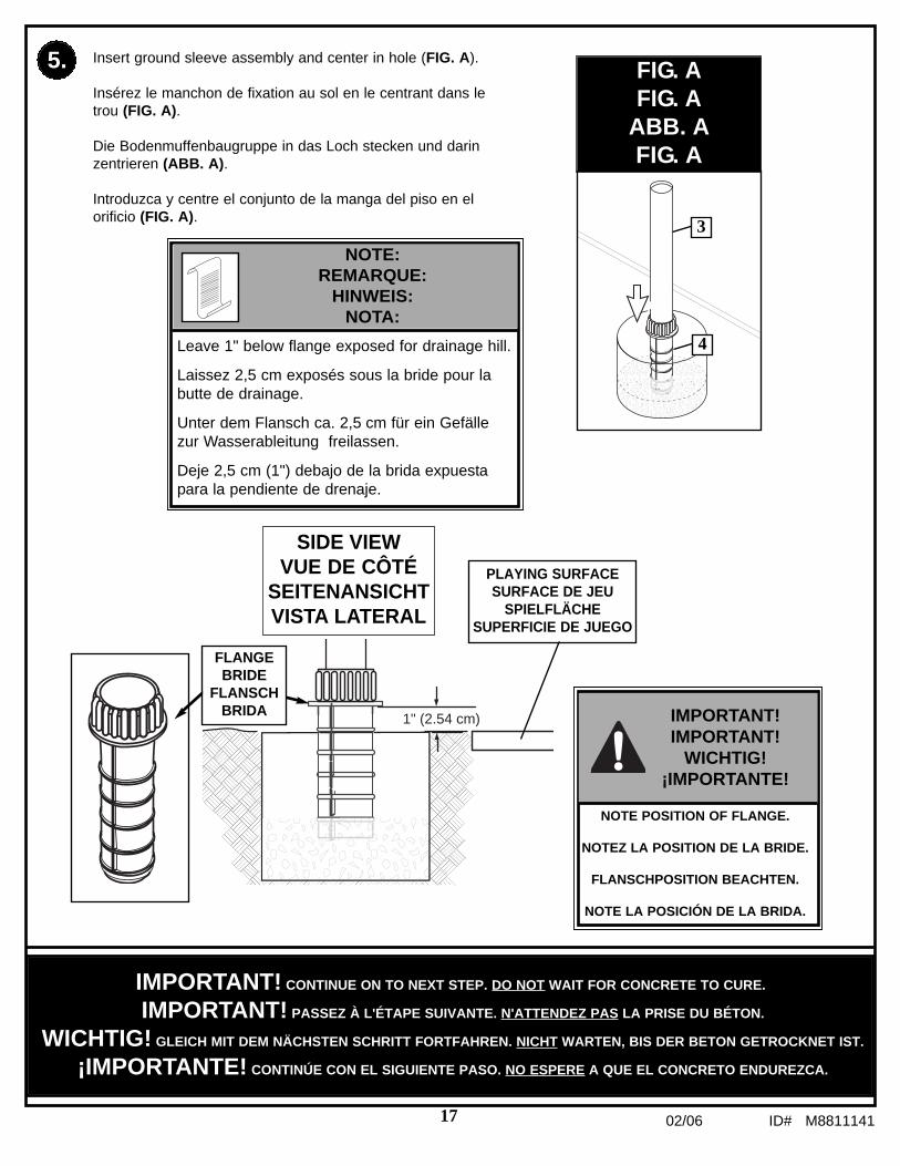
02/06 ID# M881114117
FIG. AFIG. A
ABB. AFIG. A
5. Insert ground sleeve assembly and center in hole (FIG. A).
Insérez le manchon de fixation au sol en le centrant dans letrou (FIG. A).
Die Bodenmuffenbaugruppe in das Loch stecken und darinzentrieren (ABB. A).
Introduzca y centre el conjunto de la manga del piso en elorificio (FIG. A).
Leave 1" below flange exposed for drainage hill.
Laissez 2,5 cm exposés sous la bride pour labutte de drainage.
Unter dem Flansch ca. 2,5 cm für ein Gefällezur Wasserableitung freilassen.
Deje 2,5 cm (1") debajo de la brida expuestapara la pendiente de drenaje.
NOTE:REMARQUE:
HINWEIS:NOTA:
IMPORTANT! CONTINUE ON TO NEXT STEP. DO NOT WAIT FOR CONCRETE TO CURE.
IMPORTANT! PASSEZ À L'ÉTAPE SUIVANTE. N'ATTENDEZ PAS LA PRISE DU BÉTON.
WICHTIG! GLEICH MIT DEM NÄCHSTEN SCHRITT FORTFAHREN. NICHT WARTEN, BIS DER BETON GETROCKNET IST.
¡IMPORTANTE! CONTINÚE CON EL SIGUIENTE PASO. NO ESPERE A QUE EL CONCRETO ENDUREZCA.
1" (2.54 cm)
SIDE VIEWVUE DE CÔTÉ
SEITENANSICHTVISTA LATERAL
FLANGEBRIDE
FLANSCHBRIDA
PLAYING SURFACESURFACE DE JEU
SPIELFLÄCHESUPERFICIE DE JUEGO
IMPORTANT!IMPORTANT!
WICHTIG!¡IMPORTANTE!
NOTE POSITION OF FLANGE.
NOTEZ LA POSITION DE LA BRIDE.
FLANSCHPOSITION BEACHTEN.
NOTE LA POSICIÓN DE LA BRIDA.
4
3

18ID# M8811141 02/06
3Fill hole completely with concrete.
Remplissez complètement le trou de béton.
Das Loch vollständig mit Beton füllen.
Llene el orificio completamente conconcreto.
6.
1" (2.54 cm)
5
1" (2.54 cm)
7. Tamp down concrete to release air pockets and build drainage hill. Level pole section in all directions several timeswhile concrete is curing.
Tassez le béton pour éliminer les poches d'air et formez une butte de drainage. Mettez le poteau à niveau plusieurs foisdans toutes les directions pendant le séchage du béton.
Den Beton feststampfen, um Lufteinschlüsse zu beseitigen, und ein Gefälle zur Wasserableitung bilden. DasStangenteil während des Trocknens des Betons mehrmals in alle Richtungen begradigen.
Apisone el concreto para eliminar las bolsas de aire y construya una pendiente para el drenaje. Nivele varias veces lasección del poste en todas direcciones mientras el concreto se está endureciendo.
1" (2.54 cm)
SIDE VIEWVUE DE CÔTÉ
SEITENANSICHTVISTA LATERAL
DRAINAGE HILL
INCLINAISON DEDRAINAGE
GEFÄLLE ZURWASSERABLEITUN
PENDIENTE DEDRENAJE
IMPORTANT! CONTINUE ON TO NEXT STEP. DO NOT WAIT FOR CONCRETE TO CURE.
IMPORTANT! PASSEZ À L'ÉTAPE SUIVANTE. N'ATTENDEZ PAS LA PRISE DU BÉTON.
WICHTIG! GLEICH MIT DEM NÄCHSTEN SCHRITT FORTFAHREN. NICHT WARTEN, BIS DER BETON GETROCKNET IST.
¡IMPORTANTE! CONTINÚE CON EL SIGUIENTE PASO. NO ESPERE A QUE EL CONCRETO ENDUREZCA.
PLAYING SURFACESURFACE DE JEU
SPIELFLÄCHESUPERFICIE DE JUEGO
Make a reference mark here foranti-skid tape.
Marquez ce point en prévision del'application de ruban adhésif.
Hier eine Bezugsmarkierung fürdas Fixierband anbringen.
Haga una marca de referenciaaquí para la cinta antiderrapante.
NOTE A:REMARQUE A:HINWEIS A:
NOTA A:
Keep flange pushed down toconcrete and leveled.
Maintenez la bride enfoncéejusqu'au béton et à niveau.
Den Flansch am Betonangedrückt lassen und nivellieren.
Mantenga la brida presionadahacia el concreto y nivelada.
NOTE B:REMARQUE B:
HINWEIS B:NOTA B:
4

02/06 ID# M881114119
After concrete has cured, remove bottom pole section from ground sleeve (4). Place anti-skid tape (6) around thebottom area of bottom pole (see note A).
Une fois le béton sec, retirez la section de poteau inférieure du manchon de fixation au sol (4). Placez du rubanantidérapant (6) autour de la base du poteau (cf. remarque A).
Nachdem der Beton getrocknet ist, das untere Stangenteil aus der Bodenmuffe (4) herausziehen. Fixierband (6) umdas untere Ende der unteren Stange wickeln (siehe Hinweis A).
Cuando se endurezca el concreto, separe la sección inferior del poste de la manga del piso (4). Coloque la cintaantiderrapante (6) alrededor del área inferior de la sección inferior del poste (vea la nota A).
4
8.
5
IMPORTANT! WAIT A MINIMUM OF 24 HOURS BEFORE GOING ON TO NEXT STEP. CONCRETE MUST CURE.
IMPORTANT! ATTENDEZ AU MOINS 24 HEURES AVANT DE PASSER À L'ÉTAPE SUIVANTE. LE BÉTON DOIT FINIR
DE PRENDRE.
WICHTIG! VOR DEM NÄCHSTEN ARBEITSSCHRITT MINDESTENS 24 STUNDEN LANG WARTEN. DER BETON MUSS
TROCKNEN.
¡IMPORTANTE! ESPERE UN MÍNIMO DE 24 HORAS ANTES DE CONTINUAR CON EL PASO SIGUIENTE. EL
CONCRETO DEBE ENDURECERSE.
Surface de jeu
Spielfläche
Superficie de juego
Keep ground sleeve cap on bottom pole.
Maintenez le capuchon du manchon de fixationau sol sur la section de poteau inférieure
Die Bodenmuffenabdeckung auf der unterenstange lassen.
Mantenga la tapa de la manga del piso en lasección inferior del poste.
IMPORTANT!IMPORTANT!
WICHTIG!¡IMPORTANTE!
6
Place top edge of anti-skid tape onmark made in step 7, NOTE A.
Placez le bord supérieur du rubanantidérapant sur le repère posé à
l'étape 7, REMARQUE A.
Die obere Kante des Fixierbands aufder in Schritt 7 angebrachten
Markierung ankleben (HINWEIS A).
Coloque el borde superior de la cintaantiderrapante en la marca que hizo
en el paso 7, NOTA A.
NOTE A:REMARQUE A:HINWEIS A:
NOTA A:
Tape prevents the pole from rotatingduring play.
Le ruban empêche la rotation dupoteau durant le jeu.
Das Fixierband verhindert, dass sichdie Stange während des
Spielbetriebs dreht.
La cinta evita que el poste giredurante el juego.
NOTE B:REMARQUE B:
HINWEIS B:NOTA B:

20ID# M8811141 02/06
Stack and bounce bottom (3) and middle (2) pole sections together. Bounce pole sections together until middle sectionno longer moves toward taped reference mark on bottom pole.
Empilez et entrechoquez les sections de poteau centrale (2) et inférieure (3). Entrechoquez-les jusqu'à ce que la sectioncentrale ne bouge plus vers la marque de référence (ruban) de la section inférieure.
Das untere (3) und mittlere (2) Stangenteil aufeinander stellen und zusammenstauchen. Die Stangenteilezusammenstauchen, bis sich die mittlere Stange nicht mehr auf die mit Klebeband markierte Stelle auf dem unterenStangenteil zu bewegt.
Apile y golpee entre sí las secciones inferior (3) y media (2) del poste. Golpee entre sí las secciones del poste hasta que lasección media ya no se mueva hacia la marca de referencia con cinta que se encuentra en la sección inferior del poste.
2
3
Wood Scrap (NOT SUPPLIED)Chute de bois (NON FOURNIE)
Holzstück (NICHT IM LIEFERUMFANGENTHALTEN)
Trozo de madera (NO SE SUMINISTRA)
Identification StickerÉtiquette d'identification
MarkierungsaufkleberCalcomanías de identificaciónIMPORTANT!
IMPORTANT!WICHTIG!
¡IMPORTANTE!
POLE SECTIONS SHOULD HAVE A3-1/2" (9 CM) MINIMUM OVERLAP.
LES SECTIONS DE POTEAUDOIVENT SE CHEVAUCHER DE 9 CMMINIMUM.
DIE STANGENTEILE MÜSSENEINANDER UM MINDESTENS 9 CM (3 ½ ZOLL) ÜBERLAPPEN.
LAS SECCIONES DEL POSTE SEDEBEN TRASLAPAR UN MÍNIMO DE3-1/2" (9 CM).
KEEP GROUND SLEEVE CAP ONBOTTOM POLE.
MAINTENEZ LE CAPUCHON DUMANCHON DE FIXATION AU SOLSUR LA SECTION DE POTEAUINFÉRIEURE
DIE BODENMUFFENABDECKUNGAUF DER UNTEREN STANGELASSEN.
MANTENGA LA TAPA DE LA MANGADEL PISO EN LA SECCIÓNINFERIOR DEL POSTE.
1-1/2"(3.81 cm)5"
(12.7 cm)
5
9.
THE IDENTIFICATION STICKER IS LOCATED 5" FROM THE END OF THE POLE. WHEN PROPERLY POUNDED TOGETHER, THE POLE SECTIONS SHOULDHAVE A 3-1/2" MINIMUM OVERLAP, LEAVING 1-1/2" BETWEEN THE OVERLAPPING POLE AND THE IDENTIFICATION STICKER.
L'ÉTIQUETTE D'IDENTIFICATION SE SITUE À 12,7 CM DE L'EXTRÉMITÉ DU POTEAU. LORSQU'ELLES SONT CORRECTEMENT EMBOÎTÉES LES UNES DANSLES AUTRES, LES SECTIONS DE POTEAU DOIVENT SE CHEVAUCHER DE 9 CM MINIMUM, EN LAISSANT 3,8 CM ENTRE LA SECTION QUI CHEVAUCHE ETL'ÉTIQUETTE D'IDENTIFICATION.
DER MARKIERUNGSAUFKLEBER IST IN EINER ENTFERNUNG VON CA. 12,7 CM VOM STANGENENDE ANGEBRACHT. WENN DIE STANGENTEILE RICHTIGZUSAMMENGESTAUCHT WURDEN, SOLLTEN SIE EINANDER UM MINDESTENS 9 CM ÜBERLAPPEN. DER ABSTAND ZWISCHEN DEM ÜBERLAPPENDENSTANGENTEIL UND DEM MARKIERUNGSAUFKLEBER SOLLTE ALSO 3,8 CM BETRAGEN.
LA CALCOMANÍA DE IDENTIFICACIÓN ESTÁ COLOCADA A 12.7 CM (5") DEL EXTREMO DEL POSTE. CUANDO ESTÁN ADECUADAMENTE EMBRAGADAS,LAS SECCIONES DEL POSTE DEBEN TENER UN TRASLAPE MÍNIMO DE 8.9 CM (3 1/2"), DEJANDO 3.8 CM (1 1/2") ENTRE EL POSTE TRASLAPADO Y LACALCOMANÍA DE IDENTIFICACIÓN.
CAUTION! / ATTENTION! / VORSICHT! / ¡PRECAUCIÓN!

02/06 ID# M881114121
10. Stack upper pole section (1) to bottom and middle pole assembly and continue bouncing until top pole (1) nolonger moves toward taped reference mark on middle pole.
Empilez la section de poteau supérieure (1) sur l'ensemble des sections de poteau inférieure et centrale, puiscontinuez à entrechoquer jusqu'à ce que la section supérieure (1) ne bouge plus vers la marque de référence(ruban) de la section centrale.
Das obere Stangenteil (1) auf den aus dem unteren und mittleren Stangenteil bestehenden Aufbau aufsetzen undweiter so lange zusammenstauchen, bis sich das obere Teil (1) nicht mehr auf die mit Klebeband markierte Stelleam mittleren Teil zu bewegt.
Apile la sección superior del poste (1) con el conjunto de las secciones inferior y media del poste y continúegolpeando hasta que la sección superior del poste (1) ya no se mueva hacia la marca de referencia con cinta dela sección media del poste.
1
5
IMPORTANT!IMPORTANT!
WICHTIG!¡IMPORTANTE!
POLE SECTIONS SHOULD HAVE A 3-1/2" (9 CM) MINIMUM OVERLAP.
LES SECTIONS DE POTEAUDOIVENT SE CHEVAUCHER DE 9 CMMINIMUM.
DIE STANGENTEILE MÜSSENEINANDER UM MINDESTENS 9 CM (3 ½ ZOLL) ÜBERLAPPEN.
LAS SECCIONES DEL POSTE SEDEBEN TRASLAPAR UN MÍNIMO DE3-1/2" (9 CM).
1-1/2"(3.81 cm)5"
(12.7 cm)
Wood Scrap (NOT SUPPLIED)Chute de bois (NON FOURNIE)
Holzstück (NICHT IM LIEFERUMFANG ENTHALTEN)Trozo de madera (NO SE SUMINISTRA)
Identification StickerÉtiquette d'identification
MarkierungsaufkleberCalcomanías de identificación
IMPORTANT!IMPORTANT!
WICHTIG!¡IMPORTANTE!
WARNING
FAILURE TO FOLLOW THESE WARNINGS MAY RESULT
IN SERIOUS INJURY AND/OR PROPERTY DAMAGE.
Owner must ensure that all players know and follow
these rules for safe operation of the system.
• DO NOT HANG on the rim or any part of the system
including backboard, support braces or net.
• During play, especially when performing dunk type
activities, keep player's face away from the backboard, rim
and net. Serious injury could occur if teeth/face come in
contact with backboard, rim or net.
• Do not slide, climb, shake or play on base and/or pole.
• After assembly is complete, fill system completely with
water or sand and stake to the ground. Never leave system
in an upright position without filling base with weight, as
system may tip over causing injuries.
• When adjusting height or moving system, keep hands and
fingers away from moving parts.
• Do not allow children to move or adjust system.
• During play, do not wear jewelry (rings, watches, necklaces,
etc.). Objects may entangle in net.
• Surface beneath the base must be smooth and free of
gravel or other sharp objects. Punctures cause leakage and
could cause system to tip over.
• Keep organic material away from pole base. Grass, litter,
etc. could cause corrosion and/or deterioration.
• Check pole system for signs of corrosion (rust, pitting,
chipping) and repaint with exterior enamel paint. If rust has
penetrated through the steel anywhere, replace pole
immediately.• Check system before each use for proper ballast, loose
hardware, excessive wear and signs corrosion and repair
before use.• Check system before each use for instability.
• Do not use system during windy and/or severe weather
conditions; system may tip over. Place system in the
storage position and/or in an area protected from the wind
and free from personal property and/or overhead wires.
• Never play on damaged equipment.
• See instruction manual for proper installation and
maintenance.• When moving system, use caution to keep mechanism from
shifting.• Keep pole top covered with cap at all times.
• Do not allow water in tank to freeze. During sub-freezing
weather add non-toxic antifreeze, sand or empty tank
completely and store. (Do not use salt.)
• Use extreme caution if placing system on sloped surface.
System may tip over more easily.
201241 2/99
In the U.S.:1-800-558-5234 and Canada: 1-800-284-8339
The warning label should be 90 degeesfrom uppermost holes on top pole (1) - seeIllustration.
L'étiquette d'avertissement doit se trouver à90 degrés des trous situés en haut de lasection de poteau supérieure (1) - voirl'illustration.
Der Warnaufkleber muss um 90 Grad vonden obersten Löchern im oberen Stangenteil(1) versetzt sein - siehe Abbildung.
La etiqueta de advertencia debe quedar a90 grados de los orificios más superiores dela sección superior del poste (1); vea lailustración.
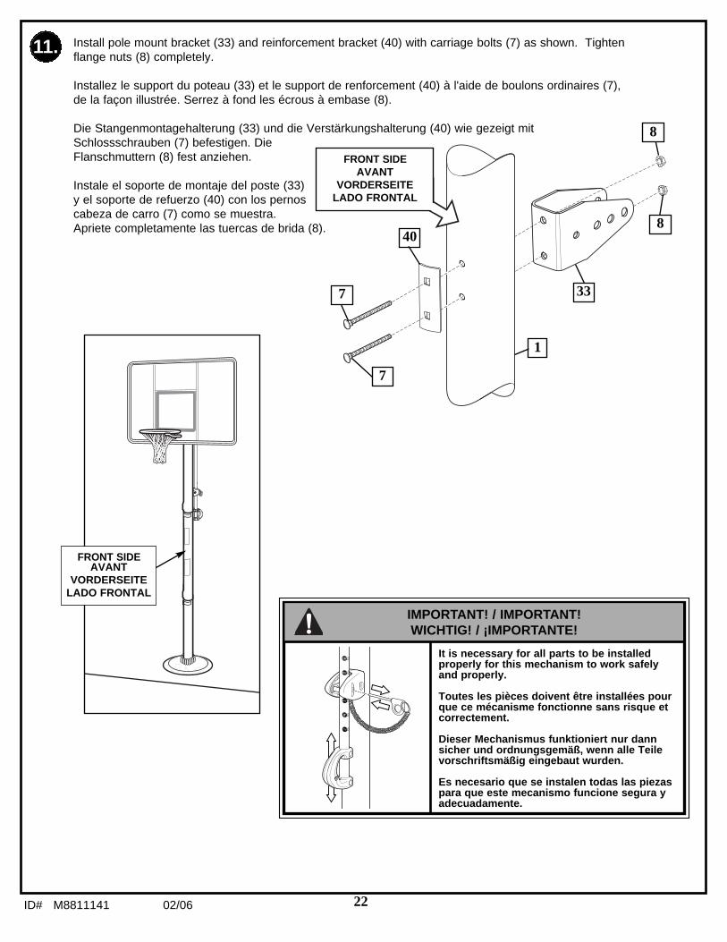
22ID# M8811141 02/06
FRONT SIDEAVANT
VORDERSEITELADO FRONTAL
11. Install pole mount bracket (33) and reinforcement bracket (40) with carriage bolts (7) as shown. Tightenflange nuts (8) completely.
Installez le support du poteau (33) et le support de renforcement (40) à l'aide de boulons ordinaires (7),de la façon illustrée. Serrez à fond les écrous à embase (8).
Die Stangenmontagehalterung (33) und die Verstärkungshalterung (40) wie gezeigt mitSchlossschrauben (7) befestigen. DieFlanschmuttern (8) fest anziehen.
Instale el soporte de montaje del poste (33)y el soporte de refuerzo (40) con los pernoscabeza de carro (7) como se muestra.Apriete completamente las tuercas de brida (8).
1
40
7
7 33
8
8
FRONT SIDEAVANT
VORDERSEITELADO FRONTAL
It is necessary for all parts to be installedproperly for this mechanism to work safelyand properly.
Toutes les pièces doivent être installées pourque ce mécanisme fonctionne sans risque etcorrectement.
Dieser Mechanismus funktioniert nur dannsicher und ordnungsgemäß, wenn alle Teilevorschriftsmäßig eingebaut wurden.
Es necesario que se instalen todas las piezaspara que este mecanismo funcione segura yadecuadamente.
IMPORTANT! / IMPORTANT!WICHTIG! / ¡IMPORTANTE!

02/06 ID# M881114123
Attach spacers (12, 13) to pole mount bracket (33) with bolts (9), washers (10), and lock nuts (11)as shown.
Fixez les entretoises (12, 13) sur le support de poteau (33) au moyen de boulons (9), de rondelles(10) et d'écrous (11), de la façon illustrée.
Die Abstandsstücke (12, 13) wie gezeigt mit Schrauben (9), Unterlegscheiben (10) undGegenmuttern (11) an der Stangenmontagehalterung (33) befestigen.
Conecte los espaciadores (12, 13) en el soporte de montaje del poste (33) usando pernos (9),arandelas (10) y contratuercas (11) como se muestra.
12
33
1213
13
11
9
1010
12.
Tighten just until washers (10) stopmoving.
Serrez seulement jusqu'à ce que lesrondelles (10) cessent de tourner.
Nur so weit anziehen, bis sich dieUnterlegscheiben (10) nicht mehrbewegen.
Apriete lo suficiente para que lasarandelas (10) no se muevan.
IMPORTANT!IMPORTANT!
WICHTIG!¡IMPORTANTE!

24ID# M8811141 02/06
Assemble lanyard (17) to locking pin (16) as shown (FIG A). Attach covers (14) onto pole mountbracket (33) with carriage bolt (15) and nut (8) as shown.
Assemblez le cordon (17) et la goupille de blocage (16) de la façon illustrée. Fixez les couvre-supports (14) sur le support de poteau (33) à l'aide d'un boulon ordinaire (15) et d'un écrou (8),de la façon illustrée.
Die Leine (17) wie gezeigt (Abb. A) am Verriegelungsstift (16) befestigen. Die Abdeckungen (14)mit der Schlossschraube (15) und Mutter (8) wie gezeigt an der Stangenmontagehalterung (33)befestigen.
Monte el acollador (17) en el perno de fijación (16) como semuestra (FIG A). Coloque las cubiertas (35) en el soporte demontaje del poste (33) con un pernocabeza de carro (15) y unatuerca (8) como se muestra.
33
8
14
14
17
15
13.
16
15
FIG. AFIG. A
ABB. AFIG. A
17
16
IMPORTANT!IMPORTANT!
WICHTIG!¡IMPORTANTE!
DO NOT OVER TIGHTEN!
NE SERREZ PAS TROP!
NICHT ZU FEST ANZIEHEN!
¡NO APRIETE EXCESIVAMENTE!
Loop end of pin lanyard over carriage bolt as itpasses through the pole mount bracket duringthis assembly (see Fig. A).
Durant le montage, enfilez le boulon ordinairedans l'extrémité du cordon avant de le fairepasser dans le support de poteau (voir figure A).
Während dieses Montageschritts das Ende derStiftleine über die Schlossschraube schlingen,wenn diese durch die Stangenmontagehalterunggeschoben wird (siehe Abb. A).
Inserte el extremo del acollador del pasadorsobre el perno cabeza de carro conforme pasa através del soporte del montaje del poste duranteeste montaje, vea la FIG. A.
IMPORTANT!IMPORTANT!
WICHTIG!¡IMPORTANTE!
15
17
33
14
8 14
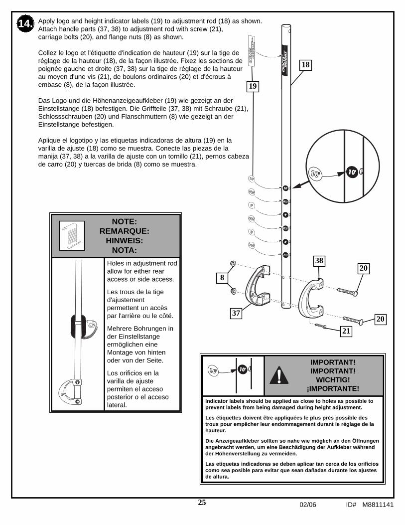
02/06 ID# M881114125
Apply logo and height indicator labels (19) to adjustment rod (18) as shown.Attach handle parts (37, 38) to adjustment rod with screw (21),carriage bolts (20), and flange nuts (8) as shown.
Collez le logo et l'étiquette d'indication de hauteur (19) sur la tige deréglage de la hauteur (18), de la façon illustrée. Fixez les sections depoignée gauche et droite (37, 38) sur la tige de réglage de la hauteurau moyen d'une vis (21), de boulons ordinaires (20) et d'écrous àembase (8), de la façon illustrée.
Das Logo und die Höhenanzeigeaufkleber (19) wie gezeigt an derEinstellstange (18) befestigen. Die Griffteile (37, 38) mit Schraube (21),Schlossschrauben (20) und Flanschmuttern (8) wie gezeigt an derEinstellstange befestigen.
Aplique el logotipo y las etiquetas indicadoras de altura (19) en lavarilla de ajuste (18) como se muestra. Conecte las piezas de lamanija (37, 38) a la varilla de ajuste con un tornillo (21), pernos cabezade carro (20) y tuercas de brida (8) como se muestra.
20
19
38
37
21
18
14.
20
8
Indicator labels should be applied as close to holes as possible toprevent labels from being damaged during height adjustment.
Les étiquettes doivent être appliquées le plus près possible destrous pour empêcher leur endommagement durant le réglage de lahauteur.
Die Anzeigeaufkleber sollten so nahe wie möglich an den Öffnungenangebracht werden, um eine Beschädigung der Aufkleber währendder Höhenverstellung zu vermeiden.
Las etiquetas indicadoras se deben aplicar tan cerca de los orificioscomo sea posible para evitar que sean dañadas durante los ajustesde altura.
IMPORTANT!IMPORTANT!
WICHTIG!¡IMPORTANTE!
Holes in adjustment rodallow for either rearaccess or side access.
Les trous de la tiged'ajustementpermettent un accèspar l'arrière ou le côté.
Mehrere Bohrungen inder Einstellstangeermöglichen eineMontage von hintenoder von der Seite.
Los orificios en lavarilla de ajustepermiten el accesoposterior o el accesolateral.
NOTE:REMARQUE:
HINWEIS:NOTA:

26ID# M8811141 02/06
15.
16
Insert handle assembly through pole mount assembly as shown. Lockpole assembly in place at the 10’ (3.05 m) mark with pin (16).
Insérez la poignée assemblée dans le support de poteau, de la façonillustrée. Bloquez le poteau en position à 3,05 m (10 pieds) à l'aide de lagoupille (16).
Die Griffbaugruppe wie gezeigt durch Stangenmontageeinheit schieben.Den Stangenaufbau mit dem Stift (16) an der 3,05-m- (10-Fuß)-Markierung sichern.
Introduzca el conjunto de la manija a través del conjunto de montaje delposte, como se muestra. Fije el conjunto del poste en su lugar en lamarca de los 10' (3.05 m) con el pasador (16).
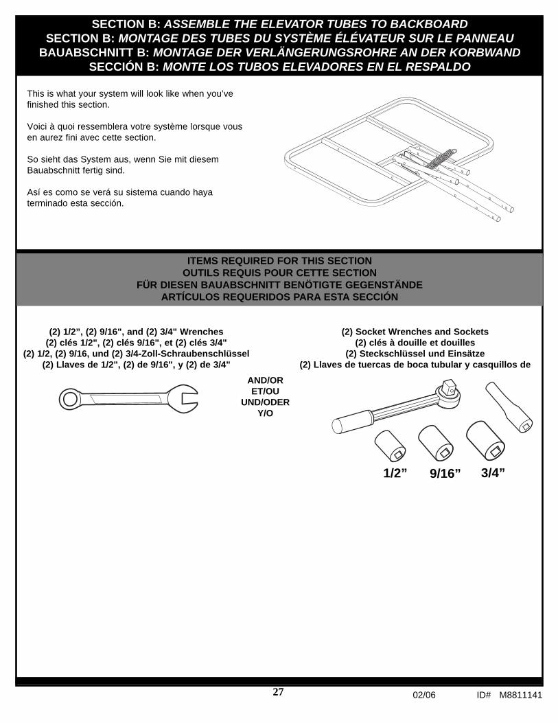
02/06 ID# M881114127
This is what your system will look like when you’vefinished this section.
Voici à quoi ressemblera votre système lorsque vousen aurez fini avec cette section.
So sieht das System aus, wenn Sie mit diesemBauabschnitt fertig sind.
Así es como se verá su sistema cuando hayaterminado esta sección.
SECTION B: ASSEMBLE THE ELEVATOR TUBES TO BACKBOARDSECTION B: MONTAGE DES TUBES DU SYSTÈME ÉLÉVATEUR SUR LE PANNEAU
BAUABSCHNITT B: MONTAGE DER VERLÄNGERUNGSROHRE AN DER KORBWANDSECCIÓN B: MONTE LOS TUBOS ELEVADORES EN EL RESPALDO
ITEMS REQUIRED FOR THIS SECTIONOUTILS REQUIS POUR CETTE SECTION
FÜR DIESEN BAUABSCHNITT BENÖTIGTE GEGENSTÄNDEARTÍCULOS REQUERIDOS PARA ESTA SECCIÓN
9/16”1/2” 3/4”
(2) 1/2”, (2) 9/16", and (2) 3/4" Wrenches(2) clés 1/2", (2) clés 9/16", et (2) clés 3/4"
(2) 1/2, (2) 9/16, und (2) 3/4-Zoll-Schraubenschlüssel(2) Llaves de 1/2", (2) de 9/16", y (2) de 3/4"
(2) Socket Wrenches and Sockets(2) clés à douille et douilles
(2) Steckschlüssel und Einsätze(2) Llaves de tuercas de boca tubular y casquillos de
AND/ORET/OU
UND/ODERY/O

28ID# M8811141 02/06
Assemble backboard brackets (25) using bolts (26), and nuts (11) as shown.
Assemblez les supports de panneau (25) à l’aide des boulons (26) et des écrous (11), comme illustré.
Korbwandklammern (25) wie gezeigtmit Schrauben (26) und Muttern (11)zusammenbauen.
Monte los soportes del respaldo (25)usando pernos (26) y tuercas (11)como se muestra.
2.
25
30Upper Elevator tube
28
Lower Elevator tube
Identify elevator tubes (28, 30).
Identifiez les tubes du système élévateur (28, 30).
Die Verlängerungsrohre (28, 30) zurecht legen.
Identifique los tubos elevadores (28, 30).
Toward PoleVers le poteauZur Stange hinHacia el poste
Toward BoardVers le panneau
Zur Korbwand hinHacia el tablero
11
25
26
11
26
NOTE ORIENTATION.
NOTEZ L'ORIENTATION.
DIE KORREKTEAUSRICHTUNG BEACHTEN.
NOTE LA ORIENTACIÓN.
25
1.

02/06 ID# M881114129
3.
27 29
22 22
25 24
Attach lower elevator tubes (28) and counter balance springs (29) to backboard support brackets (25) usingspacers (22), bolt (27), and nut (24) as shown. Insert T-bolt (42) through Slam Jam bracket (41) as shown.Secure Slam Jam bracket (41) to backboard. Using bolt (47) and nut (8) as shown.
Fixez les tubes inférieurs du dispositif élévateur (28) et le ressort d'équilibrage (29) sur les supports dupanneau (25) à l'aide d'entretoises (22), d'un boulon (27) et d'un écrou (24), de la façon illustrée. Insérez leboulon à T (42) dans le support Slam Jam (41), comme illustré. Fixez le support Slam Jam (41) sur lepanneau en utilisant le boulon ordinaire (47) et l'écrou (8), comme illustré.
Die unteren Verlängerungsrohre (28) und die Gegengewichtsfeder (29) wie gezeigt mit Abstandsstücken (22),Schraube (27) und Mutter (24) an den Korbwandstützklammern (25) befestigen. Die T-Nutenschraube (42)wie gezeigt durch die Slam Jam-Halterung (41) stecken. Die Slam Jam-Halterung (41) an der Korbwandbefestigen. Dazu wie gezeigt die Schraube (47) und die Mutter (8) verwenden.
Conecte los tubos elevadores inferiores (28) y el resorte de contrapeso (29) en los soportes del respaldo (25)usando espaciadores (22) pernos (27) y tuercas (24) como se muestra. Introduzca un perno T (42) a travésdel soporte Slam Jam (41) como se muestra. Fije los conjuntos del soporte Slam Jam (41) en el respaldo.Utilizando el perno (47) y la arandela (8) como se muestra.
29
28
28
8
42
41
47
47 42
41

30ID# M8811141 02/06
2224
28
28
30
27
25
30
4.
2922
Attach upper elevator tubes (30) to backboard support brackets (25) using spacers (22), bolt (27), and nut(24) as shown.
Fixez les tubes supérieurs du dispositif élévateur (30) sur les supports du panneau (25) à l'aided'entretoises (22), d'un boulon (27) et d'un écrou (24), de la façon illustrée.
Die oberen Verlängerungsrohre (30) wie gezeigt mit Abstandsstücken (22), Schraube (27) und Mutter (24)an den Korbwandstützklammern (25) befestigen.
Conecte los tubos elevadores superiores (30) en los soportes del respaldo (25) usando espaciadores (22)pernos (27) y tuercas (24) como se muestra.

02/06 ID# M881114131
SECTION C: ASSEMBLE THE ELEVATOR SYSTEM and BACKBOARDSECTION C: MONTAGE DU SYSTÈME ÉLÉVATEUR ET DU PANNEAU
BAUABSCHNITT C: ZUSAMMENBAU VON VERLÄNGERUNGSVORRICHTUNG UND KORBWANDSECCIÓN C: MONTAJE DEL SISTEMA DEL ELEVADOR Y EL RESPALDO
ITEMS REQUIRED FOR THIS SECTIONOUTILS REQUIS POUR CETTE SECTION
FÜR DIESEN BAUABSCHNITT BENÖTIGTE GEGENSTÄNDEARTÍCULOS REQUERIDOS PARA ESTA SECCIÓN
Phillips-Head ScrewdriverTournevis cruciforme
KreuzschlitzschraubenzieherDestornillador Phillips
Container to MixRécipient pour mélanger
Behälter zum MischenRecipiente para mezclar
This is what your system will look like when you’ve finishedthis section.
Voici à quoi ressemblera votre système lorsque vous enaurez fini avec cette section.
So sieht das System aus, wenn Sie mit diesemBauabschnitt fertig sind.
Así es como se verá su sistema cuando haya terminadoesta sección.
CONCRETEBÉTONBÉTON
CONCRETO
3/4”
(2) 3/4” Wrenches(2) clés 3/4"
(2) 3/4-Zoll-Schraubenschlüssel(2) Llaves de 3/4"
(2) Socket Wrenches and Sockets(2) clés à douille et douilles
(2) Steckschlüssel und Einsätze(2) Llaves de tuercas de boca tubular y casquillos deAND/OR
ET/OUUND/ODER
Y/O
Heavy Duty Taper\Ruban extra-fort
Hochstrapazierfähiges KlebebandCinta adhesiva fort

32ID# M8811141 02/06
Support pole on sawhorse. Attach upper and lower elevator tubes (28, 30) to upper pole section (1) usingbolts (27) and nuts (24) as shown.
Appuyez le poteau sur le banc de sciage.Attachez les tubes supérieurs et inférieurs del'élévateur (28, 30) à la section de poteausupérieure (1) à l'aide des boulons (27) et desécrous (24), comme illustré.
Die Stange auf einen Sägebock legen. Die oberenund unteren Verlängerungsrohre (28, 30) wiegezeigt mit Schrauben (27) und Muttern (24) amoberen Stangenteil (1) befestigen.
Apoye el poste en un caballete de aserrar.Conecte los tubos elevadores superiores einferiores (28, 30) en la sección superior del poste(1) usando pernos (27) y tuercas (24) como semuestra.
1.
1
24
30
30
23
23
23
23
24
28
28
2727
WARNING!AVERTISSEMENT!
WARNUNG!¡ADVERTENCIA!
USE CAUTION; ELEVATOR ASSEMBLY IS HEAVY. TWOCAPABLE ADULTS REQUIRED FOR THIS PROCEDURE.FAILURE TO FOLLOW THIS WARNING COULD RESULTIN SERIOUS INJURY AND/OR PROPERTY DAMAGE.
SOYEZ PRUDENT, CAR LE SYSTÈME ÉLÉVATEUR ESTLOURD. DEUX ADULTES CAPABLES REQUIS POURCETTE PROCÉDURE. SUIVEZ CET AVERTISSEMENTSOUS PEINE D'ENCOURIR DES BLESSURES GRAVESET/OU DES DÉGÂTS MATÉRIELS.
BITTE VORSICHTIG ZU WERKE GEHEN; DIEVERLÄNGERUNGSBAUGRUPPE IST SEHR SCHWER.DIESER VERFAHRENSSCHRITT MUSS VON ZWEI DAZUIN DER LAGE BEFINDLICHEN PERSONENAUSGEFÜHRT WERDEN. EIN MISSACHTEN DIESERWARNUNG KANN ZU SCHWEREN VERLETZUNGENUND/ODER SACHSCHÄDEN FÜHREN.
TENGA CUIDADO; EL CONJUNTO DEL ELEVADOR ESPESADO. SE REQUIEREN DOS ADULTOS CAPACESPARA REALIZAR ESTE PROCEDIMIENTO. SI NO SEOBSERVA ESTA ADVERTENCIA SE PODRÍAOCASIONAR UNA LESIÓN GRAVE Y/O DAÑOS A LAPROPIEDAD.

02/06 ID# M881114133
2.
NOTE:REMARQUE:
HINWEIS:NOTA:
Before going on to next step, set adjustablesystem assembly to the 10’ (3.05 m) setting.
Avant de passer au point suivant, réglez lesystème de réglage en hauteur à 25.4 cm (10po).
Bevor zum nächsten Schritt übergegangen wird,ist das Einstellsystem auf die 3.05-m- (10 Zoll)-Markierung einzustellen.
Antes de continuar con el siguiente paso, ajusteel conjunto del sistema de ajuste en la marcade los 3.05 m (10’).
Install handle assembly to lower elevator tubes (28) using bolt (27), spacers (39), and nut (24) as shown.
Installez la poignée sur les tubes inférieurs du dispositif élévateur (28) au moyen d'un boulon (27),d'entretoises (39) et d'un écrou (24), de la façon illustrée.
Die Griffeinheit wie gezeigt mit Schraube (27), Abstandsstücken (39) und Mutter (24) an den unterenVerlängerungsrohren (28) anbringen.
Instale el conjunto de la manija en los tubos elevadores inferiores (28) usando el perno (27), espaciadores(39) y la tuerca (24) como se muestra.
2728
28
24
39
39

34ID# M8811141 02/06
Install Slam Jam Rim to Backboard
Installez le cerceau Slam Jam sur le panneau.
Den Slam Jam-Korbrand an der Korbwand befestigen.
Instale el borde Slam Jam en el respaldo
A. Fit rim (32) securely into bracket (41) as shown. Allow T-bolt (42) to slip through center holein rim (32).
B. Install reinforcement bracket (43) onto T bolt (42) as shown.C. Install spring (44) onto T bolt (42) as shown.D. Install special nut (46) and washer (45) onto T bolt (42).E. Tighten nut (46) until flush with end of T bolt (42).
A. Calez bien le cerceau (32) dans le support (41), comme illustré. Laissez glisser le boulon à T (42) àtravers le trou central du cerceau (32).
B. Installez le support de renforcement (43) sur le boulon à T (42), comme illustré.C. Installez le ressort (44) sur le boulon à T (42), comme illustré.D. Installez l'écrou spécial (46) et la rondelle (45) sur le boulon à T (42).E. Serrez l'écrou (46) jusqu'à ce qu'il se trouve au même niveau que l'extrémité du boulon à T (42).
A. Den Korbrand (32) wie gezeigt in die Halterung (41) einsetzen. Die T-Nutenschraube (42) gleitet durchdas mittlere Loch im Korbrand (32).
B. Die Verstärkungshalterung (43) wie gezeigt über die T-Nutenschraube (42) schieben.C. Die Feder (44) wie gezeigt auf der T-Nutenschraube (42) anbringen.D. Die Spezialmutter (46) und Unterlegscheibe (45) auf der T-Nutenschraube (42) anbringen.E. Die Mutter (46) anziehen, bis sie bündig mit dem Ende der T-Nutenschraube (42) abschließt.
A. Ajuste el borde (32) seguramente en el soporte (41) como se muestra. Permita que el pernoen "T" (42) se deslice a través del orificio central del borde (32).
B. Instale el soporte de refuerzo (43) en el perno "T" (42) como se muestra.C. Instale el resorte (30) en el perno T (42) como se muestra.D. Instale la tuerca especial (46) y la arandela (45) en el perno T (42).E. Apriete la tuerca (46) hasta que quede al ras del extremo del perno T (42).
3. A

02/06 ID# M881114135
43
46 45
41
42
32
44
42
45
46
A B
C
D
E
42
42
Install Slam Jam Rim to BackboardInstallez le cerceau Slam Jam sur le panneau.
Den Slam Jam-Korbrand an der Korbwand befestigen.Instale el borde Slam Jam en el respaldo
3. B

36ID# M8811141 02/06
4. Insert bolt (27) through left side upper elevator tube (30), then stretch springs (29) onto bolt (27). Insert bolt (27)through right side upper elevator tube (30) and secure with nut (24).
Enfilez le boulon (27) dans le tube supérieur gauche du dispositif élévateur (30), puis tendez le ressort (29) sur leboulon (27). Enfilez le boulon (27) dans le tube supérieur droit du dispositif élévateur (30), puis bloquez le boulonavec l'écrou (24).
Die Schraube (27) durch das linke obere Verlängerungsrohr (30) schieben und die Feder (29) über die Schraube(27) dehnen. Die Schraube (27) durch das rechte obere Verlängerungsrohr (30) schieben und mit der Mutter (24)sichern.
Introduzca el perno (27) a través del tubo elevador superior del lado izquierdo (30), luego estire el resorte (29)hasta el perno (27). Introduzca el perno (27) a través del tubo elevador superior del lado derecho (30) y asegurecon la tuerca (24).
24
27
30
30
29
WARNING!AVERTISSEMENT!
WARNUNG!¡ADVERTENCIA!
USE EYE PROTECTION WHEN INSTALLINGSPRINGS.
PROTÉGEZ-VOUS LES YEUX LORSQUEVOUS INSTALLEZ DES RESSORTS.
BEIM ANBRINGEN DER FEDERNAUGENSCHUTZ TRAGEN!
CUANDO INSTALE LOS RESORTES UTILICEPROTECTORES OCULARES.

02/06 ID# M881114137
6.
5.
48
49
48
48
49
3
2"
3"
Assemble rebar centering clips (48) near top and bottom ofrebar (49) as shown.
Assemblez les entretoises de centrage de la barred'armature (48) près du haut et du bas de la barre (49),comme illustré.
Die zur Zentrierung der Versteifungsstange (48) dienendenAbstandsstücke wie gezeigt in der Nähe des oberen undunteren Endes der Stange (49) anbringen.
Monte los separadores de centramiento de la barra derefuerzo (48) cerca de las partes superior e inferior de labarra de refuerzo (49) como se muestra.
Place rebar with spacers into bottom polesection (3) as shown.
Placez une barre d'armature dans la sectionde poteau inférieure (3) comme illustré.
Die Versteifungsstange wie gezeigt in dasuntere Stangenteil (3) schieben.
Coloque la barra de refuerzo con losseparadores en la sección inferior del poste(3) como se muestra.
Reinforcement Bar
Barre d'armature
Versteifungsstange
Barra de refuerzo

38ID# M8811141 02/06
7.
Heavy-Duty Tape (Not Included)Ruban extra-fort (non fourni)
Hochstrapazierfähiges Klebeband (nicht im Lieferumfang enthalten)Cinta para uso pesado (No se incluye)
Seal hole at the bottom of the bottom pole with heavy-duty tape (not included) to retain rebar (49) andconcrete inside.
Bouchez le trou en bas de la section de poteau inférieure avec du ruban adhésif extra-fort (non fourni)pour retenir la barre d'armature (49) et le béton à l'intérieur.
Das Loch am unteren Ende des unteren Stangenteils mit hochstrapazierfähigem Klebeband (nicht imLieferumfang enthalten) abdichten, um die Versteifungsstange (49) und den Beton im Innern der Stangezu sichern.
Selle el orificio que se encuentra en la parte inferior de la sección inferior del poste con cinta para usopesado (no se incluye) a fin de fijar en el interior la barra de refuerzo (49) y el concreto.
49
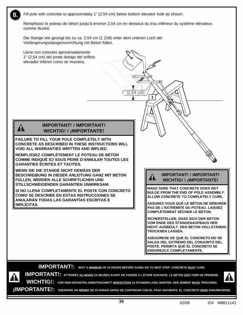
02/06 ID# M881114139
8.
IMPORTANT!: WAIT A MINIMUM OF 24 HOURS BEFORE GOING ON TO NEXT STEP. CONCRETE MUST CURE.
IMPORTANT!: ATTENDEZ AU MOINS 24 HEURES AVANT DE PASSER À L'ÉTAPE SUIVANTE. LE BÉTON DOIT FINIR DE PRENDRE.
WICHTIG!: VOR DEM NÄCHSTEN ARBEITSSCHRITT MINDESTENS 24 STUNDEN LANG WARTEN. DER ZEMENT MUSS TROCKNEN.
¡IMPORTANTE!: ESESPERE UN MÍNIMO DE 24 HORAS ANTES DE CONTINUAR CON EL PASO SIGUIENTE. EL CONCRETO DEBE ENDURECERSE.
Fill pole with concrete to approximately 1” (2.54 cm) below bottom elevator hole as shown.
Remplissez le poteau de béton jusqu'à environ 2,54 cm en dessous du trou inférieur du système élévateur,comme illustré.
Die Stange wie gezeigt bis zu ca. 2,54 cm (1 Zoll) unter dem unteren Loch derVerlängerungsstangenvorrichtung mit Beton füllen.
Llene con concreto aproximadamente 1" (2,54 cm) del poste debajo del orificioelevador inferior como se muestra.
FAILURE TO FILL YOUR POLE COMPLETELY WITHCONCRETE AS DESCRIBED IN THESE INSTRUCTIONS WILLVOID ALL WARRANTIES WRITTEN AND IMPLIED.
REMPLISSEZ COMPLÈTEMENT LE POTEAU DE BÉTONCOMME INDIQUÉ ICI SOUS PEINE D'ANNULER TOUTES LESGARANTIES ÉCRITES ET TACITES.
WENN SIE DIE STANGE NICHT GEMÄSS DERBESCHREIBUNG IN DIESER ANLEITUNG GANZ MIT BETONFÜLLEN, WERDEN ALLE SCHRIFTLICHEN UNDSTILLSCHWEIGENDEN GARANTIEN UNWIRKSAM.
SI NO LLENA COMPLETAMENTE EL POSTE CON CONCRETOCOMO SE DESCRIBE EN ESTAS INSTRUCCIONES SEANULARÁN TODAS LAS GARANTÍAS ESCRITAS EIMPLÍCITAS.
IMPORTANT! / IMPORTANT!WICHTIG! / ¡IMPORTANTE!
MAKE SURE THAT CONCRETE DOES NOTBULGE FROM THE END OF POLE ASSEMBLY.ALLOW CONCRETE TO COMPLETELY CURE.
ASSUREZ-VOUS QUE LE BÉTON NE DÉBORDEPAS DE L'EXTRÉMITÉ DU POTEAU. LAISSEZCOMPLÈTEMENT SÉCHER LE BÉTON.
SICHERSTELLEN, DASS SICH DER BETONVOM ENDE DES STANGENAUFBAUS HERNICHT AUSBEULT. DEN BETON VOLLSTÄNDIGTROCKNEN LASSEN.
ASEGÚRESE DE QUE EL CONCRETO NO SESALGA DEL EXTREMO DEL CONJUNTO DELPOSTE. PERMITA QUE EL CONCRETO SEENDUREZCA COMPLETAMENTE.
IMPORTANT! / IMPORTANT!WICHTIG! \ ¡IMPORTANTE!
1

40ID# M8811141 02/06
9. Install net (34).
Installez le filet (34).
Das Netz (34) anbringen.
Instale la red (34).
3234
34
OUTSIDE VIEW
Net InstallationInstallation Du Filry
Anbringung Des NetzesInstalación De La Red
A B
C D

02/06 ID# M881114141
SECTION D: UPRIGHT, SECURE AND USE POLE SYSTEMSECTION D : REDRESSEMENT, FIXATION ET UTILISATION DU POTEAU
BAUABSCHNITT D: AUFRICHTEN, SICHERN UND VERWENDEN DES STANGENSYSTEMSSECCIÓN D: LEVANTE, ASEGURE Y USE EL SISTEMA DEL POSTE
This is what your system will look like when you’ve finished thissection.
Voici à quoi ressemblera votre système lorsque vous en aurez finiavec cette section.
So sieht das System aus, wenn Sie mit diesem Bauabschnitt fertigsind.
Así es como se verá su sistema cuando haya terminado estasección.
WedgeCaleKeil
Cuña
HammerMarteauHammerMartillo
ITEMS REQUIRED FOR THIS SECTIONOUTILS REQUIS POUR CETTE SECTION
FÜR DIESEN BAUABSCHNITT BENÖTIGTE GEGENSTÄNDEARTÍCULOS REQUERIDOS PARA ESTA SECCIÓN

42ID# M8811141 02/06
2.
1.
5
36
WARNING!AVERTISSEMENT!
WARNUNG!¡ADVERTENCIA!
USE CAUTION; ELEVATOR ASSEMBLY IS HEAVY. TWOCAPABLE ADULTS REQUIRED FOR THIS PROCEDURE.FAILURE TO FOLLOW THIS WARNING COULD RESULTIN SERIOUS INJURY AND/OR PROPERTY DAMAGE.
SOYEZ PRUDENT, CAR LE SYSTÈME ÉLÉVATEUR ESTLOURD. DEUX ADULTES CAPABLES REQUIS POURCETTE PROCÉDURE. SUIVEZ CET AVERTISSEMENTSOUS PEINE D'ENCOURIR DES BLESSURES GRAVESET/OU DES DÉGÂTS MATÉRIELS.
BITTE VORSICHTIG ZU WERKE GEHEN; DIEVERLÄNGERUNGSBAUGRUPPE IST SEHR SCHWER.DIESER VERFAHRENSSCHRITT MUSS VON ZWEI DAZUIN DER LAGE BEFINDLICHEN PERSONENAUSGEFÜHRT WERDEN. EIN MISSACHTEN DIESERWARNUNG KANN ZU SCHWEREN VERLETZUNGENUND/ODER SACHSCHÄDEN FÜHREN.
TENGA CUIDADO; EL CONJUNTO DEL ELEVADOR ESPESADO. SE REQUIEREN DOS ADULTOS CAPACESPARA REALIZAR ESTE PROCEDIMIENTO. SI NO SEOBSERVA ESTA ADVERTENCIA SE PODRÍAOCASIONAR UNA LESIÓN GRAVE Y/O DAÑOS A LAPROPIEDAD.
After concrete has cured, remove tape, install pole cap (36), fit pole assembly intosleeve (5).
Une fois que le béton a pris, retirez le ruban, installez le capuchon du poteau (36),puis calez le poteau dans son manchon (5).
Nach dem Trocknen des Zements das Klebeband entfernen, die Stangenkappe (36)aufsetzen, und den Stangenaufbau in die Muffe (5) einsetzen.
Después de que el concreto se haya endurecido, quite la cinta, instale la tapa delposte (36), coloque el conjunto del poste en la manga (5).
Use a wedge to gently tap cap of ground sleeve (5) until tight.
Utilisez la cale pour tapoter sur le capuchon du manchon (5)jusqu'à ce qu'il soit bien fixé.
Mit einem Keil leicht gegen die Abdeckung der Bodenmuffe (5) klopfen, bis diese fest sitzt.
Use la cuña para golpear suavemente la tapa de la mangadel piso (5) hasta que quede ajustada.
5
PLAYING SURFACESURFACE DE JEU
SPIELFLÄCHESUPERFICIE DE JUEGO

02/06 ID# M881114143
16
3.
WARNING!AVERTISSEMENT!
WARNUNG!¡ADVERTENCIA!
DO NOT ALLOW CHILDREN TO ADJUSTHEIGHT.
INTERDISEZ À UN ENFANT DE RÉGLERLA HAUTEUR.
KINDERN DARF DAS VERSTELLEN DERHÖHE NICHT GESTATTET WERDEN.
NO PERMITA QUE LOS NIÑOSAJUSTEN LA ALTURA.
While holding handle, remove pin (16).
Tout en tenant la poignée, retirez la goupille (16).
Bei festgehaltenem Griff den Stift (16) herausziehen.
Mientras sujeta la agarradera, quite el perno (16).
Move elevator up or down to desired height.
Remontez ou abaissez le levier à la hauteur de votre choix.
Den Hebel auf die gewünschte Höhe anheben oder absenken.
Eleve o baje la palanca hasta la altura deseada.
Replace pin (16) full length to lock system at desired height.
Relâchez la poignée en vous assurant que la goupille (16) estbloquée dans la fente.
Den Griff loslassen und sicherstellen, daß der Stift (16) fest imSchlitz einrastet.
Libere la agarradera asegurándose de que el pasador (16)quede fijo en la ranura.
A
B
C
B
C
A

44ID# M8811141 02/06
4.Apply height adjustment label (35) to front of pole as shown. Regulation rim height is 10 feet (3.05 m).
Collez l'étiquette d'échelle de hauteur (35) sur l'avant du poteau, comme illustré. La hauteur réglementaire ducerceau est 3,05 m (10 pieds).
Höhenkleber (35) wie gezeigt an der Vorderseite derStange anbringen. Die offizielle Korbrandhöhe beträgt 3,05m (10 Fuß).
Aplique las calcomanías de altura (35) en el frente delposte como se muestra. La altura reglamentaria del bordees de 3.05m (10 pies).
NOTE:REMARQUE:
HINWEIS:NOTA:
Peel protective film from surface ofacrylic backboard prior to use.
Décollez le film de protection de lasurface du panneau en acryliqueavant usage.
Vor Gebrauch die Schutzfolie vonder Oberfläche der Akryl-Korbwandabziehen.
Desprenda la película protectorade la superficie del respaldo deacrílico antes de usarlo.
10 ft.(3.05 m)
2
2
1
3
201251 2/99
HEIGHT ADJUSTMENT
TO ADJUST BACKBOARD:
1. While holding handle, remove pin.
2. Move elevator up or down todesired height.
3. Replace pin full length to lock system at desired height.
31


