SGH100-TFM86
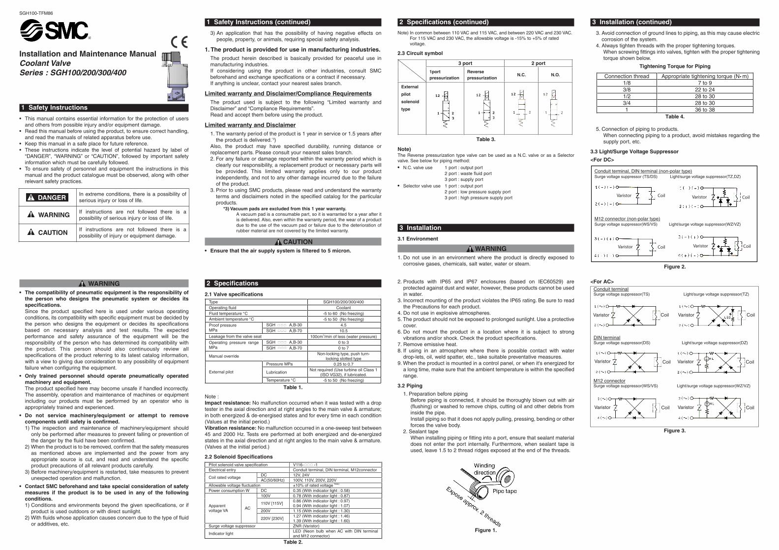
Installation and Maintenance ManualCoolant ValveSeries : SGH100/200/300/400
1 Safety Instructions
• This manual contains essential information for the protection of usersand others from possible injury and/or equipment damage.
• Read this manual before using the product, to ensure correct handling,and read the manuals of related apparatus before use.
• Keep this manual in a safe place for future reference.• These instructions indicate the level of potential hazard by label of
“DANGER”, “WARNING” or “CAUTION”, followed by important safetyinformation which must be carefully followed.
• To ensure safety of personnel and equipment the instructions in thismanual and the product catalogue must be observed, along with otherrelevant safety practices.
WARNING• The compatibility of pneumatic equipment is the responsibility of
the person who designs the pneumatic system or decides itsspecifications.Since the product specified here is used under various operatingconditions, its compatibility with specific equipment must be decided bythe person who designs the equipment or decides its specificationsbased on necessary analysis and test results. The expectedperformance and safety assurance of the equipment will be theresponsibility of the person who has determined its compatibility withthe product. This person should also continuously review allspecifications of the product referring to its latest catalog information,with a view to giving due consideration to any possibility of equipmentfailure when configuring the equipment.
• Only trained personnel should operate pneumatically operatedmachinery and equipment.The product specified here may become unsafe if handled incorrectly.The assembly, operation and maintenance of machines or equipmentincluding our products must be performed by an operator who isappropriately trained and experienced.
• Do not service machinery/equipment or attempt to removecomponents until safety is confirmed.1) The inspection and maintenance of machinery/equipment should
only be performed after measures to prevent falling or prevention ofthe danger by the fluid have been confirmed.
2) When the product is to be removed, confirm that the safety measuresas mentioned above are implemented and the power from anyappropriate source is cut, and read and understand the specificproduct precautions of all relevant products carefully.
3) Before machinery/equipment is restarted, take measures to preventunexpected operation and malfunction.
• Contact SMC beforehand and take special consideration of safetymeasures if the product is to be used in any of the followingconditions. 1) Conditions and environments beyond the given specifications, or if
product is used outdoors or with direct sunlight.2) With fluids whose application causes concern due to the type of fluid
or additives, etc.
1 Safety Instructions (continued)
3) An application that has the possibility of having negative effects onpeople, property, or animals, requiring special safety analysis.
1. The product is provided for use in manufacturing industries.The product herein described is basically provided for peaceful use inmanufacturing industries.If considering using the product in other industries, consult SMCbeforehand and exchange specifications or a contract if necessary.If anything is unclear, contact your nearest sales branch.
Limited warranty and Disclaimer/Compliance RequirementsThe product used is subject to the following “Limited warranty andDisclaimer” and “Compliance Requirements”.Read and accept them before using the product.
Limited warranty and Disclaimer1. The warranty period of the product is 1 year in service or 1.5 years after
the product is delivered.*3)Also, the product may have specified durability, running distance orreplacement parts. Please consult your nearest sales branch.2. For any failure or damage reported within the warranty period which is
clearly our responsibility, a replacement product or necessary parts willbe provided. This limited warranty applies only to our productindependently, and not to any other damage incurred due to the failureof the product.
3. Prior to using SMC products, please read and understand the warrantyterms and disclaimers noted in the specified catalog for the particularproducts.
*3) Vacuum pads are excluded from this 1 year warranty.A vacuum pad is a consumable part, so it is warranted for a year after itis delivered. Also, even within the warranty period, the wear of a productdue to the use of the vacuum pad or failure due to the deterioration ofrubber material are not covered by the limited warranty.
CAUTION• Ensure that the air supply system is filtered to 5 micron.
2 Specifications
2.1 Valve specifications
Note :Impact resistance: No malfunction occurred when it was tested with a droptester in the axial direction and at right angles to the main valve & armature;in both energized & de-energised states and for every time in each condition(Values at the initial period.)Vibration resistance: No malfunction occurred in a one-sweep test between45 and 2000 Hz. Tests ere performed at both energized and de-energizedstates in the axial direction and at right angles to the main valve & armature.(Valves at the initial period.)
2.2 Solenoid Specifications
2 Specifications (continued)
Note) In common between 110 VAC and 115 VAC, and between 220 VAC and 230 VAC.For 115 VAC and 230 VAC, the allowable voltage is -15% to +5% of ratedvoltage.
2.3 Circuit symbol
Note)The Reverse pressurization type valve can be used as a N.C. valve or as a Selectorvalve. See below for piping method:
• N.C. valve use 1 port : output port2 port : waste fluid port 3 port : supply port
• Selector valve use 1 port : output port2 port : low pressure supply port3 port : high pressure supply port
3 Installation
3.1 Environment
WARNING1. Do not use in an environment where the product is directly exposed to
corrosive gases, chemicals, salt water, water or steam.
2. Products with IP65 and IP67 enclosures (based on IEC60529) areprotected against dust and water, however, these products cannot be usedin water.
3. Incorrect mounting of the product violates the IP65 rating. Be sure to readthe Precautions for each product.
4. Do not use in explosive atmospheres.5. The product should not be exposed to prolonged sunlight. Use a protective
cover.6. Do not mount the product in a location where it is subject to strong
vibrations and/or shock. Check the product specifications.7. Remove emissive heat.8. If using in an atmosphere where there is possible contact with water
drop-lets, oil, weld spatter, etc., take suitable preventative measures.9. When the product is mounted in a control panel, or when it's energized for
a long time, make sure that the ambient temperature is within the specifiedrange.
3.2 Piping
1. Preparation before pipingBefore piping is connected, it should be thoroughly blown out with air(flushing) or washed to remove chips, cutting oil and other debris frominside the pipe.Install piping so that it does not apply pulling, pressing, bending or otherforces the valve body.
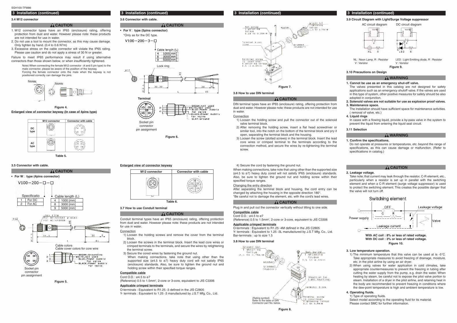
2. Sealant tapeWhen installing piping or fitting into a port, ensure that sealant materialdoes not enter the port internally. Furthermore, when sealant tape isused, leave 1.5 to 2 thread ridges exposed at the end of the threads.
<For AC>
3 Installation (continued)
3. Avoid connection of ground lines to piping, as this may cause electriccorrosion of the system.
4. Always tighten threads with the proper tightening torques.When screwing fittings into valves, tighten with the proper tighteningtorque shown below.
Tightening Torque for Piping
5. Connection of piping to products.When connecting piping to a product, avoid mistakes regarding thesupply port, etc.
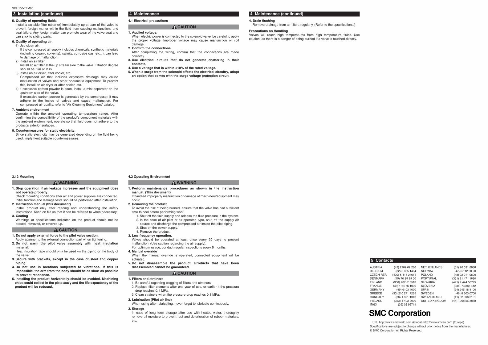
3.3 Light/Surge Voltage Suppressor
<For DC>
In extreme conditions, there is a possibility ofserious injury or loss of life.
WARNING If instructions are not followed there is a possibility of serious injury or loss of life.
CAUTION If instructions are not followed there is a possibility of injury or equipment damage.
DANGER
trop 2 trop 3
1port pressurization
Reverse pressurization
N.C. N.O.
External
pilot
solenoid
type
004/003/002/001HGS epyT tnalooC diulf gnitarepO
Fluid temperature ° )gnizeerf oN( 06 ot 5- CAmbient temperature °C -5 to 50 (No freezing)
SGH A,B-30 4.5Proof pressure MPa SGH A,B-70 10.5Leakage from the valve seat 100cm3/min of less (water pressure)
SGH A,B-30 0 to 3 Operating pressure range MPa SGH A,B-70 0 to 7
Manual override Non-locking type, push turn-
locking slotted type Pressure MPa 0.25 to 0.7
Lubrication Not required (Use turbine oil Class 1
(ISO VG32), if lubricated. External pilot
Temperature °C -5 to 50 (No freezing)
� ��� ��
� ��� ��
Connection thread Appropriate tightening torque (N•m) 9 ot 7 8/1 42 ot 22 8/3 03 ot 82 2/1 03 ot 82 4/3 83 ot 63 1
Conduit terminal, DIN terminal (non-polar type)Surge voltage suppressor (TS/DS) Light/surge voltage suppressor(TZ,DZ)
M12 connector (non-polar type)Surge voltage suppressor(WS/VS) Light/surge voltage suppressor(WZ/VZ)
CoilVaristor CoilVaristor
Varistor Varistor Coil Coil
Conduit terminalSurge voltage suppressor(TS) Light/surge voltage suppressor(TZ)
DIN terminalSurge voltage suppressor(DS) Light/surge voltage suppressor(DZ)
M12 connectorSurge voltage suppressor(WS/VS) Light/surge voltage suppressor(WZ/VZ)
lioC lioCVaristor Varistor
Varistor Varistor lioC lioC
rotsiraV rotsiraV lioC lioC
Pilot solenoid valve specification V116- -1 rotcennoc21M ,lanimret NID ,lanimret tiudnoC yrtne lacirtcelE
DC 12V, 24V Coil rated voltage
AC(50/60Hz) 100V, 110V, 200V, 220V Allowable voltage fluctuation ±10% of rated voltage Note)
Power consumption W DC 0.35 (With indicator light : 0.58) 100V 0.78 (With indicator light : 0.87)
110V [115V] 0.86 (With indicator light : 0.97) 0.94 (With indicator light : 1.07)
200V 1.15 (With indicator light : 1.30) Apparent voltage VA
AC
220V [230V] 1.27 (With indicator light : 1.46) 1.39 (With indicator light : 1.60)
Surge voltage suppressor ZNR (Varistor)
Indicator light LED (Neon bulb when AC with DIN terminal and M12 connector)
� ��
Table 1.
Table 3.
Table 2.
Table 4.
Figure 2.
Figure 3.
Figure 1.
3 Installation (continued)
3.4 M12 connector
CAUTION1. M12 connector types have an IP65 (enclosure) rating, offering
protection from dust and water. However please note: these productsare not intended for use in water.
2. Do not use a tool to mount the connector, as this may cause damage.Only tighten by hand. (0.4 to 0.6 N?m)
3. Excessive stress on the cable connector will violate the IP65 rating.Please use caution and do not apply a stress of 30 N or greater.
Failure to meet IP65 performance may result if using alternativeconnectors than those shown below, or when insufficiently tightened.
Note) When connecting the female M12 connector (4 and 5 pin type) to themale connector, please be aware of the position of the keyway.Forcing the female connector onto the male when the keyway is notpositioned correctly can damage the pins.
Enlarged view of connector keyway (In case of 4pins type)
SGH100-TFM86
3.5 Connector with cable.
CAUTION• For W� type (4pins connector)
3 Installation (continued)
3.6 Connector with cable.
CAUTION• For V� type (5pins connector)
*Only as for the DC type.
Enlarged view of connector keyway
3.7 How to use Conduit terminal
CAUTIONConduit terminal types have an IP65 (enclosure) rating, offering protectionfrom dust and water. However please note: these products are not intendedfor use in water.
Connection1) Loosen the holding screws and remove the cover from the terminal
block.2) Loosen the screws in the terminal block. Insert the lead core wires or
crimped terminals to the terminals, and secure the wires by retighteningthe terminal screw.
3) Secure the cored wires by fastening the ground nut.When making connections, take note that using other than thesupported size (ø4.5 to ø7) heavy duty cord will not satisfy IP65(enclosure) standards. Also, be sure to tighten the ground nut andholding screw within their specified torque ranges.
Compatible cableCord O.D. : ø4.5 to ø7(Reference) 0.5 to 1.5mm2, 2-core or 3-core, equivalent to JIS C3306
Applicable crimped terminalsO-terminals : Equivalent to R1.25 -3 defined in the JIS C2805Y- terminals : Equivalent to 1.25 -3 manufactured by J.S.T Mfg. Co., Ltd.
3 Installation (continued)
3.8 How to use DIN terminal
CAUTIONDIN terminal types have an IP65 (enclosure) rating, offering protection fromdust and water. However please note: these products are not intended for usein water.
Connection1) Loosen the holding screw and pull the connector out of the solenoid
valve terminal block.2) After removing the holding screw, insert a flat head screwdriver or
similar tool, into the notch on the bottom of the terminal block and pry itopen, separating the terminal block and the housing.
3) Loosen the screw (slotted screws) in the terminal block. Insert the leadcore wires or crimped terminal to the terminals according to theconnection method, and secure the wires by re-tightening the terminalscrew.
4) Secure the cord by fastening the ground nut.When making connections, take note that using other than the supported size(ø4.5 to ø7) heavy duty cored will not satisfy IP65 (enclosure) standards.Also, be sure to tighten the ground nut and holding screw within theirspecified torque ranges.
Changing the entry directionAfter separating the terminal block and housing, the cord entry can bechanged by attaching the housing in the opposite direction 180°.*Be careful not to damage the element, etc. with the cord’s lead wires.
CAUTIONPlug in and pull out the connector vertically without tilting to one side.
Compatible cableCord O.D. : ø4.5 to ø7(Reference) 0.5 to 1.5mm2, 2-core or 3-core, equivalent to JIS C3306
Applicable crimped terminalsO-terminals : Equivalent to R1.25 -4M defined in the JIS C2805Y- terminals : Equivalent to 1.25 -3L manufactured by J.S.T Mfg. Co., Ltd.Bar-terminals : up to size 1.5
3.8 How to use DIN terminal
CAUTION2. Leakage voltage.
Take note; that current may leak through the resistor, C-R element, etc.,particularly when a resistor is set up in parallel with the switchingelement and when a C-R element (surge voltage suppressor) is usedto protect the switching element. This creates the possible danger thatthe valve will not turn off.
With AC coil : 8% or less of rated voltage.With DC coil : 3% or less of rated voltage.
3. Low temperature operation.1) The minimum temperature that this valve can be used at is -5°C.
Take appropriate measures to avoid freezing of drainage, moisture,etc. in the pilot airline by using an air dryer.
2) When using valves for water application in cold climates, takeappropriate countermeasures to prevent the freezing in tubing aftercutting the water supply from the pump, e.g. drain the water. Whenheating by steam, be careful not to expose the pilot valve portion tosteam. Installation of a dryer in the pilot airline, and retaining heat inthe body are recommended to prevent freezing in conditions wherethe dew-point temperature is high and ambient temperature is low.
4. Operating fluids.1) Type of operating fluids.Select model according to the operating fluid for its material.Please contact SMC for further information.
3 Installation (continued)
3.9 Circuit Diagram with Light/Surge Voltage suppressor
3.10 Precautions on Design
WARNING1. Cannot be use as an emergency shut-off valve.
The valves presented in this catalog are not designed for safetyapplications such as an emergency shutoff valve. If the valves are usedin this type of system, other positive measures for safety should be alsoadopted in conjunction.
2. Solenoid valves are not suitable for use as explosion proof valves.3. Maintenance space.
The installation should have sufficient space for maintenance activities.( removal of valve, etc.)
4. Liquid ringsIn cases with a flowing liquid, provide a by-pass valve in the system toprevent the liquid from entering the liquid seal circuit.
3.11 Selection
WARNING1. Confirm the specifications.
Do not operate at pressures or temperatures, etc. beyond the range ofspecifications, as this can cause damage or malfunction. (Refer tospecifications in catalog.)
KeywayKeyway
M12 connector Connector with cable
DCtype
ACtype
Specification
Cable length (L)1 For DC 2 For AC
4 1000 [mm] 8 3000 [mm] 9 5000 [mm]
Cable colorsCable cover colors for core wire
Socket pin connector
pin assignment
Terminal
Lock ring
M12 connector Connector with cable
NL : Neon Lamp, R : Resister LED : Light Emitting diode, R : Resister V : Varistor V : Varistor
AC circuit diagram DC circuit diagram
Socket pinconnector
pin assignment
(Rating symbol) Refer to the table of DIN Connector part No. below.
Figure 4.
Table 5.
Figure 5.
Figure 6.
Table 6.
Figure 7.
Figure 8.
Figure 9.
Figure 10.
3 Installation (continued)
5. Quality of operating fluidsInstall a suitable filter (strainer) immediately up stream of the valve toprevent foreign matter within the fluid from causing malfunctions andseal failure. Any foreign matter can promote wear of the valve seat andcan stick to sliding parts.
6. Quality of operating air.1) Use clean air.
If the compressed air supply includes chemicals, synthetic materials(including organic solvents), salinity, corrosive gas, etc., it can leadto damage or malfunction.
2) Install an air filter.Install an air filter at the up stream side to the valve. Filtration degreeshould be 5ìm or less.
3) Install an air dryer, after cooler, etc.Compressed air that includes excessive drainage may causemalfunction of valves and other pneumatic equipment. To preventthis, install an air dryer or after cooler, etc.
4) If excessive carbon powder is seen, install a mist separator on theupstream side of the valve.If excessive carbon powder is generated by the compressor, it mayadhere to the inside of valves and cause malfunction. Forcompressed air quality, refer to “Air Cleaning Equipment” catalog.
7. Ambient environmentOperate within the ambient operating temperature range. Afterconfirming the compatibility of the product’s component materials withthe ambient environment, operate so that fluid does not adhere to theproduct’s exterior surfaces.
8. Countermeasures for static electricity.Since static electricity may be generated depending on the fluid beingused, implement suitable countermeasures.
SGH100-TFM86
3.12 Mounting
WARNING1. Stop operation if air leakage increases and the equipment does
not operate properly. Check mounting conditions after air and power supplies are connected.Initial function and leakage tests should be performed after installation.
2. Instruction manual (this document)Install product only after reading and understanding the safetyinstructions. Keep on file so that it can be referred to when necessary.
3. CoatingWarnings or specifications indicated on the product should not beerased, removed, or covered up.
CAUTION1. Do not apply external force to the pilot valve section.
Apply spanner to the external connection part when tightening.2. Do not warm the pilot valve assembly with heat insulation
material.Heat insulation tape should only be used on the piping or the body ofthe valve.
3. Secure with brackets, except in the case of steel and copperpiping.
4. Do not use in locations subjected to vibrations. If this isimpossible, the arm from the body should be as short as possibleto prevent resonance.
5. Installing the product horizontally should be avoided. Machiningchips could collect in the plate ass'y and the life expectancy of theproduct will be reduced.
4 Maintenance
4.1 Electrical precautions
CAUTION1. Applied voltage.
When electric power is connected to the solenoid valve, be careful to applythe proper voltage. Improper voltage may cause malfunction or coildamage.
2. Confirm the connections.After completing the wiring, confirm that the connections are madecorrectly.
3. Use electrical circuits that do not generate chattering in theircontacts.
4. Use a voltage that is within ±10% of the rated voltage.5. When a surge from the solenoid affects the electrical circuitry, adopt
an option that comes with the surge voltage protection circuit.
4.2 Operating Environment
WARNING1. Perform maintenance procedures as shown in the instruction
manual. (This document).If handled improperly malfunction or damage of machinery/equipment mayoccur.
2. Removing the productTo avoid the risk of being burned, ensure that the valve has had sufficienttime to cool before performing work.
1. Shut off the fluid supply and release the fluid pressure in the system.2. In the case of air pilot or air-operated type, shut off the supply air
source and discharge the compressed air inside the pilot piping.3. Shut off the power supply.4. Remove the product.
3. Low frequency operation.Valves should be operated at least once every 30 days to preventmalfunction. (Use caution regarding the air supply).For optimum usage, conduct regular inspections every 6 months.
4. Manual overrideWhen the manual override is operated, connected equipment will beactuated.
5. Do not disassemble the product. Products that have beendisassembled cannot be guaranteed.
CAUTION1. Filters and strainers
1. Be careful regarding clogging of filters and strainers.2. Replace filter elements after one year of use, or earlier if the pressure
drop reaches 0.1 MPa.3. Clean strainers when the pressure drop reaches 0.1 MPa.
2. Lubrication (Pilot air line)When using after lubricating, never forget to lubricate continuously.
3. StorageIn case of long term storage after use with heated water, thoroughlyremove all moisture to prevent rust and deterioration of rubber materials,etc.
4 Maintenance (continued)
4. Drain flushingRemove drainage from air filters regularly. (Refer to the specifications.)
Precautions on HandlingValves will reach high temperatures from high temperature fluids. Usecaution, as there is a danger of being burned if a valve is touched directly.
5 Contacts
URL http://www.smcworld.com (Global) http://www.smceu.com (Europe)Specifications are subject to change without prior notice from the manufacturer.© SMC Corporation All Rights Reserved.
AUSTRIA (43) 2262 62 280 NETHERLANDS (31) 20 531 8888BELGIUM (32) 3 355 1464 NORWAY (47) 67 12 90 20CZECH REP. (420) 5 414 24611 POLAND (48) 22 211 9600DENMARK (45) 70 25 29 00 PORTUGAL (351) 21 471 1880FINLAND (358) 207 513513 SLOVAKIA (421) 2 444 56725FRANCE (33) 1 64 76 1000 SLOVENIA (386) 73 885 412GERMANY (49) 6103 4020 SPAIN (34) 945 18 4100GREECE (30) 210 271 7265 SWEDEN (46) 8 603 0700HUNGARY (36) 1 371 1343 SWITZERLAND (41) 52 396 3131IRELAND (353) 1 403 9000 UNITED KINGDOM (44) 1908 56 3888ITALY (39) 02 92711


