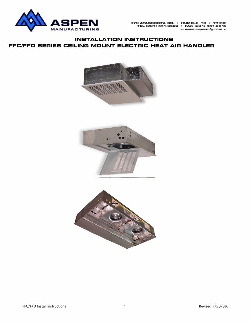
FFC/FFD SERIES CEILING MOUNT ELECTRIC HEAT AIR HANDLERINSTALLATION INSTRUCTIONS
FFC/FFD Install Instructions 1 Revised 7/20/06.
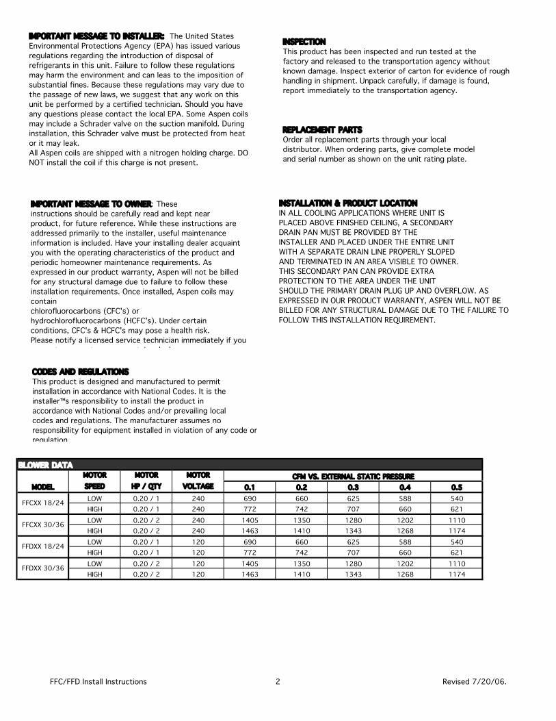
MOTOR MOTOR MOTORSPEED HP / QTY VOLTAGE 0.1 0.2 0.3 0.4 0.5LOW 0.20 / 1 240 690 660 625 588 540HIGH 0.20 / 1 240 772 742 707 660 621LOW 0.20 / 2 240 1405 1350 1280 1202 1110HIGH 0.20 / 2 240 1463 1410 1343 1268 1174LOW 0.20 / 1 120 690 660 625 588 540HIGH 0.20 / 1 120 772 742 707 660 621LOW 0.20 / 2 120 1405 1350 1280 1202 1110HIGH 0.20 / 2 120 1463 1410 1343 1268 1174
FFDXX 18/24
FFDXX 30/36
BLOWER DATA
MODELCFM VS. EXTERNAL STATIC PRESSURE
FFCXX 18/24
FFCXX 30/36
IMPORTANT MESSAGE TO INSTALLER: The United States Environmental Protections Agency (EPA) has issued various regulations regarding the introduction of disposal of refrigerants in this unit. Failure to follow these regulations may harm the environment and can leas to the imposition of substantial fines. Because these regulations may vary due to the passage of new laws, we suggest that any work on this unit be performed by a certified technician. Should you have any questions please contact the local EPA. Some Aspen coils may include a Schrader valve on the suction manifold. During installation, this Schrader valve must be protected from heat or it may leak.All Aspen coils are shipped with a nitrogen holding charge. DO NOT install the coil if this charge is not present.
IMPORTANT MESSAGE TO OWNER: Theseinstructions should be carefully read and kept nearproduct, for future reference. While these instructions are addressed primarily to the installer, useful maintenance information is included. Have your installing dealer acquaint you with the operating characteristics of the product and periodic homeowner maintenance requirements. As expressed in our product warranty, Aspen will not be billed for any structural damage due to failure to follow these installation requirements. Once installed, Aspen coils may containchlorofluorocarbons (CFC's) orhydrochlorofluorocarbons (HCFC's). Under certainconditions, CFC's & HCFC's may pose a health risk.Please notify a licensed service technician immediately if you suspect your system may contain a leak.
REPLACEMENT PARTSOrder all replacement parts through your localdistributor. When ordering parts, give complete modeland serial number as shown on the unit rating plate.
INSTALLATION & PRODUCT LOCATIONIN ALL COOLING APPLICATIONS WHERE UNIT ISPLACED ABOVE FINISHED CEILING, A SECONDARYDRAIN PAN MUST BE PROVIDED BY THEINSTALLER AND PLACED UNDER THE ENTIRE UNITWITH A SEPARATE DRAIN LINE PROPERLY SLOPEDAND TERMINATED IN AN AREA VISIBLE TO OWNER.THIS SECONDARY PAN CAN PROVIDE EXTRAPROTECTION TO THE AREA UNDER THE UNITSHOULD THE PRIMARY DRAIN PLUG UP AND OVERFLOW. AS EXPRESSED IN OUR PRODUCT WARRANTY, ASPEN WILL NOT BE BILLED FOR ANY STRUCTURAL DAMAGE DUE TO THE FAILURE TO FOLLOW THIS INSTALLATION REQUIREMENT.
INSPECTIONThis product has been inspected and run tested at thefactory and released to the transportation agency without known damage. Inspect exterior of carton for evidence of rough handling in shipment. Unpack carefully, if damage is found, report immediately to the transportation agency.
CODES AND REGULATIONSThis product is designed and manufactured to permitinstallation in accordance with National Codes. It is theinstaller™s responsibility to install the product inaccordance with National Codes and/or prevailing localcodes and regulations. The manufacturer assumes noresponsibility for equipment installed in violation of any code or regulation.
FFC/FFD Install Instructions 2 Revised 7/20/06.
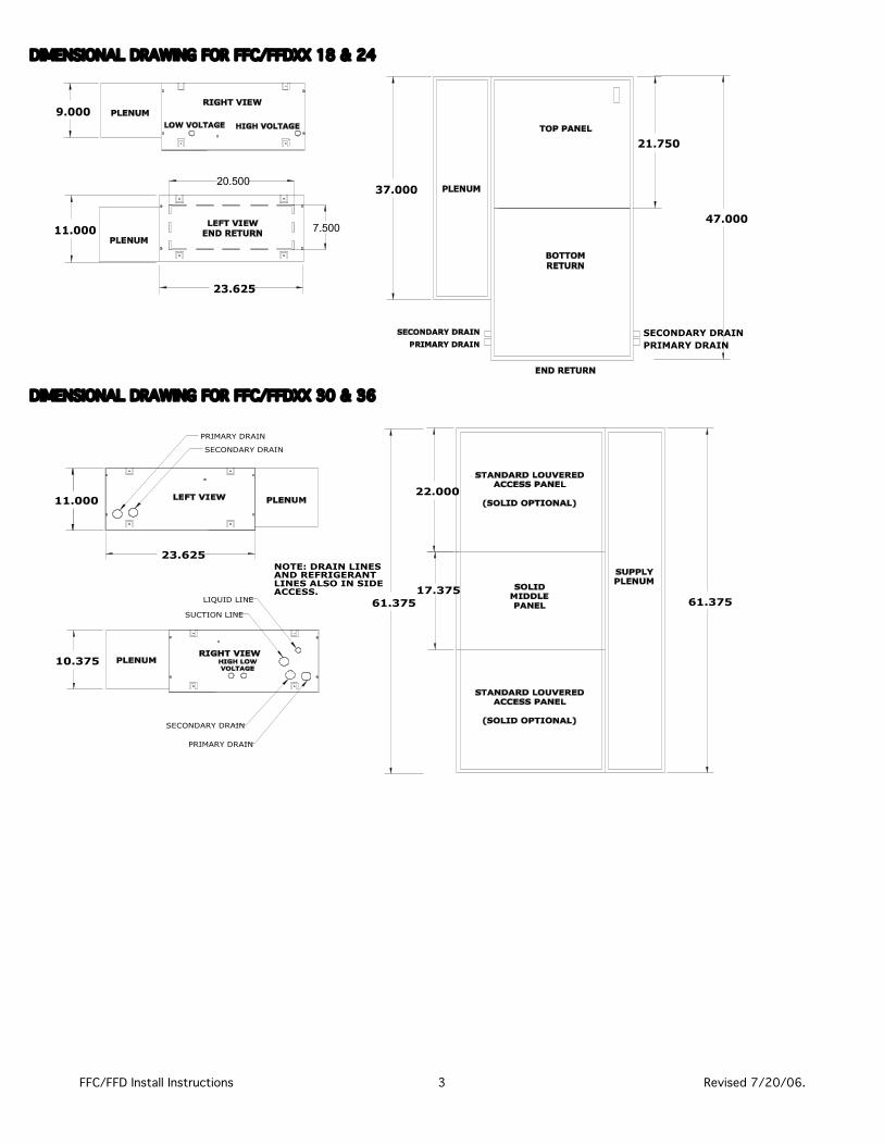
DIMENSIONAL DRAWING FOR FFC/FFDXX 18 & 24
DIMENSIONAL DRAWING FOR FFC/FFDXX 30 & 36
9.000
47.000
37.000
21.750
11.000
23.625
20.500
7.500
SECONDARY DRAINPRIMARY DRAIN
11.000
23.625
10.375
61.37561.375
22.000
17.375
SECONDARY DRAIN
PRIMARY DRAIN
SUCTION LINE
LIQUID LINE
SECONDARY DRAIN
PRIMARY DRAIN
NOTE: DRAIN LINESAND REFRIGERANTLINES ALSO IN SIDEACCESS.
FFC/FFD Install Instructions 3 Revised 7/20/06.
OPERATION SERVICE0'' 0''
FRONT 0'' 0''
SIDES 0'' 0''
REAR 0'' 0''
INSTALLATION CLEARANCES
TOP
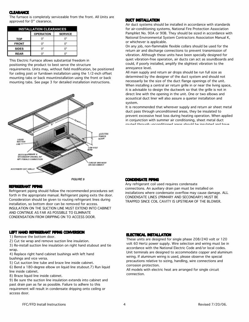
CLEARANCEThe furnace is completely serviceable from the front. All Units are approved for 0'' clearance.
This Electric Furnace allows substantial freedom inpositioning the product to best serve the structurerequirements. Units may, without field modification, be positioned for ceiling joist or furrdown installation using the 1/2-inch offset mounting tabs or back mountinstallation using the front or back mounting tabs. See page 3 for detailed installation instructions.
REFRIGERANT PIPINGRefrigerant piping should follow the recommended procedures set forth in the appropriate manual. Refrigerant piping exits the door. Consideration should be given to routing refrigerant lines during installation, so bottom door can be removed for access. INSULATION ON THE SUCTION LINE MUST EXTEND INTO CABINET AND CONTINUE AS FAR AS POSSIBLE TO ELIMINATE CONDENSATION FROM DRIPPING ON TO ACCESS DOOR.
DUCT INSTALLATIONAir duct systems should be installed in accordance with standards for air-conditioning systems, National Fire Protection Association Pamphlet No. 90A or 90B. They should be sized in accordance with National Environmental System Contractors Association Manual K, or whichever is applicable. On any job, non-flammable flexible collars should be used for the return air and discharge connections to prevent transmission of vibration. Although these units have been specially designed for quiet vibration-free operation, air ducts can act as soundboards and could, if poorly installed, amplify the slightest vibration to the annoyance level. All main supply and return air drops should be run full size as determined by the designer of the duct system and should not necessarily be the size of the duct flange openings of the unit.When installing a central air return grille in or near the living space, it is advisable to design the ductwork so that the grille is not in direct line with the opening in the unit. One or two elbows and acoustical duct liner will also assure a quieter installation and system. It is recommended that wherever supply and return air sheet metal duct pass through unconditioned areas, they be insulated to prevent excessive heat loss during heating operation. When applied in conjunction with summer air conditioning, sheet metal duct routed through unconditioned areas should be insulated and have
LEFT HAND REFRIGERANT PIPING CONVERSION1) Remove the bottom door.2) Cut tie wrap and remove suction line insulation.3) Re-install suction line insulation on right hand stubout and tie wrap.4) Replace right hand cabinet bushings with left handbushings and vice versa.5) Cut suction line tube and braze line inside cabinet.6) Bend a 180-degree elbow on liquid line stubout.7) Run liquid line inside cabinet.8) Braze liquid line inside cabinet.9) Be sure the suction line insulation extends into cabinet and past drain pan as far as possible. Failure to adhere to this requirement will result in condensate dripping onto ceiling or access door.
CONDENSATE PIPINGAny refrigerant coil used requires condensateconnections. An auxiliary drain pan must be installed on installations where condensate overflow may cause damage. ALL CONDENSATE LINES (PRIMARY AND SECONDARY) MUST BE TRAPPED SINCE COIL CAVITY IS UPSTREAM OF THE BLOWER.
ELECTRICAL INSTALLATIONThese units are designed for single phase 208/240 volt or 120 volt 60 Hertz power supply. Wire selection and wiring must be in accordance with the National Electric Code and/or local codes. Unit terminals are designed to accommodate copper and aluminum wiring. If aluminum wiring is used, please observe the special precautions relative to sizing, handling, wire connections and corrosion protection.All models with electric heat are arranged for single circuit connection.
FFC/FFD Install Instructions 4 Revised 7/20/06.
FFC/FFD Install Instructions 5 Revised 7/20/06.
CFM = OUTPUT (BTUH)1.08 X TEMP RISE
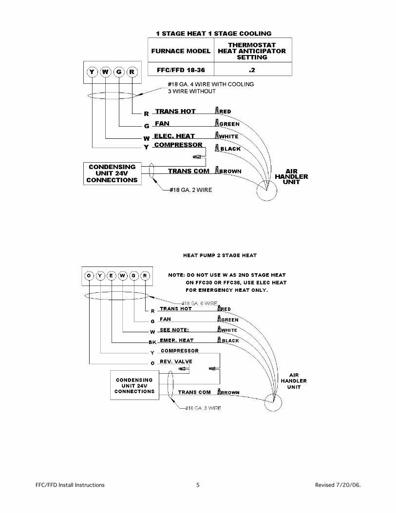
START UPAfter all connections are made, start up and check out of the unit must be performed before proper evaluation of the entire system can be made. Make sure that heat anticipator is properly set as noted on low voltage wiring diagrams.Load requirements can vary in each residence and itmay be necessary for the installer or homeowner tomake slight adjustments to the heat anticipator setting for longer or shorter cycles. It is recommended to change the setting no more than plus or minus .05 amp. at one time. Greater changes can cause the unit to rapid cycle or remain on excessively. To properly check the unit's operation, the installer should have an electrical current measuring device (0-10 amp Amprobe), airpressure measuring device (0-1.0 in slope gauge), and a temperature-measuring device (0-200ºF thermometer). Install the amprobe to measure blower current, the slope gauge to measure static air pressure at the units and the temperature device to measure unit supply and return air temperature. Before taking measurements, be sure thatall registers, grilles and dampers are open or are set to their proper positions. Be sure that clean filters are in place. Temperature measuring device must be installed to obtain average temperature at both inlet and outlet. For outlet, measure temperature of each main trunk at a location far enough away to avoid heater radiation and read the average temperatures.
ELECTRIC FURNACE1. Turn on power supply. Set thermostat fan switch to on. Set cooling indicator to maximum, heating tominimum. System switch may be on heat or cool. Check slope gauge measurement against appropriate air flow chart. Make damper, register and motor speed adjustments to obtain required airflow.2. Set thermostat fan switch to auto, system to heat andthermostat heating indicator to maximum heat. Blower should start and all heat be energized.3. Check air flow using temperature rise method.
NOTE: BTUH output should be computed by VOLT xAMPS x 3.4 = BTUH OUTPUT. Since line volt can vary, do not use nameplate rating to determine output.
OPERATION AND MAINTENANCE1) Room Thermostat- This is the device that controls that operation of your heating and/or cooling unit. It senses the indoor temperature and signals the equipment to start or stop maintaining the temperature you have selected for your comfort. The room thermostat should be in a central, draft free inside wall location for best operation. Do not place any heat producing apparatus such as lights, radio, etc., near the thermostat as this will cause erratic operation of the comfort system.The thermostat can accumulate dust or lint, which can affect its accuracy. It should be cleaned annually.2) Air Filter(s)- All central air moving comfort systems must include air filter(s). These filters will be located either in the equipment or in the return air duct system upstream of the equipment. The filter(s) removes dust and debris from the air thus helping to keep your air-conditioned space clean. More important, the filter keeps dust and debris from collecting on the heat transfer surfaces thus maintaining optimum equipment efficiency and performance. Inspect and clean or replace filters every month. This routine maintenance procedure willpay big dividends in reduced operating cost and reduced service expense. Never operate comfort equipment without filter(s).3) Fuses and/or Circuit Breakers- This comfortequipment should be connected to the building electric service in accordance with local and National Electric codes. This electrical connection will include over current protection in the form of circuit breakers. Have yourcontractor identify the circuits and the location of over current protection so that you may be in a position to make inspections or replacements in the event the equipment fails to operate.4) WARNINGA) Do not store combustible materials or use gasoline or other flammable liquids or vapors in the vicinity of this appliance.B) Do not operate the comfort equipment with panels removed.C) Have your contractor point out and identify the various cut-off devices, switches, etc., that serve yourcomfort equipment. There is a main switch that will cut off energy to your heating system. Know where they are so that you may cut off the flow of energy in the event ofoverheating.5) Periodic Checkup and Service- This product is designed to provide many years of dependable, trouble-free comfort when properly maintained. Proper maintenance will consist of annual check-ups and cleaning of the internal electrical and heat transfer components by a qualified service technician. Failure to provide periodic checkup and cleaning can result inexcessive operating cost and/or equipment malfunction.6) Lubrication- Direct drive blower motors are equipped with permanently lubricated bearings and do not require further lubrication.
FFC/FFD Install Instructions 6 Revised 7/20/06.


