OLYMPUS RESEARCH MICROSCOPES
INSTRUCTION MANUAL
MODELS FHT&EHTWITH§W:

INSTRUCTION MANUAL
OLYMPUS RESEARCH MICROSCOPES
MODELS
FHT&EHT:~~:~~
TABLE OF CONTENTS
I. STANDARD EQUIPMENT " 2II. SPECiFiCATiONS 4Ill. IDENTIFICATION OF VARIOUS COMPONENTS 5IV. DESCRIPTION OF EACH COMPONENT 6V. OPERATING THE MICROSCOPE 14VI. OPTICAL CHARACTERiSTICS ...............•...... ·19

ISTANDARD EQUIPMENT
Before assembly, please check your standard outfit, which consists ofthe following items:
1. Model FHT, ) Binocular Tube Versions
Con- TotalModel No. Eyepieces Objectives Stage denser magni-
fication
Bi P7x, Bi WF lOx, Ach 4x,Ach lOx, N.A. 28x-FHT-521 Bi P15x, paired Ach 40x. 1.25 1500xAch l00x (oill
Bi P7x, Bi High-Eye- Ach 4x.Ach lOx, FrS N.A. 28x-FHT-522 pointWF 10x,Bi P15x, FI 40x, FI 100x ISquare 1.40 2000xBi K20x. paired loill mechani·
Bi P7x, Bi High-Eye- Plan 4x. Plan lOx, cal stagewith left N.A. 28x-FHT-523 pointWF lOx. BiP15x. Plan 40x, & right 1.40 2000xBi K20x, paired Plan loox loill handcoaxial N.A.
Plan4x, Plan lOx. controls) 0.85FHT-523- Bi SW10x, paired Plan 20x, Plan40x with 40x-SW SW Plan looxloill aux. con l000x
denserlens
2} Trinocular Tube Versions
Con- TotalModel No. Eyepieces Objectives Stage denser magni-
fication
Bi P7x, BiWF10x,Bi P15x. paired Ach 4x, Ach lOx, N.A. 28x-FHT-531 Photo eyepieces: Ach 40x, 1.25 1500xFK2.5x, FK3.3x Ach 100x (oillFK5x,FK6.7x, leach
Bi P7x, Bi High-Eye- FrSpoint WF10x, Bi P15x, Ach4x,Ach lOx, (Square
FHT-532 Bi K20x, paired FI40x,Fll00x mechani- N.A. 28x-Photo eyepieces: loill cal stage 1.40 2000xFK2.5x, FK3.3x. with leftFK5x,FK6.7x,l each & right
Bi P7x, Bi High-Eye- handcoaxialpoint WF lOx, Bi P15x, Plan4x, Plan lOx. controls)
FHT-533 Bi K20x. paired Plan 40x, N.A. 28x-Photo eyepieces: Plan l00x loill 1.40 2000xFK2.5x, FK3.3x,FK5x,FK6.7x,l each
N.A.SW10x paired Plan4x,Planl0x, 0.85
FHT-533- Photo eyepieces: Plan 20x. Plan40x, with 40x-SW FK2.5x, FK3.3x, SWPlan looxloill aux. con· looox
FK5x,FK6.7x,l each denserlens.
Other items supplied with each version:Spare Bulbs,6V.5A, TB-' _ . _ . .. 2pcs.F ilter(blue) . . . . . . . . . . . . . . . . . . . . . . . .. , pc.Filter Mount (provided only with achromatic/aplanatic condenser) 1pc.Wooden Carrying Case. . 1pc.Certificate . . . . . 1pc.
2
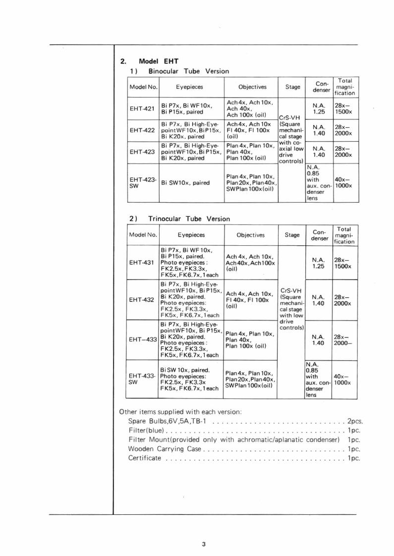
2. Model EHT, ) Binocular Tube Version
Can·Total
Model No. Eyepieces Objectives Stage denser magni-fication
Bi P7x, Bi WF10x.Ach4x, Ach lOx.
N.A. 28x-EHT-421 Ach 40x.8i P15x, paired Ach loox (oill 1.25 1500xCrS·VH
Bi P7x, BI High·Eye· Ach4x. Ach lOx ISquare N.A. 28x-EHT-422 pointWFl Ox. Bi Pl 5x. FI 40x. FI loox mechani-
1.40 2000xBi K20x. paired loill cal stage
Bi P7x, Bi High·Eye- Plan 4x. Plan lOx. with co-axial low N.A. 28x-
EHT-423 pointWF 1Ox.Bi Pl 5x. Plan 40x. drive 1.40 2000xBi K20x. paired Plan loox loill controls)
N.A.
Plan 4x. Plan lOx. 0.85EHT-423· with 40x-SW
Bi SW10x. paired Plan20x. Plan40x, aux. con· loooxSWPlan looxloill denser
lens
2) Trinocular Tube Version
Con- TotalModel No. Eyepieces Objectives Stage denser magni·
fication
Bi P7x. Bi WF lOx,Bi P15x. paired. Ach 4x. Ach lOx, N.A. 28x-EHT-431 Photo eyepieces : Ach40x,Achloox 1.25 1500xFK2.5x, FK3.3x, (oillFK5x,FK6.7x,1 each
Bi P7x. Bi High·Eye-pointWF10x, Bi P15x,
Ach4x,Ach lOx, CrS·VH
EHT-432 Bi K20x, paired.FI 40x. FI loox (Square N.A. 28x-
Photo eyepieces:(oill
mechani- 1.40 2000xFK2.5x, FK3.3x, cal stageFK5x, FK6.7x, 1each with low
Bi P7x, Bi High·Eye- drivecontrols)pointWF10x, Bi Pl 5x, Plan 4x, Plan lOx,
EHT-433 Bi K20x, paired. Plan 40x, N.A. 28x-Photo eyepieces : Plan loox (oil) 1.40 2000-FK2.5x, FK3.3x,FK5x, FK6.7x,l each
N.A.Bi SW lOx, paired.
Plan4x, Plan lOx, 0.85EHT·433· Photo eyepieces:
Plan 20x ,Plan40x, with 40x-SW FK2.5x, FK3.3x SWPlan lOOx(oill aux. con- 1000x
FK5x, FK6.7x,l each denserlens
Other items supplied with each version:Spare Bulbs,6V,5A.TB·' 2pcs.Filler(blue) . . . . . . . . . . . . . . . . . . . . . . . . . . . . . . . . . . . . .. , pc.Filter Mount(provided only wilh achromatic/aplanalic condenser) 1pc.Wooden Carrying Case. 1pc.Certificate . . . . . . . . 1pc.
3
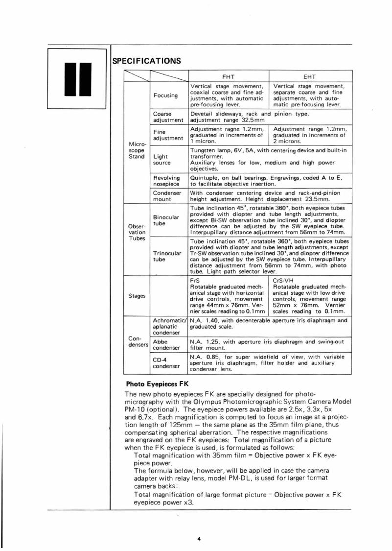
IISPECIFICATIONS
~ --------FHT EHT
Vertical stage movement. Vertical stage movement.
Focusing coax ial coarse and fine ad· separate coarse and finejustments, with automatic adjustments. with auto-pre·focusing lever. matic pre-focusing lever.
Coarse Devetait slideways, rack and pinion type:adjustment adjustment range 32.5 mm
Fine Adjustment ragne 1.2mm. Adjustment range 1.2mm,
adjustment graduated in increments of graduated in increments of
Micra- 1 micron. 2 microns.
scope Tungsten lamp, 6V. 5A, with centering device and built·inStand Light transformer.
source Auxiliary lenses for low, medium and high powerobjectives.
Revolving Quintuple, on ball bearings. Engravings. coded A to E.nosepiece to facilitate objective insertion.
Condenser With condenser centering device and rack·and-pinionmount height adjustment. Height displacement 23.5mm.
Tube inclination 45-, rotatable 360-, both eyepiece tubes
Binocularprovided with diopter and tube length adjustments,
tube except Bi-SW observation tube inclined 30-, and diopterObser- difference can be adjusted by the SW eyepiece tube.vation Interpupillary distance adjustment from 56mm to 74mm.Tubes Tube inclination 45·, rotatable 360·, both eyepiece tubes
provided with diopter and tube length adjustments, exceptTrinocular Tr-SWobservation tube inclined 30·, and diopter differencetube can be adjusted by the SW eyepiece tube. Interpupillary
distance adjustment from 56mm to 74mm, with phototube. Light path selector lever.
FrS CrS·VHRotatable graduated mech· Rotatable graduated mech·
Stages anical stage with horizontal anical stage with low drivedrive controls, movement controls, movement rangerange 44mm x 76mm. Ver· 52mm x 76mm. Verniernier scales reading to O. 1mm scales reading to 0.1mm.
Achromatic! NA 1.40, with decenterable aperture iris diaphragm andaplanatic graduated scale.condenser
Can· Abbe N.A. 1.25, with aperture iris diaphragm and swing-outdenserscondenser filter mount.
CO-4 N.A. 0.85, for super widefield of view, with variable
condenseraperture iris diaphragm, filter holder and auxiliarycondenser lens.
Photo Eyepieces F K
The new photo eyepieces F K are specially designed for photomicrography with the Olympus Photomicrographic System Camera ModelPM-10 (optional). The eyepiece powers available are 2.5x, 3.3x, 5xand 6.7x. Each magnification is computed to focus an image at a projection length of 125mm - the same plane as the 35mm film plane, thuscompensating spherical aberration. The respective magnificationsare engraved on the FK eyepieces: Total magnification of a picturewhen the F K eyepiece is used. is formulated as follows:
Total magnification with 35mm film = Objective power x FK eyepiece power.The formula below, however. will be applied in case the camp.raadapter with relay lens, model PM-D L, is used for larger formatcamera backs:Total magnification of.large format picture = Objective power x FKeyepiece power x3.
4

IIIIDENTIFICATION OF VARIOUS COMPONENTS
Trinocular Observation Tube
Limb
VoltageAdjustmentKnob
FHT·533
5
Eyepiece
RevolvingNosepiece
Objective
5'"",
Conden~r
Voltmeter

IVDESCRIPTION OF EACH COMPONENT
A. Mic:roMlOpe Sund1. Limb 8nd Focusi"9 Mech..,ism
The limb is securely attached to the sturdy base and supports the observation tube, stage, condenser, revolving nosepiece and focusing mechanism.
The focusing mechanism includes the coarse and fine adjustments and anautomatic pre-focusing lever. This lever is provided to prevent possiblecontact between specimen and objective as well as to simplify coarsefocusing. The lever is locked after coarse focus has been accomplished.This prevents further upward travel of the stage and automatically provides a limiting stop if the stage is lowered then raised again. Theautomatic pre-focusing lever does not restrict fine focusing.The filter mount is plaoed on the light exit of the illuminator base.
Stage Clamping Lever
Co_Adjustment Knob
FineAdjustment Knob
AutomaticPre-focusing Lever
FHT
Aux iI iory LensShifting Lever
Fillllr Mount
Light Exit
CoaneAdjustment Knob
FineAdjustment Knob
2. CondenserThe condenser may be mounted on the condenser mount by firstinserting the condenser into the condenser mount from below, aligningthe positioning dots on the condenser and condenser mount, and thenclamping with the clamping screw. Condenser centration can beaccomplished by means of two centering knobs. Vertical movement ofthe condenser can be adjusted by the condenser height adjustment knob.The condenser has an excellent resolving power, dry or oil immersion,from 4x to 100x magnification objectives. When using the 100xobjective, the distance between condenser and specimen should befilled with immersion oil.Note: For use with the achromaticlaplanatic condenser N.A. 1.40, thefilter mount is placed on the light exit of the illuminator base, whileeither the Abbe N.A. 1.25 or N.A. 0.85 condenser incorporates itsown filter mount. When the N.A. 0.85 condenser is used for superwidefield observation, keep the auxiliary condenser lens slipped on thelight ex it on the base.The slide clamping screw permits simultaneous locking of slide and
6

rotation of condenser and the slide lever allows decentering and rotatingthe aperture iris diaphragm for obligue illumination.
• Abbe Conden5el", N.A. 1.25
Abbe COI"denser --------
Condenser ClampingScrew
Centering Knob
Filter Moun't-~--'
• Achromatic/aplanatic Condenser, N.A. 1.4
AchromaticlaplanaticCondenser ------CondenserClamping
Screw----~-.
Centering KnobAperture IrisDiaphragmCuntrol Aing-~-r-'
• CD-4 Condenser, N.A. 0.85
Condenser
Condenser Mount
Aperture Irisl..::>..._---- Diaphragm
Control lever
,,~~- Alignment Dots
/ Condenser Mount
Slide ClampingScrew
~...... Alignment Dots
----Slide Lever
Condenser MOllnt
Condenser ClampingScrew
Centering Knob
Filter Mount
Alignment Dots
Aperture IrisDiaphragm ControlLeve<
7
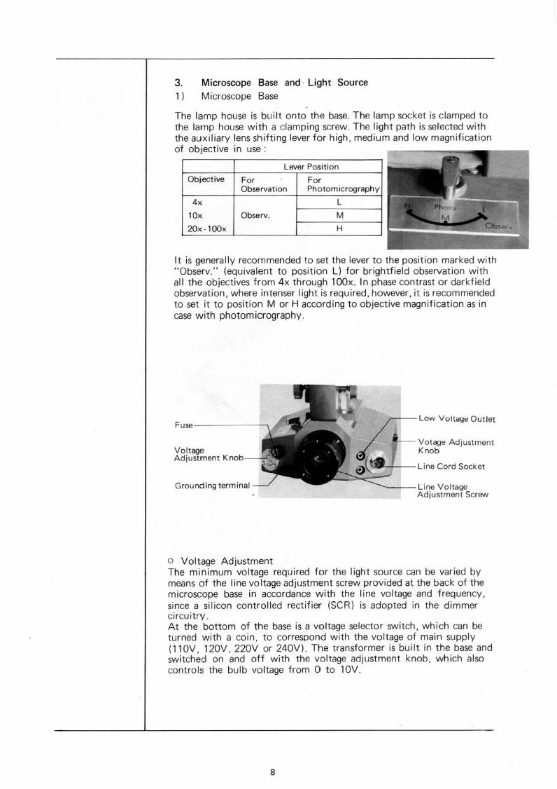
Lever Position
H
L
Fo,Photomicrography
4x
lOx Observ.
20x-l00x
Objective ForObservation
3. Microscope Base and· Light Source1) Microscope Base
The lamp house is built onto the base. The lamp socket is clamped tothe lamp house with a damping screw. The tight path is selected withthe auxiliary lens shifting lever for high, medium and low magnificationof objective in use. ...__..
It is generally recommended to set the lever to the position marked with"Observ." (equivalent to position L) for brightfield observation withall the objectives from 4x through 100x. In phase contrast or darkfieldobservation, where in tenser light is required, however, it is recommendedto set it to position M or H according to objective magnification as incase with photomicrography.
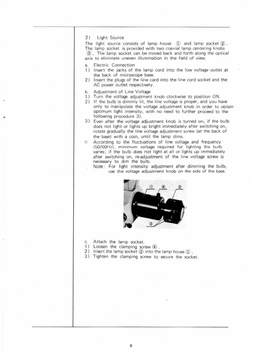
VoltageAdjustment Knob
Grounding terminal ..::::::;::;",::::~--Line VoltageAdjustment Screw
o Voltage AdjustmentThe minimum voltage required for the light source can be varied qvmeans of the line voltage adjustment screw provided at the back of themicroscope base in accordance with the line voltage and frequency,since a silicon controlled rectifier (SeRl is .adopted in the dimmercircuitry.At the bottom of the base is a voltage selector switch, which can beturned with a coin, to correspond with the voltage of main supply(11 OV, 120V, 220V or 240Vl. The transformer is built in the base andswitched on and off with the voltage adjustment knob, which alsocontrols the bulb voltage from 0 to lOV.
8
•
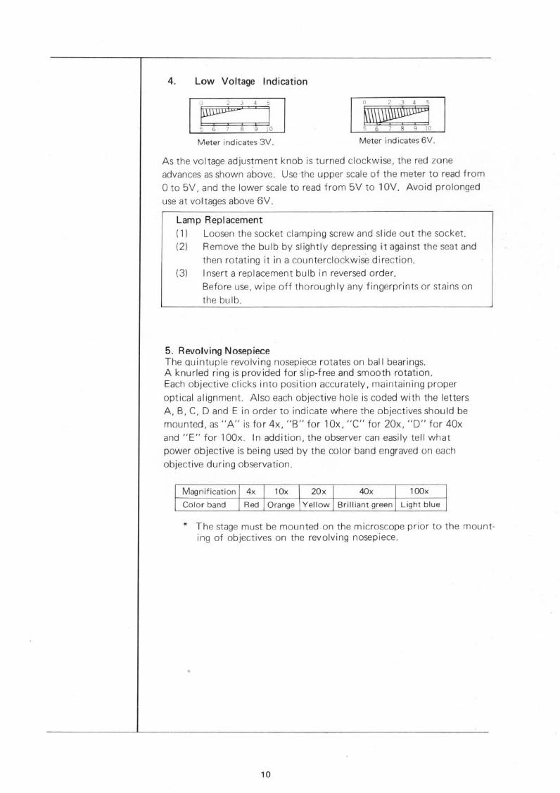
2 ) Light SourceThe light source consists of lamp house CD and lamp socket ® .The lamp socket is provided with two coaxial lamp centering knobs@ _ The Jamp socket can be moved back and forth along the optical
axis to eliminate uneven illumination in the field of view.
a. Electric Connection1) Insert the jacks of the lamp cord into the low voltage outlet at
the back of microscope base.2) Insert the plugs of the line cord into the tine cord socket and the
AC po......er outlet respectively.
b. Adjustment of Line Voltage1) Turn the voltage adjustment knob clockwise to position ON.2) If the bulb is dimmly lit. the line voltage is proper, and you have
only to manipulate the voltage adjustment knob in order to obtainoptimum light intensity. with no need to further proceed to thefollowing procedure 3).
3) Even after the voltage adjustment knob is turned on, if the bulbdoes not light or lights up bright immediately after switching on,rotate gradually the line voltage adjustment screw (at the back ofthe base) with a coin, until the lamp dims.
o According to the fluctuations of line voltage and frequency(SO/60Hz), minimum voltage required for lighting the bulbvaries; if the bulb does not light at all or lights up immediatelyafter switching on, re-adjustment of the line voltage screw isnecessary to dim the bulb.Note: For light intensity adjustment after dimming the bulb,
use the voltage adjustment knob on the side of the base.
c. Attach the tamp socket.1) Loosen the clamping screw <!) .2) Insert the lamp socket @ into the lamp house CD .3) Tighten the clamping screw to secure the socket.
9
4. Low Voltage Indication
~' ~ 15 ;; 1 8 9 10
Meter indicates 3V. Meter indicates 6V,
As the voltage adjus~ment knob is turned clockwise, the red zoneadvances as shown above. Use·the upper scale of the meter to read fromo to 5V, and the lower scale to read from 5V to lOV. Avoid prolonged
use at voltages above 6V.
Lamp Replacementl 1) Loosen the socket clamping screw and slide out the socket.l2l Remove the bulb by slightly depressing it against the seat and
then rotating it in a counterclockwise direction.(3l Insert a replacement bulb in reversed order.
Before use, wipe off thoroughly any fingerprints or stains onthe bulb.
5. Revolving NosepieceThe Quintuple revolving nosepiece rotates on ball bearings.A knurled ring is provided for slip-free and smooth rotation.Each objective clicks Into position accurately, maintaining properoptical alignment. Also each objective hole is coded with the lettersA, 8, C, D and E in order to indicate where the objectives should bemounted, as "A" is for 4x, "B" for lOx, "C" for 20x, "0" for 40xand "E" for 100x In addition, the observer can easily tell whatpower objective is being used by the color band engraved un eachobjective during observation.
Magnification 4x 10, 20, HlQ,
Color band Red Orange Yellow Brilliant green Light blue
* The stage must be mounted on the microscope prior to the mounting of objectives on the revolving nosepiece.
'0
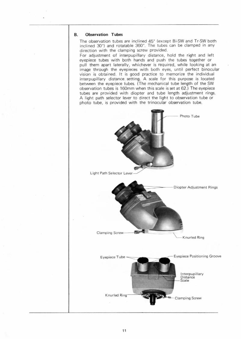
B. Observation Tubes
The observation tubes are inclined 45" (except Bi·SW and Tr-SW bothinclined 30°) and rotatable 360°. The tubes can be clamped in anydirection with the clamping screw provided.For adjustment of interpupillary distance. hold the right and lefteyepiece tubes with both hands and push the tubes together orpull them apart laterally, whichever is required, while looking at animage through the eyepieces with both eyes, until perfect binocularvision is obtained. It is good practice to memorize the individualinterpupillary distance. setting. A scale for this purpose is locatedbetween the eyepiece tubes. (The mechanical tube length of the SWobservation tubes is 160mm when this scale is set at 62.l The eyepiecetubes are provided with diopter and tube length adjustment rings.A light path selector lever to direct the light to observation tube orphoto tube, is provided with the trinocular observation tube.
Photo Tube
Light Path Selector lever
;:::===--- Diopter Adjustment Rings
Clamping Screw---tllIO'lt__
Eyepiece Tube
Knurled Ring,--"'-\
11
~Knurled Ring
-r- Eyepiece Positioning Groove
InterpupillaryDistanceScale
Clamping Screw

Clamping Screw -~~~~~~-.!J!!~~~-
Photo Tube
Ujht PathSe ector Lever
C. Stages
1. Square Mechanical Stage FrSThis is a square coaxial drive control mechanical stage with interchangeable mount. The specimen is moved by means of horizontal drive controlson both sides of the stage. The larger control knob is for north-south (Y)movement of the specimen, and the smaller control knob is for east-west(X) movement.The working range of the specimen holder is:North-south excursion ... 44mmEast-west excursion. . .. . 76mmEach control is provided with a scale (0-50 for Y excursion, 50-120 forX excursion) and a vernier, reading to 0.1 mm. Stage rotation can beclamped by a clamping screw. The stage may be used as a plain stage byremoving the specimen holder assembly.
Graduated Scale forNorth-South Movement
Stage RotationClamping Screw
Graduated Scale forEast-West Movement
------- Specimen Holder
Clampinq Screws forSpeCimen Holder
North-South MovementControl Knob
East-West MovementControl Knob
MovementControl Kno
* The stage may be mounted on the microscope in reversed position, asshown in the picture above, right, to obtain increased rotation.
'2
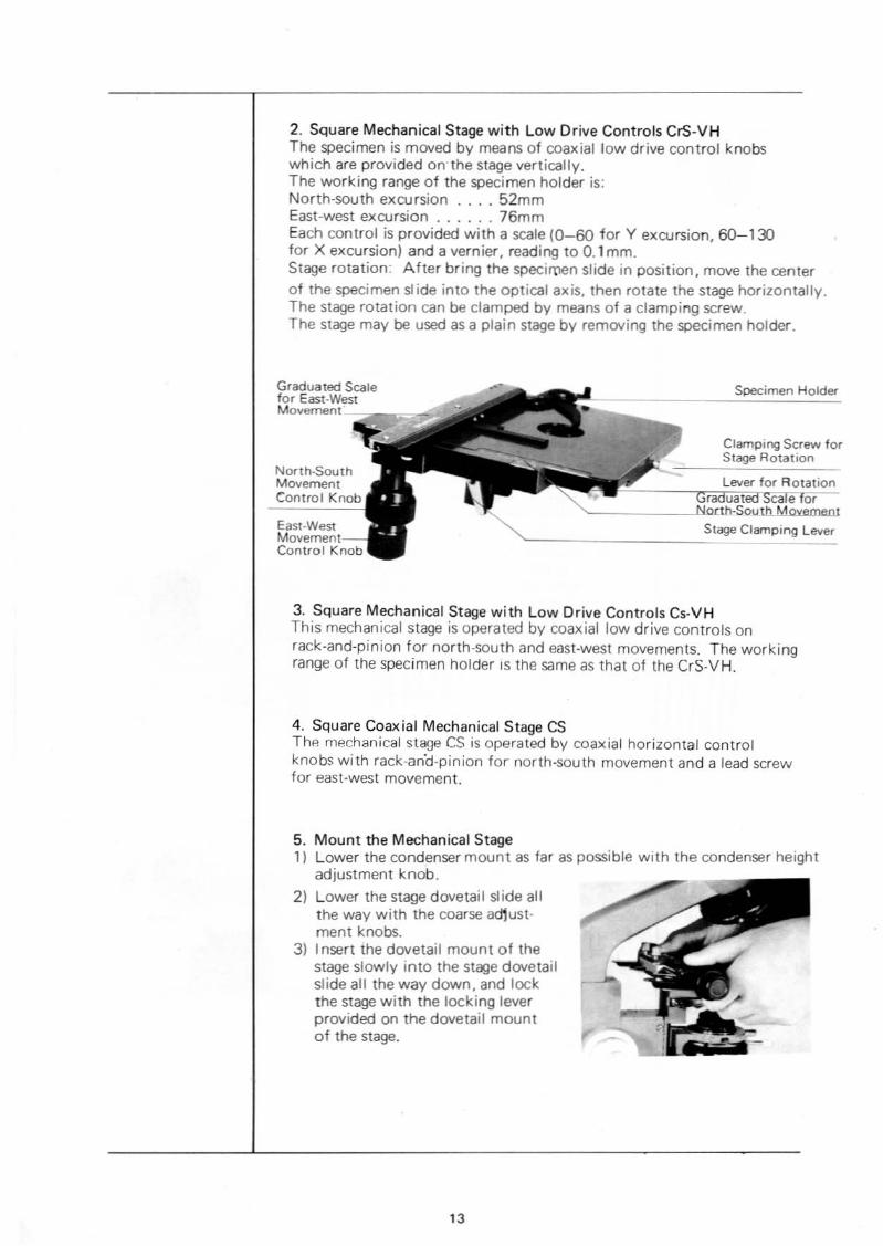
2. Square Mechanical Stage with Low Drive Controls CrS-VHThe specimen is moved by means of coaxial low drive control knobswhich are provided on'the stage vertically.The working range of the specimen holder is:North-south excursion , 52mmEast-west excursion 76mmEach control is provided with a scale 10-60 for Y excursion, 6O~13)for X excursion) and a vernier, reading to 0.1 mm.Stage rotation: After bring the specimen slide in position, move the centerof the specimen slide into the optical axis. then rotate the stage horizontally.The stage rotation can be clamped by means of a clamping screw.The stage may be used as a plain stage by removing the specimen holder.
Graduated Scalefor East-WestMovement __....'"
North.southMovementControl Knob
East-WestMovementControl Knob
Specimen Holdel"
Clamping Screw forStage Rotation
~ ~=~l",:;;e;';f,orRotationr uat Scale for
'-- ~"'onh-SolJthMovemeoJ
Stage Clamping lever
3, Square Mechanical Stage with Low Drive Controls Cs-VHThis mechanical stage is operated by coaxial low drive controls onrack-and-pinion for north-south and east-west movements. The workingrange of the specimen holder IS the same as that of the CrS-VH.
4, Square Coaxial Mechanical Stage CSThp- mechanical stage CS is operated by coaxial horizontal controlknobs with rack-an"d-pinion for north-south movement and a lead screwfor east-west movement.
5. Mount the Mechanical Stage1) Lower the condenser mount as far as possible with the condenser height
adjustment knob.
2) Lower the stage dovetail slide allthe way with the coarse adjustment knobs.
3) Insert the dovetail mount of thestage slowly into the stage dovetailslide all the way down. and lockthe stage with the locking leverprovided on the dovetail mountof the stage.
13

y OPERATING THE MICROSCOPEA. Interpupillary Distance and Diopter Adjustments
In order to obtain perfect binocular vision through the eyepieces, it isnecessary to adjust interpupillary distance and diopter difference in eyeacuity; otherwise, long time observation would put considerable strain onthe obser'.;er's eyes.1. Interpupiltary 0 istance Adjustment(1) Hold the (igh t and lef t eyepiece tubes with both hands and push the
tubes together, or pull them apart laterallY,whichever is required,while looking through the eyepieces with both eyes, until perfectbinocular vision is obtained.
(2) Memorize your interpupillary distance setting. Scale CD is providedfor this purpose, located between the eyepiece tubes.
* This interpupillary distance adjustment is necessary each timeobservers are changed. Re-focusing is also necessary whenever theinterpupillary distance is changed.
2. Diopter Adjustmenta. For FHT and EHT
(1) Rotate the diopter ring ® on the right eyepiece tube to match thescale on the ring to your interpupillary distance setting which youobtained from scale CD as described in the preceding paragraph1-121
(2) Look at the image through theright eyepiece with your righteye and focus on the specimenwith the fine adjustment knobs.
(3) Next, look at the image throughthe left eyepiece with your lefteye and rotate the diopter ring@to focus on the specimen without using the coarse and fineadjustment knobs.
b. For FHT-SW and EHT-SWEach SW eyepiece is provided withdiopter ring for adjustment of yourdiopter difference.(1) Rotate the diopter ring on the
right eyepiece tube to obtaina clear image of the field ofview in the eyepiece.
(2) Look at the image through theright eyepiece with your righteye and focus on the specimenwith the fine adjustment knobs.
(3) Next,look at the image throughthe left eyepiece with your lefteye and rotate the diopter ringto focus on the specimen without using the coarse and fineadjustment knobs.
14

B. Center the Condenser and the Light Bulb
After all necessary components are attached to the microscope standproperly and securely, it is essential to center the condenser and thelight bulb before the microscope is put in operation.1. First, make sure that all electrical conne~tions are done property,
then turn the switch in the microscope base to the ON position.The lamp will light up. By raising the voltage progressively, you canascertain that the bulb is on.Adjust light intensity to suit your requirements.
2. Swing the auxiliary lens shifting lever on the illuminator base to position Observ.
3. Place a specimen on the stage and use the objective lOx to bring thespecimen in focus.
oOut of center.
oCentered. Opened fu lIy.
4. Stop down the field iris diaphragm with the field iris diaphragmcontrol provided on the microscope base. A slightly blurred imageof the field iris diaphragm can now be seen in the field of view.
5. Move the condenser up and down with the condenser heightadjustment knob to focus on the image of the field iris diaphragm.
;(;rvvv,
\"IJU<NUUU/
Before centration. After centration.
6. While widening the diameter of the field progressively, use the condenser centering knobs to bring the diaphragm image into the centerof the field of view. If the polygonal image of the iris diaphragmbecomes inscribed in the field it means that the field iris diaphragm iscentered. Slightly increase the diameter of the field iris diaphragmuntil it is iust outside the field of view.
7. Remove one of the eyepieces from the observation tube, and look intothe eyepiece tube so that the filament image of the bulb at the rearfocal plane of the objective can easily be seen.
8. Center the filament image with the two coaxial centering knobs on thelamp socket.
.. Before re-insertion of the eyepiece into the observation tube, moveyour head to the right or left to ascertain that the filament image is incenter at the rear focal plane of the objective while looking into theeyepiece tube.
I f there is illumination irregularity seen in the field of view after centra.tion of the bulb filament, loosen the clamping screw for positioning the lampsocke~ and move the lamp sod<et back and forth slowly and clamp with theclamping screw when even illumination is obtained.
15

60-10"
,,.,,
C. Use of Iris Diapnragms
A field iris diaphragm as well as an apertureiris diaphragm is provided on the microscope.The field iris diaphragm is built into thebase and the aperture iris diaphragm is partof the condenser.
1. Field Iris DiaphragmThe field iris diaphragm controls the diameter of the ray bundle impinging on thespecimen surface and thus increases imagedefinition. Stop down the field iris diaphragm while looking through the eyepiece.An image of the iris diaphragm will appearwithin the field. Now open the field diaphragm until its diameter is just slightlylarger than the diameter of the field of view.• When particularly clearer definition of
an image is required in the center of thefield of view stop down the iris diaphragm asnarrow as shown in the picture at bottom.
• The image of the field iris diaphragm is conjugated on the specimen'ssurface, so that the diameter of the field iris diaphragm changesaccording to the change of the objective power. By the same tokenwith every change of the eyepiece the field number will be varied,which necessitates re-adjustment of the diameter at the field diaphragm.
2. Aperture Iris DiaphragmAn aperture iris diaphragm opened toowide impairs image con·trast due to internalreflections and related factors. On theother hand, if the diaphragm is stoppeddown exce"->5ivcly, rC50lution is undulyreduced. It is therefore suggested to matchthe opening of the aperture iris diaphragmto the numerical aperture of the objectivein use, in order to achieve maximumobjective performance. For that purposesimply set the numerical aperture scale onthe condenser to the numerical apeflure ofthe objective in use.However, since microscopic specimens generally are low in contrast,their image lacks contrast if the objective is usecl with its full numericalaperture. Therefore. il is occasionally preferable to stop down the apertureiris diaphragm slightly more than indicated by the objective N.A. Thiswill result in increased image contrast, larger depth of focus and a flatterfield. On the other hand, stopping down too much impairs resolution.An aperture setting of O.6-0.7x the N.A. of the objective is recommended.If the N.A. of the objective is 1, for instance, you can set the scale to0.6-0.7.
16
•
•

D. Tension Adjustment of Coarse Adjustment Knobs
While the coarse adjustment motion is normally sliff and heavy, it isfreely adjustable for either heavy or light movemenl depending on theobserver's preference. To adjust the tension hold lhe two coarse adiustmentknobs with your both hands and rolate them in the opposite directionat the same time.
E. ParfocalObjectives
Since alt objectives are par/oeal. only a minimum of fine adJuslment controlis required when you change the objectives.Focusing Procedure:1) Operate the fine adjustment knob to bring the line adjustment indicator
line to the center of the fine adjustment range.2) Place thp. lOx objective in position3) Bring the specimen as closely as possible to the objective with the
coarse adjustment knobs.4) While looking through the eyepiece, lower the stage slowly and focus
on the specimen.5) Turn the revolving nosepiece to bring the objective to be used into
the light path.
F. Use of Immersion Optical Components
1. Immersion Objectives:1) Focus on the specimen with a low-power objective.21 Put a drop of immersion oil on both the specimen and the objective
front lens.3) Turn the revolving nosepiece to bring the immersion objective into
the light path, and focus with the fine adjustment knob.2. Immersion Condensers:1) Remove the specimen from the mechanicul stnge and place a drop of
immersion oil on the front lens of the condenser.2) Place the specimen on the mechanical stage and slowly raise the·con
denser until firm contact with the underside of the specimen slide ismade. Care should be taken to prevent oil bubbles from forming inthe oil film between condenser and specimen slide.
3. After UseCarefully wipe off the immersion oil deposited on the lens surfaces wi thgauze moistened with xylene.Never leave oil on the lens surfaces after use as oil remnants willseriously impair the performance of the lens systems.
17
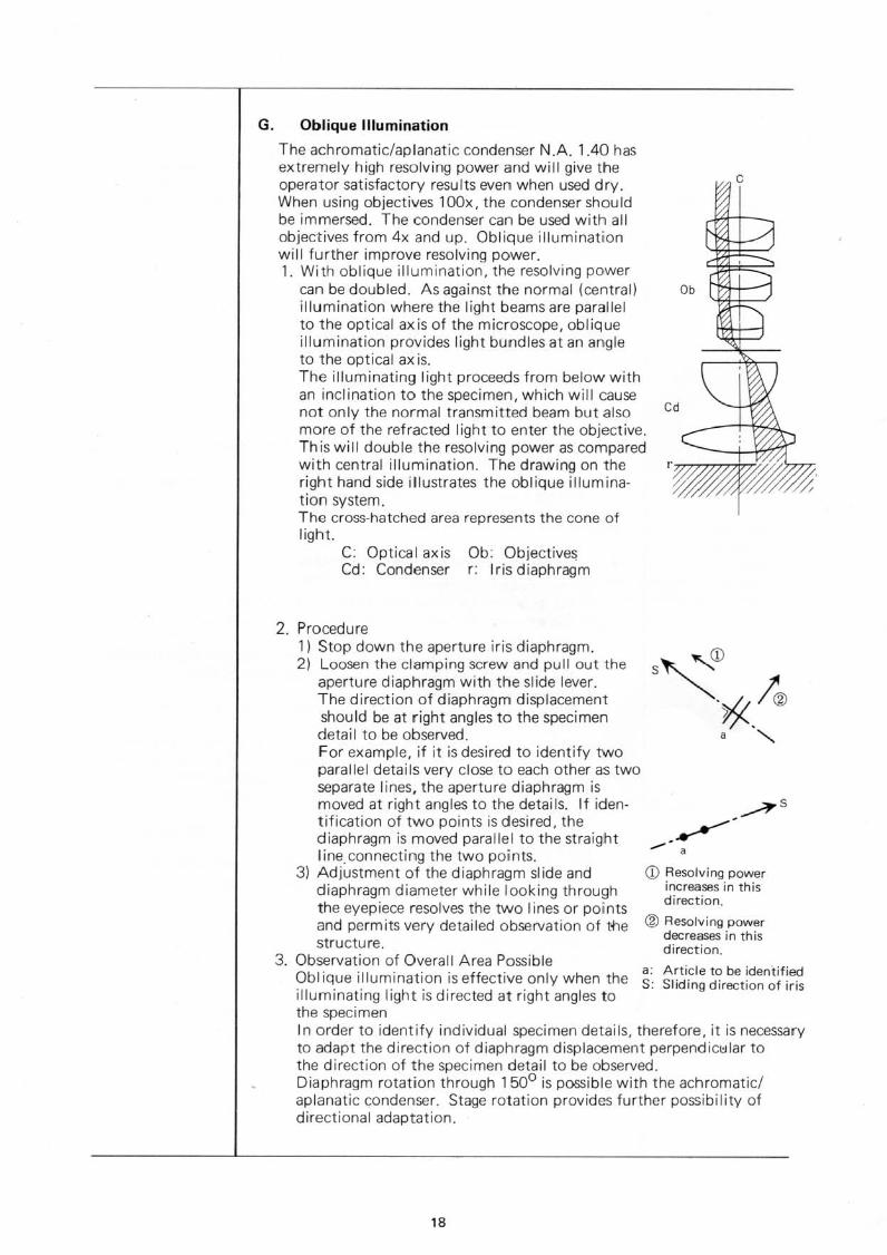
G. Oblique Illumination
The achromatic!aplanatic condenser N.A. 1.40 hasextremely high resolving power and will give theoperator satisfactory results even when used dry.When using objectives lOOx, the condenser shouldbe immersed. The condenser can be used with allobjectives from 4x and up. Oblique illuminationwill further improve resolving power.1. With oblique illumination, the resolving power
can be doubled. As against the normal (central)illumination where the light beams are parallelto the optical axis of the microscope, obliqueillumination provides light bundles at an angleto the optical ax is.The illuminating light proceeds from below withan inclination to the specimen, which will causenot only the normal transmitted beam but alsomore of the refracted light to enter the objective.This will double the resolving power as comparedwith central illumination. The drawing on theright hand side illustrates the oblique illumination system.The cross-hatched area represents the cone oflight.
c
C: Optical axisCd: Condenser
Ob: Objective~
r: Iris diaphragm
CD Resolving powerincreases in thisdirection.
® Resol'Ving powerdecreases in thisdirection.
~s
•
.--------.
2. Procedure1) Stop down the aperture iris diaphragm.2) Loosen the clamping screw and pull out the
aperture diaphragm with the slide lever.The direction of diaphragm displacementshould be at right angles to the specimendetail to be observed.For example, jf it is desired to identify twoparallel details very close to each other as twoseparate Jines, the aperture diaphragm ismoved at right angles to the details. If iden·tification of two points is desired, thediaphragm is moved parallel to the straightline. connecting the two points.
3) Adjustment of the diaphragm slide anddiaphragm diameter while looking throughthe eyepiece resolves the two lines or pointsand permits very detailed observation of tfiestructure.
3. Observation of Overall Area PossibleO a Article to be identified
bl ique illumination is effective only when the S~ Sliding direction of irisilluminating light is directed at right angles tothe specimenIn order to identify individual specimen details, therefore, it is necessaryto adapt the direction of diaphragm displacement perpendicl:llar tothe direction of the specimen detail to be observed.Diaphragm rotation through 1500 is possible with the achromatic!aplanatic condenser. Stage rotation provides further possibility ofdirectional adaptation.
18
H. eare for Storing
Moisture and dust are the most deadly factors to microscopes. Since bothmoisture and dust are found in most laboratories,microscopes shouldbe kept in containers immediately after use. I f this is not possible. theyshould be covered with the vinyl dust cover provided.As for objectives and eyepieces, it is best to keep them in desiccators.Failing this, they should be kept in cases containing such desiccants assilica gel. After.the eyepieces are removed from the microscope. the vacanteyepiece sleeves should be covered with protective caps. By no meansshould a microscope be disassembled for repairs. This should be left tothe Olympus repair service.Microscopes must always be kept clean. F ioe dust on parts that cannotbe reached by hand should be blown or wiped off by means of an airblower or a clean feather.
VIOPTICAL CHARACTERISTICS
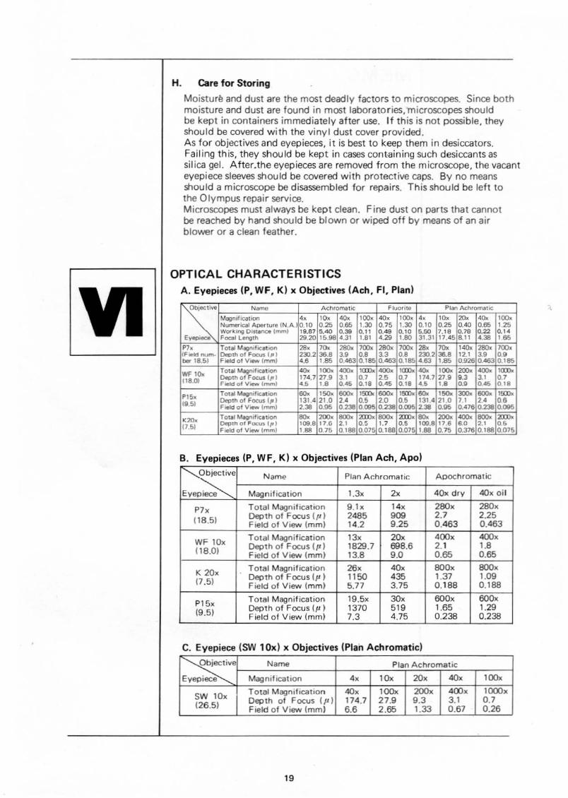
A. Eyepieces (P, WF, K) x Objectives (Ach, FI, Plan)
SN~ Acnromlli( Fluorite Plan AchromatIC
IMgnil'catiOfl 0, '0, 00, ""', '0, '00, 0, ''''' "'" "'" ,."Numerical Aoe.tu.<l IN.A. 0.10 0.25 0.65 0.30 0.75 o.JO 0.10 0.25 0.'0 0.65 0.25WOo'~ing Olst.nao ImmJ 19.81 '.'0 0." 0.11 0.49 0.10 5.50 1.18 0.18 .22 0.14,_Focal LMgth 29.'" 15.98 4.31 1.81 0.29 0.., 31.31 11.45 8.11 ..,8 , 65
P7, Tot" Magn,locltOOft 28, ''''' ""'" """ ""'" ""'",.,.
7"" ,"'" ""'" 700.rFiHl num· Depth 01 Foo;on III I "".7 "'.8 ,.• 0.8 " 0.8 7JO.7 "-8 ", " 0.'bIIr T8.51 Fl<lldolV_lmml 0.8 '.85 0.'" 0.185 0.0., 0.185 0.83 ,.as 0.926 .'" O.Ies
WF '''''Tot.. MlgnofQ1iQr'l "'" "''''' ""'" ""'" ""'" ,.... .... "''''' ""'" ""'" ,....
118.01 o.>th of Focus III I 114.1 77.9 ,., .7 >s 0.7 114.1 27.' •., " 0.7neld of Vlew \......, ••• La 0." ." OA5 0.18 ••• La 0.' 0 .. • 'S
PIS.. Total ~ilicatlon "'" ,"'" ""'" "''''' 800< ,.... "'" ,"'" ""'" 800< ,....111.51 ()eclth 01 foeus 1.JI1 131.4 21.0 2.- 0.' '0 ~:~?31.4 21.0 7.'
,. 0.•Field of VIaw lmml 2.38 0.95 0.238 0.... 0.238 o. 2.38 0.85 0.416 0238 000'
'''', TOtal tugnifiQtion """ ""'" ""'" ""'" """" ""'" """ ""'" ""'" ""'" ""'"\1.51 Depth oj Fucu. II' l 109.8 11.0 7.' 0.' 0.7 0.' 100.8 11.8 8.0 7.' ••F~k1Qf View Imml ,.'" 0.15 0.188 0.015 0.188 0.Q75 1.88 0.75 0.316 0.188 0,075
• •
~e Name Plan AchromaTic ApochromaTic
Eyepiece Magnification 1.3x 2x 4(),( dry 40x oil
P7x Total MagnificaTion 9.1x 14" 200x 280"(18.51 Depth of Focus (p) 2485 909 2.7 2.25
Field of View (mm) 14.2 9.25 0.463 0.463
WF lOxTOlal Magnification '3x 20x 400x 400x
118.0) Depth of Focus 1p J 1829.7 698.6 2.1 1.8Field of View (mm) 13.8 9.0 0.65 0.65
K 20"TOlal Magnification 26x 40x 800x OOOx
(7.5) Depth of Focus II' ) 1150 435 1.37 1.09Field of View lmm) 5.77 3.75 0.188 0.188
P15x Total Magnification 19.5x 30x 600x 600x
(9.5) Depth of Focus (p ) 1370 519 1.65 1.29Field of View (mm) 7.3 4.75 0.238 0.238
B Eyepieces (P WF K) x Objectives (Plan Ach, Apo)
C. Eyepiece (SW 10x) x Objectives (Plan Achromatic)
Objective N.me Plan Achromatic
Eyepiece Magnification 4x lOx 20x 'Ox l00x
SW lOxTotal Magnification 'Ox l00x 200x 400x l000xDepth of Focus (p) 174.7 27.9 9.3 3.1 0.7
(26.5) Field of View (mm) 6.6 2.65 1.33 0.67 0.26
19

MEMO
20


'----------------------------------'Prmte In Japan 7


