
Instructions for Type VCP Vacuum Circuit Breakers
' .
READ AND UNDERSTAND THESE INSTRUCTIONS BEFORE ATTEMPTING ANY UNPACKING, ASSEMBLY, OPERATION OR MAINTENANCE OF THE CIRCUIT BREAKERS
Westinghouse Electric Corporation Switchgear Division, East Pittsburgh, Pa. 15112 J.B. 32-254.IB Effective June, 1985 S.upersedes l.B. 32.254.JA dated December, 1983

··; .-·"t • '. ·1·r·· --- ',
CAUTION
The circuit breakers described in this book were designed and tested to operate within their nameplate ratings. Operation outside of these ratings may cause the
·f', equipment to fail, resulting in bodily injury and property damage.
~· ··. ·. )
LB, 32-254·1B
I

2
TABLE OF CONTENTS • Page
1.0 INTRODUCTION. • . . . . • • • . . . . . • . • . • . . • . • • . . . . • . . . . . . . . . • • . . . . . . . • . . 4
2.0 RECOMMENDED SAFE PRACTICES . . • . . . . . . . . . . . . . . . . • . . . . . . • . . . . . . . . . . 5
3.0 RECEIVING, HANDLING AND STORAGE . . . . . . . . . . . . . . . . . . . . . . . . . . . . . . . . . 6
3.1 RECEIVING ......................... , . . . . . . . . . . . . . . . . . . . . . . . . 6 3.2 HANDLING . . . . . . . . . . . . . . . .. . . . . . . . . . . . . . . . . . . . . . . . . . . . . . . . . . . 7 3.3 STORAGE . . . . . . . . • . . . • . . . . . . . . . • . . . . . . . . . . . . . . . . . . . . . . . • . . . . 7
4.0 INSTALLATION ...............•.•..••........... , • , . . . . . . • . . . . . . . . 9
4.1 INITIALBREAKERANDCOMPARTMENTPREPARATION................. 9 4.2 MANUAL BREAKER OPERATION.................................. 10 4.3 VACUUM INTERRUPTER INTEGRITY CHECK. . . . . . . . . . . . . . . . . . . . . . . . . . 11 4.4 CONT ACT WEAR GAP CHECK . . . .. . . .. .. .. .. . .. .. .. . . . . . .. . .. . .. . . 11 4.5 PRIMARY CIRCUIT RESISTANCE CHECK. . . . . . . . . . . . . . . . . . . . . . . . . . . . . 11 4.6 ELECTRICAL OPERATION CHECK. . . . . . . . • . . . . . . . . . . . . . . . . . . . . . . . . . 11 4.7 BREAKER/COMPARTMENT INTERFACE CHECK. . . . . . . . . . . . . . . . . . . . . . . . 11
5.0 DESCRIPTION AND OPERATION . . . . . . . . . . . . . . . . . . . . . . . . . . . . . . . . . . . . . . . 13
.j . , 5.1 INTERRUPTER ASSEMBLY....................................... 13
5 .1.1 Vacuum Interrupter . . • . . . • . . . • . . . . . . . . . . . . . . . . . . . . . . . . . . . . . 13 • S .1.2 Contact Wear Gap Indication . . . . . . . . . . . . . . . . . . . . . . . . . . . . . . . . . . 13
5.2 MECHANISM GENERAL . . . . . • . . . . . . . . • . . . . . . . . . . . . . . . . . . . . . . . . . • 14 5.2.1 Operation of Stored Energy Mechanism . . . . . . . . . . . . . . . . . . . . . . . . . . . 14 5.2.2 Interlocks. . . . . . . . . . . . . . . . . . . . . . . . . . . . . . . . . . . . . . . . . . . . . . . 18
5.2.2.1 Breaker Compartment Code Plates. . . . . . . . . . . . . . . . . . . . . . . . t8 5.2.2.2 Anti-Close Interlock . . . . . . . . . . . . . . . . . . . . . . . . . . . . . . . . . 18 5.2.2.3 Floor Tripping and Spring Release Interlocks................. 18 5.2.2.4 Levering Interlock . . . . . . . . . . . . . . . . . . . . . . . . . . . . . . . . . . 18 5 .2.2.5 Interphase Barrier Interlock . . . . . . . . . . . . . . . . . . . . . . . . . . . • 18
5 .2.3 Control Schemes ... , . . . . . . . . . . . . . . . . . • . . . . • . . . . . . . . . . . . . . . 18 5 .2.4 Undervoltage Trip Device . . . . . . . . . . • • . . . . . . . . . . . . . . . . . . . . . . . . 19 5.2.6 Secondary Disconnect. . . . . . . . . . . . . . . . . . . . . . . . . . . . . . • . . . . . . . . 21 5.2.7 Ground Contact . . . . . . . . . . . . . . . . . . . . . . . . . . . . . . . . . . . . . . . . . . 21 5.2.8 MOC and TOC Switch Operators . . . . . . . . . . . . . . . . . . . . . . . . . . . . . . . 21
5.3 INTERPHASE BARRIER . . . . . . . . . . . . . . . . . . . . . . . . . . . . . . . . . . . . . . . . . 22
5.4 LEVERING DEVICE ...............••........... ~ . . . . . . . . • . . . . . . 22
) • 1.B, 32-254-lB

( - . v
_,-._\
3
TABLE OF CONTENTS (Cont'd.)
Page
6.0 MAINTENANCE •.••.••. -. . . . . • . • . • . • . • . . . . . • . . . . . . . . . . . . . . . . . . . . . . . 24
6.1 GENERAL . . . . . . . . . . . . . . . . . . . . . . . . . . . . . . • . . . . . . . • . . . . . . . . . . . . 24 6.2 VACUUM INTERRUPTER INTEGRITY TEST . . . . . . . . . . . . . . . . . . . . . . . . . . . 24 6.3 CONT ACT EROSION . . . . • • • . . . . . . . . . . . . . . . . . . . . . . . . . . . . . . . . . . . . . 25 6.4 INSULATION GENERAL . . . . . . . . . • . . . • . . . . . . . . . . . . . . . . . . . . . . . . . . . 25 6.5 INSULATION INTEGRITY CHECK . . . . . . . . . . . . . . . . . . . . . . . . . . . . . . . . . . 26 6.6 PRIMARY CIRCUIT RESISTANCE CHECK. . . . . . . . • . . . . . . . . . . . . . . . . . . . . 26 6.7 MECHANISM CHECK. . . . . • • . . . . . . . • . . . . . . . . . . . . . . . . . . . . . • . . . • . . . 26 6.8 LUBRICATION . • . • • • • • • . • . . . • • . . . . . . . . • . . . . . • • . . . . . • • . . . . . . . . . 26
7.0 RENEWALPARTS.................................................. 27
7.1 RECOMMENDED PARTS . . . . . . . . . . . . . . . . . . . . . . . . • . . . . . . . . . . . . . . . . 27 7.2 ORDERING INSTRUCTIONS . . . . . . . . . . . . . . . . . . . . . . . . . . . . . . . . . . • . . . 27
l.B. 32.254.UJ

~-
)
4
SECTION 1 - INTRODUCTION
The purpose of this book ls to provide instructions on installation, operation and maintenance of Type VCP Vacuum Circuit Breakers.
Type VCP Circuit Breakers are the horizontal draw-out type Interrupting elements for use in VAC.CLAD'" Switchgear Assemblies, Like ratings are interchangeable with each other. These breakers provide reliable control and protection for medium voltage electrical equip. ment and circuits.
Porcelain Insulators-----
Primary Disconnects
These breakers meet applicable ANSI, IBEE and NEMA Standards. They are available with continuous current ratings of 1200, 2000 and 3000 amps for the nominal voltages of 4.16, 7.2 and 13.8 kV. Note that they are maximum rated devices and should be applied only in accordance with their nameplate ratings. Follow Application Data 32-264 for proper application recommendations.
Satisfactory performance of these breakers ls contingent upon proper application, correct installation and adequate maintenance. The following instructions will provide information for installation and maintenance for satisfactory operation .
.-------Mechanism Housing
All possible contingencies which may arise during Installation, operation, or maintenance, and all details and variations of this equipment do not purport to be aovered by these instructions, If fUrther lnfOrmatfon is desired by purchaser regarding his particular installation, operation or maintenance of his equipment, the local Westinghouse Electric Corporation representative should be contacted.
1.B. 32-254-!B

c (. SECTION 2 - RECOMMENDED SAFE PRACTICES
SAFE PRACTICES
Type VCP Breakers are equipped with Wgh speed, high energy operating mechanisms. They are designed with several built-in interlocks, and safety features to provide safe and proper operating sequences. To ensure safety of personnel associated with installation, operation and maintenance of these breakers, the following recommendations should be considered:
• Only qualified personnel who are fam!J!ar with installation, operation and maintenance of power circuit breakers and the hazards involved should be permitted to work on these breakers.
• DO NOT work on an energized breaker.
• DO NOT work on a breaker with the secondary test coupler engaged.
• DO NOT work on a closed breaker or a breaker with closing springs charged.
• Breakers are equipped with several safety interlocks, DO NOT defeat them. This may result in bodily injury or equipment damage.
• DO NOT attempt to close the breaker by hand on a live circuit.
• Always remove the spring charging handle from the breaker after charging the springs.
• DO NOT USE a circuit breaker by itself as the .sole means of Isolating a high voltage circuit. For the safety of personnel performing maintenance operations on the breaker or connected equip· ment, all components should be disconnected by means of a visible break, and securely grounded.
s
l.B. 32-254-!B
6
SECTION 3 - RECEIVING, HANDLING AND STORAGE
3.1 RECfilVING
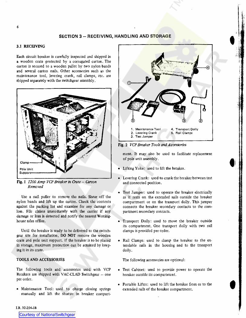
Each circuit breaker is carefully inspected and shipped in a wooden crate protected by a corrugated carton. The carton is secured to a wooden pallet by two nylon bands and several carton nails. Other accessories such as the maintenance tool, levering crank, rail clamps, etc. are shipped separately with the switchgear assembly.
Pole Unit Supportc------'
Fig. I 1200 Amp VCP Breaker in Crate - Carton Removed
' '
Use a nail puller to remove the nails. Shear off the nylon bands and lift up the carton. Check the contents against the packing list and examine for any damage or loss. File claims immediately with the carrier if any damage or loss is detected and notify the nearest Westinghouse sales office.
Until the breaker is ready to be delivered to the switchgear site for installation, DO NOT remove the wooden crate and pole unit support. If the breaker is to be placed in storage, maximum protection can be attained by keeping it in its crate.
TOOLS AND ACCESSORIES
The following tools and accessories used with VCP Breakers are shipped with VAC.CLAD Switchgear - one per order.
• Maintenance Tool: used to charge closing springs manually and lift the shutter in breaker compart-
J.B. 32-254-lB
1. Maintenance Tool 4. Transport Dolly 2. Levering Crank 5. Rail Clamps 3. Test Jumper
Fig. 2 VCP Breaker Tools and Accessories
ment. It may also be used to facilitate replacement of pole unit assembly.
• Lifting Yoke: used to lift the breaker.
• Levering Crank: used to crank the breaker between test and connected position.
• Test Jumper: used to operate the breaker electrically as it rests on the extended rails outside the breaker compartment or on the transport dolly. This jumper connects the breaker secondary contacts to the compartment secondary contacts.
• Transport Dolly: used to move the breaker outside its compartment. One transport dolly with two rail clamps is provided per order.
• Rail Clamps: used to clamp the breaker to the extendable rails in the housing and to the transport dolly.
The following accessories are optional:
• Test Cabinet: used to provide power to operate the breaker outside its compartment.
• Portable lifter: used to lift the breaker from or to the extended rails of the breaker compartment.
•
tJ
•

,,...,) Breakers - Weights in Pounds (Approx.)
Cunent Current Type Of Rating Type of Rating Breaker Amps Lbs Breaker Amps Lbs
1200 450 1200 450 50VCP250 2000 550 150VCP500 2000 550
3000 650 3000 650
1200 450 1200 450 50VCP350 2000 550 150VCP750 2000 550
3000 650 3000 650
1200 450 1200 450 75VCP500 2000 550 l50VCPl000 2000 550
3000 650 3000 650
3.Z HANDLING
The breaker is secured to the crate by a clamp on each foot. When it is ready for installation, remove these clamps. A lift yoke is provided with each order. Position this lift yoke on the top of the breaker so that side Jugs snap into breaker side holes and the J.3/4-inch diameter hook hole in the yoke is facing the pole units. It is recommended that the portable lifter (optionally provided) be used to lift the breaker. The crate should be raised on 2 x 4 or 4 x 4 blocks to permit the breaker lifting de-
Fig. 3 Breaker Lifting Yoke In Position
7
vice legs to run underneath the crate, If the portable lifter is not available, any lifter may be used provided that it Is rated for at least 1000 lbs.
When moving the breaker on flat level floors, place it on the transport dolly (one provided per order). Use the hand-holds to align the breaker on the transport doily rails, DO NOT USE primary disconnects. Use the rail clamps to securely hold the breaker to the dolly rails.
l ·~ " -i----®
1. Lifting Yoke 2. Portable Lifter
@
3. Trenoport Dolly 4. VOP areeker
Fig. 4 VCP Breaker Being Lowered on Transport Dolly
3.3 STORAGE
If the circuit breaker is to be placed in storage, maximum protection can be attained by keeping It in the original wooden crate. Before placing It In storage, checks should be made to make sure that the breaker is free from ship· ping damage and in satisfactory operating condition.
The breaker is shipped with its contacts open and closing springs discharged. The indicators on the front
l.B. 32-254-lB

f 8
I
)
. ;
./
panel should confirm this. Insert the spring charging handle In the slot to the left of the "push-to-close" button. Charge the closing springs by pumping the han· die up and down about 20 times until crisp metallic "click" Is ,heard. This Indicates that the closing springs are charged and is shown by the closing spring "charged" (yellow) indicator. Remove the spring operating handle. Operate the "push.to.close" button. The breaker will close as shown by the breaker contacts "closed" (red) indicator. Operate the "push-to.open" button. The breaker will trip as shown by the breaker contacts "open" (green) indicator. After completing this initial c!ieck, leave the closing springs "discharged .. and breaker con. tacts 0 open ".
Outdoor storage is not recommended. If unavoidable, the outdoor location must be well drained and a tern· porary shelter from sun, rain, snow, corrosive fumes, dust, etc. must be provided. Containers should be ar· ranged to permit free circulation of air on all sides, and temporary heaters should be used to minimize condensation. Moisture can cause rusting of metal parts and deteri· oration of high voltage insulation. A heat level of approx· lmately 400 watts for each JOO cubic feet of volume ls recommended with the heaters distributed uniformly throughout the structure near the floor. If the circuit breakers are stacked for storage, the stacks should be limited to two high.
Indoor storage should be in a building with sufficient heat and circulation to prevent condensation. If the building is not heated, the same general rule for heat as for outdoor storage should be applied.
When convenient, completely assembled circuit break· ers may be stored in their switchgear housings in the test · position. If they are stored for any length of time, they should be periodically inspected to see that rusting has not started and that they are in good mechanical con. dition.
J.B. 32-254-l]l
Fig. 5 VCP Breaker Escutcheon Plate
•

.. ~
•
9
SECTION 4 - INSTALLATION
4.1 INITIAL BREAKER AND COMPARTMENT PREPARATION
Before attempting to place the breaker In service, It Is important to check Its compatibility with the switch· gear compartment. Compare the breaker nameplate In· formation with the compartment drawings. Make certain that the power rating of the breaker Is as high or higher than switchgear rating and the control voltages are com· patible. In order to assure that only breakers with ade. quate ratings can be Inserted Into the switchgear compart· ment, a set of code plates are provided on the breaker and in the compartment - see Fig. 6. If the breaker rating is not adequate, the mismatching code plates prevent the breaker from being Inserted into the test position and In tum being levered .In.
Code plates do not check breaker control compati· billty .
The lnterphase barrier for type VCP breakers Is part of the switchgear compartment. A safety Interlock Is provided that prevents the Insertion of the breaker Into the test po· sitlon unless the barrier Is already In place, The barrier lit • shipped In the breaker compartment and is held In place with string to protect It from damage during transporta. tion. REMOVE THIS STRING.
Having confirmed the breaker/compartment compatl· bility and presence of the lnterphase barrier, connect the male end of the test jumper to the secondary disconnect in the compartment. The female end will be con· nected to the breaker secondary disconnect later. Pull the rails all the way out as Indicated by dropping of the front end down a little and placing the rail In a stable horizontal position.
1. Compartment Code Plates 2. lnterphase Barrier
6. Levering Device Clutch 11. MOC Switch Plungers
3. Secondary Disconnects 4. Levering Release Latch 6. Leverlng Socket
7. Levering Device Drive Nut 8. Levering Device Drive Screw 9. Floor Tripper and Trip Rall
10. Floor Tripper and Spring Rel8ase Rail
Fig. 6 VA C·CLAD Switchgear Breaker Compartment
12. Key Interlock 13. Ground Contact Bus 14. Shutter Operator 16. lnterphase Barrier Interlock
I.B. 32-254·1B

10
As described in the handling section the breaker is resting on the transport dolly. It should be open and the closing springs should be discharged. Move the dolly near the switchgear. Remove the rail clamps that are holding the breaker feet to the transport dolly. Llft the breaker with the portable lifter and lifting yoke. Gently and carefully lower it on the extended rails. Clamp the breaker feet on rails as shown in Fig. 9. Move the portable lifter and the llfting yoke away from the breaker.
1. Breaker Code Plates 2. Compartment Code Plates
3, lnterphase Barrier 4. Extendable Rall
Fig. 7 VCP Breaker in the Process of Installation
4.2 MANUAL BREAKER OPERATION
The breaker is now in the withdrawn position on the extended rails. Manually charge the closing springs. Place the bent slotted end of the maintenance tool into the slot on the left hand side of escutcheon plate. Charge springs with about 20 downward strokes of the handle until a crisp metallic cllck is heard and closing springs charged/ discharged indicator shows "charged". Remove the handle.
Depress the "push to close" button. The breaker will close as indicated by the breaker contacts "closed" indicator. The closing springs indicator will show "discharged".
Note the operation counter reading. Depress the "push to open" button. The breaker will open as indicated by breaker contacts "open". The counter readings will advance by one.
Manual breaker operation may also be checked while the breaker is resting securely on the transport dolly as shown in Fig. 7.
I.B. 32-254-JB
1. Portable Lifter 2. Llftln9 Yoke 3. Ext.;indable Rall
4. Circuit Breaker _6. Pole·Unlt Assembly 6, Primary Disconnect
Fig. 8 VCP Breaker Being Lowered on Extended Rails
1. Circuit 13raaker 2. Extendable Rall 3. Rall Clamp
Fig. 9 VCP Breaker In Withdrawn Position on Extended Rails

~ . I
4,3 VACUUM INTERRUPTER INTEGRITY CHECK
Using a dry lint·free cloth or a paper towel, clean all the insulating surfaces of the pole units. Conduct a vacuum interrupter integrity check as described Jn the malnte. nance Section 6.2.
4.4 CONTACT WEAR GAP CHECK
Manually charge the closings springs and close the breaker. Check the contact wear gaps for each pole. The wear gaps should be ,56 to .62 lnches. Record the wear gap for comparison. with future values in order to determine contact erosion. See Fig. 19.
4.S PRIMARY CffiCUIT RESISTANCE CHECK
Check the primary circuit resistance as described in the Maintenance Section 6.6. The resistance should not exceed the values specified.
Trip the breaker.
4.6 ELECTRICAL OPERATION CHECK
As described at the end of Section 4.1, one end of the test jumper is already connected to the breaker compartment disconnects. Now connect the other end of the test jumper to the breaker secondary disconnect plugs. If the secondary control circuit is energized, the spring charging motor will immediately start charging the closing springs as soon as the secondary contacts are engaged. As soon as the closing springs are completely charged, the motor will automatically tum off, Using the control switch on the door, close the breaker. As soon as the breaker closes, the motor will immediately recharge the closing springs.
Trip the breaker using control switch on the door. Tum off the control power. Manually close and trip the breaker. Disconnect the test jumper from the breaker and the compartment and remove it.
Electrical operation check may also be made with the breaker securely resting on transport dolly as shown in Fig. 10.
If a test cabinet is available, it may be used to perform the electrical operation check.
4.7 BREAKER/COMPARTMENT INTERFACE CHECK
Remove the rail clamps. Using the hand-holds push the breaker into the compartment. Test position is reached when levering latch under the breaker engages the levering device nut in the compartment as indicated by a crisp metallic sound, Push the rails into storage position.
Fig. 10 VcP Breaker· Electrical Operation Check on Transport Dolly
II
Pull the secondary disconnects in the compartment forward as far as possible, The secondaries are now engaged and latched. If the control circuit is energized, the motor will automatically start charging the closing springs. Motor will stop as soon as the charging is completed.
Electrically close and open the circuit breaker several times. With the breaker closed and the closing spring charged, electrically short the control switch "close" contact with a test jumper. Tum the. control switch to the "trip" position to trip the breaker. Even though the close circuit is made through the jumper the breaker will not close because of the anti-pump circUlt in the control scheme. Remove the test jumper.
Engage the levering crank in the levering socket. Engagement requires pushing the crank forward as far as possible.
Turn the crank clockwise to move the breaker to· wards the connected position. Some increase in turning,
~
1. Ground Contact Bus 2. Secondary Disconnect
Handle 3. Levering Socket
4. MOC Switch 6. Compartment Code Plates 6. Circuit Breaker Code Plates 7. MOC Operator
Fig. 11 VCP Breaker in Connected Position
l.B. 32-254-JB

12
•ffort will be experienced when the primary disconnects initially engage the stabs. The connected position is reached when the crank begins to turn "spin free". Additional turning will not result into any forward movement of the breaker. Remove the crank.
Operate the breaker several times to check its operation in the connected position. With the breaker closed and springs charged, attempt to engage the levering crank. The crank cannot be engaged unless the breaker is tripped. Trip the breaker. Engage the levering crank and turn it counterclockwise to bring the breaker to the test position. This position is indicated by "spin free" turning of
J.B. 32-254-lB
the crank. Additional turning will not result into any motion of the breaker. Remove the crank. Make certain that the crank is turned counterclockwise until it is "spin free".
Pull the secondary disconnects forward as far as possible. Close the breaker. As before, the motor will start and charge the closing springs. Holding the levering latch release up, pull the breaker forward with the hand holds. The breaker will automatically trip, close and trip. Thus as the breaker is pulled out to the withdrawn position it is always open with the closing springs discharged. Push the breaker back into the test position.
\ l
0 f
* ~:-f::t , __ .
' '
13
SECTION 6 - DESCRIPTION AND OPERATION
GENERAL
Westinghouse type VCP Breakers are horizontal draw out vacuum circuit breakers. They are designed for use in VAC.CLAD Metal·Clad switchgear compartments. Most ratings can be stacked two high in a vertical section which results in considerable savings in floor space. They use sealed vacuum interrupters to close and open the primary circuit. The mechanism is front mounted spring-stored energy type which not only aids personnel safety but also provides ease of inspection and accessibility for servicing. The same basic mechanism is used for all ratings, Thus a minimum investment in spare parts ls required. All primary insulation to ground ts porcelain which can be easily cleaned. Due to the inherent long life characteristics of the vacuum interrupters, highly reliable spring-stored energy type mechanism and primary porcelain insulation, type VCP circuit breakers provide long trouble free service with minimum maintenance.
5.1 INTERRUPTER ASSEMBLY
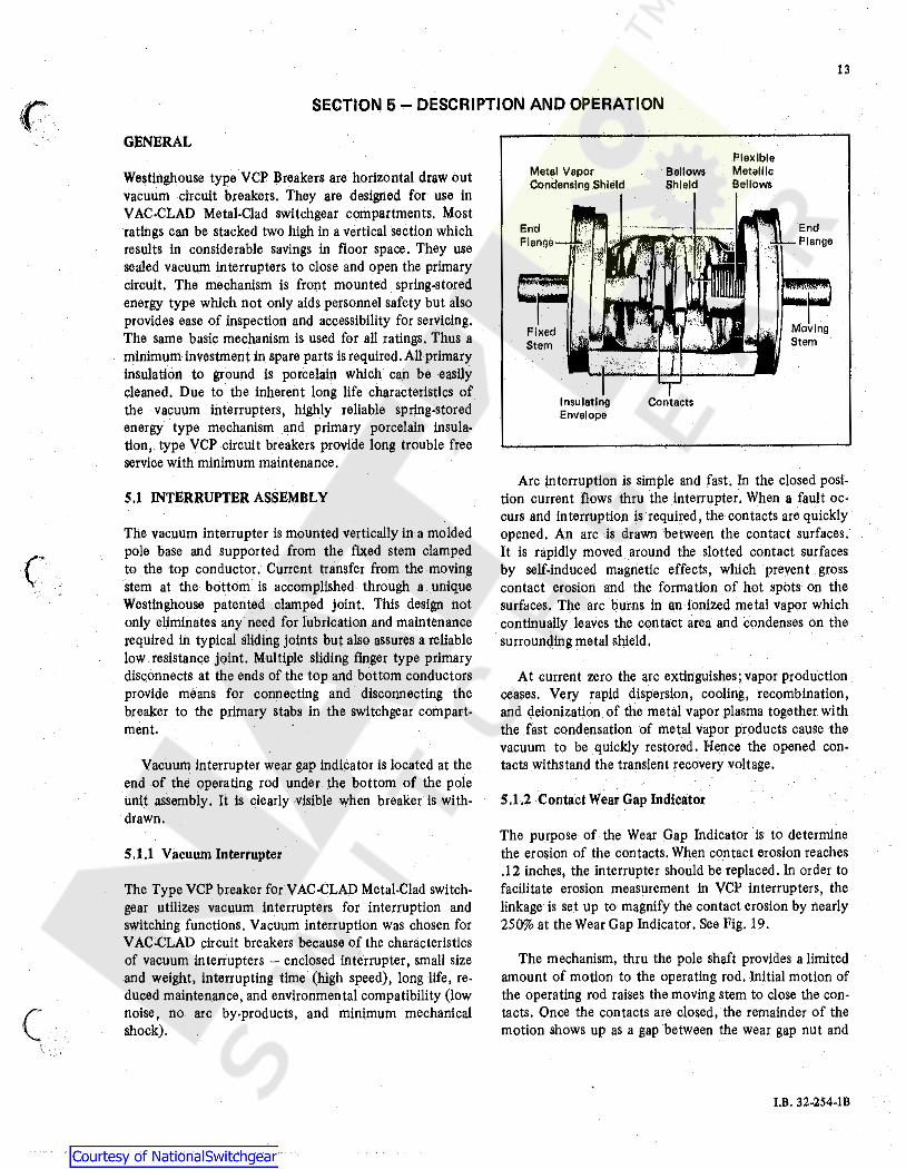
The vacuum interrupter is mounted vertically in a molded pole base and supported from the fixed stem clamped to the top conductor. Current transfer from the moving stem at the bottom is accomplished through a unique Westinghouse patented clamped joint. This design not only eliminates any need for lubrication and maintenance required In typical sliding joints but also assures a reliable low resistance joint. Multiple sliding finger type primary disconnects at the ends of the top and bottom conductors provide means for connecting and disconnecting the breaker to the primary stabs in the switchgear compartment.
Vacuum interrupter wear gap indicator ls located at the end .of the operating rod under the bottom of the pole unit assembly. It is clearly visible when breaker is withdrawn.
S.1.1 Vacuum Interrupter
The Type VCP breaker for VAC-CLAD Metal-Clad switchgear utilizes vacuum interrupters for interruption and switching functions. Vacuum interruption was chosen for VAC-CLAD circuit breakers because of the characteristics of vacuum interrupters - enclosed interrupter, small size and weight, interrupting time (high speed), long life, reduced maintenance, and environmental compatibility (low noise, no arc by-products, and minimum mechanical shock).
Metal Vapor Condensing Shield
End Flange
Fixed Stem
Bellows Shield
Flex Ible Metelllo Bellows
Arc interruption is simple and fast. In the closed position current flows thru the interrupter. When a fault oc· curs and interruption is required, the contacts are quickly opened. An arc is drawn between the contact surfaces. It is rapidly moved around the slotted contact surfaces by self-induced magnetic effects, which prevent gross contact erosion and the formation of hot spots on the surfaces. The arc burns in an ionized metal vapor which continually leaves the con tact area and condenses on the surrounding metal shield.
At current zero the arc extinguishes; vapor production ceases. Very rapid dispersion, cooling, recombination, and deionizat!on of the metal vapor plasma together with the fast condensation of metal vapor products cause the vacuum to be quickly restored. Hence the opened contacts withstand the transient recovery voltage.
S.1.2 Contact Wear Gap Indicator
The purpose of the Wear Gap Indicator is to determine the erosion of the contacts. When contact erosion reaches .12 inches, the interrupter should be replaced, In order to facilitate erosion measurement in VCP interrupters, the linkage is set up to magnify the contact erosion by nearly 250% at the Wear Gap Indicator. See Fig. 19.
The mechanism, thru the pole shaft provides a limited amount of motion to the operating rod. Initial motion of the operating rod raises the moving stem to close the c.on· tacts. Once the contacts are closed, the remainder of the motion shows up as a gap between the wear gap nut and
I.B. 32-254-18

14
the spring yoke. Due to erosion, the gap between moving _:_·'~nd fixed stem contacts increases. This requires more · ·-···1notion to close the con tacts and less is available for
wear gap. Thus, as the contacts erode the wear gap goes down, the difference being proportional to erosion.
The wear gap is set to .56 to .62 inches at the factory. When it goes down to .31 inches it approximates .12 inches of erosion. There is a step on the spring yoke surface. When the front edge of the nut approximately lines up with this step, the gap is nearly .31 and it is time to replace the vacuum interrupter. It is very unlikely that the interrupter will have to be replaced due to erosion of contacts. However, wear gaps should be recorded at the time of installation to make determination of the need for replacement.
Note that the wear gap nut is not an adjustment nut and must not be tampered with.
5.2 MECHANISM
The spring-stored energy operating mechanism is mounted in the front of the breaker. It includes all the elements for storing the energy, closing and tripping of the breaker, manual and electrical controls, and in ter!ocks. Manual
---1" ontrols are all in the front and readily accessible. Poree·. · lain insulators in the rear are used to mount the vacuum
interrupter assemblies. Mechanical motion to close and open the interrupter contacts is provided thru porcelain operating rods connecting this mechanism pole shaft to the bell cranks of the interrupter assemblies.
The mechanism is mechanically trip free. The closing springs may be charged manually with the maintenance tool or electrlcally thru the charging motor. The interrupter is closed by releasing the energy stored in the closing springs either manually or electrically. The energy released by the closing springs closes the contacts, charges the contact loading springs, charges the reset spring and overcomes the friction encountered during the closing operation. The breaker may be opened manually or electrically with the energy stored in the contact loading springs and reset spring.
Fig. 12 shows the front view of the stored energy mechanism.
5.2.l Operation of Stored Energy Mechanism
The spring-stored energy mechanism stores the closing .. ··1nergy by charging the closing springs and applies the \._,./ eleased energy to close the breaker, charge the contact
J.B. 32-254-IB
loading springs and reset spring. The mechanism may rest in any one of the four positions shown in Fig. 14 as follows:
a. Breaker open, closing springs discharged b. Breaker open, closing springs charged c. Breaker closed, closing springs discharged d. Breaker closed, closing springs charged
Closing Springs Charging
Fig. 13 shows the schema tic views of the spring charging parts of the stored energy mechanism.
The major component of the mechanism is a cam shaft assembly which consists of a hex shaft to which are attached two closing spring cranks (one on each end), the ratchet wheel and the closing cam.
The ratchet wheel is actuated by a ratcheting mechanism driven by an electric motor. As the ratchet wheel rotates, the closing spring cranks and the closing cam rotate with it.
The closing spring cranks have spring ends connected to them which are in turn coupled to the closing springs. As the cranks rotate, the closing springs get charged.
Fig. 13a and 13b are schematic views of the spring charging portions of the stored energy mechanism. Fig. l 3a shows the springs charged, breaker closed position. Fig. l 3b shows the springs discharged, breaker open position. Rotation of the motor eccentric causes the driving plate and motor ratchet lever to oscillate. The drive pawl, part of the ratchet lever assembly, also oscillates rotating the ratchet wheel counterclockwise. As the ratchet wheel rotates, the spring cranks also rotate pulling the spring ends with them to charge the closing springs (one extension spring on each end of the cam shaft).
Closing Operation
When the closing springs are completely charged, the spring cranks go over center and the closing stop roller
comes against the spring release latch Fig. 13a. The closing springs are now held in charged position. They can be released to close the breaker by moving the spring release latch out of the way. This is done manually or electrlcally by depressing the spring release lever which turns the spring release "D" shaft thru the spring release wire. The force of the closing springs rotates the cam shaft thru springs cranks. The closing cam being attached to the cam shaft also rotates causing the breaker to close.
,-•'-.
i\'t
~·

~·
'" )
Fig. 14 shows the positions of the closing cam and trip· ping linkage. Note that in 14a in which the breaker is open and the closing springs discharged, the trip "D" shaft and the trip latch are in the unlatched position. As the closing springs are charged, the trip latch snaps into the fully reset or latched position as in 14b near the end of spring charging operation.
In Fig. l 4c the linkage is shown with the breaker in the closed position and before the closing springs have been recharged. Note that the closing cam has rotated about one-half turn corresponding to the rotation of the cam shaft and the ratchet wheel of Fig. 13. Rotation of the closing cam pushes the main link roller downward so as to
CD
®
®
© ®
®
1, Name·Plate 2. Auxiliary Switches 3. L.H. Closing Spring 4. L.H. Closing Spring Crank Pin 6. Charging Ratchet 6. Pole Shaft 7. TOC Operator 8. Spring Release Device
15
rotate the pole shaft of the breaker and close the contacts. This is possible because the restraining links between the main link roller and the trip latch prevent the main link roller from moving off the cam to the left. The restraining links cause the trip latch to push against the trip "D" shaft. Fig. 14d shows the breaker in the closed position after the closing spring has been recharged. Note that the closing cam has rotated about one.half turn.
The cam for this portion of the travel is cylindrical and causes no further movement of the main link roller. This rotation corresponds to the spring charging rotation of the ratchet wheel shown in Fig. 13.
9. Shunt Trip Device 10. Spring Charged/Discharged Indicator Cam 11. R.H. Closing Spring Crank Pin 12. Dash Pot 13. R.H. Closing Spring 14. Reset Spring 15. Spring Charging Motor
Fig. 12 VCP Breaker in Test Position -Front Panel Removed
J.B. 32-254-lB

16
" f"'\i f /,.'
'v 1. Pole Shaft
~" 2. Anti Close Interlock 3. Spring Release Latch
9 4. Spring Release "D" Shaft 6. Spring Release Shaft Lever 6, Spring ReleaseWlre 7. Spring Crank 8. Closing Spring 9. Closing Spring
Fixed End ® 10. Closing Spring ® Charging Motor @
® 11. MotorCrank ~ @ 12. Motor Ratchet Lever
@ 13. Drive Pawl ® ~ @) 14. Ratchet Wheel
~ ~ 0 16. Holding Pawl 16. Spring Release Lever ~ !('.) 11. Spring Release Coll
f: ~-- 18. Closing Latch Roller 19. Cam Shaft
~-- 20. Drive Plate
8 @
I ea
11
1 @ (
\J
Fig. 13a Breaker Closed, Springs Charged Fig. l3b. Breaker Open, Springs Discharged
Fig. 13 Stored Energy Mechanism
J.B. 32.254-lB

17
Fig. 14a Breaker Open & Closing Spring Not Charged Fig. 14c Breaker Closed & Closing Spring Not Charged
1. Pole Shaft 2. Main Link 3. Restraining Links 4. Trip Latch
5 6. Trip "D" Shaft 6. Trip Shaft Lever 7. TrfpWlre 6 8. Shunt Trip Lever 9. Shunt Trip Coil
10. MOC Operator 11. Cam Shaft 12. ClosingCam 13. Operating Rod 14. Main Link Roller
8
9
Fig. 14b Breaker Open & Closing Spring Charged Fig. 14d Breaker Closed & Closing Spring Charged
Fig. 14 Four Positions of Closing Cam and Trip Linkage
l.B. 32-254-lB

18
Opening Operation
Depressing the shunt trip lever either by hand or by the shunt trip coil turns the trip "D" shaft thru the trip wire and permits the trip latch to turn counterclockwise under the influence of contact loading springs via main link and restraining link. This permits the linkage to collapse and open the breaker. The linkage then assumes the position shown in Fig. 14b.
S .2.2 Interlocks
All VCP breakers are equipped with several interlocks. These interlocks permit proper breaker operation and prevent improper breaker operation.
5.2.2.I Breaker - Compartment Code Plates
A set of two code plates on the breaker and two in the compartment form this interlock. It ls intended to prevent insertion of lower rated breaker into higher rated compartment (except for 3000 amp breaker and 3000 amp compartment which require matched breaker and compartment). The ratings are based on continuous current, interrupting current, close and latch current and maximum voltage. Breaker with the same or higher rating in all
. ' of the above categories can be inserted into the compart· ment of equal or lower rating. If the ratings do not agree as required, the breaker cannot be inserted into the test position. This prevents engaging the levering-in device. See Fig. 11.
NOTE: Code plates do not check control compatibllity.
5.2.2.2 Anti.Close Interlock
This is an interlock that prevents releasing the closing springs electrically or manually when the breaker is closed - see Fig. 13a. Regardless of how the spring release "D" shaft may be rotated, the spring release latch is prevented from getting out of the way of roller by the anti-close interlock.
S.2.2.3 Floor Tripping and Spring Release Interlocks
These interlocks are operated by the interaction between the floor tripper rollers (Fig. 15) on the bottom of the breaker and levering device rails or interlock operator surfaces (Fig. 6). They perform several functions:
1. Hold the breaker in the trip free mode between the test and connected positions. The latch check switch is also held open thus preventing any electrical close signal.
l.B. 32-254-lB
2. Permit the breaker to be withdrawn in safe mode (breaker open, springs discharged) when moved from the test to the withdrawn position or vice versa. Note that there ls never a free discharge of the closing springs that unduely imposes heavy stresses on the mechanism parts.
3. Trip \he breaker (if closed) before being levered from test position.
The above functions are accomplished by pushing up the tripper rollers which in turn rotate the trip or spring release "D" shafts.
5.2.2.4 Levering Interlock
The purpose of this interlock is to prevent engaging the levering crank when the breaker ls closed in the con. nected position. A tab on the right hand side of the levering slide cage interferes with the breaker MOC switch operator preventing the slide from moving far enough to engage the levering crank.
5.2.2.5 Interphase Barrier Interlock
This interlock is part of the switchgear compartment. It prevents insertion of the breaker in the compartment if the barrier ls not in place. The barrier pushes the barrier interlock lever on the right hand side which would otherwise interfere with the breaker. See Fig. 6.
S.2.3 Control Schemes
There are two basic control schemes for type VCP breakers - one for d-c control and one for a-c control. See Fig. 16. There may be different control voltages or more than one tripping elements, but the principal mode of operation is as follows:
As soon as ·the secondary disconnects make up, the spring charging motor automatically starts charging the closing springs provided the control power ls available. When the springs are charged, the motor cut off switch turns the motor off. The breaker may be closed by making
up control switch close(cg )contact. Automatically upon
closing of the breaker, the motor starts charging the closing springs. The breaker may be tripped any time by
making up control switch trip (~)contacts. Note the
position switch contact in spring release circuit In the d-c scheme. This contact makes before the secondary disconnects make and break after they make. This feature pre-

•
1. Breaker Code Plates 2. MOC Operator 3. Floor Tripper· Trip 4. Levering Latch 6. Floor Tripper ·Spring Release 6. Secondary Disconnects 7. TOC Operator
Fig. 15 VCP Breaker Rear Bottom View
vents the breaker from closing automatically even though control switch close contact may have been made while the breaker is levered to connected position.
5.2.4 Undervoltage Trip Device
The Undervoltage Trip Device shown in Fig. 17 is an electromechanical device that trips the circuit breaker when the voltage on its coil falls to between 60 and 30 percent of nominal.
In operation with nominal voltage on coil, the moving core is held to the stationary core by magnetic force against the roller lever torsion spring. The moving core is linked to the roller lever which restrains the trip lever.
8. Ground Disconnect 9. Operating Rod
1 o. Contact Loading Spring 11. Spring Yoke 12. Ball Crank 13, Primary Disconnect 14. Pole Base
19
wlien the coil voltage is reduced sufficiently, the roller lever spring overcomes the magnetic force between two cores. 'rhe moving core moves up and rotates the roller lever clockwise so that the roller moves out of the way of the trip lever. A torsion spring around the pivot pin of the trip lever then rotates it clockwise causing the trip wire to turn the trip "D" shaft and trip the breaker. As the breaker opens, a pin on the right pole reset lever operates the undervoltage trip device reset linkage which lifts up the right hand end of the trip lever turning the roller lever counterclockwise and reseting the moving core. As long as breaker is open, this position Is maintained. If the trip device coil has at least 85% of nominal voltage, the breaker may be closed. Otherwise upon attempting to close, it will automatically trip out .
I.B. 32.2s4.rn

20
N
7
y
LS PS y
6
R9 R!O
R PR
RS
· QI. I; ; I; ~ Rt 1 Rl2 VL2 'V'L4 'V'LS VLB
I I I I I I I I I I I I I I I I I I I I I I I I I I I I I I I I I I
OPTIONS
~11
UV
'V'L12
ANSI STANDARD VCP BREAKER DC CONTROL SCHEMATIC !·
R!!
R9
R12
CAP TRIP Dl':V
1-l l\C
..0.L 11
UV
'Vl12
OPTIONS
ANSI STANOllRO VCP BREl\KER AC CONTROL SCHEMATIC
cs c - Breaker Control Switch - Close
cs T - Breaker Control Switch - Trip
Y - Anti Pump Relay SR - Spring Release Coll (Close Co Ill M - Spring Charging Motor TC -Trip Coll
PR - Protective Relay LS - Limit Switch (Motor Cut.off) LC - Latch Check Switch UV - Undervoltage Coll PS - Position Switch
Mechanically actuated to make as breaker moves from test position and to break In connected position as leverlng.ln crank Is removed.
Fig. 16 Typical 'AC' and 'DC' Control Schemes
I.II. 32-254-lB

1. Trip Pin 2. Trip Wire 3. Trip Lever 4. UV Coll 6. Moving Core
6. Stationery Core 7. Plunger S. Pole Shaft 9. Roller Lever
Fig. 17 Undervoltage Trip Device
Note that with undervoltage trip device, the breaker cannot be closed unless proper voltage ls applied to the undervoltage coil. These devices are available for d-c con. trol voltages only.
5.2.6 Secondary Disconnect
The breaker control· wiring is arranged for drawout disconnecting by a set of two 12 point (total 24 points) male plugs arranged to connect to a corresponding set of female plugs mounted in the switchgear compartment. The breaker plugs are mounted on the left side under the bottom pan of the mechanism and they are fixed in that position. The female plugs in the compartment are mounted on a movable carriage. See Figs. IS and 6. The disconnect will engage automatically as the breaker is levered Into the connected position.
21
To engage the secondary disconnects while the breaker is in test position, pull the carriage all the way towards the front. This will latch the disconnects.
S .2.7 Ground Contact
The Ground Contact Is an assembly of spring loaded fingers similar to the 1200/2000 amp primary disconnect to provide a means for grounding the breaker chassis when it Is inserted Into the switchgear compartment. The ground contact Is located on the left hand side of the breaker under the mechanism bottom pan. An extension of the switchgear ground bus is secured to the compartment floor In such a position to engage the ground contact when the breaker is pushed Into the test position and to remain engaged In all positions of the circuit breaker from the test position to and including the connected position. See Figs. IS and 6.
5.2.8 MOC and TOC Switch Operators
As shown in Fig. 14, the MOC (Mechanism Operated Control) switch operator is coupled to the pole shaft. In the test and connected positions of the breaker, this operator aligns directly above the MOC switch plungers in the compartment. As the breaker closes, the operator moves down and pushes the switch plunger to change. the MOC switch contact positions. Thus MOC switch contact positions can be correlated with the breaker contact position in the same manner as the auxiliary switches mounted in the breaker. (Note that the MOC switch operator is provided on all breakers but MOC switches in the compartment are provided only when specified on the switchgear order).
As shown In Fig. 15, the TOC (Truck Operated Control) switch operator is mounted in the front of the mechanism in the center left position. It operates the roe switch as it moves to the connect position in the switchgear compartment.
S.3 INTERPHASE BARRIER
Unlike in most breaker designs, the interphase barrier for type VCP breakers is part of the switchgear assembly. An interlock is provided so that the breaker can be inserted only if the barrier is installed in the compartment. When the breaker is in the connected position, the barrier is in place to provide the interphase insulation. However when the breaker is withdrawn, the barrier remains in the com· partment. This design readily permits unobstructed inspection of the breaker in the withdrawn position. As shown in Fig. 7, the interphase barrier is a single piece design molded from high quality glass polyester.
l.B. 32-254-lB .

22
5,4 LEVERING DEVICE
The purpose of the Levering Device is to move the circuit breaker between the Test and Connected positions. Por VCP breakers, the device is drive screw and drive nut type with a clutch. Although the device is mounted in the switchgear compartment, a brief description here will help understanding the operation. See Pig. 18 and Pig. 6.
The levering device consists of a drive screw, a drive nut, a clutch, two side rails and a sliding cage. In the Test position, the nut is all the way to the front,. As the breaker ls pushed in, the levering latch snaps on the nut. Turning the crank clockwise while pushing forward advances the breaker toward the connected position. During this travel, the floor tripper "Trip" roller ls Ufted
J.B. 32-254-IB
up holding the breaker trip free. When the breaker reaches the connected position, the crank turns "Spin Pree" providing no further breaker movement.
If the breaker is closed in the connected position, the levering crank cannot be engaged. After tripping the breaker, the levering crank may be engaged and breaker withdrawn to the Test position by turning the crank counterclockwise. This position is indicated by "Spin Pree" turning of the crank.
The breaker levering latch may be disengaged by lifting the latch release. As the breaker is withdrawn from the test position, it comes out with contacts open and springs discharged because of the floor tripping and spring release Interlocks.

T-Levering·ln Crank (Accessories)
Coupling Clutch Assembly
Cage Assembly
Test Position
__ ... -..:-... _ - --
!Not the Tlavell 10.31 ± .03
Drive Nut Connected Position
Drive Screw
Connected Position
l.EVERING.tN DEVICE (DRIVE NUT SHOWN IN TEST OR CONNECT.ED POSITION)
Fig. 18 Levering Device Assembly
23
!.B. 32-254-IB

24
. SECTION 6 - MAINTENANCE
6.1 GENERAL
This class of power circuit breaker ls a protective device to prevent damage to more expensive apparatus and to maintain continuity of electric power service. To main· lain greatest reliability the breaker should be inspected and given all indicated maintenance on a regular schedule. Type VCP circuit breakers are designed to comply with standards requiring maintenance at least every 1000 to 2000 operations (depending upon rating) or once a year, whichever comes first.
Actual Inspection and maintenance will depend upon individual application conditions such as number of operations, magnitude of currents switched, desired overall system reliability and operating environment. Any time the breaker ls known to have an interrupted fault current at or near its rating, It is recommended that the breaker be Inspected and necessary maintenance be performed as soon as Is practical. Some atmospheric conditions such as extremes of dust and moisture or corrosive gases might indicate Inspection and maintenance at more frequent intervals than 1000 to 2000 operations. Very clean and dry conditions combined with low switching duty will justify longer times between inspection and maintenance operations. With experience, each user can set an Inspection and maintenance schedule which is most economical for the particular use.
Before attempting any maintenance work, take note of safety practices outlined earlier in this book:
MAKE CERTAIN THAT THE CONTROL CIRCUITS ARE DE-ENERGIZED AND THE BREAKER IS RESTING SECURELY CLAMPED EITHER ON THE EX· TENDED RAILS OUTSIDE THE SWITCHGEAR HOUSING OR ON TRANSPORT DOLLY. DO NOT WORK ON A CLOSED BREAKER OR A BREAKER WITH THE CLOSING SPRINGS CHARGED.
The following should be inspected and maintained every _2000 operations (1000 operations for 3000A breaker) or once a year, whichever comes first, until the schedule is· determined based on operating experience of the user.
6.2 VACUUM INTERRUPTER INTEGRITY TEST
Vacuum interrupters used in type VCP circuit breakers are highly reliable interrupting elements. Satisfactory performance of these devices is dependent upon the integrity of the vacuum in the interrupter and the internal di-
l.B. 32-254-lB
electric strength. Both these parameters can be readily checked by a one minute 36 KV A~ RMS high potential test. During this test, the following caution must be observed:
+q.iiliM,11
APPLYING ABNORMALLY HIGH VOLTAGE ACROSS A PAIR OF CONTACTS IN VACUUM MAY PRODUCE X·RADIATION. THE RADIATION MAY INCREASE WITH THE INCREASE IN VOLTAGE AND/OR DECREASE IN CONTACT SPACING.
X-RADIATION PRODUCED DURING THIS TEST WITH RECOMMENDED VOLTAGE AND NORMAL CONTACT SPACING IS EXTREMELY LOW AND WELL BELOW MAXIMUM PERMIITED BY STANDARDS. HOWEVER, AS A PRECAUTIONARY MEASURE AGAINST POSSIBILITY OF APPLICATION OF HIGHER THAN RECOMMENDED VOLTAGE AND/ OR BELOW NORMAL CONTACT SPACING, IT IS RECOMMENDED THAT ALL OPERATING PERSONNEL STAND AT LEAST ONE METER AWAY IN FRONT OF THE BREAKER.
High-Pot Testing
With the breaker open and securely resting either on the extended rails or the transport dolly, connect all top primary studs (bars) together and to the high potential machine lead. Connect all bottom studs together and ground them along with the breaker frame and secondary contacts. Start the machine at zero potential, increase to 36 KV A.C RMS, 60 Hz and maintain for one minute. Successful withstand indicates that all interrupters are satisfactory. If there Is a breakdown, the defective interrupter or interrupters should be identified by an lndi· vidual test and replaced before placing the breaker in service. During individual tests, it is recommended that a barrier be used in order to prevent phase to phase break· down - approximately 1/8 thick glass polyester will be satisfactory.
After the high potential is removed, discharge any elec· trical charge that may be retained.
To avoid any ambiguity in the a-c high potential test due to leakage or displacement (capacitive) current, the test unit should have sufficient volt-ampere capacity. It is recommended that the equipment be capable of deliver· ing 25 milliamperes for one minute.

Although an a-c high potential test is recommended, a d·c test may be performed if only a d-c test unit is avail· able. In this case, 40 kV d-c should be applied for one minute, and the test equipment should be capable of delivering 5 milliamperes for one minute to avoid amblgu· lty due to field emission or leakage currents.·
The current delivery capability of 25 mA a-c and S mA d-c apply when all three Vi's are tested in parallel. If Individual Vi's are tested, current capability may be one third of these values.
Note that the indicated high-potential test voltages of 36 kV rms a-c and 40 kV d·c apply Irrespective of whether the breaker voltage rating Is 5 kV, 7.5 kV, or 15 kV.
Some d-c high potential units, operating as unfiltered halfwave rectifiers, are not suitable for use to test vacuum Interrupters because the peak voltage appearing across the interrupters can be substantially greater than the value read on the meter.
6.3 CONTACT EROSION
Since the contacts are contained Inside the Interrupter, they remain clean and require no maintenance. However, during high current Interruptions there may be a minimal amount of erosion from the contact surfaces. Maximum permitted erosion ls .12 Inch, To determine contact erosion, close the breaker and measure the wear gap as shown in Fig. 19, The change In the wear gap between the time of installation and now divided by 2.5 gives the amount of erosion. However, a simple indication of .12 inch con tact erosion is given by the wear gap measuring nearly .31 inches - this corresponds to the leading edge of the wear gap nut lining up with the step on spring yoke.
It is extremely unlikely that the contact erosion will reach .12 Inch during normal lifetime of the breaker. However, In such a case, the vacuum interrupter assembly should be replaced.
6.4 INSULATION
In VCP breakers, all primary Insulation to ground is porcelain and thus requires minimal maintenance. Insula· tion maintenance primarily consists of keeping the lnsulat· Ing surfaces clean, This can be done by wiping off all Insulating surfaces with a dry lint·free cloth or dry paper towel. in case there is any tightly adhering dirt that will not come off by wiping, it can be removed with a mild
• Breaker Closed
The Weer Gap Indicator Shows that the Vacuum Interrupter Is In New Condition.
Breaker Closed
The Weor Clop Indicator Showsthat the Vacuum Interrupter needs to be Replaced.
Breaker Open
The Wear Gap Indicator Should Always Look Like this When the Vacuum Interrupter Is Open.
25
Ref. Fig. 16
Fig. 19 Wear Gap Indicator
solvent or distilled water. But be sure that the surfaces are dry before placing the breaker in service. If a solvent ts required to cut dirt, use Isopropyl alcohol. Do not use any type of detergent to wash the surface of a porcelain in· sulator as detergent leaves an electrical conducting residue as It dries.
Secondary control wiring requires Inspection for tight· · ness of all connections and damage to insulation.
Check the Insulation integrity as follows:
6.5 INSULATION INTEGRITY CHECK
Primary Circuit:
The integrity of primary Insulation may be checked by the a-c high potential test. The test voltage depends upon the maximum rated voltage of the breaker. For the breakers rated 4.76 KV, 8.25 KV, and IS KV, the test voltages are IS KV, 27 KV and 27 KV RMS, 60 Hz re· spectlvely, Conduct the test as follows:
J.B. 32-254-!B

<'
Close the breaker, Connect the high potential lead of the test machine to one of the poles of the breaker. Con· nect the remaining poles and breaker frame to ground. Start the maehlne with output potential at. zero and In· crease to the test voltage. Maintain the test voltage for one minute. Repeat the procedure for the remaining poles. Successful withstand Indicates satisfactory Insulation strength of the primary circuit.
If the d-c high potential machine Is used, make certain that the peak voltage does not exceed the peak of the corresponding a-c RMS test voltage.
Secondary Circuit:
Remove the motor leads, Connect alt points of the sec· ondary contact pins together with shooting wire. Connect this wire to the high potential lead of the test machine. Ground the breaker frame. Starting with zero, increase the voltage to 1125 RMS, 60 Hz. Maintain the voltage for one minute. Successful withstand indicates satisfactory insula· tlon strength of the secondary control cl.rcuit. Remove the shooting wire and reconnect the motor leads.
6,6 PRIMARY CIRCUIT RESISTANCE CHECK
Since the main contacts are inside the vacuum chamber they remain clean and require no maintenance at any time. Unlike most typical circuit breaker designs, VCP breakers do not have sliding contacts at the moving stem. They use a highly reliable and unique flexible clamp design that eliminates the need for lubrication and inspec· tion for wear.
If desired, the d-c resistance of the primary circuit may be measured as follows: close the breaker, pass at least 100 amps d-c current through the breaker. With a low resistance Instrument, measure resistance across the studs on the breaker side of the disconnects for each pole. The resistance should not exceed 60µ0, 40µ0 and 20µ0 for 1200 amp, 2000 amp and 3000 amp breakers respec· tlvely.
6.7 MECHANISM
Make a careful visual inspection of the mechanism for any loose parts such as bolts, nuts, pins, rings, etc. Check for
l.B. 32°254-lB
excessive wear or damage to the breaker components. Operate the breaker several times manually and etec· trically to make certain the operation Is crisp and without any sluggishness.
6.8 LUBRICATION
All parts that require lubrication have been lubricated during the assembly with molybdenum disulphide grease, Westinghouse M No. 53701QB. Over the period of time, this lubricant may be pushed out of the way or degrade. Proper lubrication at regular Intervals Is essential for maintaining the reilable performance of the mechanism. Once a year or every 2000 operations (1000 operations for 3000 amp breaker) whichever comes first, the follow· ing areas should be lubricated with light machine oil such as Mobil I applied sparingly:
1. Wire links ends. 2. Spring charged/discharged indicator cam surface. 3. Trip latch surface/trip pin mating surfaces. 4, Spring release latch/spring release pin mating surfaces. 5. Closing and opening springs crank pins. 6. Beil crank pins in pole unit area.
After lubrication opeiate the breaker several times making sure that opening and closing operations are crisp and snappy.
Roller bearings are used on the pole shaft, the cam -shaft, the main link and the motor eccentric. These bear· ings are packed at the factory with a top grade slow oxldiz· ing grease which should be effective ·ror rnany years. They should not be disturbed unless there Is definite evidence of sluggishness or dirt, or unless the parts are dismantled for some reason.
If it becomes necessary to disassemble the mechanism, the bearings and related parts should be thoroughly cleaned of old grease In a good grease solvent. Do not use carbon tetrachloride. They should then be washed in light machine oil until the cleaner Is removed. After the oil has been drawn off, the bearings should be packed with Westinghouse Grease 53701.QB or equivalent.
0

•
•
27
SECTION 7 - RENEWAL PARTS
GENERAL
In order to minhnize production downtime, It Is recom· mended that an adequate quantity .of spare parts be carried In stock. The quantity will vary from customer to customer, depending upon the service severity and continuity requirements. Each customer should develop his own stock level based on operating experience.
The following items In the quantity specified may be used as guide:
7.1 RECOMMENDED RENEWAL PARTS FOR VCP CIRCUIT JJREAKER
Description
Interrupter Assemblies:
Qty.
SOVCP250-1200A - 58 kA. • • • • • • . • • . • . . • . . 3 H50VCP250-1200A - 78 kA. . • • • . • . . • • . • • • . 3 50VCP250-2000A - 58 kA. . • • . • • • • • . . • . • . . 3 H50VCP250-2000A - 78 kA. • . . . • . . • • • . . • • • 3 50VCP250-3000A - 58 kA. . • • . • • . • . • . • • . • . 3 H50VCP250-3000A - 78 kA. . • . . . • . . . . . • • . . 3
50VCP350·1200A - 78 kA. . • • . • • . • • • • • . . • • 3 50VCP350-2000A - 78 kA. • • • • • . . • . • • • • • . • 3 SOVCP350-3000A - 78 kA. • • • . • • • • • • • • . . • • 3
75VCP500-l 200A - 66 kA. . . • • • • • • . • • • • • • . 3 H75VCP500-l 200A - 78 kA. . • • . . . . . • • . . . . • 3 75VCP500-2000A - 66 kA. • • • . . . • . . • • • . • • • 3 H75VCPS00-2000A - 78 kA •..• , • • . • • . • . . . • 3 7SVCP500-3000A - 66 kA. • • • . • • . .. . . • . • • • 3 H75VCPS00-3000A - 78 kA •.•••.••• , . . • • . • 3
150VCPS00-1200A-37 kA................ 3 HI SOVCP500-l 200A - 58 kA, •.•••• , ••.• , . • 3 JSOVCP500-2000A - 37 kA. • • • • . • . • • • • • . • • 3 H150VCP500-2000A - 58 kA. . . • • . . • . . . . . • . 3 !SOVCPS00-3000A -37 kA, . • • . . . . . • • • • • • • 3 HISOVCP500.3000A- 58 kA............... 3
150VCP750-1200A - 58 kA. • • . . . • • • . • . . . . . 3 Hl50VCP750-1200A - 77 kA. • . • • . • • • • . . • • • 3 ISOVCP750-2000A - 58 kA. . . • • . . . • • . • . . • . 3 Hl50VCP750-2000A - 77 kA. . . . • . • .• • . . . • . . 3 ISOVCP750-3000A - 58 kA, . • • . . • • • • . • • . . . 3 HISOVCP750-3000A - 77 kA ..••.• , . • • • • . . • 3
ISOVCPIOOO-l200A- 77 kA. . • . . • • . . . • • . • . 3 150VCP1000-2000A- 77 kA. • . . • • . . • • . . . • • 3 ISOVCPI000-3000A- 77 kA. • . . . . • • • . . • • • • 3
Description Qty.
1200 Amp. Primary Disconnect • • • • • • • • • • • • • • 6 2000 Amp. Primary Disconnect • • • • • • • . • • • • • • · 6 3000 Amp. Primary Disconnect ••.••••••• , • • • 6
Operating Rods. . . . • . • • . . • . • . . • • • . . . • . . • 3
Spring Charging Motor 48VDC............................ 1 125 DC/120 AC • . • • . . . . • • . . . • • • . . • • • . l 250 DC/240 AC • . • . . • . . • . . . • . • • . . • • • • 1
Spring Release (Close) C9il 48VDC............................ 1 125VDC........................... l 250VDC ......•..••..........•.•... 1 120VAC........................... 1 240V AC........................... I
Shunt Trip Coil 48VDC............................ 1 !2SVDC ...••.••.....•............. 1 2SOVDC •...• ,..................... I
Anti-Pump Y Relay 48V DC .••.••.....•..•.•. ,......... 1 125VDC •..••••..••..•••..••.•.••.. I 250V DC........................... 1 120V AC with Rectifier • . . • . • . . . • • • • • . • • 1 240V AC with Rectifier . • • • . . . . • . . . • • • . . 1
Motor Cut-Off Switch ..••.•• , • . • • . . • . • • • • I Position Switch (DC Relay), •••.• , • • • • • • . . • . 1 Resistor (AC Relay) ...... , .......... ., • . . I Latch Check Switch. • • • . • • . • • . • • • • • . • • • . • 1
Auxiliary Switch (Standard Breaker). • • • . • . • • • • 2 Auxiliary Switch (Breaker with Trip No. 2) • . • . • • 3
Fastener Kit. . . . . . . . . • . . . . . . . . . • . . . . . . . 1
7 .2 ORDERING INSTRUCTIONS
• Always specify breaker rating information and shop order number.
• Describe the Item, give style number and specify the quantity desired.
• For electrical components, specify voltage.
• State method of shipment desired.
• Send all orders or correspondence to the nearest Westinghouse sales office.
I.B. 32-254-lB

l 'i
28
j[ .!
i
It •i
Fig. 20
l.B. 32-254-lB
Auxiliary Switches
Antlpump Relay
Spring Charging Motor
Spring Release (Closlng) Device
Shunt Trip Device
0

a, Table 1: Application: Available Breaker Types Rated on Symmetrical Current Rating Basis ~ ldentlficatlon Rated Values ( ' Nomlnat Nominal Voltage lnflulatlon Level Current Rated 1
Voltage 3-Phase Rated R41ted Rated Withstand Aated Rated Inter· Cfass MVA Maximum Voltage TestVoltaae Contln· Short roptlng
Class Voltage Range uous Circuit Time Factor Current Current
Circuit ereaker Type
Kv Class
VCP Vacuum Circuit Br••k•
60VCP260 4.16
H 60VCP250©
60VCP360
75VCP600 7.2
160VCP600
H 160VCP600©
160VCP760 13.8
' ) H 160VCP760$
160VCP1000
MVA crass
260
360
600
600
1----760
1000
E
Kvrms
4.76
8.26
16
© Non.Standard Breaker with High Momentary Rating avellable for Speclel Appllcatlons.
® For 3 phase and line to line faults, the sym Interrupting capablllty at a Kv operating voltage
E .. Jfv (Rated Short-Circuit Current)
But not to ll<ce.d Kl. $Ingle llne to ground fault capeblllty at a Kv operating voltage
.. 1.16 iv (Rated Short-Circuit Current)
But llotto axCMd Kl.
K
1,24
1.19
1.26
1.30
The above apply on predominately Inductive or resistive 3-phase circuits with normal·frequency line to Une re• covary voltage equal to the operating voltage.
•
low Fre· quency
Kvrma
19
36
38
Impulse
KvCrest
60
96
.
86
at (at 60 rated Ht Max,
Kvl ®
Amperes KArms Cycles
1200 2000 29 6 .,00
1200 2000 3000
1200 2000 41 3000
1200 33 6 2000 .,00
1200 2000 3000
1200 18 2000 3000
1200 29 6 2000 3000
1200 2000
"'"' 1200 2000 37 3000
@ For Reoloslng Service, the Sym. Interrupting CepabllJty and other related oapabltltles are modified by the reclos· Ing capablUtv factor obtained from the foll owl~ formula:
A(%)= 100-f ~n ~ 2) + 161~ T1+ 161Ja+.~ Where C = KA Sym. Interrupting CapabUlty at the Operat·
Ing Voltage but not less than 18. n = Total No. of Openings. T1, Ta, eto, ... Time Interval In seconds except
use 15 for time lntervala longer then 16 sec.
Note: Aecloslng Service wlth the standard duty cycle 0 + 16s +CO Does not require breaker Cap11bllltles modified since the Alclos· Ing capabllltyfactor A• 100% •
29
Related R<Jqulred Capabllltl ea4l Rated Rated Current Values Perm la· Max. Maxi· $Sec. Cloalng &Ible Voltage mum Short· &nd Tripping Divided Sym. Tlm& L.etohlng OOiey 8YK Inter• Current C.p•blllty
ruptlng Cirrylng fMomentary) Ca pa- CfpablUty blllty KTlmesRated 1.6KT1mea
© Short-Circuit Aated Short· Current$ Crroult
v E/K Kl Current
Sec. Kvrms KArme KA< ms KAtm$
2
2
2
.. 3.86 38 38
78(j)
4.0 48 48 78
6.6 41 41 66
..,
23 23 68(j)
11.6 36 38 68
n©
48 48 77
@Tripping may be delayed beyond the rated permlsslble tripping daisy at lower values of current In accordance wlth tha following formula: T ($econds) .., y fKI (I< Times Rated Short-Circuit CurrentMt
L: Short•Clrcu\t Curumt Through Sreaker:J The aggregate tripping delay on all Operations within any 30 minute period must notexcaed·thetlrne obtained frorn the above formula.
J.B. 32-254-IB

(
(,
cs" 1
RENEWAL PARTS DATA
GENERAL
This Renewal Parts Data will provide you with the proper indentifi<::ation of those Renewal Parts which you may require in the maintenance of this equipment.
The recommendations for stock are the minimum quantities that should be available for servicing this equipment. We feel that you are in a better position than we to decide how much you wish to inves't in Renewal Parts. The importance of minimizing shut-down time, together with the distance from source of supply and transportation facilities should be considered when ordering Renewal Parts.
PROCEDURE FOR IDENTIFYING RENEW ALP ARTS
1. Obtain the complete nameplate reading of the apparatus for which the part is desired.
2. Turn to the indicated Renewal Parts Data sheet where the desired part is described and identified, or to the equipment drawings.
3. If any part required is not identified in your Renewal Parts Data Sheets or drawings, give the complete nameplate reading of the apparatus and a
description of the parts needed.
ORDERING INSTRUCTIONS
All correspondence and orders should be addressed to the nearest sales representative of the Westinghouse Electric Corporation.

(
(
RPD 32-254 PL
RENEWAL PARTS
TYPE VCP CIRCUIT BREAKER
REFER TO IL32-254-1A FOR IDENTIFICATION
DESCRIPTION STYLE Fastener Kit 8061A01G01 Stationary Sec. Contact Kit 8261A65G01 Moving Sec. Contact Kit 8261A65G02 Ground Contact Cluster 8058A20G01 Motor Cutoff Switch 450D818G04 Latch Check Switch 8058A65G01 Upper and Lower Aux Switch 692C259G01 PRIMARY CONTACT ASSEMBLY (Finger Clusters) 1200 AMP Breaker 508B022G01 2000 AMP Breaker 508B012G01 3000 AMP Breaker 692C037G01
OPERATING ROD ASSEMBLY 1200 AMP Breaker 2000 AMP Breaker 3000 AMP Breaker
MARCH1987 PAGE 1-3
692C038G01 692C038G01 692C038G02
RECOMMENDED QUANT. FOR FIVE BREAKERS LIST PRICE
1 $ 60.00 1 132.00 1 105.00 1 262.00 1 88.00 1 75.00 1 293.00
6 349.00 6 439.00 6 505.00
3 191.00 3 191.00 3 216.00
PAGE1
.•
( RPO 32-254 PL
RENEWAL PARTS
TYPE VCP CIRCUIT BREAKER
RECOMMENDED QUANT. DESCRIPTION STYLE FOR FIVE BREAKERS LIST PRICE
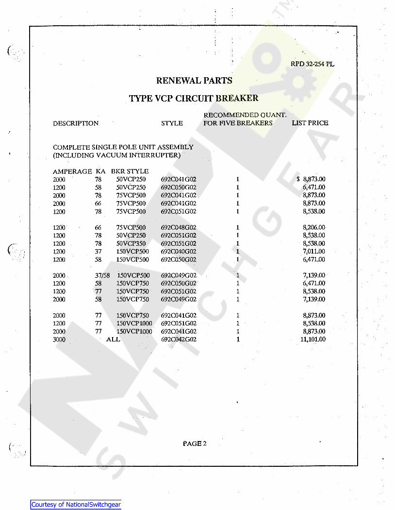
COMPLETE SINGLE POLE UNIT ASSEMBLY {INCLUDING VACUUM INTERRUPTER)
AMPERAGE KA BKRSTYLE 2000 78 50VCP250 692C041G02 1 $ 8,873.00 1200 58 50VCP250 692C050G02 1 6,471.00 2000 78 75VCP500 692C041G02 1 8,873.00 2000 66 75VCP500 692C041G02 1 8,873.00 1200 78 75VCP500 692C051G02 1 8,538.00
1200 66 75VCP500 692C048G02 1 8,206.00 1200 78 50VCP250 692C051G02 1 8,538.00
c 1200 78 SOVCP350 692C051G02 1 8,538.00
I 1200 37 150VCP500 692C040G02 1 7,011.00 1200 58 150VCP500 692C050G02 1 6,471.00
2000 37/58 150VCP500 692C049G02 1 7,139.00 1200 58 150VCP750 692C050G02 1 6,471.00 1200 77 150VCP750 692C051G02 1 8,538.00 2000 58 150VCP750 692C049G02 1 7,139.00
2000 77 150VCP750 692C041G02 1 8,873.00 1200 77 150VCP1000 692C051G02 1 8,538.00 2000 77 150VCP1000 692C041G02 1 8,873.00 3000 ALL 692C042G02 1 11,101.00
( PAGE2

( ~ RPO 32-254 PL
RENEWAL PARTS
TYPE VCP BREAKER CONTROL
Recommended Quantity List For 5 Breakers Style Number Description Price Each
48 VOLTS D. C.
1 692C091G03 Spring Charge Motor $ 633.00 1 8058A70G01 Spring Release Coil 69.00 1 8058A71G01 Shunt Trip Coil 68.00 1 765A944G03 Anti-Pump Relay 256.00 1
125 VOLTS D. C.
1 692C091G01 Spring Charge Motor 633.00 1 8058A70002 Spring Release Coil 79.00
(( 1 8058A71G02 Shunt Trip Coil 78.00 1 765A944G01 Anti-Pump Relay 537.00
250 VOLTS D. C.
1 692C091002 Spring Charge Motor 633.00 1 8058A70003 Spring Release Coil 81.00 1 8058A71003 Shunt Trip Coil 80.00 1 765A955002 Anti-Pump Relay 251.00
120 VOLTS A. C.
1 692C091001 Spring Charge Motor 633.00 1 8058A70G06 Spring Release Coil 70.00 1 8058A71002 For Capacitor Trip 78.00 1 133A595G04 Anti-Pump Relay 131.00
240 VOLTS A. C.
1 692C091002 Spring Charge Motor 633.00 1 8058A70G07 Spring Release Coil 73.00 1 8058A71003 For Capacitor Trip 80.00 1 133A595G05 Anti-Pump Relay 131.00
( J
PAGE3


