Introducing the EVLANRAO Postdoctoral Symposium, 29 April-1 May 2009
Michael P. RupenProject Scientist for WIDAR
2
The promise of the EVLA
3
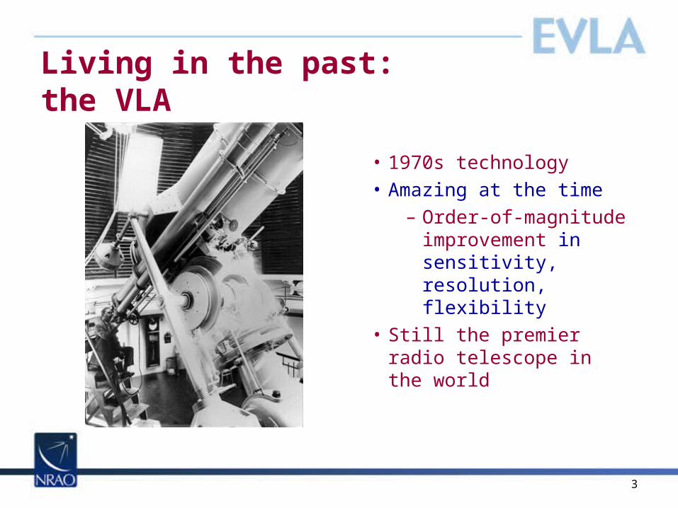
Living in the past: the VLA
• 1970s technology• Amazing at the time
– Order-of-magnitude improvement in sensitivity, resolution, flexibility
• Still the premier radio telescope in the world
4
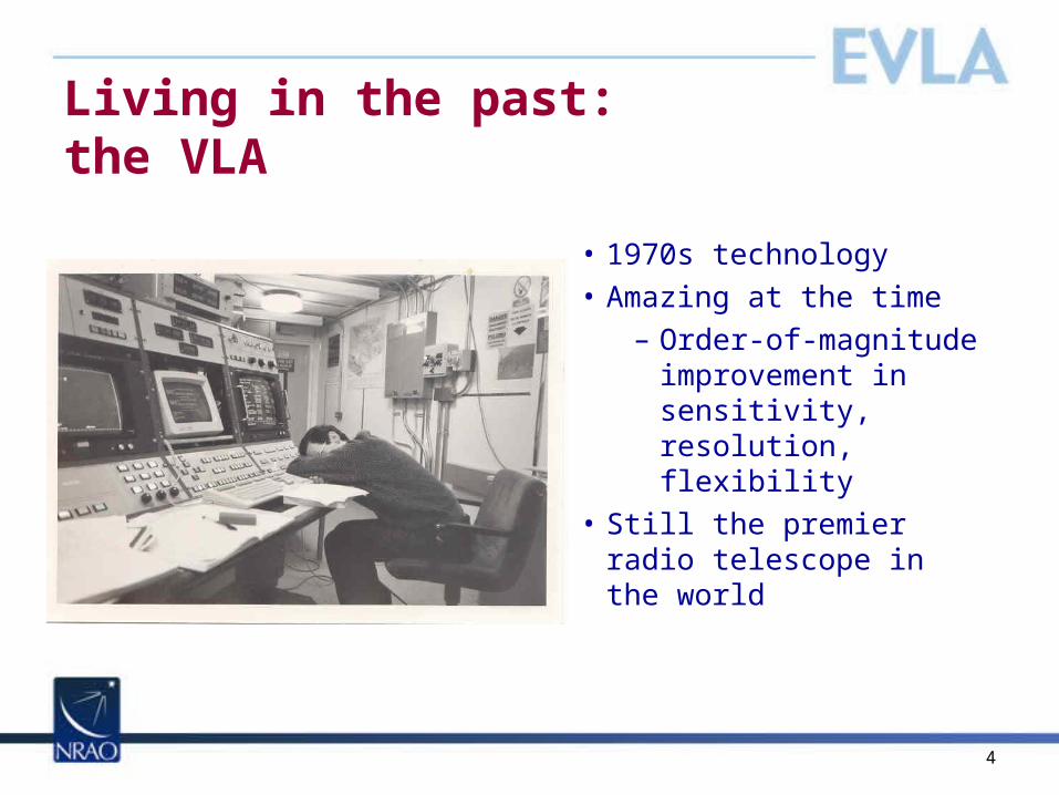
Living in the past: the VLA
• 1970s technology• Amazing at the time
– Order-of-magnitude improvement in sensitivity, resolution, flexibility
• Still the premier radio telescope in the world

5
Enter the EVLA
• Fibers• New receivers• New correlator• Bandwidth x80• Sensitivity x10
6
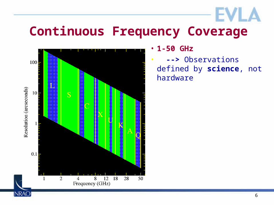
Continuous Frequency Coverage• 1-50 GHz• --> Observations defined
by science, not hardware

7
Wide Bandwidths•2:1 bandwidth ratios…with LOTS of channels
Sensitivity
1-, 12-hours Red: Current VLABlack: EVLA Goals
8
Wide Bandwidths•2:1 bandwidth ratios…with LOTS of channels
SensitivityUV-coverage
QuickTime™ and aTIFF (Uncompressed) decompressor
are needed to see this picture.
QuickTime™ and aTIFF (Uncompressed) decompressor
are needed to see this picture.
QuickTime™ and aTIFF (Uncompressed) decompressor
are needed to see this picture.
QuickTime™ and aTIFF (Uncompressed) decompressor
are needed to see this picture.
Rau, Owen, Cornwell, Eilek
1.702 GHz 1.302 - 2.102 GHz

9
Wide Bandwidths•2:1 bandwidth ratios…with LOTS of channels
SensitivityUV-coverageSpectral index & curvature
Spectral index
Spectral curvatureRau, Owen, Cornwell, Eilek
Stokes I
VLA/C1.18-1.86 GHz (16x30 mins)

10
Wide Bandwidths•2:1 bandwidth ratios…with LOTS of channels
SensitivityUV-coverageSpectral index & curvature
Polarization & rotation measures
Spectral lines & redshifts
2-41-2 4-8 8-12 12-18 18-27 27-40 40-50L S C X U K Ka Q
GHz
Sky Frequency Bands
TA*
Kaifu et al., 2004.
8 GHz
0.1 GHz
11
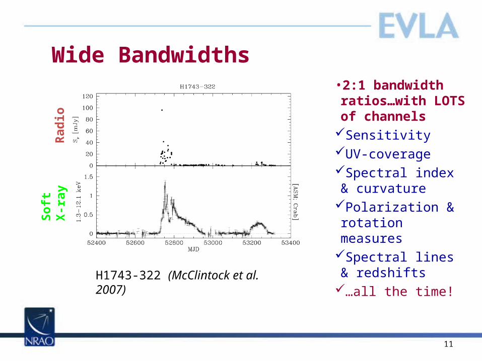
Wide Bandwidths•2:1 bandwidth ratios…with LOTS of channels
SensitivityUV-coverageSpectral index & curvature
Polarization & rotation measures
Spectral lines & redshifts
…all the time!
H1743-322 (McClintock et al. 2007)
Rad
ioS
oft
X-r
ay
12
Status & schedule

13
Current status• All fiber laid• 21 EVLA antennas now in use -- account for >70% of ant-hours• All feed horns fabricated for L, C, Ka; S and Ku underway• 9 Ka-band, 2 S-band receivers deployed
– L-band prod’n begins 2009– Ku-band prototype under development
• OMTs meet specifications (L, C, S); X-band design almost complete• LO/IF ahead of schedule• 8-bit (1 GHz) samplers installed; first 3-bit (2 GHz) due in June• Real-time software on track (migrated from Modcomps; Proposal,
ObsPrep, Scheduler, Archive Tools; WIDAR systems integration)• Post-processing software looking good (CASA; algorithms; cluster)• WIDAR correlator
– Data cables & all racks installed– final hardware ordered– 10-station, 4 subband, single pol’n WIDAR-0 fringing nicely (March 6)

14
Schedule: Growth of New Capability
Interim receivers not shown
15
Summary• Project is going well• Financial health of the project is good• Technical issues largely resolved• Project is on schedule:
– Antenna retrofits will be complete in Q3 CY2010
– Receiver installation complete in Q4 CY2012– Correlator scheduled for completion in Q1
CY2010– Software development on track to support
commissioning and early science
16
Will it work?
1717
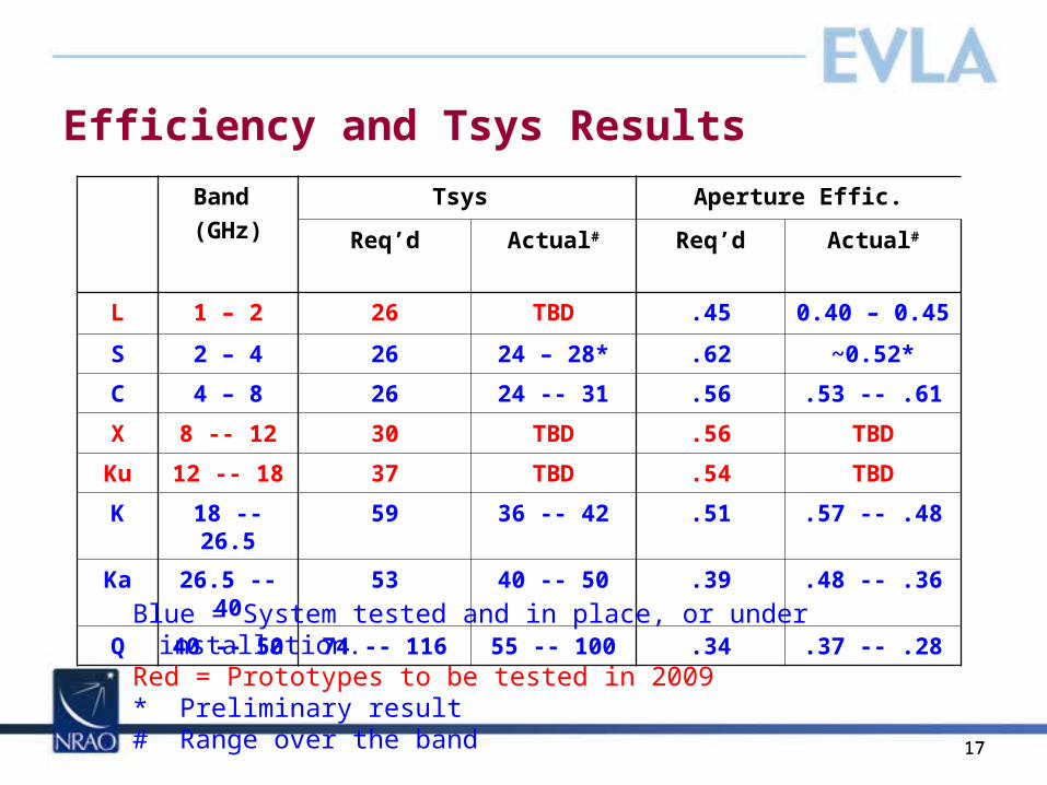
Efficiency and Tsys Results
Band (GHz)
Tsys Aperture Effic.
Req’d Actual# Req’d Actual#
L 1 – 2 26 TBD .45 0.40 – 0.45
S 2 – 4 26 24 – 28* .62 ~0.52*
C 4 – 8 26 24 -- 31 .56 .53 -- .61
X 8 -- 12 30 TBD .56 TBD
Ku 12 -- 18 37 TBD .54 TBD
K 18 -- 26.5
59 36 -- 42 .51 .57 -- .48
Ka 26.5 -- 40
53 40 -- 50 .39 .48 -- .36
Q 40 -- 50 74 -- 116 55 -- 100 .34 .37 -- .28Blue = System tested and in place, or under installation. Red = Prototypes to be tested in 2009* Preliminary result# Range over the band

1818
C and Ka Band Sensitivity Detail• Sensitivity as a function of frequency:
• Colored lines are derived via correlation coefficients • Black line with dots are from direct antenna measurements.
Ka-BandC-Band
Project Requirement
1919
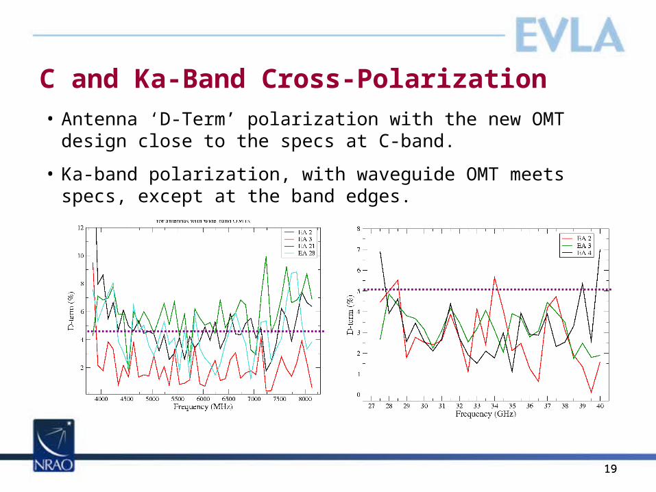
C and Ka-Band Cross-Polarization• Antenna ‘D-Term’ polarization with the new OMT design close to the
specs at C-band.
• Ka-band polarization, with waveguide OMT meets specs, except at the band edges.
2020
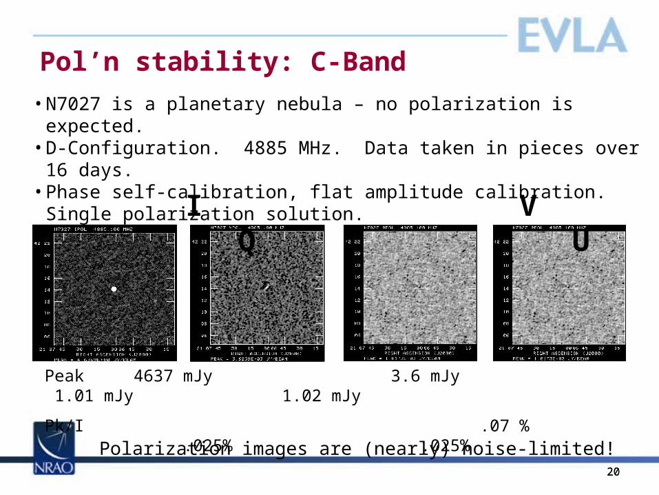
Pol’n stability: C-Band
I V Q U
• N7027 is a planetary nebula – no polarization is expected. • D-Configuration. 4885 MHz. Data taken in pieces over 16 days.• Phase self-calibration, flat amplitude calibration. Single polarization
solution.
Peak 4637 mJy 3.6 mJy 1.01 mJy 1.02 mJy
Pk/I .07 % .025% .025%
Polarization images are (nearly) noise-limited!
2121
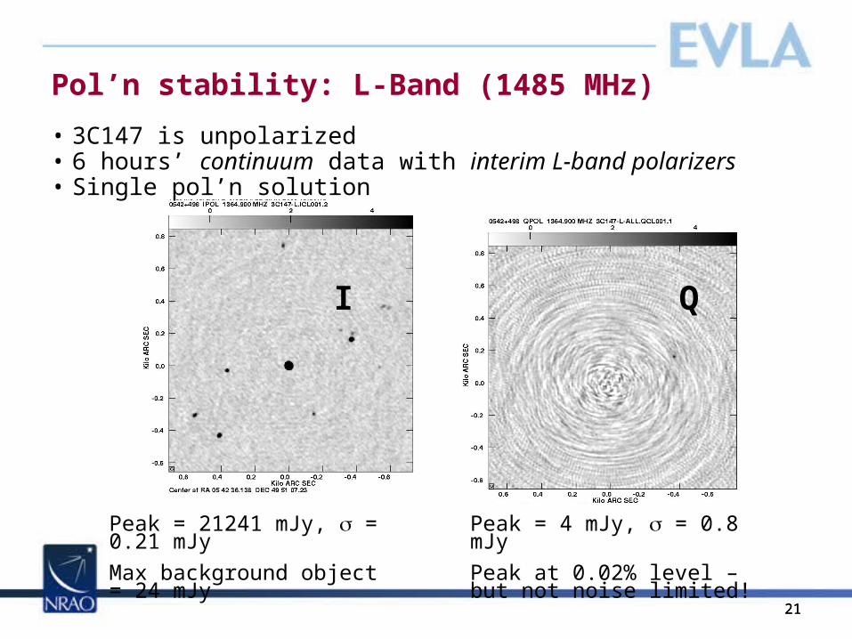
Pol’n stability: L-Band (1485 MHz)
Peak = 21241 mJy, = 0.21 mJy
Max background object = 24 mJy
Peak = 4 mJy, = 0.8 mJy
Peak at 0.02% level – but not noise limited!
I Q
• 3C147 is unpolarized• 6 hours’ continuum data with interim L-band polarizers• Single pol’n solution
2222
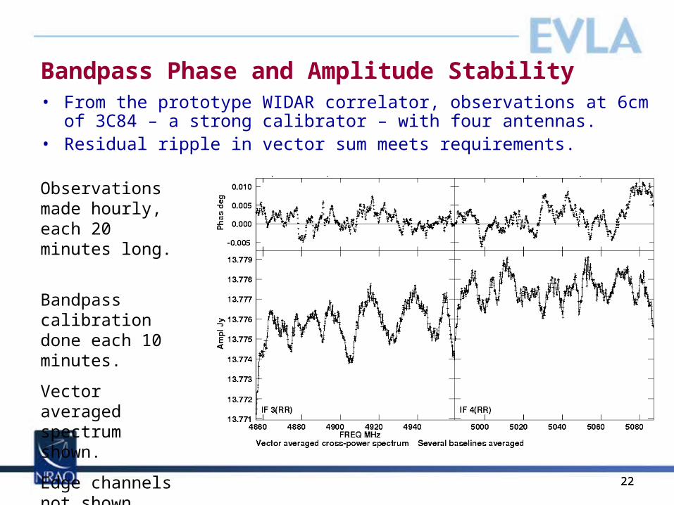
Bandpass Phase and Amplitude Stability• From the prototype WIDAR correlator, observations at 6cm of
3C84 – a strong calibrator – with four antennas. • Residual ripple in vector sum meets requirements.
Observations made hourly, each 20 minutes long.
Bandpass calibration done each 10 minutes.
Vector averaged spectrum shown.
Edge channels not shown.
23
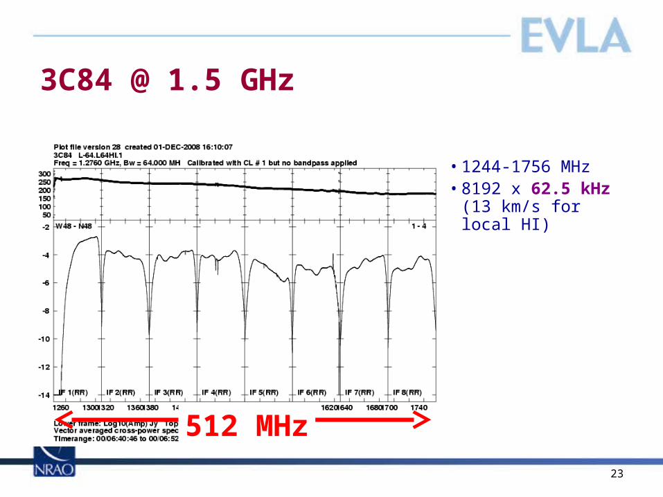
3C84 @ 1.5 GHz
• 1244-1756 MHz• 8192 x 62.5 kHz (13
km/s for local HI)
512 MHz

24
3C84 @ 1.5 GHz
• 1244-1756 MHz• 8192 x 62.5 kHz (13
km/s for local HI)
HIVLApolarizer
satellites
ABQradars
512 MHz

25
3C84 @ 1.5 GHz
• 1244-1756 MHz• 8192 x 62.5 kHz (13
km/s for local HI)
HIVLApolarizer
satellites
ABQradars
Current VLA: 6.25 MHz @ 98 kHz512 MHz
26
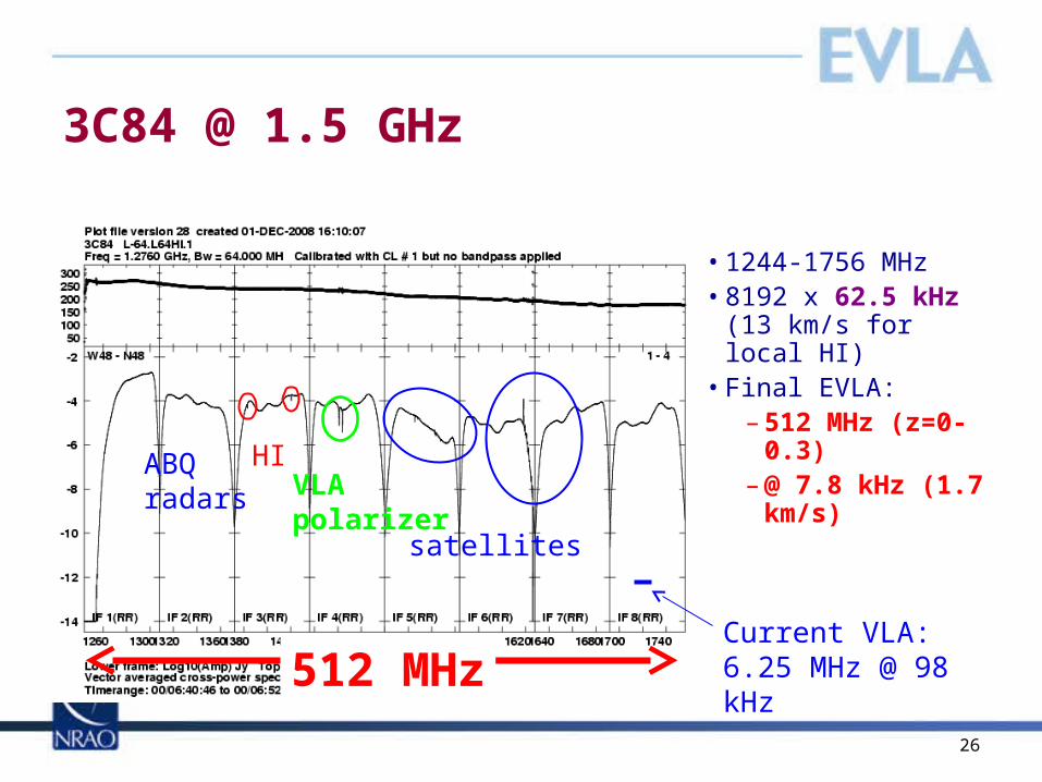
3C84 @ 1.5 GHz
• 1244-1756 MHz• 8192 x 62.5 kHz (13
km/s for local HI)• Final EVLA:
– 512 MHz (z=0-0.3)
– @ 7.8 kHz (1.7 km/s)
HIVLApolarizer
satellites
ABQradars
Current VLA: 6.25 MHz @ 98 kHz512 MHz
27
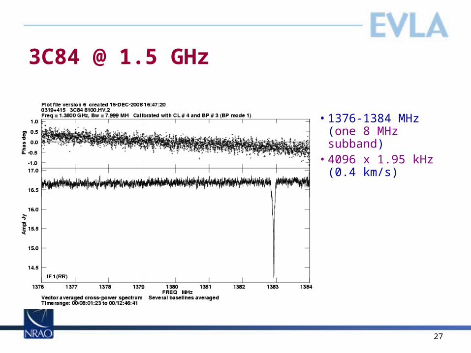
3C84 @ 1.5 GHz
• 1376-1384 MHz (one 8 MHz subband)
• 4096 x 1.95 kHz (0.4 km/s)
28
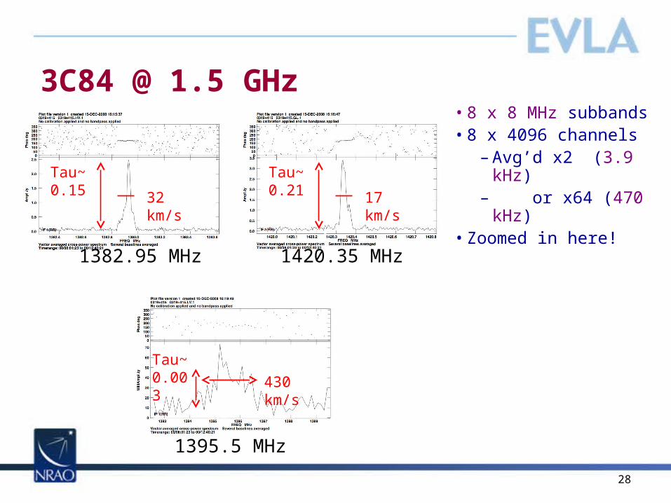
3C84 @ 1.5 GHz• 8 x 8 MHz subbands• 8 x 4096 channels
– Avg’d x2 (3.9 kHz) – or x64 (470 kHz)
• Zoomed in here!
Tau~0.15
1382.95 MHz
Tau~0.21
1420.35 MHz
32 km/s 17 km/s
Tau~0.003
1395.5 MHz
430 km/s
29
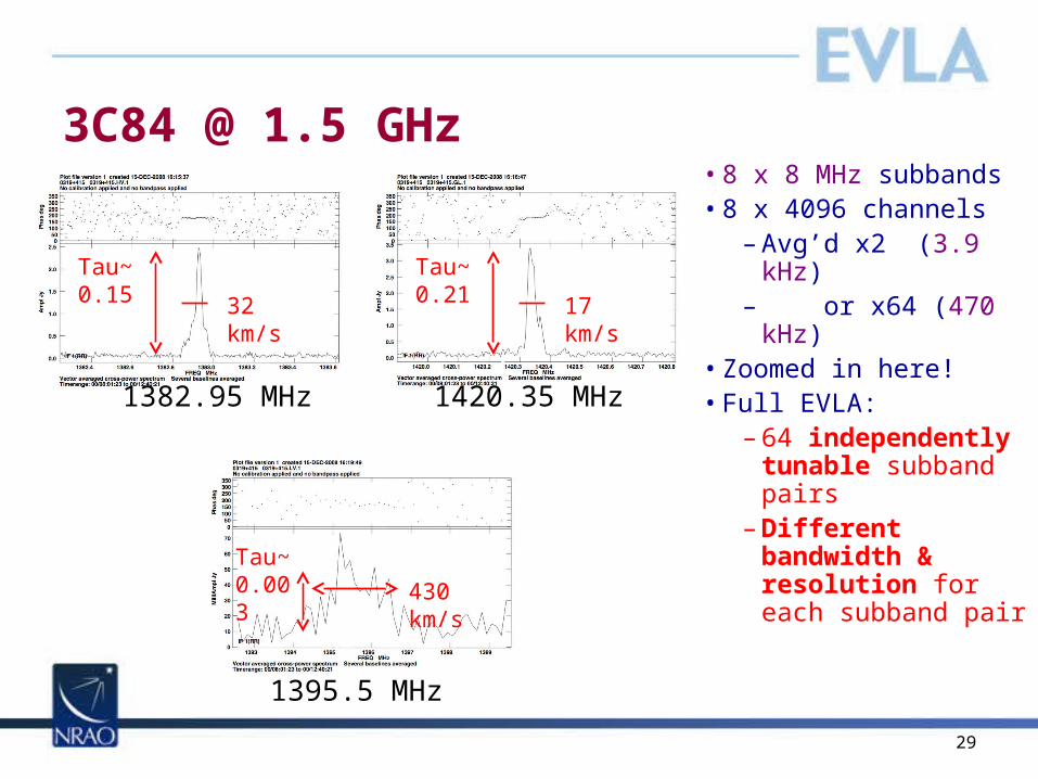
3C84 @ 1.5 GHz• 8 x 8 MHz subbands• 8 x 4096 channels
– Avg’d x2 (3.9 kHz) – or x64 (470 kHz)
• Zoomed in here!• Full EVLA:
– 64 independently tunable subband pairs
– Different bandwidth & resolution for each subband pair
Tau~0.15
1382.95 MHz
Tau~0.21
1420.35 MHz
32 km/s 17 km/s
Tau~0.003
1395.5 MHz
430 km/s
30
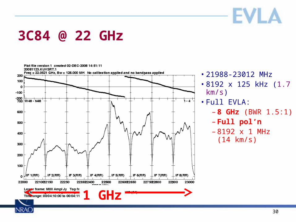
3C84 @ 22 GHz
• 21988-23012 MHz• 8192 x 125 kHz (1.7
km/s)• Full EVLA:
– 8 GHz (BWR 1.5:1)– Full pol’n– 8192 x 1 MHz
(14 km/s)
1 GHz

31
Recirculation:Orion water masers
• 64 MHz, x2 recirc.–31.25
kHz/channel• 1.4% shown here
32
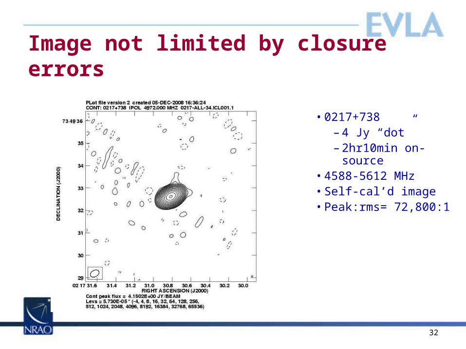
Image not limited by closure errors
• 0217+738– 4 Jy “dot”– 2hr10min on-source
• 4588-5612 MHz• Self-cal’d image• Peak:rms= 72,800:1
33
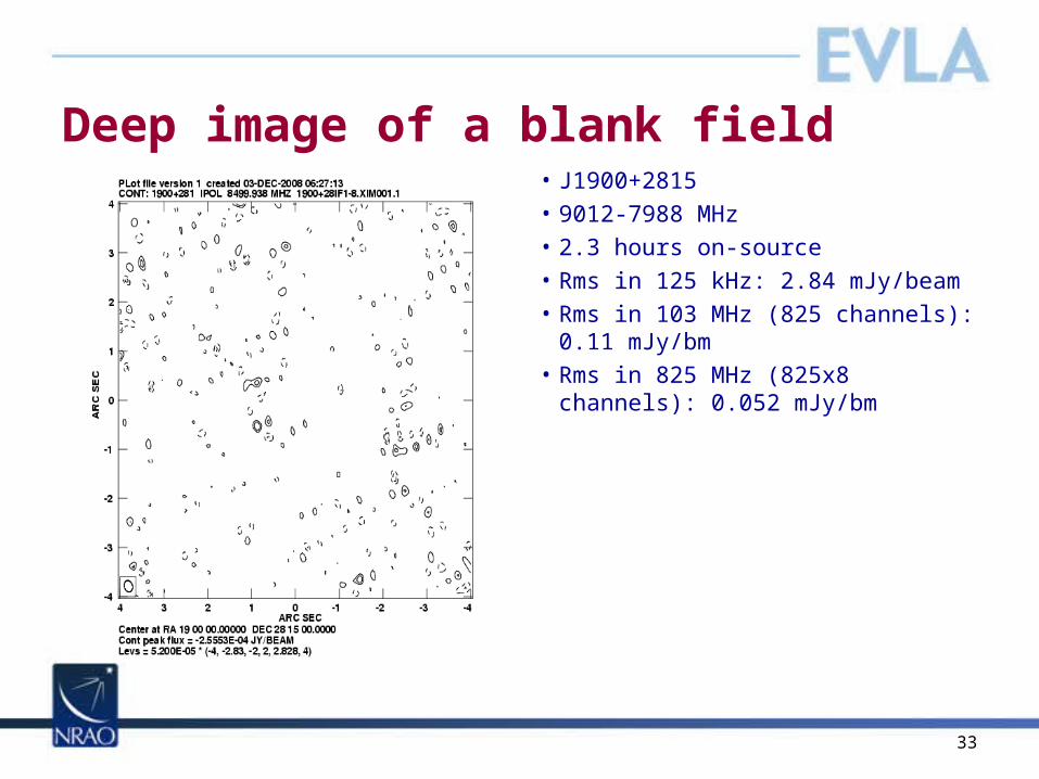
Deep image of a blank field• J1900+2815• 9012-7988 MHz• 2.3 hours on-source• Rms in 125 kHz: 2.84 mJy/beam• Rms in 103 MHz (825 channels):
0.11 mJy/bm• Rms in 825 MHz (825x8 channels):
0.052 mJy/bm
34
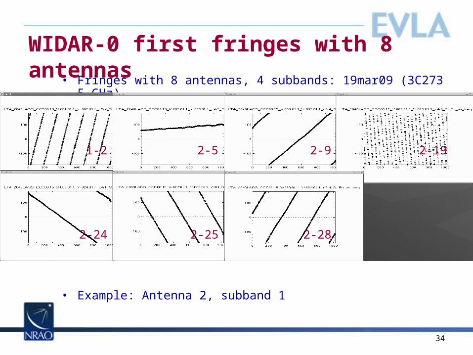
WIDAR-0 first fringes with 8 antennas• Fringes with 8 antennas, 4 subbands: 19mar09 (3C273
5 GHz)
• Example: Antenna 2, subband 1
1-2 2-5 2-9 2-19
2-24 2-25 2-28
35
Backup slides

36
RSRO capabilities: per subband, no recirculation• In the end WIDAR will provide 64 completely independent subband pairs
(independent tuning, bandwidth, pol’n products, etc.)
Sub-bandBW (MHz)
Number ofpoln. products
Number ofchannels/poln product
Channelwidth (kHz)
Channel width(kms-1 at 1 GHz)
Total velocity coverage(kms-1 at 1 GHz)
128 4 64 2000 600/(GHz) 38,400/(GHz)
64 4 64 1000 300 19,200
32 4 64 500 150 9,600
16 4 64 250 75 4,800
8 4 64 125 37.5 2,400
4 4 64 62.5 19 1,200
2 4 64 31.25 9.4 600
1 4 64 15.625 4.7 300
0.5 4 64 7.813 2.3 150
0.25 4 64 3.906 1.2 75
0.125 4 64 1.953 0.59 37.5
0.0625 4 64 0.977 0.29 18.75
0.03125 4 64 0.488 0.15 9.375
37
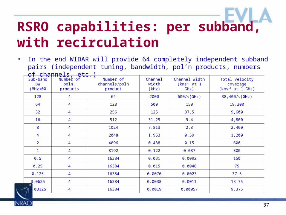
RSRO capabilities: per subband, with recirculation• In the end WIDAR will provide 64 completely independent subband pairs
(independent tuning, bandwidth, pol’n products, numbers of channels, etc.)
Sub-bandBW
(MHz)00
Number ofpoln. products
Number ofchannels/poln product
Channelwidth (kHz)
Channel width(kms-1 at 1 GHz)
Total velocity coverage(kms-1 at 1 GHz)
128 4 64 2000 600/(GHz) 38,400/(GHz)
64 4 128 500 150 19,200
32 4 256 125 37.5 9,600
16 4 512 31.25 9.4 4,800
8 4 1024 7.813 2.3 2,400
4 4 2048 1.953 0.59 1,200
2 4 4096 0.488 0.15 600
1 4 8192 0.122 0.037 300
0.5 4 16384 0.031 0.0092 150
0.25 4 16384 0.015 0.0046 75
0.125 4 16384 0.0076 0.0023 37.5
0.0625 4 16384 0.0038 0.0011 18.75
0.03125 4 16384 0.0019 0.00057 9.375

38EVLA Review March 2009 38
Correlator Rack Installation, Aug 2008
39EVLA Review March 2009 39
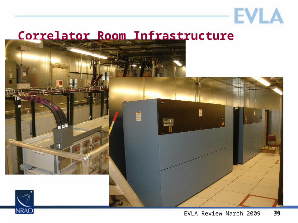
Correlator Room Infrastructure

4040
RFI: correlator linearity• WIDAR designed to provide more than 50 dB
linearity. • Early tests with the PTC are very encouraging
• Left: Scalar averaged spectrum of 3C84, showing INMARSAT
• Right: Closeup, showing astronomical signal between emissions.
• There is no sign of correlator saturation, at a level 40 dB below the peak signal strength.
41
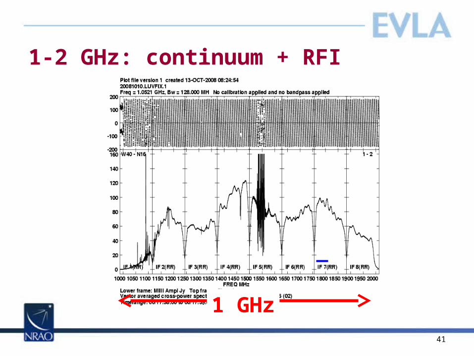
1-2 GHz: continuum + RFI
1 GHz
42
Cygnus A: MS-MFS
QuickTime™ and aTIFF (Uncompressed) decompressor
are needed to see this picture.
QuickTime™ and aTIFF (Uncompressed) decompressor
are needed to see this picture.
Rau, Owen, Cornwell, Eilek
Stokes I Spectral Index

43
Cygnus A: MS-MFS
QuickTime™ and aTIFF (Uncompressed) decompressor
are needed to see this picture.
QuickTime™ and aTIFF (Uncompressed) decompressor
are needed to see this picture.
QuickTime™ and aTIFF (Uncompressed) decompressor
are needed to see this picture.
Rau, Owen, Cornwell, Eilek
Stokes I Spectral Index
Carilli et al. 1991: VLA A+B+C+D, 1.4+4.8 GHz 1 arcsec resolution)

44
Data Rates and VolumesDriver
Target Date
% timeMax rate (Mby/s)
Mean rate (Mby/s)
Volume (Tby/yr)
Now 100 .06 .02 0.5
PTC Aug08 small 8 n/a n/a
WIDAR0 Mar09 small 20 0.1 4
256 MHz bandwidth; 1024 channels max; 1 sec min dump (OSRO)
Mar10 90 0.23 0.08 2
2 GHz bandwidth; 8096 channels max; 0.1 sec min dump (RSRO)
Mar10 10 2 0.6 2
8 GHz bandwidth; 32384 channels max; 0.1 sec min dump;
~10 antennas with 3-bit samplers(RSRO)
Jun10 10 16 5 16
8 GHz bandwidth; 1048576 channels max; 0.1 sec min dump
(RSRO)Oct10 10 75 20 60
2 GHz bandwidth; 8096 channels max; 0.1 sec min dump (OSRO)
Jun11 90 2 0.6 20
8 GHz bandwidth; 1048576 channels max; 0.1 sec min dump
(End of construction)Jan13 100 75 20 600
Early testing indicates we should have no trouble supporting these data rates


