
Introduction to High Temperature Water Heating Plants Course No: M04-030
Credit: 4 PDH
J. Paul Guyer, P.E., R.A., Fellow ASCE, Fellow AEI
Continuing Education and Development, Inc. 9 Greyridge Farm Court Stony Point, NY 10980 P: (877) 322-5800 F: (877) 322-4774 [email protected]

An Introduction to High Temperature Water Heating Plants
J. Paul Guyer, P.E., R.A. Paul Guyer is a registered mechanical engineer, civil engineer, fire protection engineer and architect with over 35 years experience in the
44240 C
El Ma
jpgu
Guyer Partnerslubhouse Drive
cero, CA 95618(530) 758-6637
design of buildings and related infrastructure. For an additional 9 years he was a principal advisor to the California Legislature on infrastructure and capital outlay issues. He is a graduate of Stanford University and has held numerous national, state and local offices with the American Society of Civil Engineers and National Society of Professional Engineers.© J. Paul Guyer 2011 1

© J. Paul Guyer 2011 2
This course is adapted from the Unified Facilities Criteria of the United States government, which is in the public domain, has unlimited distribution and is not copyrighted.

AN INTRODUCTION TO
HIGH TEMPERATURE WATER HEATING PLANTS
CONTENTS
1. GENERAL REQUIREMENTS
2. DEFINITIONS 3. TYPES OF SYSTEMS 4. SYSTEM WATER VELOCITIES 5. TYPES OF DISTRIBUTION CIRCUITS 6. HOT WATER GENERATORS 7. PRESSURIZATION 8. EXPANSION VESSELS 9. PUMPS 10. CONTROLS
© J. Paul Guyer 2011 3

AN INTRODUCTION TO HIGH TEMPERATURE WATER HEATING PLANTS
1. GENERAL REQUIREMENTS
1.1 One of the main advantages of High Temperature Water (HTW) compared to
steam systems is the smaller pipe sizes and pumps required due to the greater thermal
storage of water. Table 1 shows the influence of temperature differentials on pipe and
pump size. The minimum temperature differential recommended is 100 °F (55.5 °C).
The preferred temperature differential range is 120 to 150 °F (66.6 to 83.3 °C).
1.2 Refer to Table 2, for information on types of equipment and their application.
2. DEFINITIONS 2.1 HIGH TEMPERATURE HOT WATER (HTW) SYSTEMS. HTW systems are
designed to operate at export temperatures of 350 to 420 °F (177 to 215.5 °C).
Generally 400 °F (204.5 °C) is considered as a maximum design temperature due to
high pressures and the relative costs to achieve pressurization. The system pressure
must be at least 25 psi (172 kPa) above the saturation pressure of the HTW maximum
temperature to prevent pump cavitation and flashing of superheated water to steam. A
system operating at a maximum temperature of 350 °F (177 °C) requires at least 160
psia (1104 kPa) pressure and a system operating at a maximum temperature of 400 °F
(204.5 °C) requires a minimum pressure of 275 psia (1898 kPa). The maximum system
temperature drop from export temperature to return temperature should be 100 to 150
°F (55.5 to 83.33 °C). High temperature differentials in the HTW system can reduce
distribution piping sizes and distribution pumping costs by requiring less water flow for
the heat required. However, as the temperature differential is increased the system heat
storage capacity is reduced.
© J. Paul Guyer 2011 4

Influence of Temperature Differentials on Selection
of Pumps and Pipe Sizes for HTW Systems Temperature Difference oF 20 50 100 150 200 Discharge temperature oF 270 300 350 400 450 Return temperature oF 250 250 250 250 250 Mean temperature oF 260 275 300 375 350 Flow rate per 20 million BTU/hr (MMBH)
Lb/hr 1,000,000 400,000 200,000 133,000 100,000
Density of returning water Lbs/gal 7.86 7.86 7.86 7.86 7.86 Pump capacity GPM 2125 850 425 283 212.5 Assumed pump head Feet 100 100 100 100 100 Pump HP required HP 84.0 33.6 16.8 11.2 8.4 Assumed pump efficiency % 60 60 60 60 60 Pump size (assumed headloss 10’/100’)
IPS (inches)
8 6 4 3-1/2 3
Table 1
2.2 MEDIUM TEMPERATURE HOT WATER (MTHW) SYSTEMS. MTHW systems are
designed to operate at an export temperature between 250 and 350 °F (121 to 177 °C),
with a maximum temperature drop of 75 to 100 °F (41.7 to 55.6 °C). The system
pressure must be pressurized at least 25 psig (172.5 kPa) above the saturation
pressure to prevent pump cavitation and flashing to steam.
2.3 LOW TEMPERATURE HOT WATER (LTHW) SYSTEMS. LTHW systems are
designed to operate at an export temperature between 150 and 250 °F
(65.6 and 121 °C). Systems above 180 °F (82.2 °C) must be pressurized to prevent
pump cavitation.
3. TYPES OF SYSTEMS
3.1 RECOMMENDED
3.1.1 FORCED CIRCULATION HOT WATER GENERATORS, SEPARATE EXPANSION VESSEL, STEAM PRESSURIZATION, SINGLE PUMP. See Figure
1.
© J. Paul Guyer 2011 5

Equipment Selection for HTW Systems
Equipment Type or Use Pertinent Information HTW Generators for new plants to 500 psig and to 470 °F
Field-erected steel watertube with no steam space
Forced circulation HTW plants of small-to-large size. Generator design pressure 100 psi above that of expansion tank.
Manufacturer must prove that method of controlling circulation in tube circuits is satisfactory.
Do not permit extended surface in convection section.
Consider space requirements of generators of several different manufacturers in plant layouts.
Set safety valve 50 psig over expansion tank safety valve discharge setting.
For oil or gas firing. Limit furnace size to flame clearance.
125,000 Btu/hr For oil or gas firing. Limit furnace size to flame clearance.
95,000 Btu/hr For coal of 2,200 °F or less ash fusion temperature. Spreader stoker w/traveling grate over 25,000,000 Btu/hr output.
Boiler furnace (maximum heat input per square foot of effective radiant heating surface).
105,000 Btu/hr For coal over 2,200 °F ash fusion temperature. Spreader stoker w/traveling grate over 25,000,000 Btu/hr output.
Coal fired HTW generator grate area
See stoker selection criteria. Furnace exit gas temperature not to exceed 2200 °F or go 100 °F below the ash fusion temperature.
Air heater Tubular or regenerative When economically justified. Check safe metal temperature for sulfur content of fuel.
Economizers Not economically justified. In counter-flow designs of forced circulation boilers, convection section of boiler acts as economizer.
Sootblowers Compressed air Coal or oil HTW generators. Not required for gas fuel.
Expansion tank Design pressure to be at least 50 psig above operating pressure.
HTW pumps 350 deg F to 420 deg F maximum temperature and 1750 RPM or over
Mechanical seals with heat exchanger for cooling the water to cool face temperature of the seals to 140 °F max.
Alloy steel impellers (min. of 11% chromium).
Stainless steel shafts, sleeves and pump trim.
Ball of roller bearings oil lubricated. Stuffing box seals water cooled.
Table 2
© J. Paul Guyer 2011 6

Equipment Selection for HTW Systems
Equipment Type or Use Pertinent Information Makeup pumps, up to 15 gpm
Motor-driven reciprocating pumps.
Makeup pumps, over 15 gpm
Motor-driven centrifugal multistage or reciprocating pumps.
Pump discharge pressure shall be sufficient to deliver water to the system at 3% over the highest safety valve setting according to ASME Boiler and Pressure Vessel Code. The safety valves are generally set at not more than 6% over the maximum pressure to which the system may be subjected.
Converters Tubes and sheets of copper nickel, admiralty metal or heavy gauge steel. Tube expanded and rolled into sheets, not welded.
For secondary hot water pumping system. Temperature difference between leaving HTW of primary system and leaving hot water of secondary system should be not less than 30 oF. Use fouling factor of 0.0005 on secondary side.
Radiant panels or convectors
Heating of industrial type buildings.
Direct utilization of HTW.
Unit heaters and air handling coils
Heating and ventilating industrial type buildings. Sufficient continuous flow of HTW through coil to prevent freezing, not less than 0.5 gpm.
Select coils for circuiting, due to high water temp. drop and air stratification on air-leaving side.
Steam generators Generation of steam for heating, atomizing oil burners, and process.
Use fouling factor of 0.0001 on steam side. Temp. difference between leaving HTW and steam temp. should not be less than 30 °F to 40 °F. Vapor disengaging velocity under 3 ft/sec.
Table 2 (continued).
3.1.2 FORCED CIRCULATION HOT WATER GENERATORS, SEPARATE EXPANSION VESSEL, STEAM PRESSURIZATION, DOUBLE PUMP. See Figure 2.
At low loads, pressurization is greatly affected by increased temperatures.
3.1.3 FORCED CIRCULATION HOT WATER GENERATORS, SEPARATE EXPANSION VESSEL, INERT GAS PRESSURIZATION, SINGLE PUMP. See Figure
3.
© J. Paul Guyer 2011 7

3.1.4 FORCED CIRCULATION HOT WATER GENERATORS, SEPARATE EXPANSION VESSEL, INERT GAS PRESSURIZATION, DOUBLE PUMP. See Figure
4.
3.2 NOT RECOMMENDED
• Steam boiler, separate expansion vessel, direct-contact heat exchange of steam
and water in expansion vessel.
• Steam boiler, integral expansion vessel (boiler drum), water drawn from below
water line of drum.
4. SYSTEM WATER VELOCITIES
4.1 Central heating distribution systems should be zoned.
4.2 Irrespective of flow rates and velocities, each zone should be designed so that the
total pressure drop in the zones does not vary more than 15 percent from each other.
4.3 A minimum velocity of 2 ft/sec (0.61 m/s) in the distribution system should be
maintained to prevent stratification.
4.4 A reasonable average system water velocity is 5 ft/sec (1.52 m/s). Velocities should
be based on the median temperature of the system, provided that operating
temperatures are in excess of 350 °F (177 °C) and that the temperature drop through
the heat exchange equipment is no less than 90 °F (50 °C) nor more than 130 °F (54.4
degrees C).
© J. Paul Guyer 2011 8
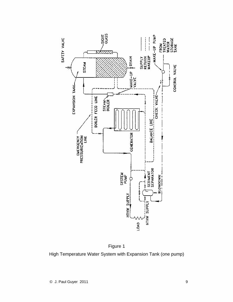
Figure 1
High Temperature Water System with Expansion Tank (one pump)
© J. Paul Guyer 2011 9

Figure 2
High Temperature Water System with Expansion Tank (two pumps)
© J. Paul Guyer 2011 10

Figure 3
High Temperature Water System with Inert Gas Expansion (one pump)
© J. Paul Guyer 2011 11

Figure 4
High Temperature Water System with Inert Gas Expansion (two pumps)
© J. Paul Guyer 2011 12

5. TYPES OF DISTRIBUTION CIRCUITS. There are many types of distribution circuits
in general use. The selection of the best system for the particular terrain and situation is
essential for satisfactory operation of a HTW plant. Extreme care must be exercised not
to design a distribution system that is difficult to operate, balance, and control.
5.1 DIRECT-SUPPLY, SINGLE-CIRCUIT. HTW is fed from the central plant directly to
the buildings to be served, passes through the heat exchange equipment, and returns to
the generators through the return main. This is a simple system to design and is the
most prevalent in use. It must be understood that the pressure at the entrance to each
connected structure is different and the sizing of control valves to give balanced flow
must be carefully analyzed. In a series circuit the decreasing supply-water temperature
from structure to structure must be accounted for in heat exchanger design. See Figure
5.
5.2 DIRECT-SUPPLY, RADIAL. This system utilizes a number of individual distribution
circuits. In such a design the length of runs tends to be shorter, and differences in
pressure at the entrances of buildings served are less. Control-valve sizing is not as
difficult as with the direct-supply single-circuit. See Figure 6.
5.3 DIRECT-SUPPLY, REVERSE-RETURN. As depicted in Figure 7, the return lines
are reversed. HTW from the central plant is fed to the connected structures. The return
mains are reversed so that the farthest buildings, which have the longest supplies, have
the shortest returns. In this manner, the system is more easily balanced and pressure
differentials at all connected structures are nearly equal.
5.4 ONE-PIPE LOOP-MAIN. A single distribution pipe is used to distribute HTW to the
connected structures. Return water from the building is fed back into the loop main. The
effect of lower temperatures at buildings farthest from the central plant must be
considered. See Figure 8.
© J. Paul Guyer 2011 13

Figure 5
Direct Supply, Single Circuit
© J. Paul Guyer 2011 14

Figure 6
Direct Supply, Radial
© J. Paul Guyer 2011 15

Figure 7
Direct Supply, Reverse Return
© J. Paul Guyer 2011 16

Figure 8
One-Pipe, Loop-Main
© J. Paul Guyer 2011 17

5.5 Primary and Secondary Distribution Systems. This is actually not a
separate system but a type of distribution that can be utilized by any of the
previously described systems. HTW carries the water economically over long
sections of pipe. At the connected structure, the HTW is converted through
heat transfer devices into low temperature water. The designer can then use
standard heat transfer devices for the buildings. See Figure 9.
6. HOT WATER GENERATORS
• Design the heating plant for not less than two generators totaling 135 to 150
percent of the heating load.
• Where practicable, the ultimate heating plant shall not require operation of more
than three simultaneously fired generators.
6.1 TYPES
• HTW generators should be of the controlled forced-circulation water-tube type,
specifically designed for HTW service.
• Fire-tube boilers and natural-circulation water-tube boilers are not recommended.
6.2 DESIGN. Generators should be designed and constructed to be suitable for the
intended HTW service and should be certified as such by the manufacturer.
6.2.1 MAXIMUM PRESSURE DROP THROUGH GENERATOR. Hot water generators
should be designed to have a maximum pressure drop through the generator of 15 psi
(103.5 kPa). Keeping the pressure drop low, usually eliminates the need for a separate
generator circulation pump, which reduces pump operating and investment costs.
© J. Paul Guyer 2011 18

Figure 9
Primary and Secondary Systems
6.2.2 STEAM SPACE. A HTW generator should be designed to have no steam space.
Inclusion of steam space of any kind within the generator can cause serious circulation
problems in the internal tube circuits and possible tube failure.
6.2.3 TUBE DESIGN. All tubes in the heat transfer zones should be designed for upflow
only. One of the inherent dangers in a HTW generator is the possibility of developing
steam bubbles. Since steam occupies much greater space than water, steam bubble
generation can cause interrupted flow in a tube or tube circuit with resultant tube failure.
When all tubes can produce only upflow, it is possible for the steam to escape from the
generator and for water flow equalization to be reestablished. Trapped steam spaces
must be avoided. Design of economizers, which are similar in construction to hot water
© J. Paul Guyer 2011 19

generators, has shown that upflow is extremely important when the temperature of the
water approaches that of saturation. Where a tube is designed for downflow of water, it
should be removed from the heat transfer zones.
6.2.4 EQUALIZATION OF FLOW THROUGH TUBE CIRCUITS. Generator design must
provide for equalization of flow through tube circuits. The water circuiting in the forced
circulation generator is a major design consideration. The circuiting must effectively
distribute the water in proportion to the heat input in any individual circuit. This is
especially important in a steam pressurized system where the water approaches
saturation temperature at the discharge of the generator. The flow of water must be
proportioned to the heat input to prevent the formation of excessive amounts of steam.
6.2.5 FURNACE DESIGN. Furnace design and burner installation should be
coordinated to ensure that there is no flame impingement on furnace tubes and walls.
Flame clearance is the major criterion when designing oil and gas combustion
chambers.
6.2.6 BLOWDOWN. Continuous blowdown of generators is a carryover from past steam
practices of eliminating sludge from mud drums. Blowdown is not required since there is
little, if any, sludge in HTW systems after the initial fill.
7. PRESSURIZATION. Pressurization is required in HTW systems in order to prevent
the formation of steam in the flow lines. This can be accomplished by exerting a
pressure on the water greater than the saturation pressure corresponding to the peak
temperature of the system. Collapse of pressurization must be avoided when system is
in operation. Sudden or complete collapse of pressurization will lead to flashing of
steam, water hammer, and similar phenomena that will set up stresses and strains that
the system is not designed to absorb. System should minimize fluctuations in system
pressure and outgoing temperature of water from generator. If wide fluctuation in
pressure is allowed, the entire system may be affected. Therefore, those systems that
allow the system pressure or outgoing temperature to rise or fall significantly are not as
© J. Paul Guyer 2011 20

satisfactory. It is also possible that pressure variation will affect the flow rate of water
through the generator, especially with one-pump systems. Reduced flow rate may result
in vapor locking and subsequent tube failure.
7.1 ACCEPTABLE PRESSURIZATION METHODS
7.1.1 SATURATED STEAM. The expansion tank is located on the suction side of the
system pump by means of an interconnecting balanced line. The steam cushion in the
expansion tank is produced by flashing HTW supply and by the operation of the external
steam boiler. The HTW heat energy source for flashing is provided by means of a small
bleed line connected at the HTW supply leaving the generator. The HTW flows to the
expansion tank to maintain the water in the tank at near generator discharge
temperature. The bleed line also serves as a boiler feedwater source to the external
steam boiler. The external steam boiler adds sufficient additional heat energy to the
HTW bleed supply to produce steam at the desired pressure in the upper portion of the
compression tank. Although the flashing water content in the lower part of the tank may
alone produce a steam cushion at saturation pressure corresponding to HTW supply
temperature, system characteristics require pressures higher than saturation. The
external boiler provides a means for maintaining system pressures above saturation
under all conditions of operation. A pressure of 25 psi (103.5 kPa) above HTW
saturation pressure is considered to be a minimum differential. One difficulty
experienced in many steam cushioned systems is that of steam flashing in generator
tubes during a cold start-up. The reason for this flashing is that until steam has been
produced, the system operates in an unpressurized condition. In this state, furnace heat
produces steam bubbles in generator tubes in spite of maintained water circulation. As
the steam bubbles form, they collect and reduce the mass of water circulated in the tube
which further accelerates flashing and reduced heat transfer. This flashing has resulted
in tube failure by overheating. The external boiler permits operating pressure to be
established prior to firing the generators. This is accomplished by starting the external
boiler and establishing the expansion tank pressure first. Once the system is at
operating pressure, there is little interchange of heat between the steam cushion and
© J. Paul Guyer 2011 21

the water in the expansion tank. Therefore, the energy requirements of the external
boiler are essentially limited to the tank surface heat losses and the generation of steam
to replace the loss of water volume experienced during the net contraction of system
water. The small magnitude of heat exchange between the tank water and steam
cushion can be better realized when one considers that the temperature of the steam
and water at their point of contact is the same. Heat transfer, therefore, depends mainly
on conduction between the upper and lower parts of the steam cushion and upper and
lower parts of the water volume. Without mechanical turbulation, the water temperature
levels will tend to stratify with the warmest (lowest density) on top and the coolest
(highest density) on the bottom. Stratification, therefore, tends to limit heat exchange in
a manner advantageous to the desired process.
7.1.2 INERT GAS. This cycle places the expansion tank on the suction side of the
system pumps by means of an interconnecting balance line. No system water flows
through the tank due to action of the pumps. The point of connection of the balance line
to the system return water piping is known as "the point of no pressure change". This
phrase is defined as indicating that the total pressure value within the piping at that
point remains the same whether the pumps are running or stopped. The "point of no
pressure change" is important to assure a condition that will prevent cavitation at the
pump impeller. Such a condition requires that a pressure be maintained well above the
boiling point of water at any temperatures likely to exist. The expansion tank is charged
with nitrogen to provide the desired system static pressure level. The charge of gas is a
fixed quantity and assuming no leakage or water absorption would remain without
adding or subtracting amounts of any load condition. The pressure within the expansion
tank, however, will not remain constant since the water level is constantly changing with
heating load change. As the heating load decreases and the return water becomes
hotter, the water expands and flows into the expansion tank raising its level. This rise in
level will compress the nitrogen to a higher pressure. In addition to these thermal
expansion pressure changes, loss in system water volume will also reduce tank level
and subsequently the pressure. Nitrogen is automatically added to maintain the
minimum system pressure. Any operating experience that shows steam formation is
© J. Paul Guyer 2011 22

taking place in the system requires a reevaluation of pressure settings. Because the
system is designed to make pressure and temperature independent of each other, the
pressure levels may be raised without affecting temperature control. Minimum pressure
should be 25 psig (103.5 kPa) above saturation pressure corresponding to supply water
temperature. It is important to note that the HTW generator burners should not be fired
until the minimum system pressure has been established. Since the HTW generator will
steam even with cold water at low pressure, tube failure is likely. When steam bubbles
begin to form in the generator tubing, they insulate the tubes and further speed up tube
burnout. Scaling of tubes is also accelerated with steam formation. Nitrogen should be
added automatically to the expansion tank through a pressure reducing valve from the
nitrogen storage tank. Do not use compressed air for pressurization because air will be
absorbed by the HTW system and consequently cause oxygen corrosion in metal
components.
7.2 UNACCEPTABLE PRESSURIZATION METHODS
7.2.1 ELEVATED TANK. This is theoretically the simplest method of pressurization.
The tank or pressurizing vessel is placed on a hillside or suitable elevation, sufficient to
provide proper hydraulic pressurization. Pressure change with volume is automatic as it
varies with the rise and fall of temperature. However, the practicability of this system
depends on suitable terrain, which is rare.
7.2.2 HYDRAULIC PUMP ARRANGEMENT. As expansion occurs, an automatic valve
releases water to a receiver. As the water contracts, a hydraulic pump is activated,
pumping water from the receiver back into the system. This system is impracticable
because small volume changes result in large pressure changes. Also, oxygen can be
introduced into the system.
7.2.3 WEIGHTED PLUNGER ARRANGEMENT. This system utilizes a separate vertical
expansion tank, a weighted plunger, and necessary seals. The plunger rises and falls
as the volume of water changes and is independent of temperature and volume
© J. Paul Guyer 2011 23

changes, maintaining a constant pressure on the system. Seal problems, however,
have been serious, and this system has not proved practicable for HTW.
7.2.4 PRESSURIZATION OF THE BOILER DRUM. Pressure is maintained in the boiler
drum at the desired pressure level with expansion of the water taken up in the rising
water line of the drum and any excess amount being relieved to a lightly pressurized
vessel. A boiler tube failure would cause immediate pressure loss, with subsequent
flashing and water hammer.
7.2.5 COMBINATION INERT GAS AND STEAM PRESSURIZATION SYSTEM. In this
system a separate expansion vessel, inert-gas tank, external heat source, feed pumps,
and necessary controls are used. As water expands, the inert gas pressurized tank
allows water to enter an externally heated spill tank under its own pressurization.
Pressure in the expansion vessel is kept constant by releasing and refeeding water into
the system. This system is complex, costly, and difficult to maintain, and is therefore
unacceptable.
7.2.6 AIR PRESSURIZATION SYSTEM. The use of air as a pressurization agent is
unacceptable since corrosive oxygen is placed into the system.
7.3 ADVANTAGES AND DISADVANTAGES OF STEAM AND INERT GAS SYSTEMS. There is little advantage of one system over the other. The choice of
pressurization is usually an economic choice rather than one of technical advantage.
7.3.1 STEAM PRESSURIZATION ADVANTAGES Lower operating pressures due to pressure-temperature relationships.
• Constant system pressure in expansion vessel.
• Controls usually fewer and less complex.
• Large amount of thermal storage in expansion vessel which aids in peak load
absorption.
© J. Paul Guyer 2011 24

7.3.2 STEAM PRESSURIZATION DISADVANTAGES
• Full flow of heated water through tank, which requires additional insulation.
• Inflexibility of expansion vessel location, which can require higher generator
rooms.
7.3.3 INERT GAS PRESSURIZATION ADVANTAGES
• Relatively cool expansion vessel expansion tank which is located so that
convection currents are restricted and system water flow will not enter the tank.
• Flexibility in locating expansion vessel.
• System pressure that can be designed for any value within recommended limits.
7.3.4 INERT GAS PRESSURIZATION DISADVANTAGES
• Higher system pressures. In order to ensure that system pressure will not drop
below saturation pressure, a safety factor must be included in design
considerations. This may necessitate the use of higher pressure rated fittings and
valves.
• Inert gas costs.
8. EXPANSION VESSELS. All systems should have dual expansion tanks to allow for
inspection and maintenance while the system is on-line.
8.1 PURPOSE. Expansion vessels absorb the expansion and contraction of system
water due to load variation and ensure, at all times, a controlled system pressure above
that corresponding to the saturation temperature. They may also act as a momentary
source of water supply in case of a system malfunction.
8.2 SIZING. Under no circumstances, where heating is the basic load, should the
expansion volume be based on cold water conditions. The expansion volume should be
based on normal design supply and return line differentials.
© J. Paul Guyer 2011 25

In a steam-pressurized system, the diameter of the expansion vessel should be 6 ft
(1.83 m) or more with an aspect ratio of 3.5 to 1.
8.3 EXPANSION VESSEL VOLUME FOR STEAM PRESSURIZED SYSTEMS. See
Figure 10.
Figure 10
Pressurized Expansion Tank Relationships
EQUATION: VT = V1 + V2 + V3
Where: VT = Total expansion vessel volume
V1 = Volume required for pressurization
V2 = Volume required for expansion and contraction
V3 = Volume required for sludge space, pump suction coverage, and
reserve capacity
© J. Paul Guyer 2011 26

8.3.1 VOLUME REQUIRED FOR PRESSURIZATION
EQUATION: V1 = 0.2 (V2 + V3)
Where: V1 = Volume required for pressurization
V2 = Volume required for expansion and contraction
V3 = Volume of sludge space based on 6 inches of depth plus the greater of the following two volumes: (a) the volume of water sufficient to cover the top of the pump intake line in the expansion vessel by 6 inches or (b) the volume needed to provide a 30 second supply of water based on combined pump capacity.
8.3.2 VOLUME REQUIRED FOR EXPANSION AND CONTRACTION These two equations show the development of this volume calculation.
EQUATION: V2 = Max Supply Water Expansion + Max Return Water Expansion
EQUATION: V2 = ([LWmaxst/ SDmaxst] – [LWminst/SDminst]) + + ([LWmaxrt / SDmaxrt ] – [LWminrt]/SD minrt]) Where: LWmaxst = lb of water at maximum supply temperature LWminst = lb of water at minimum supply temperature SDmaxst = specific density at maximum supply temperature SDminst = specific density at minimum supply temperature LWmaxrt = lb of water at maximum return temperature LWminrt = lb of water at minimum return temperature SDmaxrt = specific density at maximum return temperature SDminrt = specific density at minimum return temperature Supply water volume = the volume from the generator outlet, through the
expansion vessel, pumps, supply distribution system and heat exchange equipment
Return water volume = the volume from the heat exchanger outlet, through the return distribution system to the inlet side of the generator
8.4 DESIGN CRITERIA FOR STEAM PRESSURIZED SYSTEMS
• The vertical height of the expansion vessel above the pump shall be such that
the available net positive suction head (NPSH) is not less then 125 percent of the
required NPSH of the pump.
© J. Paul Guyer 2011 27

• Provisions must be made for expansion and anchoring of the supply and return
connections of the expansion vessel.
• The generator supply piping to the steam-pressurized vessel should slope
upward to allow venting of free gases. Cut-off valves should be located at the
beginning and end of the supply line. Each generator should have separate
supply piping to the expansion vessel.
• Generator-supply piping entering a steam-pressurized vessel should be
horizontal, with holes or slots to release water, thereby breaking up steam
bubbles and avoiding shocks.
• In the expansion vessel, the pump intake line should be located to prevent short
circuiting of the cooler return water, and a minimum of 6 inches (152 mm) below
the water line of the expansion vessel.
• Provisions should be made to prevent vortexes from forming at the inlet of the
pump intake line. This will aid in preventing cavitation in the pump.
• The expansion vessel must be located at a level above the generator outlet. An
expansion vessel located below the boiler outlet can flood, causing the steam
space to form outside the expansion vessel.
8.5 DESIGN CRITERIA FOR GAS PRESSURIZED SYSTEMS
• The pump suction line should extend a minimum of 6 inches (152 mm) above the
expansion vessel bottom to prevent sludge from entering the pump.
• The line between the expansion vessel and return main should be the same size
as the return main.
• The expansion vessel should be located on the inlet side of the generator and on
the suction side of the pump.
9. PUMPS. The three primary considerations in pump selection are suitability for HTW
services, leak-tightness and NPSH.
9.1 PUMP TYPES. Single stage centrifugal pumps are normally used to circulate HTW
through the distribution system and through the generator. The pumps selected for this
© J. Paul Guyer 2011 28

service must be designed especially for HTW in order to secure efficient, reliable
operation with a minimum of maintenance. The head characteristic of the system
circulating pumps should be flat in order to deliver nearly constant head throughout the
range of operating capacities. Generator circulating pumps shall have steep head
characteristics to accommodate the controlled circulation concept. At the same time it is
necessary that the maximum head should occur at shutoff and should fall off gradually
up to maximum capacity, suffering a decrease in pressure no more than 15 percent
below the shutoff pressure at the maximum operating capacity. Circulating pumps are
located in the return line of the system in order to maintain the highest possible positive
suction head. To further improve and guarantee efficient operation of these pumps, a
mixing connection is provided so that a portion of the system water mixes with the water
from the generator, lowering its temperature to avoid the danger of flashing at the pump
suction. The suction intake of HTW pumps must be carefully designed to avoid sudden
changes in velocity or direction which might contribute to flashing and inefficient
operation. Adequate water cooling must be provided for all pumps. Mechanical seals
are recommended.
9.2 PUMP ACCEPTANCE TESTS
• All pumps used for HTW should be tested at the factory in a range of
temperatures and corresponding saturation pressures from 250 °F (121 °C) up to
the design operating temperature of the system. The pump should be pressure
tested at one and one-half times the maximum design operating pressure of the
system. The manufacturer must certify that these tests were performed.
• The pumps should be rated in terms of pounds per minute versus head
requirements at the above mentioned pressures and temperatures.
9.3 CONSTANT VERSUS VARIABLE SPEED PUMPS
• Variable speed pumps should be used for HTW systems when economically
justifiable.
• Preferred procedure is to use three pumps, each sized for 50 percent of the load,
with one pump for stand-by.
© J. Paul Guyer 2011 29

• Where summer loads are small, an additional pump sized at 25 percent or less
may be used.
9.4 NET POSITIVE SUCTION HEAD
• The required NPSH of the pump shall not exceed 80 percent of the available
NPSH. The required NPSH is the head that the pump manufacturer must know
for correct operation of the pump. The available NPSH is the head needed to
provide this required head, in the form of either static or pressure head.
• If two or more pumps of differing head requirements are used, NPSH should be
based on the pump having the greater head requirements.
9.5 ONE-PUMP VERSUS TWO-PUMP SYSTEMS
• A one-pump system may have many pumps in the system, but they all serve the
combined purpose of delivering water to the generators as well as the system.
• A two-pump system may have many pumps in the system, but one set of pumps
delivers water to the generators, and another set of pumps delivers water to the
system.
• Hot water generators are designed for a specific flow of water through the
generator. A minimum quantity is needed to protect against tube failure and
steam generation. In a one-pump installation, this flow is usually controlled by an
automatic bypass valve which provides a uniform flow to the boiler regardless of
distribution system load variations. In a very large HTW system it may become
necessary to use a two-pump system for control of water through the generator.
The quantity of water circulated through each generator is kept more or less
constant no matter at what rate the generator is fired. There need be no
relationship during operation between the quantities of water circulated by the
system pumps and the generator circulation pumps in this arrangement except
that system flow must always be less than generator flow. With this double pump
arrangement no instruments or other equipment are needed to control the flow
through the generator because the circulation pumps have a constant capacity
and are entirely independent of the system circulation.
© J. Paul Guyer 2011 30

• Where two or more generators are installed, the generator having the greatest
pressure drop should be used in pump head calculations.
9.6 SINGLE- VERSUS MULTIPLE-STAGE PUMPS. Single-stage pumps should be
used for HTW systems. Where the head requirements exceed the capabilities of a
single-stage pump, the preferred procedure is to use single-stage booster pumps within
the distribution system.
9.7 LOCATION
• On steam-pressurized systems, pumps should be located in a central position
with respect to the generator(s) and expansion vessel. The lines connecting the
expansion vessel and pump should contain no unnecessary turns or restrictions,
and the pump location should provide the maximum NPSH possible. The pump
should be accessible for maintenance, and provisions should be made to prevent
misalignment due to external piping at elevated temperatures. Usually the pump
draws from the hottest water in the system. On some systems, a blending
mechanism is utilized to reduce the temperature to the pump to prevent flashing
or cavitation.
• On gas-pressurized systems, the expansion vessel should be located on the inlet
side of the generator and on the suction side of the pump. The pump shall be
accessible for maintenance and provisions made to prevent misalignment at
elevated temperatures.
9.8 MISCELLANEOUS
• Where separate generator pumps are used, the pump characteristics should be
in accordance with the recommendations of the generator manufacturer.
• In order to reduce the costs of meeting increased future head requirements of the
system, all pumps and casings should be designed to take the next larger
impeller size.
• The pump motor and accessories should be selected on the basis of the larger
impeller size.
© J. Paul Guyer 2011 31

10. CONTROLS
10.1 COMBUSTION CONTROLS FOR FORCED CIRCULATION GENERATORS WITH STEAM PRESSURIZED SYSTEMS
• Provide for continuous modulating control of firing, since interruption of firing may
cause a loss of pressurization in hot temperature water systems.
• For generator outputs up to 10,500,000 Btu per hour (3077 kW), use the water
outlet temperature from each boiler to control the firing rate of the generator.
• For generator outputs under 30,000,000 Btu per hour (8790 kW), provide a water
outlet temperature regulator on each generator to control the firing rate on that
generator and a master pressure controller on the expansion drum to override
the individual temperature regulators when necessary to average out the total
load among the generators carrying the load.
• For generator outputs over 30,000,000 Btu per hour (8790 kW), regulate the
firing rate of each generator by the temperature difference between outlet and
inlet water temperatures. This difference must be measured directly in order to
avoid compounding instrument errors. Provide a master pressure controller on
the expansion drum to override the individual temperature regulators when
necessary.
• As in steam boilers, draft controls shall be suited to the furnace draft
arrangement, whether pressurized or balanced.
10.2 COMBUSTION CONTROLS FOR FORCED CIRCULATION GENERATORS WITH INERT GAS-PRESSURIZED SYSTEMS. Use the same controls as on a steam-
pressurized system, except omit the master pressure regulator on the expansion tank.
10.3 WATER FLOW CONTROL FOR STEAM-PRESSURIZED HTW SYSTEMS WITH FORCED CIRCULATION GENERATORS
© J. Paul Guyer 2011 32

10.3.1 PLANTS WITH COMBINATION SYSTEM AND GENERATOR CIRCULATING PUMPS
• Measure water flow at each generator inlet so that all generator flows can be
equalized.
• Place an automatic control valve (incorporating a manual three-valve bypass) in
bypass piping between the pump discharge header and return line from the
distribution system. Use generator flow measurements to regulate the automatic
bypass control valve to assure constant design water flow through each
generator, regardless of load conditions.
• Incorporate a pressure differential switch across the pump headers or provide a
minimum flow switch in each flow meter to cut out combustion when there is
insufficient flow through a generator.
• Interlock the pump starters with combustion control to prevent generator
operation without pump operation.
• Variable speed control of pumps may be used if savings justify additional costs of
wound rotor motors and speed control equipment or variable speed clutches.
• Control flow of blending water from return line to pump suction to maintain a
constant supply water temperature to the distribution system and to prevent
cavitation of pumps due to flashing. This should be done manually for plants with
generators under 30,000,000 Btu per hour (8790 kW) and automatically for
plants with larger generators.
10.3.2 PLANTS WITH SEPARATE GENERATOR CIRCULATING PUMPS IN USE WITH SYSTEM CIRCULATING PUMPS
• Measure water flow at each generator and provide manual control of this flow so
that all generator flows can be equalized.
• Incorporate a minimum flow switch in each generator flow meter to interrupt
combustion when the flow drops below a safe value.
• Interlock the generator circulating pump starters with combustion controls of all
generators to prevent any generator operating without a pump operating.
© J. Paul Guyer 2011 33

• Generator circulating pumps should always operate at constant speed. The
system pumps may operate at variable speed only if the additional costs of
variable-speed equipment can be economically justified.
• Control the flows of blending water from the return line to system pump suctions
by a manual valve for plants with generators under 30,000,000 Btu per hour
(8790 kW) and by an automatic valve for plants with larger generators. Install a
manual throttling valve in the return line to the suction side of the generators
circulating pumps to create a pressure drop so that the control valve for the
blending water will be effective and to stop steaming conditions.
10.3.3 MAKEUP WATER FLOW CONTROL
• For small flow loss, use manual start and stop for normal makeup pumps when
expected loads are steady. If loads fluctuate widely, provide for automatic start
and stop of these pumps by float controls in the expansion tank.
• For large flow loss, use manual start and stop for emergency makeup pumps. If
there is no emergency pump, provide an electrical interlock in the system
circulating pump starters which would trip out these pumps when the low level
alarm on an expansion tank is activated.
10.3.4 AUTOMATIC ISOLATION VALVES. Equip all systems with motor-operated
valves to isolate the distribution system and assure flow through the generators in case
of a distribution line break. The supply isolation valve should close in approximately 15
seconds with the pressure sensing element located on the downstream side of the
valve. The return line isolation valve should close as soon as possible without allowing
excessive pressures to develop due to the change in velocity head into pressure head.
The pressure sensing element should be on the upstream side of the return isolation
valve. The controls shall provide for an interruption of combustion and stoppage of the
secondary (distribution) system pump operation but allow continuation of primary
(generating circulating) pump operation.
© J. Paul Guyer 2011 34

10.4 WATER FLOW CONTROL FOR STEAM PRESSURIZED HTW SYSTEMS WITH NATURAL CIRCULATION GENERATORS
• In plants with combustion system circulation and generator circulating pumps,
part of the water discharged from combination pumps is fed to steam boilers
through single element feedwater regulators. As with forced recirculation boilers,
no other automatic bypass valves are required.
• Plants with separate system circulation and generator circulating pumps, use the
same type of system circulation pumps as for the forced-circulation boiler
systems (see above). They also use the same type of feed pumps as for steam
heating plants.
• Provide continuous operation makeup pumps which feed either the boilers or
expansion tanks in response to level controls. In case of large water flow loss in
a system, provide for manual start and stop of emergency makeup pumps.
10.5 WATER FLOW CONTROL FOR INERT GAS PRESSURIZED SYSTEMS. Use the
same controls as for steam pressurized systems with forced circulation generators (see
above), but, also use automatic level controls for expansion tank.
10.6 OVERFLOW CONTROL ON STEAM PRESSURIZED EXPANSION TANKS. Use
pneumatic float valves for control of overflow levels.
11. PIPING
• Pipe connections shall be welded. Screwed joint connections except for pressure
or temperature sensing devices shall not be used. Connections to valves and
equipment shall be flanged or welded. Use metallic or spiral wound gaskets.
• Pressure piping shall conform to the requirements of ANSI B31.1, Power Piping.
• Copper and bronze materials should be avoided for HTW piping.
• Expansion should be controlled by the use of expansion loops.
© J. Paul Guyer 2011 35

12. VALVES
• All valves should be constructed of cast-steel bodies, stainless steel trim, and
packing such as Teflon.
• Bronze-trimmed valves should not be used in HTW systems.
• All valves should be capable of being repacked under operating pressures.
• Gate valves should be used only as generator isolation valves.
• Any valves other than control valves should have as low a pressure drop as
possible in order to reduce frictional losses and pumping costs.
13. SPACE AND PROCESS HEATING EQUIPMENT 13.1 DIRECT HEATING WITH HIGH TEMPERATURE WATER. This type of heating
may be achieved by:
• Unit heaters (usually high velocity type) used in buildings where the required
height for mounting still gives suitable temperatures at the floor level.
• Radiant panel heating sometimes used in large spaces where the mounting
height is greater than 10 ft from the floor level. The panels need to be spread
apart so that the radiation is uniformly directed over the spaces to be heated.
With high temperature radiant panel heating, comfort conditions can be obtained
with lower space temperatures than those required for convection heating. This
feature is especially desirable for heating areas with high ceilings such as a
warehouse or hangar.
• Forced hot air heating systems distribute air throughout the spaces to be heated.
These systems can be equipped with extended surface air heaters which use
HTW as the heating medium.
• Hospitals, laundries, kitchens and similar facilities utilize steam. HTW can be
used as the heating source provided that steam pressure beyond the saturation
pressure of the HTW plant is not required. This eliminates separate steam-
producing units, traps, and pressure-reducing valves in the primary circuit. A
sudden demand for steam can be handled with the large heat storage available
© J. Paul Guyer 2011 36

in the HTW system, but these heat exchangers will accumulate solids and must
be periodically cleaned.
13.2 INDIRECT HIGH TEMPERATURE. Heat exchangers should be designed to effect
maximum temperature drops consistent with the pressure or temperature of the medium
produced. A reduction in primary operating temperatures may effectively nullify the
operation of these heat exchangers unless they are specifically designed for varying
inlet-temperature conditions. There are two basic types of indirect heat exchangers:
• Flash or instantaneous types. These are vessels which store a small amount of
water with respect to the heating capabilities of the coil. Since no water is stored,
the fly wheel effect of heavy demands is not available, and any demand in
excess of the capabilities of the coil results in rapid temperature drops.
• Storage or inertial types. These are classified as vessels which store a large
amount of water with respect to the heating ability of the coil. The large amount
of stored water is able to meet unusually heavy demands without much difficulty.
If load requirements are periodic, standby losses may be excessive.
14. MAKEUP WATER AND WATER TREATMENT
• Makeup water is required due to small leaks, leakage around packed joints of
valves, relief valves, pump shafts, etc.
• Two makeup pumps are required, each sized for 0.5 percent of the total
distribution system flow. In case of a coal-fired generator, an additional
emergency pump rated at 5.0 percent of the distribution system flow is required.
• A treated water storage tank should be provided for emergency pumping
requirements. This tank is usually sized for approximately 20 minutes makeup
pump demand except, in coal-fired plants, the tank shall be sized for 40 minutes
of emergency flow capacity.
• A qualified water consultant should be retained on every HTW installation to
advise on water treatment for the primary and secondary water circuits.
• The initial filling of the HTW system or large water loss replacements should be
through a water treatment source other than the plant system.
© J. Paul Guyer 2011 37

• Generally deaeration is not required. Oxygen is usually removed during the initial
startup of the system.
• A demineralization unit is usually not required for a HTW system.
• A water softener sized to take care of make-up requirements for operating
conditions is recommended.
• The permanent water softener may need to be supplemented for initial fill
requirements
• Zero hardness (5 parts per million or less) and a PH of 9.3 to 9.9 with no free
oxygen should be maintained in the system at all times.
© J. Paul Guyer 2011 38


