
1
INVESTIGATING FEATURE FORMATION BY THERMOPLASTIC FORMING OF ZIRCONIUM BASED BULK METALLIC GLASS ON STAINLESS STEEL MOLDS
By
DANIEL MCINTYRE
A THESIS PRESENTED TO THE GRADUATE SCHOOL OF THE UNIVERSITY OF FLORIDA IN PARTIAL FULFILLMENT
OF THE REQUIREMENTS FOR THE DEGREE OF MASTER OF SCIENCE
UNIVERSITY OF FLORIDA
2010

2
© 2010 Daniel McIntyre

3
ACKNOWLEDGMENTS
I would like to thank my parents for constant support and dedication to me. A
special thanks goes to Dr. Gerald Bourne, my advisor for advice and guidance during
my graduate education. I would like to also thank Dr. Gregory Sawyer for his support
on this project as well as Dr. Tony Schmitz for his work.

4
TABLE OF CONTENTS page
ACKNOWLEDGMENTS .................................................................................................. 3
LIST OF FIGURES .......................................................................................................... 5
LIST OF ABBREVIATIONS ............................................................................................. 7
ABSTRACT ..................................................................................................................... 8
CHAPTER
1 INTRODUCTION .................................................................................................... 10
Background on Metallic Glass ................................................................................ 10 History .............................................................................................................. 10
Values of BMG in Production ........................................................................... 11 Challenges in Production.................................................................................. 13 Problems Associated with Crystallinity ............................................................. 14
Motivation ......................................................................................................... 16
2 PROCEDURES ...................................................................................................... 17
Alloys Used ............................................................................................................. 17 Preparation of the Alloy........................................................................................... 17
Arc Melting and Creating the Alloy ................................................................... 17 Creating the Proper Dimensions ...................................................................... 18
Steel Mold and the Load Frame .............................................................................. 19
Steel Mold ........................................................................................................ 19 Load Frame ...................................................................................................... 20
Measuring Mold Wear ............................................................................................. 24
SEM Analysis ................................................................................................... 24
Determining Crystallinity ................................................................................... 27
3 RESULTS AND DISCUSSION ............................................................................... 28
The Formation of Small Features ........................................................................... 28 Corrosion of Metallic Glass During Molding ............................................................ 30 Wear on the Molds Caused by Thermoplastic Molding ........................................... 32
4 CONCLUSION ........................................................................................................ 38
LIST OF REFERENCES ............................................................................................... 41
BIOGRAPHICAL SKETCH ............................................................................................ 43

5
LIST OF FIGURES Figure page 2-1 Copper drop mold containing a casted piece of metallic glass ........................... 18
2-2 Schematic of the molding features to be machined into a mold ......................... 19
2-3 SEM image of the mold design that was machined into a stainless steel ........... 20
2-4 Load frame setup showing platens and water cooling system ............................ 21
2-5 Schematic of the parts used with the load frame for molding ............................. 22
2-6 Cross sectional view of the molding setup .......................................................... 22
2-7 Water cooling system temperature profile during a test ...................................... 23
2-8 Water quenching temperature profile during a test ............................................. 24
2-9 SEM secondary electron image illustrating the measurement taken for circle diameter ............................................................................................................. 25
2-10 SEM secondary electron image illustrating the measurement taken for finger radius .................................................................................................................. 25
2-11 SEM secondary electron image illustrating the measurement taken for channel width...................................................................................................... 26
2-12 SEM secondary electron image illustrating the measurement taken for finger width ................................................................................................................... 26
2-13 XRD scan of Vit 1 showing a highly amorphous piece of bulk metallic glass ..... 27
2-14 XRD scan of Vit 106a showing a crystalline peak ............................................... 27
3-1 SEM secondary electron image showing machine marks replicated on a molded piece of metallic glass ............................................................................ 28
3-2 An SEM secondary electron image of a successful molding of bulk metallic glass ................................................................................................................... 29
3-3 An XRD scan of the Vit DH alloy after molding illustrating the retained amorphous structure. .......................................................................................... 30
3-4 Optical microscope image of a molded Vit 106a piece with surface corrosion ... 31
3-5 Optical microscope image demonstrating the good surface finish of the Vit DH alloy .............................................................................................................. 31

6
3-6 Circle diameter dimensional changes with respect to molding attempts of Vit DH ...................................................................................................................... 32
3-7 Finger width dimensional changes with respect to molding attempts of Vit DH .. 32
3-8 Finger radius dimensional changes with respect to molding attempts of Vit DH ...................................................................................................................... 33
3-9 Channel width dimensional changes with respect to molding attempts of Vit DH ...................................................................................................................... 33
3-10 SEM secondary electron image of a failed demolding attempt ........................... 34
3-11 SEM secondary electron image showing an angled view of a mold finger demonstrating the amount of deformation after a failed molding attempt ........... 35
3-12 SEM secondary electron image showing the rough surface after a BN aerosol was used as a lubricant ......................................................................... 36
3-13 SEM secondary electron image of the rough surface after the use of a BN aerosol lubricant ................................................................................................. 37

7
LIST OF ABBREVIATIONS
BMG Bulk metallic glass
SEM Scanning electron microscope
XRD X-Ray diffractometer
8
Abstract of Thesis Presented to the Graduate School of the University of Florida in Partial Fulfillment of the Requirements for the Degree of Master of Science
INVESTIGATING FEATURE FORMATION BY THERMOPLASTIC FORMING OF ZIRCONIUM BASED BULK METALLIC GLASS ON STAINLESS STEEL MOLDS
By
Daniel McIntyre
December 2010
Chair: Gerald Bourne Major: Materials Science and Engineering
A relatively new material, bulk metallic glass is an amorphous metal that has
mechanical properties that surpass aluminum and steel alloys. These enhanced
properties allow this material to be considered in many applications ranging from
microelectromechanical systems (MEMS) to structural uses, to electronics. Because of
the ability to be thermoplastically formed, metallic glasses can be molded into complex
shapes that conventional metals cannot achieve. The limiting factors for production for
metallic glasses at this time include their cost and the ease of forming large shapes all
while keeping a completely amorphous structure.
This thesis focuses on the formation of features on the order of 200 m that were
machined into a stainless steel mold. A total of three zirconium based metallic glass
alloys were chosen and their ability to form small intricate features on stainless steel
molds during molding was evaluated. A load frame fitted with heaters was utilized to
enable the thermoplastic forming of metallic glass alloys in a laboratory setting. The
reactivity between the metallic glass and the mold as well as the atmosphere is
observed and evaluated. Along with this, the alloys require a relatively high cooling rate
to achieve their vitreous nature. To determine crystallinity, an X-ray diffractometer was

9
used and a scanning electron microscope (SEM) was utilized to examine the formed
features. The molds were examined with an SEM to analyze the wear associated with
the molding of the alloys.

10
CHAPTER 1 INTRODUCTION
Background on Metallic Glass
History
The concept behind metallic glasses began in the 1950s when an idea was
devised through thermodynamics and kinetics that if a molten metal or metallic alloy is
cooled quickly from a liquid, the amorphous structure that was present in the liquid
would remain since the alloy would not have sufficient time to crystallize [22]. It was
suggested that an alloy, consisting of metals with different crystal structures, would aide
in slowing down the kinetics to stay amorphous upon rapid quenching from a liquid. It
was theorized that since there would be no crystalline structure, there would be no slip
planes or dislocations. This would increase the strength of the alloy and would warrant
it to be used in structural applications. In 1960, Duwez created the first metallic glass
by quenching a Au-Si liquid alloy to form an amorphous solid [1]. Following this
discovery, lead based ternary alloys were produced to allow for the liquid alloy to be
cooled slower but still achieve an amorphous structure [1]. By adding metals with
different crystal structures, melting temperatures and atomic sizes, the kinetics of the
liquid are slowed down enough to allow for the production of a metallic glass when
cooled at a fast enough rate. These alloying additions create a lower temperature
eutectic point for the system, suppressing the melting temperature [1]. During this
research, the discovery of a glass transition temperature was made in these alloys [2].
Further research was performed in the following decades that resulted with easy to form
metallic glasses and the realization that they could have far reaching engineering
implications. In the 1990s, Peker and Johnson created a quinary alloy, Vitreloy 1, which

11
consists of Zr-Ti-Cu-Ni-Be, which could be cast several centimeters in thickness, which
lead to the term bulk metallic glass [3]. The dimensions of bulk metallic glass can be
increased by either increasing the cooling rate or by slowing the kinetics, since both
resisting crystallization. Continuing research has led to alloys with increasing critical
casting thicknesses because of a decreased critical cooling rate to lock in the
amorphous structure, furthering their applications [4].
The first techniques to create metallic glass produced samples that had minimal
use for structural parts. Atomization was one of these processes. Atomization involved
melting an alloy and forcing the melt through a nozzle that separated the liquid stream
into small droplets, almost like a mist [21]. These droplets would spray into a chilled
atmosphere and would cool quickly enough to stay amorphous. What is left is a powder
of fine metallic glass particle. Another technique is splat forming [21]. This involved
imparting a liquid drop of alloy onto a chilled copper plate. The drop would ―splat‖ onto
the plate and cool quickly, leading to a metallic glass flake [21]. One other way was
called melt spinning. A chilled copper wheel was spun around and liquid metal was
poured onto the wheel [21]. The liquid would cool quickly and exit off of the wheel as a
thin sheet [21].
Values of BMG in Production
Metallic glasses can be thermoplastically formed just like a polymer. If heated to a
certain temperature, they will become viscous and will flow under a load, allowing them
to be pressed into a mold with a desired shape. The viscosity of the liquid is
temperature dependant and can vary by orders of magnitude when heated [7].
Essentially, metallic glasses are supercooled liquids, leading to this property.
Thermoplastic molding may be able to cut down on start-up costs for a company looking
12
to use metallic glasses for their part [7]. This process is inhibited by the cooling rates
necessary to resist crystallization and a proper cooling system will be necessary to
reach the critical cooling rates necessary. The cast parts can also contain defects
caused by the high velocity flow of the material into the mold cavities [5].
Another benefit is the ability to obtain net shape forming and good surface finishes
on these alloys [6]. The lack of a phase transformation from a liquid to a solid results in
no change in volume associated with the transformation [22]. The amorphous qualities
of the metallic glass lead to thermal expansion coefficient of less than 0.5% [7]. This
means that when molding a piece, it will retain its dimensions after the cooling process.
Little to no secondary machining would be needed to achieve proper dimensional
tolerances on the molded part [7]. Metallic glasses are known to replicate a molding
surface very well. They are able to replicate micrometer and nanometer features. If the
molding surface is highly polished then the molded piece will be as well. Even the
smallest machine marks can be reproduced so care has to be involved to make the
molds properly. This quality of metallic glass also allows less secondary processing to
improve the surface finish after molding since the mold dictates the surface finish.
Many mechanical properties of metallic glasses are superior to that of common
commercial metals such as steel and nickel. Metallic glasses exhibit an increased
tensile strength, ultimate tensile strength, hardness and a higher elastic limit [8]. Many
of these improved properties arise from the fact that in the amorphous structure,
dislocations do not form in addition to this, there is no slip plane so shear of the material
is inhibited, leading to increased mechanical properties [9]. These enhanced properties
make metallic glass a good choice for a part that has a load applied to it. These alloys
13
also possess increased resistance to corrosion and are electrically conductive [7,10].
Many of the alloys contain elements, including beryllium that are oxygen getters and this
leads to a resistance to oxidize at elevated temperatures [11]. Beryllium is toxic when in
a powder form so it must be decided if alloys containing this element can be used.
Challenges in Production
During molding, the alloy is subjected to elevated temperatures, which can cause
corrosion. The titanium in many alloys is insufficient to prevent corrosion by itself and it
needs to be with another oxygen getter to provide enough protection [11]. To prevent
oxidation in non-beryllium containing alloys, a controlled atmosphere must be involved.
This can be achieved by placing a chamber around the molding apparatus and
backfilling this space with an inert gas such as argon. This would eliminate the problem
of oxidation in the non-beryllium containing alloys. In a production process, the use of a
controlled atmosphere can reduce the efficiency of the process. Each molding attempt
would require a backfilling of argon and a subsequent removal of argon to extract the
part from the mold and set up a new molding attempt. This would slow the system
down and will increase the cost to produce the parts. Another reason to use a
controlled atmosphere is because as the concentration of dissolved oxygen increases in
the alloy, the amount of time to process before crystallization occurs decreases
because of the increased propensity for nucleation, leading to crystallization. [12]. With
a controlled atmosphere, more time can be taken to mold and cool the part than if the
process was performed in regular atmosphere conditions.
Metallic glass alloys need to be cooled quickly from their molding temperature in
order to achieve an amorphous structure. Each alloy has a critical cooling necessary to
keep its amorphous nature [7]. Cooling systems in the molding system can be

14
implemented to reduce the heat right after molding to ensure that the critical cooling rate
is achieved.
Mold compatibility with the alloy poses a problem for processing as well.
Reactions between the mold and the alloy can lead to problems that will make the
molded part useless. Crystallization can occur, usually on the mold surfaces first, in the
alloy when it is held too long at the molding temperature. Making all surfaces of the
mold smooth and polished can minimize this problem. At molding temperatures,
diffusion in the alloy and mold can lead to diffusion bonding between the parts,
ultimately fusing them together. Diffusion of elements from the mold into the metallic
glass can also lead to compositional changes in the metallic glass. This would
ultimately change the properties of the alloy in the diffusion layer and could also cause
crystallization. This crystallization can lead to permanent mold deformation and a
rejection of the molded part. To prevent this, tests must be performed to confirm that in
a production process, there will be no reaction between the mold and the metallic glass
that would compromise either the part or the mold.
Problems Associated with Crystallinity
Crystallinity in this alloy is unwanted and adversely affects the properties that are
associated with metallic glasses. A significant degree of crystallinity prior to molding will
result in a failed molding attempt since the alloy will not become viscous when
subjected to an elevated temperature. When unable to flow, damage to the mold will
occur when a load is applied. This introduces a problem for the surface finish of a
molded piece. Metallic glass can replicate a surface very well when molded and the
presence of crystallization on the surface inhibits this property and causes a dull finish
on the molded piece. The different crystallographic grains on the surface reflecting light

15
differently cause this dull finish. When the crystalline nature is produced after or during
molding, the mechanical, electrical and corrosion properties that are desired in the alloy
no longer exist.
The formation of a crystalline structure forms in the alloy when three things
happen either individually or together. The first is when the alloy is heated to above its
crystallization temperature. This temperature is determined using a DSC and can be
avoided during molding [14,15]. Above the crystallization temperature, the kinetics of
the alloy are fast enough to enable nucleation and growth or crystals upon cooling [16].
The second way is to cool the alloy at a slower rate than the critical cooling rate. A slow
rate will allow atomic movements and will result in nucleation of crystals. A slow cooling
rate is an issue during the drop molding process of the alloy. The drop mold and hearth
are two separate pieces and do not form a good contact to one another. This results in
a poor heat transfer between the two pieces. When the molten alloy drops into the
mold, the cooling rate is thus reduced and can be slow enough to cause crystallization
in parts of the alloy, usually towards the top of the drop mold where the most heat is
contained. Each alloy of metallic glass has different crystallization temperatures and
critical cooling rates. To avoid crystallization of the alloy, this temperature must not be
exceeded. The third way to cause crystallinity in these alloys is to allow oxygen into the
composition. This can occur if the metal is at an elevated temperature in ambient
atmosphere, which occurs during molding. The higher the concentration of oxygen, the
less time available to work and mold the metal before crystallization occurs. The
presence of oxygen at high temperatures can lead to oxidation of the piece. Oxidation
ruins the surface finish and thus makes the use of metallic glass less desirable.

16
The choice of alloy is important since oxygen can be absorbed into the alloy at
high temperatures. Some metallic glass alloys contain beryllium, which helps to reduce
this problem. Beryllium is an oxygen getter so when the alloy is subjected to elevated
temperature, the oxygen will preferentially be attracted to the beryllium and will prevent
a shortened processing time as well as surface corrosion. Unfortunately, beryllium is a
toxic material so it is undesirable to choose a beryllium containing alloy for use in a
product that would be used by people. Most beryllium containing alloys have a lower
critical cooling rate than an alloy deficient of beryllium. Because of this, keeping an
alloy amorphous after molding is more difficult and requires the use of a quench tank
rather than a platen cooling system that is attached to the load frame. In a mass
production based operation, this issue would need to be addressed with a better system
to cool the alloy post-molding.
Motivation
This research will focus on forming features approximately 200 m in size in two
beryllium containing alloys and one non-beryllium containing alloy and investigating
whether molding and demolding can be achieved with a stainless steel mold for
production processes. The features machined in the mold will be measured after each
molding attempt to record deviations in dimensions. Reactions of the alloys, during
molding, with the mold and the atmosphere will be also evaluated to determine if they
affect the molding process.

17
CHAPTER 2 PROCEDURES
Alloys Used
Three zirconium based alloys were chosen for the molding of bulk features. The
alloys were chosen based on their mechanical properties as well as on the critical
cooling rates and crystallization temperature. The alloys were Vit 1 (Zr41.2Be22.5
Ti13.8Cu12.5Ni10), Vit DH (Zr35Ti30Be27.5Cu7.5) and Vit 106a (Zr58.5Cu15.6Ni12.8Al10.3Nb2.8)
[7,23]. In order to keep an amorphous structure in the these alloys, the part must be
rapidly cooled from the liquid at a rate from 1 C to 10 C per second, deemed the
critical cooling rate. The critical cooling rates of these alloys are low enough so that an
amorphous structure can be obtained simply by quenching in water directly after
molding.
Preparation of the Alloy
Arc Melting and Creating the Alloy
The alloys were obtained and produced from outside sources. Each alloy was
created from high purity powders to reduce impurities. A bell jar arc furnace was used
to melt the powders. The chamber of the arc melter was backfilled with argon to
minimize the amount of oxygen present prior to melting the alloy. A titanium getter was
struck with an arc and melted prior to melting the alloy to remove any residual oxygen in
the chamber that would compromise the alloy. A copper water chilled hearth was used
to cool the molten alloy as quickly as possible to prevent crystallization. The final alloy
was in the shape of a small button that is a result of the hemispheres machined into the
hearth to allow the pooling and consolidation of the melt.

18
Creating the Proper Dimensions
A low speed diamond saw was used to section the arc melted button of metallic
glass into 3.5 to 5.5 g pieces. A copper drop mold, Figure 2-1, has a channel for
casting to fit that amount of material in the mold.
Figure 2-1. Copper drop mold containing a casted piece of metallic glass [7]
Two drop molds were used to melt the alloy into the desired shape. The first drop
mold had the melted alloy sitting above the water chilled hearth, separated by the drop
molds copper lining about 5 mm thick as seen in Figure 2-1 above. The second drop
mold had a through cut that allowed the melted alloy to directly touch the hearth during
cooling. The second drop mold was created for Vit 106a, which required a faster
cooling rate to ensure an amorphous structure. Similar to before, the chamber of the
arc melter was backfilled with argon 3 times and a titanium getter was used to ensure
the oxygen concentration in the chamber was minimal. To ensure a high rate of
cooling, the copper water chilled hearth was used.

19
Steel Mold and the Load Frame
Steel Mold
The material chosen for the mold was a 316 stainless steel. Stainless steel was
chosen for its relatively cheap cost and corrosion resistance. The mold was a cylinder
25mm in diameter and 6.3 mm thick made from stainless steel. On one face of the
mold, a design was machined into it as seen in Figure 2-2 and 2-3. The design was
simply four fingers, each with a channel and hemisphere machined into them.
Figure 2-2. Schematic of the molding features to be machined into a mold
5 mm SQ

20
Figure 2-3. SEM image of the mold design that was machined into a stainless steel
Load Frame
The load frame as seen in Figure 2-4 was capable of applying a maximum load of
5000 N. The load frame was first build by Jeff Bardt for his research to develop a
similar process for silicon molds [7]. The top and bottom platens contain cartridge
heaters inside of them and the whole setup is demonstrated in Figure 2-5. The heaters
provide adequate heating to the platens, which then heat metallic glass into a viscous
enough state to be pressed into a mold. The time necessary to bring the platens and

21
molding pieces to a proper operating temperature is approximately 60 seconds. This
relatively quick time to heat up reduced the opportunity for both corrosion and any
reactivity that can exist between any of the molding materials and the metallic glass. A
load of 2000 N was applied to the mold at the designated temperature of around 350° C,
depending on the alloys glass transition temperature. The amount of pressure was load
controlled so when the metallic glass alloy starts to flow, a constant pressure was
applied, which allows a uniform flow of the alloy into the mold [7]. There were 4 parts
accompanying the mold that were used to ensure proper alignment and pressure from
the load frame on the metallic glass and the mold as seen in a simplified Figure 2-6.
Essentially, the mold and metallic glass were placed onto a platen and a ram directed
the force down onto these pieces for molding.
Figure 2-4. Load frame setup showing platens and water cooling system [7]

22
Figure 2-5. Schematic of the parts used with the load frame for molding [7]
Figure 2-6. Cross sectional view of the molding setup [7]
F(t)
Mold pocket
Ram
BMG Mold
Heating/cooling base for T(t)

23
A water cooling system was implemented into the top and bottom platen to provide
sufficient cooling to keep the alloy amorphous. The cooling system starts when the load
is removed after the molding has finished. If a faster cooling rate than can be achieved
by the system is needed, the mold and accessories can be quickly dropped into a water
filled quench tank. The cooling rate for the quench tank is much greater than the
cooling system, which is seen in comparing Figure 2-7 and 2-8. The cooling system
results in a maximum cooling rate of approximately 0.87 C/sec. The water quench rate
is essentially instantaneous and thus cannot be quantified.
Water Cooling System Temperature Profile
0
50
100
150
200
250
300
350
400
450
1 91 181 271 361 451 541 631 721 811 901 991 1081 1171 1261 1351 1441 1531 1621 1711 1801 1891
Tiem (s)
Tem
peratu
re (
C)
Figure 2-7. Water cooling system temperature profile during a test

24
Water Quenching Temperature Profile
0
50
100
150
200
250
300
350
400
1 8 15 22 29 36 43 50 57 64 71 78 85 92 99 106 113 120 127 134 141 148 155 162 169 176 183 190
Time (s)
Tem
peratu
re (
C)
Figure 2-8. Water quenching temperature profile during a test
Measuring Mold Wear
SEM Analysis
A scanning electron microscope (SEM) was used to obtain secondary electron
images of the mold that were then analyzed and measured to determine any changes of
dimension. The SEM was operated at 30kV at a pressure of less than 5e-5 mbar. The
mold was analyzed prior to molding and repeatable measurements were recorded.
These measurements were taken after each successive molding of the alloy. The
amount of deformation caused by molding of Vit DH was analyzed for this process and
a total of four measurements were taken to measure deformation and they are
represented as a yellow line in Figures 2-9 to 2-12.

25
Figure 2-9. SEM secondary electron image illustrating the measurement taken for circle diameter
Figure 2-10. SEM secondary electron image illustrating the measurement taken for finger radius

26
Figure 2-11. SEM secondary electron image illustrating the measurement taken for channel width
Figure 2-12. SEM secondary electron image illustrating the measurement taken for finger width

27
Determining Crystallinity
To ensure the alloy used in the molding process was completely amorphous, the
samples were scanned in a powder X-Ray diffractometer (XRD) before and after the
molding process as shown in Figures 2-13. In circumstances that show post-molding
crystallinity like in Figure 2-14, the temperature used during molding can be altered to
ensure an optimum molding temperature for that specific alloy.
Vit 1 XRD Scan
0
50
100
150
200
250
20 25 30 35 40 45 50
2 Theta
Coun
ts
Figure 2-13. XRD scan of Vit 1 showing a highly amorphous piece of bulk metallic glass
Vit 106a XRD Scan
0
50
100
150
200
250
20 25 30 35 40 45 50 55 60
2 Theta
Coun
ts
Figure 2-14. XRD scan of Vit 106a showing a crystalline peak
28
CHAPTER 3 RESULTS AND DISCUSSION
The Formation of Small Features
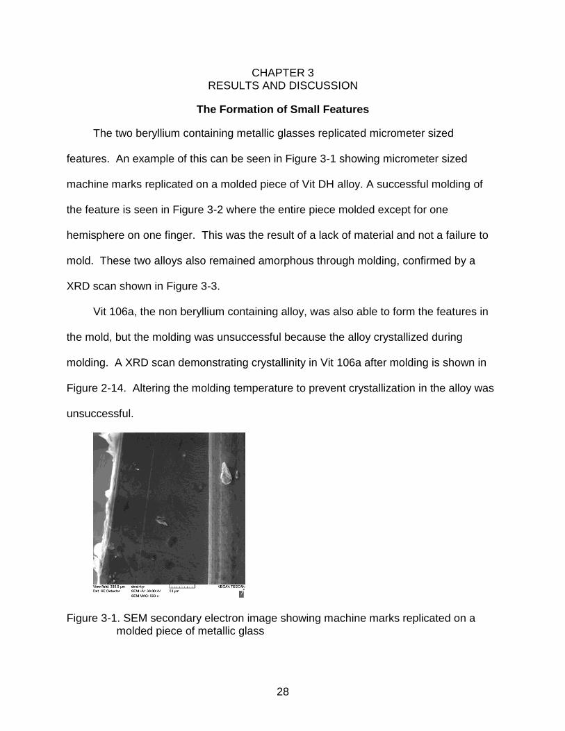
The two beryllium containing metallic glasses replicated micrometer sized
features. An example of this can be seen in Figure 3-1 showing micrometer sized
machine marks replicated on a molded piece of Vit DH alloy. A successful molding of
the feature is seen in Figure 3-2 where the entire piece molded except for one
hemisphere on one finger. This was the result of a lack of material and not a failure to
mold. These two alloys also remained amorphous through molding, confirmed by a
XRD scan shown in Figure 3-3.
Vit 106a, the non beryllium containing alloy, was also able to form the features in
the mold, but the molding was unsuccessful because the alloy crystallized during
molding. A XRD scan demonstrating crystallinity in Vit 106a after molding is shown in
Figure 2-14. Altering the molding temperature to prevent crystallization in the alloy was
unsuccessful.
Figure 3-1. SEM secondary electron image showing machine marks replicated on a molded piece of metallic glass

29
Figure 3-2. An SEM secondary electron image of a successful molding of bulk metallic glass. The top finger not molding a hemisphere was a result of a lack of material and not a failed molding

30
Figure 3-3. An XRD scan of the Vit DH alloy after molding illustrating the retained amorphous structure.
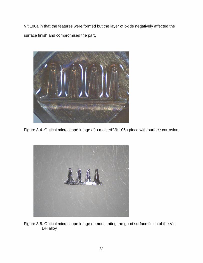
Corrosion of Metallic Glass During Molding
The alloys that contained beryllium were not susceptible to oxidation during
molding. Vit 106a formed a visible surface oxide during molding. An example of
surface oxidation can be seen in the optical microscope image in Figure 3-4, which was
a molded sample of Vit 106a. As a comparison, Figure 3-5 is a molded sample of Vit
DH, which shows a polished metallic surface. The molding was partially successful for
31
Vit 106a in that the features were formed but the layer of oxide negatively affected the
surface finish and compromised the part.
Figure 3-4. Optical microscope image of a molded Vit 106a piece with surface corrosion
Figure 3-5. Optical microscope image demonstrating the good surface finish of the Vit DH alloy

32
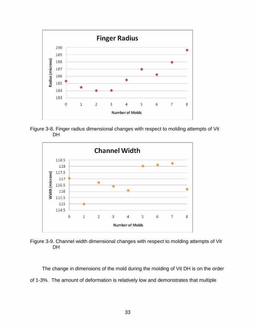
Wear on the Molds Caused by Thermoplastic Molding
The stresses and strains associated with molding the metallic glass were not
sufficient to cause significant changes in the dimensions of the molds even after
multiple molding attempts with VIT DH, as seen in Figure 3-6 to 3-9.
Figure 3-6. Circle diameter dimensional changes with respect to molding attempts of Vit DH
Figure 3-7. Finger width dimensional changes with respect to molding attempts of Vit DH
33
Figure 3-8. Finger radius dimensional changes with respect to molding attempts of Vit DH
Figure 3-9. Channel width dimensional changes with respect to molding attempts of Vit DH
The change in dimensions of the mold during the molding of Vit DH is on the order
of 1-3%. The amount of deformation is relatively low and demonstrates that multiple
34
molding attempts can be performed before the mold is determined to be unusable
because of dimensional considerations.
The water-cooling system on the load frame was tested with a sample of Vit DH to
determine if the cooling rate was sufficient to prevent crystallization. The XRD scan
after molding showed a definite crystalline peak, signifying that the water cooling system
does not cool the metallic glass faster than the critical cooling rate for that alloy.
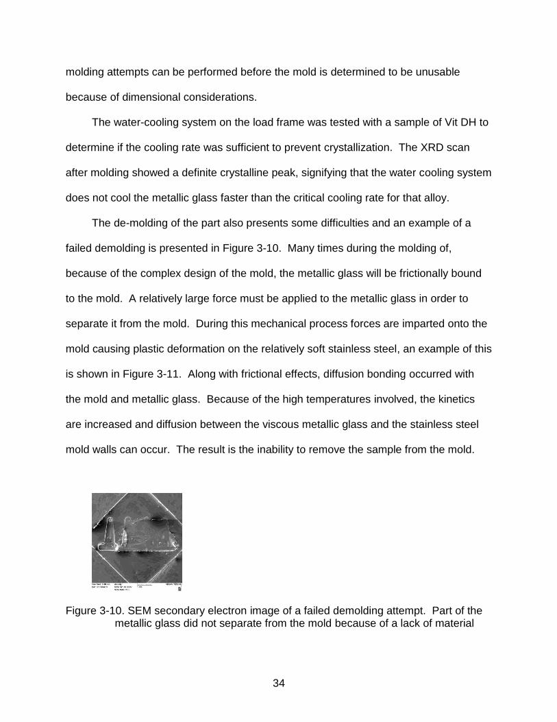
The de-molding of the part also presents some difficulties and an example of a
failed demolding is presented in Figure 3-10. Many times during the molding of,
because of the complex design of the mold, the metallic glass will be frictionally bound
to the mold. A relatively large force must be applied to the metallic glass in order to
separate it from the mold. During this mechanical process forces are imparted onto the
mold causing plastic deformation on the relatively soft stainless steel, an example of this
is shown in Figure 3-11. Along with frictional effects, diffusion bonding occurred with
the mold and metallic glass. Because of the high temperatures involved, the kinetics
are increased and diffusion between the viscous metallic glass and the stainless steel
mold walls can occur. The result is the inability to remove the sample from the mold.
Figure 3-10. SEM secondary electron image of a failed demolding attempt. Part of the metallic glass did not separate from the mold because of a lack of material

35
Figure 3-11. SEM secondary electron image showing an angled view of a mold finger demonstrating the amount of deformation after a failed molding attempt
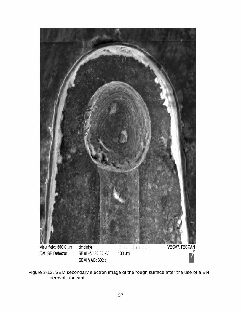
Lubrication was suggested to prevent difficulties in the de-molding process. The
lubrication used was a boron nitride aerosol. Characterization of the BN particles found
that particles as large as 10 m in diameter existed. The surface finish on the part was
negatively influenced by the lubrication because it interfered with the ability of the
metallic glass to replicate the surface of the mold, which is visible in Figures 3-12 and 3-
13.

36
Figure 3-12. SEM secondary electron image showing the rough surface after a BN aerosol was used as a lubricant
37
Figure 3-13. SEM secondary electron image of the rough surface after the use of a BN aerosol lubricant
38
CHAPTER 4 CONCLUSION
Metallic glasses provide enhanced performance over many of their metallic
counterparts such as steel and aluminum. While metallic glass alloys are relatively
expensive and more difficult to fabricate, they are able to be formed into smaller parts.
Compared to common load bearing metals such as steel and aluminum, metallic
glasses generally have a higher yield strength, ultimate tensile strength, a lower
Young’s modulus and higher elongation. Parts as small as MEMS can be created with
metallic glasses that provide improved mechanical properties over the mechanical
fatigue limitations of the other materials used in the devices [17,18]. The corrosion
properties of these alloys trump common metals as well. The oxygen getters common
in the composition of many metallic glasses protect against oxidation of the alloy.
Metallic glasses also possess the ability to be thermoplastically formed using
common procedures of vacuum die and suction casting [5,20]. At elevated
temperatures, these alloys flow viscously and this property allows the alloy to be
processed in a similar manner to polymers that have been made in this manner for
many years. Because of the viscous flow of the material, the molding of complex parts
can be achieved. Such parts would be too hard or expensive to produce with common
processing techniques for crystalline metals. In addition, metallic glass alloys inherently
have a relatively low coefficient of thermal expansion and do not change phase, so
there is no change in volume during molding. Because of this, net shape parts can be
molded in one step and will not have to be machined down to proper dimensional
tolerances. This means a higher efficiency and lower cost for production. Furthermore,
these alloys are able to replicate features and surfaces very well. While molding, if the

39
design in the mold is highly polished then the metallic glass surface will be as well,
reducing any secondary finishing.
The molding of the three zirconium based metallic glass alloys in ambient
atmosphere using 316 stainless steel molds was investigated to determine the feasibility
in a production process. Mold part feature reproduction and mold wear was monitored
and characterized for 8 molding attempts with Vit DH, a beryllium containing alloy.
The features that were molded with Vit 1 and Vit DH showed ease of release,
reproducibility and minimal mold wear. Molding attempts with Vit 106a, a beryllium free
alloy, were unsuccessful due to crystallization and oxidation of the sample. Molding of
the two beryllium containing alloys was successfully demonstrated in an ambient
atmosphere while molding attempts with the beryllium alloy was unsuccessful.
The amount of wear from the molding process on 316 stainless steel molds was
not a significant issue when molding Vit DH. Stainless steel is a viable mold material for
the thermoplastic forming of metallic glass. When the proper molding temperatures are
used, the amount of wear on the mold after each molding attempt was between 1% and
3%. This is suitable for a large production run where the most uses out of a single mold
is needed for the cost efficiency. Another benefit to metallic glass processing is the fact
that simple alloys such as stainless steel or nickel can be used as mold materials,
making the process even more cost efficient. To reduce the overall wear on the mold
and extend its lifetime, lubrication can be used to aid in the de-molding process. The
issues with using lubrication are surface finish and reactivity with the alloy. While
molding on the micron scale, the smallest particle of contamination from the lubrication
can cause adverse affects on the surface finish of the part. Elements in the alloy can
40
also react with certain elements in the lubrication and can create unwanted phases that
can negatively affect the properties of the alloy.
Future work on these alloys includes research into non-beryllium containing alloys
that do not oxidize under elevated temperatures and have a large processing window.
This would eliminate the need for a controlled atmosphere around the molding
apparatus and will cut costs to produce parts in a production run. The use of a
controlled atmosphere will also be examined. Research into the causes of
crystallization and oxidation in beryllium free alloys will be investigated to explore a
solution. The load frame will be setup to allow for an argon containment unit around the
platens and mold to eliminate oxidation. A process to automate the molding and de-
molding, all while allowing the use of the controlled atmosphere chamber will be
evaluated. These processes will be further researched as to whether they influence the
amount of mold wear caused by molding and de-molding of the part.

41
LIST OF REFERENCES
[1] R. DeHoff. Thermodynamics in Materials Science. Second Edition. Taylor & Francis Group, LLC. (2006) [2] W. Klement, R.H. Willens, P. Duwez, Non-crystalline structure in solidified gold-silicon alloys. Nature. 869–870, 187 (1960) [3] H.S. Chen, D. Turnbull, Formation, stability and structure of palladium-silicon based alloy glasses. Acta Metall. 1021-1031, 17 (1969) [4] A. Peker, W.L. Johnson, A highly processable metallic glass–Zr41.2Ti13.8Cu12.5Ni10.0Be22.5. Appl Phys Lett. 2342–2344, 63 (1993) [5] J. Loffler, Review-Bulk metallic glasses. Intermetallics. 529-540, 11 (2003) [6] S. Kalpakjian, Manufacturing Processes For Engineering Materials, Fifth Edition, Pearson Education, Inc. p. 125, 236, 671 (2008) [7] J. Bardt, G. Bourne, T. Schmitz, J. Ziegert, W.G. Sawyer, Micromolding three-dimensional amorphous metal structures. J. Mater. Res. Vol. 22, No. 2 (2007) [8] A. Wiest, J. Harmon, M. Demetriou, R. Conner, W. Johnson, Injection molding metallic glass. Scripta Materialia 160-163, 60 (2009) [9] M. Macht, T. Zumkley, S. Suzuki, S. Mechler, Near net-shape microcomponents obtained by superplastic forging of bulk metallic glass. Praktische Metallographie. 215-223, No. 5, Vol. 43 (2006) [10] A. Wiest, G. Duan, M. Demetriou, L. Wiest, A. Peck, G. Kaltenboeck, B. Wiest, W. Johnson, Zr-Ti based Be-bearing glasses optimized for high thermal stability and thermoplastic formability. Acta Materialia 2625-2630, 56 (2008) [11] P. Zhang, H. Wei, X. Wei, Z. Long, X. Su, Evaluation of glass-forming ablility of bulk metallic glasses based on characteristic temperature. Journal of Non-Crystalline Solids 2183-2189, 355 (2009) [12] F. Spaepen, Homogeneous flow of metallic glasses: A free volume perspective. Scripta Materialia 363-367, 54 (2006) [13] J. Scully, A. Gebert, J. Payer, Corrosion and related mechanical properties of bulk metallic glasses. J. Mater. Res. Vol. 22, No. 2 (2007) [14] Z. Lu, C. Liu, Role of minor alloying additions in formation of bulk metallic glasses: A Review. Journal of Materials Science 3965-3974, 39 (2004)

42
[15] R. Bhowmick, B. Majumdar, D. Misra, U. Ramamurty, K. Chattopadhyay, Synthesis of bulk metallic glass composites using high oxygen containing Zr sponge. J Mater Sci. 9359-9365, 42 (2007) [16] H. Hng, Y. Li, S. Ng, C. Ong, Critical cooling rates for glass formation in Zr-Al-Cu-Ni alloys. Journal of Non-Crystalline Solids 127-138, 208 (1996) [17] G. Duan, A. Wiest, M. Lind, J. Li, W. Rhim, W. Johnson, Bulk metallic glass with benchmark thermoplastic processability. Advanced Materials 4272-4275, 19 (2007) [18] D. Xu, W. Johnson, Crystallization kinetics and glass forming ability of bulk metallic glasses Pd40Cu30Ni10P20 and Zr41.2Ti13.8Cu12.5Ni10Be22.5 from classical theory. Physical Review B 74, 024207 (2006) [19] S. Mathaudhu, Fabrication of amorphous metal matrix composites by severe plastic deformation. Office of graduate studies of Texas A&M University. p. iii (2006) [20] J. Schroers, Q. Pham, A. Desai, Thermoplastic forming of bulk metallic glass- A technology for MEMS and microstructure fabrication. Journal of Microelectromechanical Systems. Vol. 16, No. 2 (2007) [21] P. Sharma, N. Kaushik, H. Kimura, Y. Saotome, A. Inoue, Nano-fabrication with metallic glass—an exotic material for nano-electromechanical systems. Nanotechnology, Vol. 18, 035302 (2007)
43
BIOGRAPHICAL SKETCH
Daniel McIntyre was born in 1987 in Boynton Beach, Florida to Kenneth and
Barbara McIntyre. He lived his whole life in south Florida until his graduation from
Atlantic High School when he then moved to Gainesville, FL to attend college at the
University of Florida. Daniel graduated the University of Florida with a Bachelor of
Science in materials science and engineering in May of 2005. He then joined Dr.
Gerald Bourne for graduate school at the University of Florida where he is scheduled to
complete his Master of Science degree in December of 2010.


