IT-SOFCs:OverviewofStackSizeScalingEfforts*andRed-OxRobustAll-CeramicAnodeCellBasedStacks**
BryanBlackburn(PI)06/14/2018
RedoxKeyContributors:SeanBishop,LuisCorrea,ColinGore,SteluDeaconu,Tom
Langdo,Ke-jiPan,LeiWang
REDOXPOWERSYSTEMSLLC
*DE-FE0026189(NETL-1)**DE-FE0027897(NETL-2)
16/14/18
AGENDA
• NETL-1Overview– Stackassemblyimprovements– Stackdesignupdates– Results&Analysis– Planmovingforward
• NETL-2Overview– All-ceramicanode– MaterialscharacterizaXon– MaterialsScale-up(sizeandproducXonquanXty)– Red-Oxcyclingofstack– EconomicsAnalysis
REDOXPOWERSYSTEMSLLC 26/14/18
REDOXPOWERSYSTEMSLLC
HIGHPOWER,LOWCOSTSOLIDOXIDEFUELCELLSTACKSFORROBUSTANDRELIABLEDISTRIBUTEDGENERATION
(DE-FE0026189)
36/14/18

StackAssemblyImprovements
– Assemblygetsmuchharder(andmuchmore$$$)asstacksgetbigger– Needbe^erautomaXontohaverepeatabilityinassemblyprocess– Needbe^ermetrologytoensurethatqualitycontrolpresent
REDOXPOWERSYSTEMSLLC 46/14/18

CurrentStatus:StackAssemblyImprovements
REDOXPOWERSYSTEMSLLC 5
• Dedicatedstackassembly,metrology,andpost-testcatalogingspace
• OpXcalprofilometryusedaspartofQC
• ExpandedtomulXplestackassemblystaXonsandkitpreparaXonareas
• StackassemblyusesfullyintegratedControlsSodware-Tracksuniformityofstackdisplacementduringassembly-Sodwareintegratedwithothermetrology(e.g.,acousXcemissionsensors)
• Databasetrackingofallrelevantdata
6/14/18

Insitustressmonitoringofcellsduringstackassemblydev.
REDOXPOWERSYSTEMSLLC
High Stress
High Stress
Crack region
Crack region DistributedForceSensing(DFS)• SpaXalstressmonitoringreal-Xmeduringstackassembly
• CorrelaXonofregionsofhighstresswithmechanicalfailure
• AcousXcemissionsalsomonitoredspaXallyformechanicalfailurelocaXonidenXficaXon
0s 30s 75s
66/14/18

ExpandabletoenVrestack
MulX-PhysicsModelingToolForStackImprovements
REDOXPOWERSYSTEMSLLC
• Custom3DcomputaXonalmodeltakesintoaccounttheuniquethermochemicalandphysicalproperXesoftheRedoxmaterialsasderivedfrommorefundamentalmaterialsandelectrochemicalmeasurements
• Modelconsidersimpactsofleakagecurrent(electroncurrent)ontheOCVdropsfromtheoreXcalNernstpotenXalduetoover-potenXalsassociatedwiththeelectrolyteandelectrodes
• ModelalsocapturesthekineXcsofelectrochemicalandheterogeneousinternalreformingreacXonsintheanode
Figure 3. a) Plot of V-i curves for 600°C inlet for H2, reformate with no CH4 reformer slip and reformate with high CH4 reformer slip. Fuel flow is fixed at 80% fuel utilization for 0.7 V for each fuel. b) Plot of 2-D current distribution for the three anode fuel feeds operating at 0.7 V and 600°C and a fuel utilization of 80%.
With the modeled Ni surface area in the anode support layer, the modeled rates of
internal CH4 reforming are adequate to drive CH4 mole fractions to around 20% of their inlet value at 600°C and near 10% of their inlet value at 650°C. As shown in Figure 5 for the 50% CH4-slip reformate, at 0.7 V CH4 is rapidly consumed in the first 1.0 cm of the anode and then slowly decays over the rest of the channel as the reforming reaction is slowed in part by transport to the anode support layer. At 650°C inlet, Figure 5b shows that reforming occurs rapidly in a narrow region near the channel/support layer interface whereas at 600°C, the reaction is more evenly distributed through the depth of the support layer. These results suggest the critical need for using such models to design intermediate-temperature SOFCs for controlling distribution of internal reforming.
50% CH4 slip No CH4 slip H2 (b)
(a)
Figure 2. Mole fractions of (a) H2 (b) CH4, and (c) CO for 0.7 V at standard fuel utilization for no methane slip condition at 600°C inlet. The scales are different for each species and based on their relative minima and maxima.
(a) H2
(b) CH4
(C) CO
(a)MolefracXonofH2for0.7VatstandardfueluXlizaXonfor0%CH4slipat600°Cinlettemp.(b)2DcurrentdistribuXonfor3anodefuelfeedsoperaXngat0.7Vand600°CandaUfof80%
!
DetailedSingleChannelModel
LSFC-GDCcathode
76/14/18

ExampleofModelingResults
REDOXPOWERSYSTEMSLLC
T(◦C)
Flow
Dire
cOon
TemperatureprofileofthestackcelloperaXngat1W/cm2
CellEdge
(MPa)
• Integratedthermo-mechanicalstudybasedontemperatureprofileofstackissimilartoiteraXve-solvedsinglechannelmodelingresults
• Stressesincrease(upto10MPa)astemperaturesriseinthecenterofthestackandconcentratemostlyinthecenterandatendedge
• Modelcurrentlybeingusedtoevaluateenhancementsforimprovedthermalmanagement
StressdistribuXonofthestackcelloperaXngat1W/cm2
H2asfuel
86/14/18
StackDesignUpdates
REDOXPOWERSYSTEMSLLC
• TieRodHoles,Endplate/ICGeometry– OpXmizedtominimizestressoncellsandachievelowercross-overleakrate
• SealspecificaXons– Minimumsealwidthsanywherewithinstack
• Inlet/outletspecificaXons– Increasedareatoaccommodateflowsinlargerstacks
• Plenum/FlowfieldspecificaXons– Basedonotherchanges,modifiedtoensureuniformflowdistribuXonfrominlettochannels
96/14/18

CellProcessing&MetrologyImprovements
REDOXPOWERSYSTEMSLLC
Cellandmaterials:ParXclesizeanalysis,bulkconducXvity,XRD,etc. OpXcalprofilometryIn-planeresistance Pasteuniformity
andviscosity
Fullyqualified,semi-automaXcscreenprinXngprocessforcathodeandcontacts
106/14/18

Scalingtheupdatedstackdesign
REDOXPOWERSYSTEMSLLC
Stack Size Anode -> Cathode X-Over Cathode -> Anode X-Over
250 W 0.18% 0.21%
350 W 0.69% 0.29%
650 W 0.33% 0.46%
750 W 0.3% 0.29%
116/14/18
650WStack
350WStack
Pow
er D
ensi
ty (W
/cm
2 )
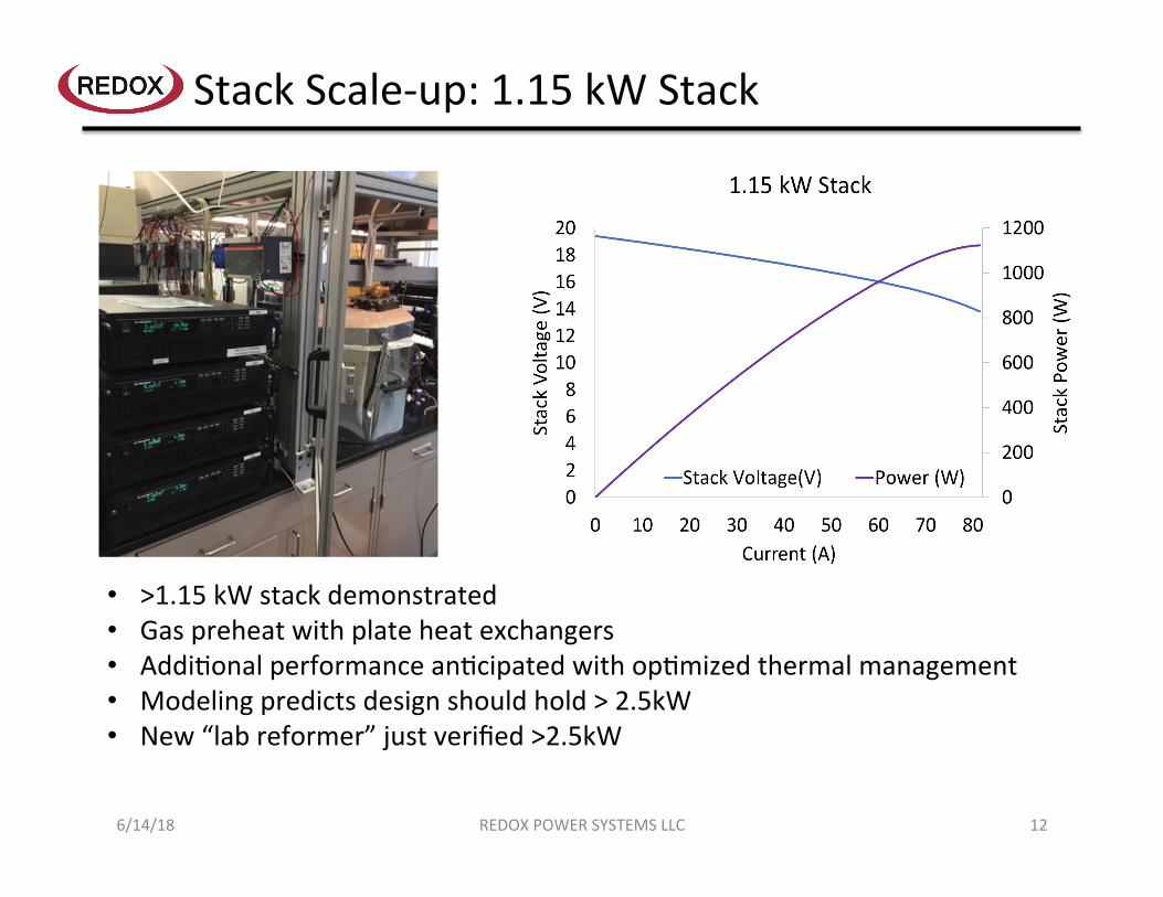
StackScale-up:1.15kWStack
REDOXPOWERSYSTEMSLLC
• >1.15kWstackdemonstrated• Gaspreheatwithplateheatexchangers• AddiXonalperformanceanXcipatedwithopXmizedthermalmanagement• Modelingpredictsdesignshouldhold>2.5kW• New“labreformer”justverified>2.5kW
126/14/18

DataAnalysis:ThermalManagement
REDOXPOWERSYSTEMSLLC
• MulX-physicsmodeling– Modelvalidatedusingcalculated
celltemperaturesfromexperimentallymeasuredvalues
– Modelthenusedtoprobewaystoimprovethermalmanagement
• Temperaturegradientacrosseachcellwithin1.15kWstack– Largestgradientsneargas
manifold– Majorityofthecellshave
gradientof~25°Cto30°C
136/14/18

Redox’sNaturalGasTestFacility(NGTF)
REDOXPOWERSYSTEMSLLC
• DedicatedsiteforconXnuousNGuse,nogasbo^lesrequired– Desulfurizedandrawfeeds
available• Presentlycanaccommodate
2.5kWstacksineachof2teststaXons– Testbenchisdesignedforrobust
operaXonoverlongperiodsofXme
• SeveralNGReformingsystemsavailable,upto9kWstackfeed
• Secondtestbenchhousesanislandedsystemprototype:onlyfacilityXe-inisNG
2.5kWStackTestKilns
StackTestHood BOP/SystemHood
Lab-Controlled
FuelReformer(s)
146/14/18

Lab-ControlledPipelineNGSteamReformer
H2 CH4 CO CO2 H2O
Feed to Reformer 0% 100% 0% 0% 5.6:1 S:C
Feed to Stack (GC Measurement) 67.5% 10.1% 8.8% 13.2% Bal.
Thermodynamic Equilibrium Values
78.1% 0.1% 7.8% 13.7% Bal.
REDOXPOWERSYSTEMSLLC
Reformer
Meteredsteam
Desulfurized,pipelinenaturalgas
FeedtoStack
FeedtoReformer
Stacktestkiln
Reformercapacitygoodfor>2.5kWstack
ShakeDownTest#1(650°C)
ShakeDownTest#2(600°C)
156/14/18

REDOXPOWERSYSTEMSLLC
Red-OxRobustSOFCStacksforAffordable,ReliableDistributedGeneraOonPowerSystems
(DE-FE0027897)
166/14/18

Red-OxStabilityNeededinSOFCs
JournalofPowerSources195(2010)5452–5467
Red-oxcyclescanbeexpectedduringlong-termfuelcelloperaXon• InterrupXonsinfuelsupply• TransientSOFCoperaXon(e.g.,shutdown)
Ni-cermetanodespronetomechanicalfailureduringredoxcycling
~69vol%expansionofNiàNiO
SoluXon:AllceramicanodeàsmallΔoxygen=smalldimensionalchange(0.4vol%)
Line
ar
Expansion[%
]
650oC
0.4vol%
NocracksaZer9redoxcycles!
REDOXPOWERSYSTEMSLLC 176/14/18

All-CeramicAnodeSOFCPerformance
• HighpowerdensiXes• ~0.75W/cm2@550°C• ~0.3W/cm2@450°C
• AcceptableelectronicconducXvity
Buboncelldata AnodeelectricalconducVvity
REDOXPOWERSYSTEMSLLC 186/14/18
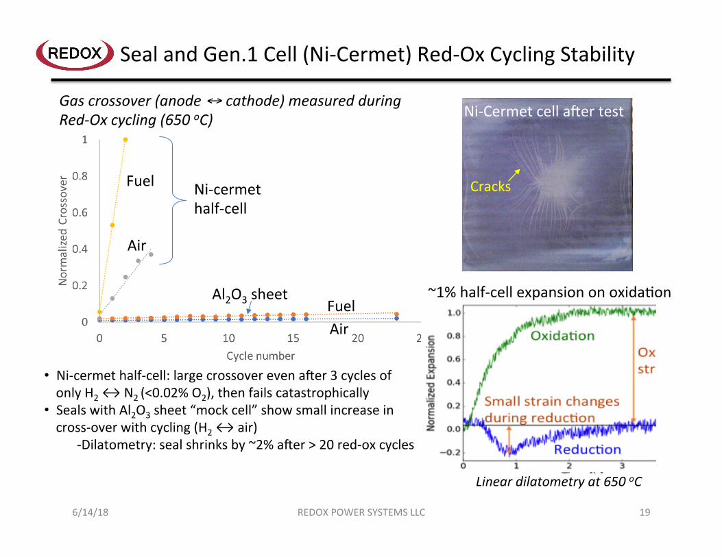
SealandGen.1Cell(Ni-Cermet)Red-OxCyclingStability
Ni-Cermetcelladertest
Cracks
Gascrossover(anode↔cathode)measuredduringRed-Oxcycling(650oC)
Fuel
Air
FuelAir
Ni-cermethalf-cell
Al2O3sheet
• Ni-cermethalf-cell:largecrossoverevenader3cyclesofonlyH2↔N2(<0.02%O2),thenfailscatastrophically
• SealswithAl2O3sheet“mockcell”showsmallincreaseincross-overwithcycling(H2↔air)
-Dilatometry:sealshrinksby~2%ader>20red-oxcycles
~1%half-cellexpansiononoxidaXon
Lineardilatometryat650oC
REDOXPOWERSYSTEMSLLC 196/14/18

SOFCTesXngCapabiliXes
BiologicBCS-815
• 8-channel• 15A/channel• PotenXostat• Impedanceanalyzer• àMini-cellshortstack
and5x5stacktesXng
REDOXPOWERSYSTEMSLLC 206/14/18

ScalingforAll-CeramicAnodeManufacturing
• ProducXon-scaletapecasXngandlaminatemanufacturewithproducXonpartners
• ProducXon-scalecellfiringwithproducXonpartners• MulXplecommercial-scalecastsofall-ceramicanodeproducXontape
• Successfullyfabricatedandfired>3010cmby10cmlaminates
• ProducXoncastalternaXveelectrolyteandanodefuncXonallayerstailoredforall-ceramicanodecells
• FutureworkinvolvesintroducingmodifiedanodestructureinproducXonrunsandconXnuedcasXngforlarge-scalestackneeds
REDOXPOWERSYSTEMSLLC 216/14/18

FlatAll-CeramicAnodeCells
CellProfile
10cmx10cmAll-CeramicAnodeCell
• Achievedveryflatall-ceramicanodecellsfabricatedatR&D,and“producVon”scale
• Demonstratedfiringinlarge“producVon”kilns
REDOXPOWERSYSTEMSLLC 22
CellProfileOnly0.039μmvariaXon(max–min)
Profileslice
6/14/18

3-cell5cmx5cmAll-CeramicAnodeStack
600°C
• FirststackdemonstraVonofR&D-scalefabricatedcells• LowASR~0.19Ω-cm2at600°C
REDOXPOWERSYSTEMSLLC 236/14/18

3-cell10cmx10cmAll-CeramicAnodeStack
600°C
1ststackdemonstraVonof“producVon”castandlaminatedGen-3cells
REDOXPOWERSYSTEMSLLC 246/14/18

10-cell10cmx10cmAll-CeramicAnodeStack
<1Win2017 154Win2018
600°C154W
“ProducXon”materials
REDOXPOWERSYSTEMSLLC 256/14/18
*Note:CellperformancenotfullyopXmized.AddiXonalpoweroutofsamesizestackbyendofproject.
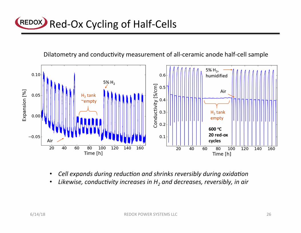
Red-OxCyclingofHalf-Cells
• CellexpandsduringreducVonandshrinksreversiblyduringoxidaVon• Likewise,conducVvityincreasesinH2anddecreases,reversibly,inair
DilatometryandconducXvitymeasurementofall-ceramicanodehalf-cellsample
REDOXPOWERSYSTEMSLLC 266/14/18
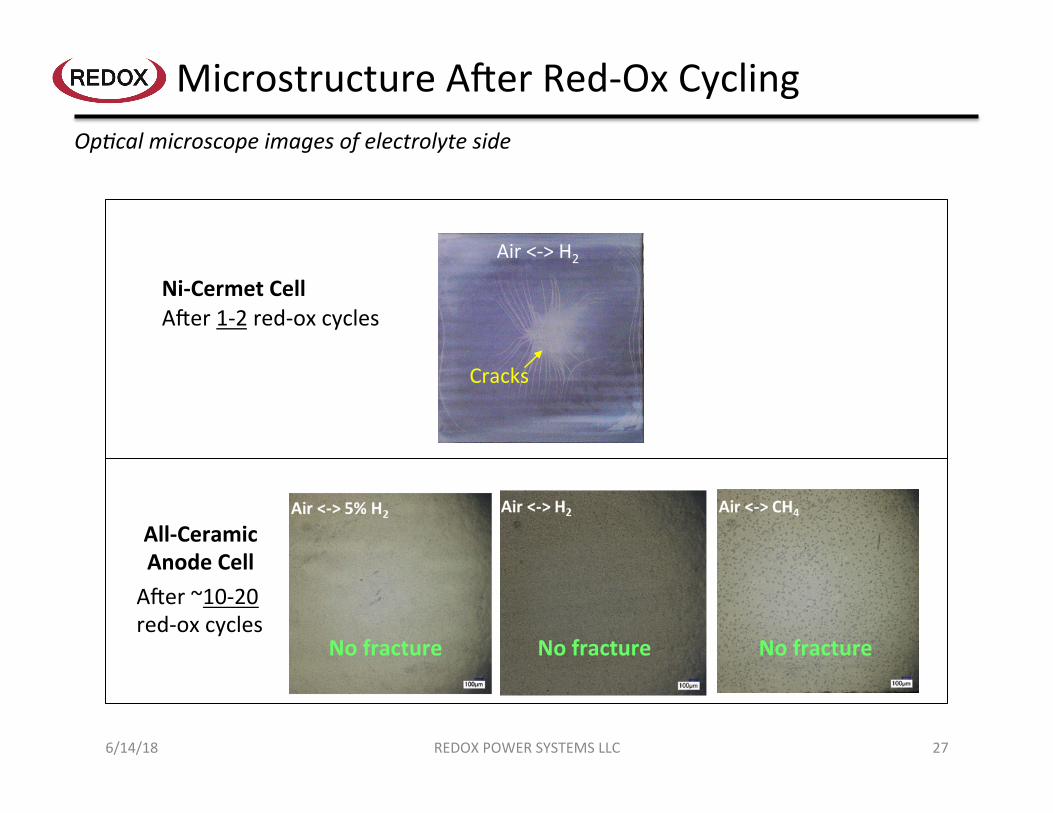
MicrostructureAderRed-OxCyclingOpVcalmicroscopeimagesofelectrolyteside
REDOXPOWERSYSTEMSLLC 27
Nofracture Nofracture Nofracture
Air<->H2
Cracks
Ni-CermetCell
All-CeramicAnodeCell
Ader1-2red-oxcycles
Ader~10-20red-oxcycles
6/14/18

Red-OxCycling5x5SOFCs
• 3red-oxcycleswithminimalASRandOCVdegradaXon
• Furthercyclingàincreaseingascross-overindicaXngcellfracture
• FutureworkincludesconXnuedanodestructuremodificaXon
Improvementstoanodestructureof5x5cellsenablesimprovedred-oxcycling@600°C
Stablegasx-over
StablevoltageH2onanode
N2*on
anode
*N2has~0.1%O2impurity
Red-oxcycles
~StableASRonfirst3red-oxcycles
REDOXPOWERSYSTEMSLLC 286/14/18
H 2OatC
atho
de(a.u.)

AcceleratedTesXng:CathodeDegradaXon
GEN1mini-cellsagedexsituat650°CinairforindicatedVme,thentested
1,000h300h20h
LowfrequencyZ(ohmic+polarizaXon)
HighfrequencyZ(ohmic)
• IncreasedexsituagingresultsinlessIniValohmicburn-in(<60h)àohmicburn-intakesplaceduringexsituaging,likelycathode/contactrelated
• Similarly,polarizaVonburn-inannealedintoexsituagedsamples• Long-termincreaseintotalZexpectedinSOFCtestappearstobe“added”to1,000hexsitu
annealedsample
“Burn-in”
REDOXPOWERSYSTEMSLLC 296/14/18

AcceleratedTesXng:StorageCondiXons
EffectofRHonLifeat250C 100%IncreaseinResistance
1500%IncreaseinResistance
%RH LifeinHours(95%Reliability)
LifeinHours(95%Reliability)
40 229178 5.71*1010 60 170 57584 80 4 53 95 0.7 2
ModeloflifeunXlfailure
Datapoints
FailuredistribuXon
• DevicelifeVmedependssignificantlyonfailurethresholdcriteria
• LifeVmeisdramaVcallyshorteratveryhighhumidity(≥60%)at25oC
• FutureworkincludesaddiVonalRH-Tstudiestorefinemodelforall-ceramicanodeandcathodematerials
REDOXPOWERSYSTEMSLLC 306/14/18
Measurementofall-ceramicanodetestspecimen.SimilarbehaviorfoundonLSCFandLSC.
$0
$50
$100
$150
$200
$250
$300
$350
0 5,000 10,000 15,000 20,000 25,000 30,000 35,000 40,000 45,000
CumulativeDiscountedCost($)
Time(hours)
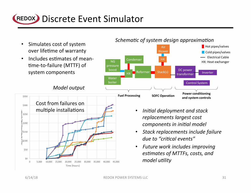
DiscreteEventSimulator
NGpressureboost Reformer
Waterboiler
Stack(s)
Condenser
AirBlower
HX
HXDCpowertransformer Inverter
Hotpipes/valves
Coldpipes/valvesElectricalCable
HX:Heatexchanger
FuelProcessing SOFCOperation Powerconditioningandsystemcontrols
ControlSystem
• SimulatescostofsystemoverlifeXmeofwarranty
• IncludesesXmatesofmean-Xme-to-failure(MTTF)ofsystemcomponents
SchemaVcofsystemdesignapproximaVon
Modeloutput
• IniValdeploymentandstackreplacementslargestcostcomponentsininiValmodel
• Stackreplacementsincludefailuredueto“criVcalevents”
• FutureworkincludesimprovingesVmatesofMTTFs,costs,andmodeluVlity
CostfromfailuresonmulXpleinstallaXons
REDOXPOWERSYSTEMSLLC 316/14/18

NaturalGasPipelineFailures
Pipelinemodel FailurefrequencypredicXon
• IncludesesVmatesfromliteratureonfailurefrequencyofdifferentpipesizes1–mostfailuresoriginatefrom“dig-ins”
• NaturalgaspipelinesesVmatedtonotfailfor>20years
1JHouseEnvironmental,PipelineRiskAnalysis-MountainHouseSpecificPlanIII,2004.h^p://www.sjgov.org/commdev/cgi-bin/cdyn.exe/handouts-mtnhouse_EIR_Appendix_K_Pipeline_R?grp=handouts-mtnhouse&obj=EIR_Appendix_K_Pipeline_R(accessedOctober16,2017).
REDOXPOWERSYSTEMSLLC 326/14/18
(MonteCarlobasedonpipelinemodel)

ProjectsSummary
DE-FE0026189(NETL-1)• ImprovedstackassemblyandQCprocedures• Stackscale-upforimproveddesign:1.15kWstackdemonstrated• >2.5kWlabreformerverifiedalongwithrestofsetupfortesXng2.5kWstack• CellproducXonrampeduptobeginmovingtoward2.5kWstack
DE-FE0027897(NETL-2)• Improvedflatnessoffiredall-ceramicanodehalf-cells• Scaledupall-ceramicanodeproducXonwithtapecasts,laminaXon,andfiring• Successfullytested10-cell10x10all-ceramicanodestack• Manufacturingcostanddiscreteeventsimulatormodelsinworkablestate,
refiningwithimprovedparameters
REDOXPOWERSYSTEMSLLC 336/14/18

Acknowledgments
REDOXPOWERSYSTEMSLLC 34
• NETLProjectManager• SethLawson
• UniversityofMaryland• CALCE(accelerated/lifecycletestplans/economicmodeling)• EnergyResearchCenter(fundamentalR&D)
6/14/18


