
FIXED AND MOVABLE LASER SYSTEMS FOR ALIGNMENT AND POSITIONING IN INDUSTRY AND CRAFTS
EN
LASERP O I N T - , C R O S S - A N D L I N E L A S E R C A T A L O G U E

Point, crosshair or linelasers are used to align or to position objects in industry and crafts. They replace rulers, stops, measuring aids or templates. Lasers may show the working points of machines, e.g. the aiming point of drills or needles, or cutting lines of saws. They assist the operator in placing the workpiece at the right position, avoiding crop. Laser lines and spots don‘t move when touched, and you can use both hands for working.
PRECISION WORK AND LESS CROP DUE TO PRECISE ALIGNMENT AND POSITIONING USING LASERS
LAP lasers are robust tools, that simplify and speed up your work.
SIMPLER PROCEDURESSave yourself the cumbersome hand-ling of templates or rulers and the intricate use of measuring aids
FASTER TO THE FINISH LINESwitch on laser. Align workpiece.Work on it. It‘s as simple as that!
PROTECTING SURFACESLasers don‘t leave marks, colour re-sidues or other tracks on sensitive surfaces. They don‘t disperse dirt or humidity.
COST-EFFECTIVELAP lasers will proof themself a profi-table investment soon by saving setup time, working time and material.
Wood
Stone
Plastics
Fabrics
Leather
Composites
Concrete
Paper
Gluelam Trusses
Assembly
Tin
Wind Energy
Textile Industry
Sawmills
Prefabrication
Veneer
Food Industry
Metrology
Metal Construction
Automotive
Masonry
Healthcare
Content Page
Applications 5
Industries 7
Overview 8
LD Laser 11
XtrAlign HD 13
XtrAlign HY 15
XtrAlign FD 17
UD Laser 19
ULTRALINE® 21
SERVOLASER Xpert 23
Brackets 26
Did you know? 28
Laser classes 29
2 3

The field of application for lasers is as manifold as the use of rulers, templates or measuring tools. You have a wide variety of attributes to choose from: point, cross or line; red or green; long or short; fixed or movable laser; fixed focus or focusable; optimised for cameras or for the human eye - LAP offers a wide range of lasers to solve all common tasks. And if you have a special demand, we will find a solution, as we manufacture LAP lasers inhouse, using our own know-how.
THE RIGHT SOLUTION FOR EVERY APPLICATION
ALIGNMENT OF SINGLE OBJECTS
ALIGNMENT OF MULTIPLE OBJECTS
VISUALISATION OF CUTTING LINE
VISUALISATION OF WORKING POINTE
POSITIONING
INSPECTION
MEASUREMENT
4 5

LAP lasers accompany the whole processing in the wood industry. They help aligning the tree trunks at the frame saw and the planks in front of the edger. They show the cutting line of rip saws, sliding table saws, miter saws, band saws and veneer clippers. For more complex tasks and wood processing centers LAP offers the laser projection system WOOD PRO. Contact us for details!
During production of vehicles and accessories you often encounter align-ment tasks, that can easily be taken care of by lasers. You may position seats, align displays, place parts, adjust headlights or check assembly. You need to place parts with organic shape? Ask for our laser projection sys-tems. Where point, cross or line lasers are not sufficient, laser projectors will visualize any outline generated from CAD data on 3D surfaces.
LAP lasers assist during production and processing of natural stone slabs and objects. Line lasers show the cutting line of bridge saws or crosscut saws to use material with as little crop as possible. For complex cutting and milling at processing centers LAP offers the laser projection system STONE PRO. Please contact us for details!
WOOD INDUSTRY
AUTOMOTIVE INDUSTRY AND SUPPLIERS
STONE MASONRY
LAP lasers can also be used for alignment and positioning in industries and crafts not mentioned here, from the small workshop to the large scale industrial production.
You may use LAP lasers to position textiles at sew-ing machines, to align paper coils, to show cut-outs in prefabs, to mark assembly positions, to project reference lines for cameras and much more.
Your application is not mentioned here?
Contact us, we will certainly have a solution for your task - or we will design it for you!
YOUR INDUSTRY
LAP SERVOLASER are standard equipment in the tire industry. The systems with fixed and movable line lasers have been designed based on requi-rements and requests of tire manufacturers and providers of tire building machines. SERVOLASER display center line and edges of the next layer on tire building machines – symmetrically or asymmetrically, controlled by the machines PLC.
TIRE INDUSTRY
76

LAP LASERSAT A GLANCE
LD L
ase
r
Xtr
Alig
n H
D
Xtr
Alig
n H
Y
Xtr
Alig
n FD
UD
La
ser
ULT
RA
LIN
E®
SER
VO
LASE
R
Xp
ert
Laser
Power supply 5 V12 … 30 V DC 15 … 20 V AC
12 … 30 V DC12 … 30 V DC 15 … 20 V AC
4 … 6 V DC12 … 30 V DC, 15 … 30 V AC or 85 … 264 V AC
24 V DC
Laser power 1 … 30 mW 1 … 30 mW 1 … 40 mW 1 … 30 mW 5 … 30 mW 5 … 30 mW 1 … 40 mW
Line length* 1 … 20 m 1 … 20 m 1 … 30 m 1 … 20 m 3 … 12 m 3 … 12 m 1 … 30 m
Optics**
10°, 20°, 30°, 40°, 80° (standard), manually focusable
10°, 20°, 30°, 40°, 80° (standard), manually focusable
10°, 20°, 30°, 40°, 80° (standard), manually focusable
80° Special optics for low mounting position
Patent optics for low mounting position
red: 90°green: 90°blue: 70°(other on request)
Enclosure rating IP 54 IP 67 IP 67 IP 67 IP 42 IP 54 IP 54
Special features Smallest housing
Stainless steel housing, for roughest industrial environment
Stainless steel housing, for roughest industrial environment
Stainless steel housing, for roughest industrial environment
Uniform distribution of brightness along laser line, smallest housing
Uniform distribution of brightness along laser line, integrated ball head mount
Closed housing, 1 or 2 movable lasers, 1 fixed laser optional
Page 11 13 15 17 19 21 23
*depending on ambient light, mounting position and angle **line length depends on opening angle
8 9

81 mm
ø 19 mm ø 15 mm
B2-LD
B3-LD
B2-LD
-K
LD LASER1 … 30 mW
SMALL AND VERSATILE:
Due to manual focussing from 30 mm to ∞, you may achive an extremely fine laserline at any working distance. This makes the LD laser the right choice for applications with changing working distances and projection positions. Flexi-bility is supported by the small housing, allowing to easily fix the laser on working place machines or rails.
FEATURES:
Manually focusable
Point, Line, Cross
Smallest housing
Reverse polarity protected
Available opening angles line: 10°, 20°, 30°, 40°, 80° (standard)
Available opening angles cross: 38°, 62°(standard)
LAP LD lasers are a perfect match for nearly every gap and like to change their working place
LINE LASERSLaser power
Product Laser class*
Line length*
1 mW LAP 1 LDL 1 up to 1 m
3 mW LAP 3 LDL 1 up to 2 m
5 mW LAP 5 LDL 1 up to 4 m
10 mW LAP 10 LDL 1 up to 6 m
15 mW LAP 15 LDL 2 up to 10 m
30 mW LAP 30 LDL 2M up to 20 m
CROSS LASERSLaser power
Product Laser class*
Line length at 1 m distance
1 mW LAP 1 LDX 1 60 cm/90 cm
3 mW LAP 3 LDX 1 60 cm/90 cm
5 mW LAP 5 LDX 2 60 cm/90 cm
10 mW LAP 10 LDX 2M 60 cm/90 cm
15 mW LAP 15 LDX 2M 60 cm/90 cm
30 mW LAP 30 LDX 2M 60 cm/90 cm
POINT LASERSLaser power
Product Laser class
1 mW LAP 1 LDP 2
3 mW LAP 3 LDP 3R
5 mW LAP 5 LDP 3R
10 mW LAP 10 LDP 3B
15 mW LAP 15 LDP 3B
30 mW LAP 30 LDP 3B
Technical dataLaser type, Wavelength Diode, 635 nm, red
(optional: 670 nm)
Power supply 4 … 6 V DC
Application conditions –10 ... +40 C, 35 … 90 % rel. humidity, non-condensing
Enclosure rating IP 54
Divergence 0,5 mrad
MTTF > 30.000 h at 25°C (635 … 670 nm)
Dimensions Length 81 mm, Ø 19 mm (front) /15 mm (back)
Connector M8, 3-pol.
BRACKETS:
DRAWING (1:1):
POWER SUPPLY:
*Sta
ndar
d op
enin
g an
gle
80°
line
/ 62
° cr
oss,
line
leng
th d
epen
ds o
n am
bien
t lig
ht, m
ount
ing
posit
ion
and
angl
e
CONNECTOR CABLE:
BKK
AN
D
B2-LD
10 11

140 mm
ø 25 mm ø 20 mm
B2-H
D
B3-H
D
B2-F
D
B2-F
D-J
B5-H
D
B2-H
D-K
B5-H
D-F
ROBUST AND FLEXIBLE:
Diode lasers of HD series are designed to withstand the day to day use in harsh industrial environment. The water-proof stainless steel housing protects laser diode, electronic circuitry and precision optics.
The laser diode is galvanically seperated from the power supply, which makes the laser extremely resistant to voltage peaks or current variations. The wide range input capacity enables the HD lasers to be used with all typical low vol-tage power nets.
The optics may be focused without tools. Spot size or line width can be adjusted. The line position doesn‘t change during focusing.
FEATURES:
Manually focusable
Point, Line, Cross
„Heavy Duty“, extremely robust
Protected from voltage variations
Reverse polarity protected
Available opening angles line: 10°, 20°, 30°, 40°, 80° (standard)
Available opening angles cross: 38°, 62°(standard)
LINE LASERSLaser power
Product Laser class*
Line length*
1 mW LAP 1 HDL 1 up to 1 m
3 mW LAP 3 HDL 1 up to 2 m
5 mW LAP 5 HDL 1 up to 4 m
10 mW LAP 10 HDL 2 up to 6 m
15 mW LAP 15 HDL 2 up to 10 m
30 mW LAP 30 HDL 2M up to 20 m
CROSS LASERSLaser power
Product Laser class*
Line length at 1 m distance
1 mW LAP 1 HDX 1 60 cm/90 cm
3 mW LAP 3 HDX 1 60 cm/90 cm
5 mW LAP 5 HDX 2 60 cm/90 cm
10 mW LAP 10 HDX 2M 60 cm/90 cm
15 mW LAP 15 HDX 2M 60 cm/90 cm
30 mW LAP 30 HDX 2M 60 cm/90 cm
POINT LASERSLaser power
Product Laser class
1 mW LAP 1 HDP 2
3 mW LAP 3 HDP 3R
5 mW LAP 5 HDP 3R
10 mW LAP 10 HDP 3B
15 mW LAP 15 HDP 3B
30 mW LAP 30 HDP 3B
Technical dataLaser type, Wavelength Diode, 635 nm, red
Power supply 12 ... 30 V DC, 15 ... 20 V AC
Application conditions –10 ... +40 C, 35 ... 90 % rel. humidity, non-condensing
Enclosure rating IP 67
Divergence 0,5 mrad
MTTF > 30.000 h at 25°C (635 … 670 nm)
Dimensions Length 140 mm, Ø 25 mm (front) /20 mm (back)
Connector M12, 4-pol.
LAP XtrAlign HD lasers don‘t resent being treated harshly or being pelted with any kind of chips.
DRAWING (1:1):
BRACKETS:
POWER SUPPLY:
*Sta
ndar
d op
enin
g an
gle
80°
line
/ 62
° cr
oss,
line
leng
th d
epen
ds o
n am
bien
t lig
ht, m
ount
ing
posit
ion
and
angl
e
CONNECTOR:
BKK
AN
D
B2-H
D
trAlign HD1 … 30 mW
12 13

140 mm
ø 25 mm ø 20 mm
B2-H
D
B3-H
D
B2-F
D
B2-F
D-J
B5-H
D
B2-H
D-K
B5-H
D-F
GREEN, BRIGHT, ROBUST:
Lasers of HY series with green laser beam are used, when visibility of red lasers is no longer sufficient. This may occur on adverse surfaces (e.g. red or black, wet stone) or bright ambient illumination (sunlight). Green light has a visibility about five times higher compared to red light, because human eyes have their maximum sensitivity in this wavelength area.
The robust housing made of stainless steel protects laser, electronic circuitry and precision optics. Thanks to a compact design and reduced weight the laser can be used just about anywhere.
FEATURES:
Improved longevity due to diode laser source
Manually focusable
Optimal visibility of green beam
„Heavy Duty“, extremly robust
Available opening angles line: 10°, 20°, 30°, 40°, 80° (standard)
Available opening angles cross: 38°, 62°(standard)
LINE LASERSLaser power
Product Laser class*
Line length*
1 mW LAP 1 HYL 1 up to 1 m
3 mW LAP 3 HYL 1 up to 2 m
5 mW LAP 5 HYL 1 up to 4 m
10 mW LAP 10 HYL 2 up to 6 m
15 mW** LAP 15 HYL 2 up to 10 m
30 mW** LAP 30 HYL 2M up to 20 m
40 mW** LAP 40 HYL 3R up to 30 m
CROSS LASERSLaser power
Product Laser class*
Line length at 1 m distance
1 mW LAP 1 HYX 1 60 cm/90 cm
3 mW LAP 3 HYX 1 60 cm/90 cm
5 mW LAP 5 HYX 2 60 cm/90 cm
10 mW LAP 10 HYX 2 60 cm/90 cm
15 mW** LAP 15 HYX 2 60 cm/90 cm
30 mW** LAP 30 HYX 2M 60 cm/90 cm
40 mW** LAP 40 HYX 2M 60 cm/90 cm
POINT LASERSLaser power
Product Laser class
1 mW LAP 1 HYP 2
3 mW LAP 3 HYP 3R
5 mW LAP 5 HYP 3R
10 mW LAP 10 HYP 3B
15 mW** LAP 15 HYP 3B
30 mW** LAP 30 HYP 3B
40 mW** LAP 40 HYP 3B
Technical dataLaser type, Wavelength Diode, 520 nm, green
Power supply 12 ... 30 V DC
Application conditions –10 ... +40 C, 35 ... 90 % rel. humidity, non-condensing
Enclosure rating IP 67
Divergence 0,5 mrad
MTTF > 30.000 h at 25°C
Dimensions Length 140 mm, Ø 25 mm (front) /20 mm (back)
Connector M12, 4-pol.
Get the green light for your production.
DRAWING (1:1):
BRACKETS:
POWER SUPPLY:
*S
tand
ard
open
ing
angl
e 80
° lin
e /
62°
cros
s, lin
e le
ngth
dep
ends
on
ambi
ent l
ight
, mou
ntin
g po
sitio
n an
d an
gle
**LA
P br
acke
t or h
eatsi
nk re
quire
d
CONNECTOR: HEATSINK:
BKK
AN
D
B2-H
D
Cooling Element optional
trAlign HY1 … 40 mW
14 15

B2-H
D
B3-H
D
B2-F
D
B2-F
D-J
131 mm
ø 25 mm ø 20 mm
B2-H
D-K
SAFE AND WATERPROOF:
FD diode lasers are designed for use in rough industrial envi-ronment. A waterproof housing protects laser diode, electronic circuitry and precision optics.
FEATURES:
Fixed focus
Small, robust stainless steel housing
IP 67LINE LASERSLaser power
Product Laser class*
Line length*
1 mW LAP 1 FDL 1 up to 1 m
3 mW LAP 3 FDL 1 up to 2 m
5 mW LAP 5 FDL 1 up to 4 m
10 mW LAP 10 FDL 2 up to 6 m
15 mW LAP 15 FDL 2 up to 10 m
30 mW LAP 30 FDL 2 up to 20 m
Technical dataLaser type, Wavelength Diode, 635 nm, red
Power supply 12 ... 30 V DC, 15 ... 20 V AC
Application conditions –10 ... +40 C, 35 ... 90 % rel. humidity, non-condensing
Enclosure rating IP 67
Divergence 0,5 mrad
MTTF > 30.000 h at 25°C
Dimensions Length 131 mm, Ø 25 mm (front) /20 mm (back)
Connector M12, 4-pol.
LAP XtrAlign FD lasers can‘t be harmed easily. Waterproof and peak protected they are always in line with their tasks.
DRAWING (1:1):
BRACKETS:
POWER SUPPLY:
*Sta
ndar
d op
enin
g an
gle
80°,
line
leng
th d
epen
ds o
n am
bien
t lig
ht, m
ount
ing
posit
ion
and
angl
e
CONNECTOR:
BKK
AN
D
B2-H
D
trAlign FD1 … 30 mW
16 17

70 mm
ø 23 mm ø 15 mm
B2-LD
B3-LD
B2-LD
-K
The LAP UD Laser best performs near your workpiece.
UD LASER5 … 30 mW
LOW MOUNTING SPECIALIST:
Diode lasers of LAP UD Series are designed for installation low above the working surface.
The UD series was the answer on customers requests for a laser with small housing like LD series, line length and quality of ULTRALINE to be built in low above working level. The main target for UD lasers are veneer- or sheet metal shears, as well as any place where you have little headroom but you need a long line, starting directly below the laser.
You need a 4 m line, you only have 50 cm of height and the laser must be installed on one side of the opening?
Then you need a UD laser!
FEATURES:
Small housing
Extremely low mounting position
Special optics for laser line with homogeneous brightness distribution
LINE LASERSLaser power
Product Laser class
Line length*
5 mW LAP UD-PL 1 up to 3 m
10 mW LAP UD-XL 2 up to 6 m
15 mW LAP UD-XXL 2 up to 9 m
30 mW LAP UD-XXXL 2M up to 12 m
Technical dataLaser type, Wavelength Diode, 635 nm, red
Power supply 4 … 6 V DC
Application conditions –10 ... +40°C, 35 … 90 % rel. humidity, non-condensing
Enclosure rating IP 42
Divergence 0,5 mrad
MTTF > 30.000 h at 25°C
Dimensions Length 70 mm, Ø 23 mm (front) /15 mm (back)
Connector M8, 3-pol.
DRAWING (1:1):
*Lin
e le
ngth
dep
ends
on
ambi
ent l
ight
, mou
ntin
g po
sitio
n an
d an
gle
Brightness distribution standard optics
Brightness distribution UD special optics
POWER SUPPLY:
BRACKETS:
CONNECTOR CABLE:
BKK
AN
D
B2-LD
18 19

BHW
Z
123 mm
81 mm
BRIGHT AND VERSATILE:
Diode lasers of LAP ULTRALINE® series are designed for instal-lation low above the working surface. With innovative design of patented optics ULTRALINE® laser solve two problems:
First, you get a higher and more constant brightness of the laser line. The line starts directly below the housing and remains cons-tant in brightness over nearly the whole line length. The lumino-sity at the end of the line is twice as high compared to a laser of same power with normal optics !
Second, the shape and size of the housing enable low mounting at the side with the line starting directly below the laser.
FEATURES:
Low mounting position
Integrated ball head mount
Patented optics for homogeneous brightness along the line
Technical dataLaser type, Wavelength Diode, 635 nm, red
Power supply 12 … 30 V DC, 15 … 30 V AC or 85 … 264 V AC
Application conditions –10 ... +40°C, 35 ... 90 % rel. humidity, non-condensing
Enclosure rating IP 54
Divergence 0,5 mrad
MTTF > 30.000 h at 25°C
Dimensions (230 V) 186 mm × 35 mm × 81 mm
Dimensions (24 V) 123 mm × 30 mm × 81 mm
Connector (24 V) M12, 4-pol.
LINE LASERSLaser power
Product Laser class
Line length*
5 mW LAP UL-PL 2 up to 3 m
10 mW LAP UL-XL 2 up to 6 m
15 mW LAP UL-XXL 2M up to 9 m
30 mW LAP UL-XXXL 2M up to 12 m
Der LAP ULTRALINE®–ball head and brains with patented optics
DRAWING (1:1):
POWER SUPPLY:
BRACKETS:
Brightness distribution standard optics
Brightness distribution ULTRALINE® special optics
*Lin
e le
ngth
dep
ends
on
ambi
ent l
ight
, mou
ntin
g po
sitio
n an
d an
gle
CONNECTOR:
ULTRALINE®
5 … 30 mW
20 21

CONTROLLED MOVEMENT:
The LAP SERVOLASER Xpert is a flexible laser positioning system with fixed and movable line laser modules.
In most applications, SERVOLASER Xpert project two parallel lines in varying positions, controlled by product specifications.
Depending on configuration you get different moving ranges:
■ Full range (F): one laser module moves the whole range
■ Max range (M): two laser modules move the whole range independently. At both ends, the range of the second module is reduced by the width of the first module.
■ Symmetrical (S): two laser modules move synchronously in relation to the middle of the range
Technical DataNumber of modules 1 or 2 movable lasers in one housing. 2, 3 or
4 movable lasers in one system. Fixed center laser optional.
Wavelengths* 635 nm (red), 520 nm (green), 450 nm (blue)
Laser power 1 ... 40 mW (dimmable)
Laser classes 1, 2, 2M, 3R depending on laser power and opening angle
Standard-opening angle of laser modules
red, green: 90°; blue: 70°; other opening angles on request
Moving range up to 2600 mm
Positioning speed up to 1000 mm/s
Projection accuracy from ± 0.2 mm **
Line width from 0.5 mm (FWHM)
Protection class IP 54
Operating temperature 0 ... 40°C
Power supply 24 V ± 20 %Interface EtherNet/IP™ (further interfaces on request)
Model Range of Move-ment [mm]
Dimensions L × W × H [mm]
XS 600 1004 x 177 x 192
S 1000 1424 × 177 × 192
M 1200 1604 × 177 × 192
L 1600 2024 × 177 × 192
XL 1900 2324 × 177 × 192
XXL 2100 2504 × 177 × 192
XXXL 2600 2984 × 177 × 192
*
free
sele
ctio
n an
d co
mbi
natio
n
** d
epen
ding
on
rail
leng
th a
nd p
roje
ctio
n di
stanc
e
FEATURES:
More color
Free combination of red, blue and green modules
More power
Modules with up to 40 mW laser power improve visibility especially on matte or black surfaces
Higher precision
Projection accuracy from ± 0.2 mm
Higher speed
Modules move with up to 1000 mm/s
Better communication
EtherNet/IP™ (further interfaces on request)
More configurations
Moving ranges up to 2600 mm, combination of two rails with up to 4 moving laser modules
SERVOLASER pert 1 … 40 mW
22 23

Moving range [mm] Model Size approx. (L×B×H)
600
1000
1200
1600
1900
2100
2600
DIMENSIONS
CONFIGURATIONS
S 1400 × 180 × 190 mm
XS 1000 × 180 × 190 mm
L 2000 × 180 × 190 mm
XXL 2500 × 180 × 190 mm
M 1600 × 180 × 190 mm
XL 2300 × 180 × 190 mm
XXXL 3000 × 180 × 190 mm
Customized Models
PREFIX
…
XS 0
D4
D5 ICC
IPB
D6 IPN
IM
M L1
F L2
S L2M
L3R
SYMMETRICAL 2M
3R
LASER CLASS
FULL RANGE 2
MAX RANGE
NO LASER
RED LASER
GREEN LASER
BLUE LASER
OPENING ANGLE
INTERFACES
90°/ 70°
60° CC-LINK
PROFIBUS
PROFINET
MODBUS/TCP
IE ETHERNET/IP (STANDARD)
40°
FOCUSING DISTANCE 0.1 … 9.9m IN STEPS OF 0.1m
1
XXXL 3
S 1
M 2
SLX S
FIX LEFT
RIGHT
1 2 2 L1 D4 1.3 IEMODEL
SLX – Model F - 0 - 1 - 0
SLX – Model F - 2 - 1 - 0
SLX – Model S - 0 - 3 - 3
SLX – Model S - 1 - 2 - 2
SLX – Model M - 0 - 1 - 3
SLX – Model M - 1 - 2 - 3
POSITIONING ACCURACY
Most providers of positioning systems define accuracy as „posi-tioning accuracy“, meaning how precise and repeatable the laser module can be moved to a certain position on the linear rail. These values don‘t take into account other errors or toleran-ces besides the movement. If the module has minimal backlash, the projection angle may vary depending on whether a correct position is reached from the left or from the right. In some meters distance, this may cause deviations of some millimeters or even centimeters. Positioning accuracy neither defines angular accu-racy nor parallelity of the displayed laser lines.
PROJECTION ACCURACY
At the end of the day, it is crucial for the user, that the projec-ted laser line is exactly at the required position. So LAP offers a projection accuracy (at a certain distance). This value not only covers the positioning accuracy, but also all other causes for deviations.
To reach maximum precision, LAP puts maximum effort in the whole process: selection and testing of finest components; manual assembly by experienced product specialists; adjust-ment and calibration in own test laboratory on testing equip-ment developed only for this product; 48 hours of test run before delivery; quality management with 100% coverage.
EXEMPLIFICATION: ANGULAR ERROR AROUND xM
Laser source rotated around xM
Laser ModuleMoving Rail
≠90°
Laserline ideallyprojected
Laserline actually projected
xM
EXEMPLIFICATION: ANGULAR ERROR AROUND yM
Laser ModuleMoving Rail
Laserline ideally projected Laserline actually projected
Deviation of laser sourcefrom right angle withinlaser module
≠90°yM
24 25

2
5°
5°
F
F
360°
F4°
5°
B2-LD
B3-LD
B2-LD
-K
B2-H
D
B3-H
D
B2-F
D
B2-F
D-J
BHW
Z
B5-H
D
B5-H
D-F
ULTRALINE®
B2-H
D-K
B3-LD / B3-HD
B2-FD-J BHWZ
B5-HD B2-FD
B2-LD-K / B2-HD-K
BRACKETS
BKK AND B2-LD / BKK AND B2-HD
ADJUSTMENT
VERNIERV
V
V
V
BKK
AN
D
B2-LD
BKK
AN
D
B2-H
D
LD│UD Laser XtrAlign HD│HY│FD
26 27
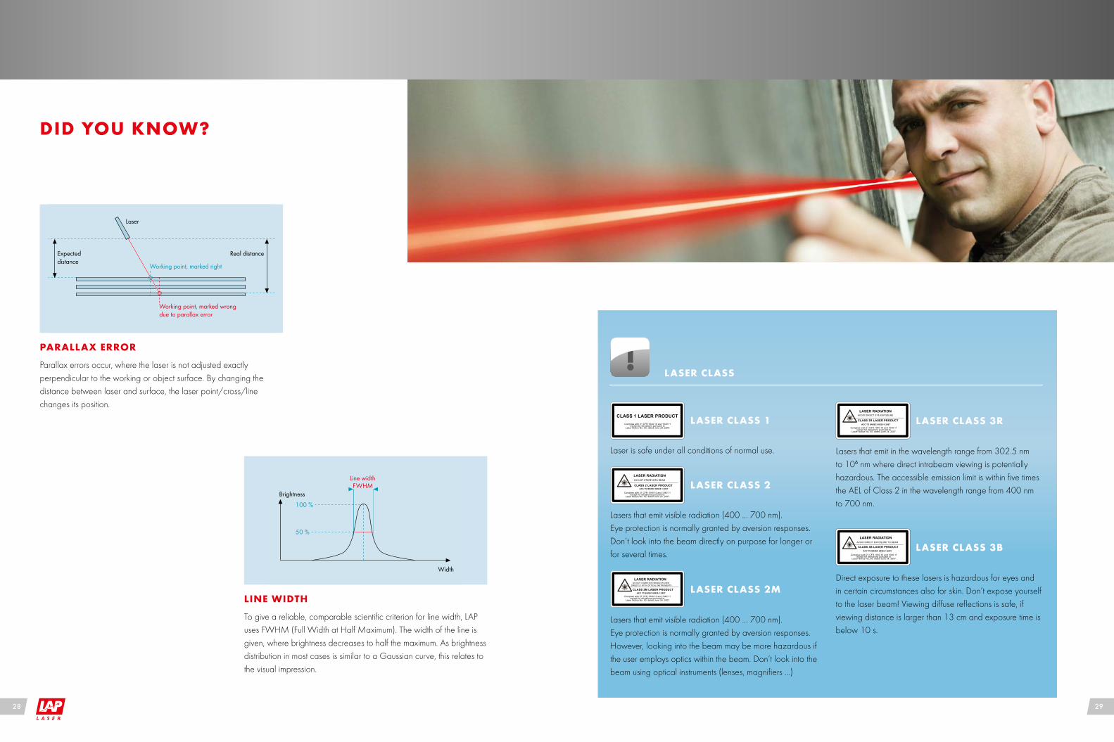
DID YOU KNOW?
Parallax errors occur, where the laser is not adjusted exactly perpendicular to the working or object surface. By changing the distance between laser and surface, the laser point/cross/line changes its position.
PARALLAX ERROR
Laser
Working point, marked wrongdue to parallax error
Working point, marked right
Expected distance
Real distance
To give a reliable, comparable scientific criterion for line width, LAP uses FWHM (Full Width at Half Maximum). The width of the line is given, where brightness decreases to half the maximum. As brightness distribution in most cases is similar to a Gaussian curve, this relates to the visual impression.
LINE WIDTH
50 %
100 %
Brightness
Width
Line widthFWHM
LASER CLASS
Lasers that emit visible radiation (400 ... 700 nm). Eye protection is normally granted by aversion responses. Don‘t look into the beam directly on purpose for longer or for several times.
LASER CLASS 2
Lasers that emit visible radiation (400 ... 700 nm). Eye protection is normally granted by aversion responses. However, looking into the beam may be more hazardous if the user employs optics within the beam. Don‘t look into the beam using optical instruments (lenses, magnifiers ...)
LASER CLASS 2M
Lasers that emit in the wavelength range from 302.5 nm to 106 nm where direct intrabeam viewing is potentially hazardous. The accessible emission limit is within five times the AEL of Class 2 in the wavelength range from 400 nm to 700 nm.
LASER CLASS 3R
Direct exposure to these lasers is hazardous for eyes and in certain circumstances also for skin. Don‘t expose yourself to the laser beam! Viewing diffuse reflections is safe, if viewing distance is larger than 13 cm and exposure time is below 10 s.
LASER CLASS 3B
Laser is safe under all conditions of normal use.
LASER CLASS 1CLASS 1 LASER PRODUCT
LASER RADIATIONDO NOT STARE INTO BEAM
CLASS 2 LASER PRODUCTACC TO EN/IEC 60825-1:2007
Complies with 21 CFR 1040.10 and 1040.11 except for deviations pursuant to
Laser Notice No. 50, dated June 24, 2007.
LASER RADIATIONDO NOT STARE INTO BEAM OR VIEW
DIRECTLY WITH OPTICAL INSTRUMENTS
CLASS 2M LASER PRODUCTACC TO EN/IEC 60825-1:2007
Complies with 21 CFR 1040.10 and 1040.11 except for deviations pursuant to
Laser Notice No. 50, dated June 24, 2007.
LASER RADIATIONAVOID DIRECT EYE EXPOSURE
CLASS 3R LASER PRODUCTACC TO EN/IEC 60825-1:2007
Complies with 21 CFR 1040.10 and 1040.11 except for deviations pursuant to
Laser Notice No. 50, dated June 24, 2007.
LASER RADIATIONAVOID DIRECT EXPOSURE TO BEAM
CLASS 3B LASER PRODUCTACC TO EN/IEC 60825-1:2007
Complies with 21 CFR 1040.10 and 1040.11 except for deviations pursuant to
Laser Notice No. 50, dated June 24, 2007.
28 29

Customizing
Support during site planning
Supply of additional equipment (Mounting accesso-ries, rails, beams …)
Software customizing and add-ons (connection to customer network, barcode handling …)
Installation and commissioning
Training
Maintenance
Substitution units for provisional use during mainte-nance
Exchange of parts subject to regular wear and tear
Cleaning
Adjustment
Updates for software and firmware
Repairs
THE SERVICE
LAP supports you before, during and after the installation of an LAP system. Tens of years of international experience with installation and maintenance of laser systems across virtually all industries make LAP a reliable and competent partner.
Before you decide, we offer intense consulting. We show you the advantages of our technology as well as its limits. We give advice dur-ing site planning and install the system on site. After commissioning, we accompany your first steps until you reach full performance.
Every customer has different requirements concerning maintenance intervals, response time and protection against downtime. Conse-quently, LAP offers every customer an individually tailored package, which may exceed normal performance by far.
You need on-site replacement? 24/7 emergency service? 24h-hotline? Or is replacement within 24 hours, working day service and periodical training of your employees enough? Tell us your wishes – we will find a solution that is sufficient for your needs.
www.LAP-LASER.com
THERE’S EVEN MORE. LAP ENABLES YOU TO MEASURE GEOMETRICAL FEATURES WITHOUT CONTACT
www.LAP-LASER.com
BRING COLOUR TO YOUR LIFE. LAP ALSO PROJECTS OUTLINES AND TEMPLATES. MULTICOLOURED.
LAP DropLine lasers start the laser line directly below the horizontally mounted housing. The line brightness remains virtually constant to the far end.
LAP UltraLine® is the result of the advanced mechanical systems and the unique optoelectronics used to generate and align laser lines for medical and industrial applications.
30 31

ISO 9001ISO 13485
HIGH-TECH QUALITY LASERS BY LAP
LAP GmbH Laser ApplikationenZeppelinstrasse 2321337 LueneburgGermanyPhone +49 4131 9511-95Fax +49 4131 9511-96Email [email protected]
LAP Laser, LLC1830 Airport Exchange Blvd.Suite 110Erlanger, KY 41018USAPhone +1 859 283-5222Fax +1 859 283-5223Email [email protected]
LAP GmbH Laser ApplikationenПредставительство в Москве1, Казачий переулок 7119017 МоскваРоссийская ФедерацияТел. +7 495 7304043Факс +7 495 7304044Email [email protected]
LAP Laser ApplicationsAsia Pacific Pte. Ltd.750A Chai Chee Road#07–07 Viva Business ParkSingapore 469001Phone +65 6536 9990Fax +65 6533 6697Email [email protected]
LAP Laser Applications China Co. Ltd. East Unit , 4F Building # 10 LuJiaZui Software ParkNo. 61 Lane 91 EShan RoadShanghai 200127ChinaPhone +86 21 5047-8881Fax +86 21 5047-8887Email [email protected]
For more than 30 years, LAP has been developing, manufacturing and distributing laser measurement systems, line lasers and laser template projectors for industrial and medical applications. LAP products are high-precision devices Made in Germany.
Using LAP laser systems, our customers improve performance and increase the qual-ity of their products as well as the effective-ness of their processes.
As a result of continuous product innovation, LAP has become a world leader in lasers for projection and measurement. LAP products are setting the standards in a wide range of markets from manufacturing to heavy indus-trial environments and medical applications.
Environmental protection is important to us. We use solar panels, green electricity and roofs planted with grass. Our production is planned by standards of sustainability.
Quality has always been part of our com-mitment. We are content if you are. We know your high demands. To meet your requirements, the quality management of LAP is certified by DIN EN ISO 9001:2008 for industrial products and by DIN EN ISO 13485:2010 for medical engineering products.
www.lap-laser.com/LINELASER
LAP SERVOLASER® and LAP UltraLine® are registered trademarks of LAP GmbH Laser Applikationen. Further designations of products or services may be registered trademarks of LAP GmbH or other organizations; their use by third parties may infringe the rights of the respective owners.
© L
AP
Gm
bH,
MK
T-1
40
01
5 2
.8 e
n, 2
01
8-0
5-2
4

![Ò6 ²79 B2 Eëm ëRÃñqÍ%Ã X íý !å²wc G^els ¯r ü[l] © Ö~ +~Ld ... · Title: Ò6 ²79 B2 Eëm ëRÃñqÍ%Ã X íý !å²wc G^els_ ¯r ü[l] © Ö~ +~Ld: ; +$O iÃS¶ ]Ê](https://cdn.vdocuments.net/doc/165x107/5c89e4ba09d3f26b278b95ec/o6-79-b2-eem-eranqia-x-iy-awc-gels-r-uel-oe-ld-.jpg)


![Classical Section V-belts 5, Y/6 and 8...Typ CONTI-V - Profil A/13 - DIN2215 Ld [mm] Ld [mm] Ld [mm] Ld [mm] Ld [mm] Ld [mm] A 16* 407 437 A 46,5 1180 1210 A 85 2160 2190 A 18* 457](https://cdn.vdocuments.net/doc/165x107/60e95cd6b6215c18f511d258/classical-section-v-belts-5-y6-and-8-typ-conti-v-profil-a13-din2215-ld.jpg)
