
LAT-PR-01967-01 Section 8.2 – Structural Design 1
GLAST LAT Project
CDR/CD3 Review, May 12-16 2003
15 Apr 2003
Martin Nordby [email protected]
With contributions from:With contributions from:
Youssef Ismail John Ku
Mike Foss Rich Bielawski
Michael Lovelette Jim Haughton
Eric Gawehn Larry Wai
Gamma-ray Large Gamma-ray Large Area Space Area Space TelescopeTelescope
LAT Structural SystemsLAT Structural Systems

LAT-PR-01967-01 Section 8.2 – Structural Design 2
GLAST LAT Project
CDR/CD3 Review, May 12-16 2003 AgendaAgenda
• Design Overview
– LAT design
– Design and interface changes since Delta PDR
– CCB actions, trade studies, and open issues
• Peer Review RFA’s and requirements
• Structural analysis model development
• Structural analysis results
– LAT modal analysis
– Distortion analysis
– Interface loads extraction
• Environmental test plans
– Integration and test flow
– Modal survey testing
– Sine vibe and sine burst testing
– Acoustic testing
– Optical and muon surveying
• Summary and conclusions
UPDATE
LAT-PR-01967-01 Section 8.2 – Structural Design 3
GLAST LAT Project
CDR/CD3 Review, May 12-16 2003Mechanical Design OverviewMechanical Design Overview
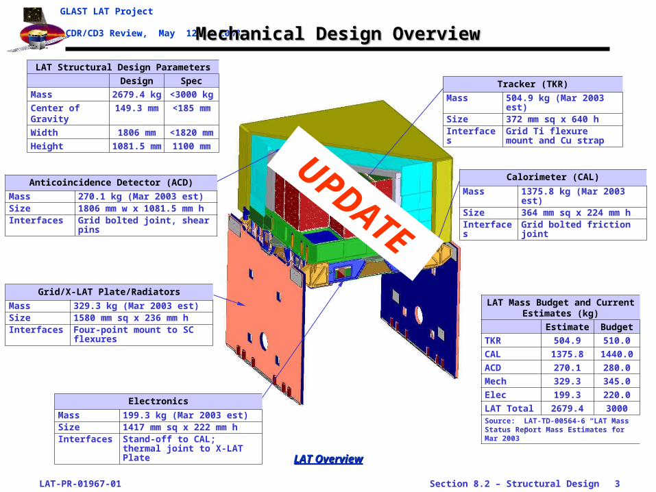
LAT OverviewLAT Overview
Anticoincidence Detector (ACD)
Mass 270.1 kg (Mar 2003 est)Size 1806 mm w x 1081.5 mm hInterfaces Grid bolted joint, shear pins
Electronics
Mass 199.3 kg (Mar 2003 est)Size 1417 mm sq x 222 mm hInterfaces Stand-off to CAL; thermal joint
to X-LAT Plate
Grid/X-LAT Plate/Radiators
Mass 329.3 kg (Mar 2003 est)Size 1580 mm sq x 236 mm hInterfaces Four-point mount to SC
flexures
LAT Structural Design Parameters
Design Spec
Mass 2679.4 kg <3000 kg
Center of Gravity 149.3 mm <185 mm
Width 1806 mm <1820 mm
Height 1081.5 mm 1100 mm
LAT Mass Budget and Current Estimates (kg)
Estimate Budget
TKR 504.9 510.0
CAL 1375.8 1440.0
ACD 270.1 280.0
Mech 329.3 345.0
Elec 199.3 220.0
LAT Total 2679.4 3000Source: LAT-TD-00564-6 “LAT Mass Status Report Mass Estimates for Mar 2003”
Calorimeter (CAL)
Mass 1375.8 kg (Mar 2003 est)Size 364 mm sq x 224 mm hInterfaces Grid bolted friction joint
Tracker (TKR)
Mass 504.9 kg (Mar 2003 est)Size 372 mm sq x 640 hInterfaces Grid Ti flexure mount and
Cu strap
UPDATE

LAT-PR-01967-01 Section 8.2 – Structural Design 4
GLAST LAT Project
CDR/CD3 Review, May 12-16 2003 System Block DiagramSystem Block Diagram
TKR ModuleCFC tray, side walls
Gridmonolithic alum structure
CAL Modulesalum bottom plate
Elec. Boxesalum electronics box
MLI InsulationMLI surrounding underside of LAT
ACDBase Elec Ass’y alum frame
LAT Radiatorson +/- Y sides of LAT Grid
SpacecraftLAT mounting structure
SpacecraftSC bus structure
Solar ArraysS.A. mount
MLISurrounding ACD
LAT Block DiagramLAT Block Diagram
X-LAT Platemonolithic alum structure
Radiator Mnt BktSupport Radiators at corners of Grid
EMI SkirtShields E-Boxes, supports X-LAT Pl
Htr Switch BoxesOperate Radiator heaters
LAT-PR-01967-01 Section 8.2 – Structural Design 5
GLAST LAT Project
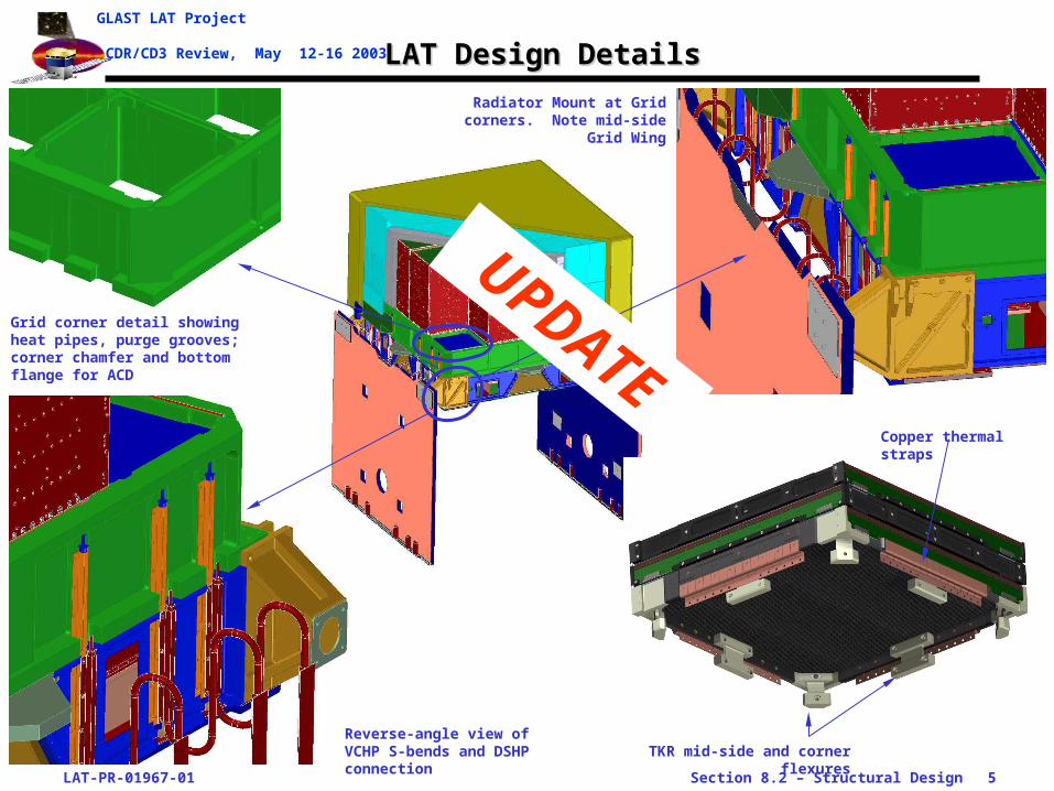
CDR/CD3 Review, May 12-16 2003 LAT Design DetailsLAT Design Details
Grid corner detail showing heat pipes, purge grooves; corner chamfer and bottom flange for ACD
Radiator Mount at Grid corners. Note mid-side Grid Wing
Reverse-angle view of VCHP S-bends and DSHP connection TKR mid-side and corner flexures
Copper thermal straps
UPDATE
LAT-PR-01967-01 Section 8.2 – Structural Design 6
GLAST LAT Project
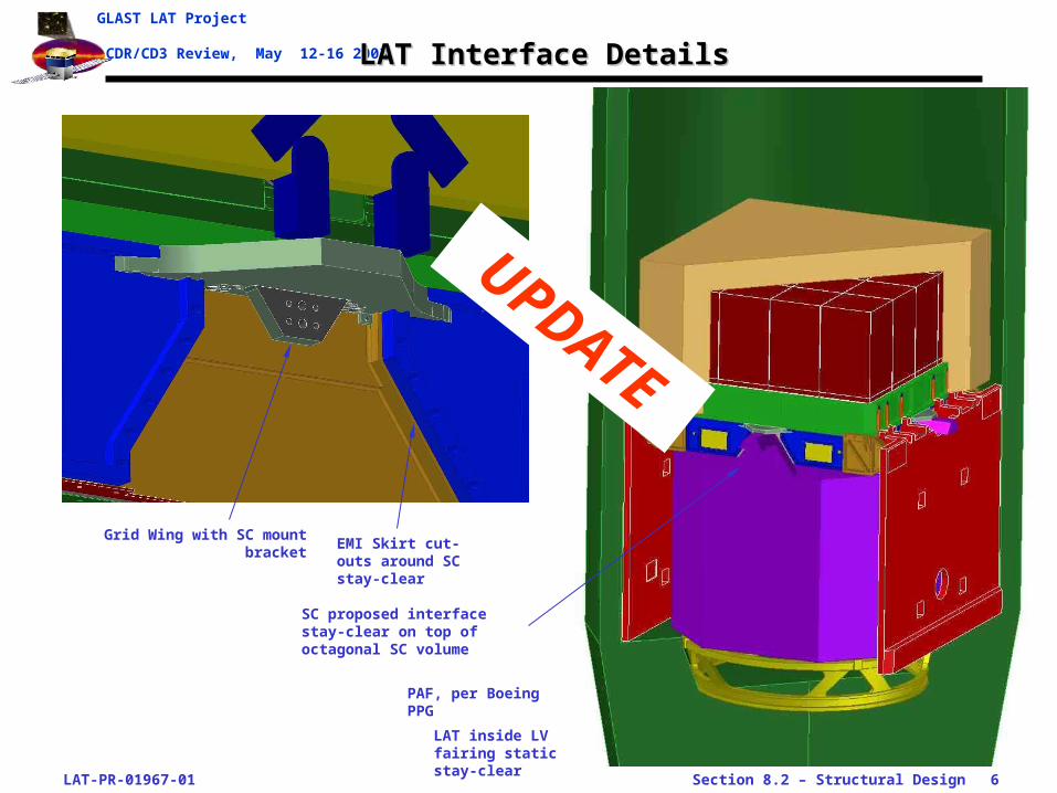
CDR/CD3 Review, May 12-16 2003 LAT Interface DetailsLAT Interface Details
Grid Wing with SC mount bracketEMI Skirt cut-outs around SC stay-clear
LAT inside LV fairing static stay-clear
PAF, per Boeing PPG
SC proposed interface stay-clear on top of octagonal SC volume
UPDATE

LAT-PR-01967-01 Section 8.2 – Structural Design 7
GLAST LAT Project
CDR/CD3 Review, May 12-16 2003LAT Underside Design DetailsLAT Underside Design Details
Upside-down view of a Grid Y mid-side, showing DSHP’s, Grid Wing, and EMI Skirt
Detail of TEM, TPS, and EPU box stack
Empty boxes
EPU boxes
PDU box
GASU box
SIU boxes
TPS (16x)
TEM (16x)
LAT Underside View of LAT Underside View of Electronics BoxesElectronics Boxes
UPDATE

LAT-PR-01967-01 Section 8.2 – Structural Design 8
GLAST LAT Project
CDR/CD3 Review, May 12-16 2003LAT Design Changes Since Delta-PDRLAT Design Changes Since Delta-PDR
• Subsystem changes affecting system performance
– TKR bottom tray re-work: strengthens CC tray in high-stress corner regions
– TKR flexure re-design: accommodates updated bottom tray design and provides for stiffer cantilever mode for TKR
– ACD mass growth: accommodates larger tile overlaps and increase in structural stiffness and strength
• LAT internal interface changes
– Integrated Grid Wing into bottom flange• Incorporated Wing into machined Grid (no longer a bolt-on part)• Tapered wing into a full bottom flange around Grid perimeter to reduce stress concentrations at
SC mount and heat pipe cut-outs
– Changed TKR thermal interface to thermal straps• Copper straps provide compliant joint to Grid
– Stiffened TKR flexure connection to Grid• This was part of TKR bottom tray re-design• Effect was to increase TKR first-mode natural frequency
– Moved Electronics Box structural mount to CAL back plate• Boxes now hard-mounted to CAL plate by way of moment-bearing stand-offs• Cleaner structural design simplifies analysis and test plans for CAL and Electronics groups• Forces on the X-LAT Plate are reduced to just inertial loads of the plate
– X-LAT plate thermal connection changed to V-Therm cloth• Test program underway
– CAL-Grid bolted joint modified to include pins• Development program underway to finalize pinned joint design• Design incorporated into CDR analysis
LAT-PR-01967-01 Section 8.2 – Structural Design 9
GLAST LAT Project
CDR/CD3 Review, May 12-16 2003LAT External Interface Changes Since Delta-PDRLAT External Interface Changes Since Delta-PDR
• Finalized Radiator dimensions and interface
– Modified Radiator aspect ratio at request of Spectrum
– Agreed on final width, based on reduction in spacing between Radiators that was requested by Spectrum
– Agreed on final height, based on final positioning of LAT and PAF stay-clear agreements with Boeing
– Resulting radiator area is 2.78 m2
• Finalized Radiator mount location to SC
– Moved mount location down at request of Spectrum
– This reduced Radiator first-mode natural frequency, but margin to 50 Hz requirements is still large
• Modified LAT-SC mount region
– Finalized bolt pattern and pad size to accommodate Spectrum’s flexure design
– Agreed to final LAT and SC stay-clear geometry around flexure
LAT-PR-01967-01 Section 8.2 – Structural Design 10
GLAST LAT Project
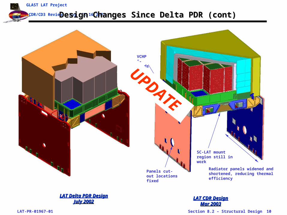
CDR/CD3 Review, May 12-16 2003Design Changes Since Delta PDR (cont)Design Changes Since Delta PDR (cont)
LAT Delta PDR Design LAT Delta PDR Design July 2002July 2002
LAT CDR Design LAT CDR Design Mar 2003Mar 2003
Radiator panels widened and shortened, reducing thermal efficiency
Panels cut-out locations fixed
SC-LAT mount region still in work
VCHP S-bends
UPDATE

LAT-PR-01967-01 Section 8.2 – Structural Design 11
GLAST LAT Project
CDR/CD3 Review, May 12-16 2003Change Control Board Changes Since Delta-PDRChange Control Board Changes Since Delta-PDR
• ACD mass growth
– Added structural mass to increase design margins
– Added mass in scintillating tiles to increase size of tiles and overlap between tiles
• Mechanical Systems mass growth
– Added mass for Grid box additions: Grid Wing, bottom flange, EMI Skirt stiffening, X-LAT thermal straps
– Added mass for slightly increased Radiator area
• Calorimeter mass de-allocation
– Decreased mass allocation to reflect reduction in size of CsI logs
– Log size was reduced to accommodate tolerance stack-up within CFC box structure
• Power allocation update (pending)
– Updated power allocations based on current measured values
– Already using updated allocations in thermal analysis
LAT-PR-01967-01 Section 8.2 – Structural Design 12
GLAST LAT Project
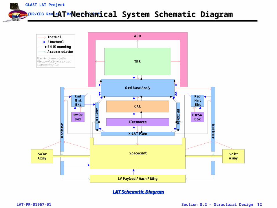
CDR/CD3 Review, May 12-16 2003LAT Mechanical System Schematic DiagramLAT Mechanical System Schematic Diagram
Rad
iato
rRad
iato
r
Grid Base Ass’y
CAL
TKR
ACD
X-LAT Plate
EM
I S
kir
tRadMntBkt
Electronics
Htr SwBox
Spacecraft
LV Payload Attach Fitting
EM
I Skirt
RadMntBkt
Htr SwBox
SolarArray
SolarArray
Thermal
Structural
EMI/Grounding
Accommodation
Direction of arrow signifiesdirection of reliance, structuralsupport or heat flow
LAT Schematic DiagramLAT Schematic Diagram
LAT-PR-01967-01 Section 8.2 – Structural Design 13
GLAST LAT Project
CDR/CD3 Review, May 12-16 2003Trade Studies Since Delta PDRTrade Studies Since Delta PDR
• Moved Electronics Box structural mount to CAL back plate
– Boxes now hard-mounted to CAL plate by way of moment-bearing stand-offs
– Cleaner structural design simplifies analysis and test plans for CAL and Electronics groups
– Forces on X-LAT Plate are reduced to just inertial loads of the plate
• Radiator panel top profile
– Modified panel to a stepped top profile
– Radiator area is maximized, while providing good access volume under the ACD
LAT-PR-01967-01 Section 8.2 – Structural Design 14
GLAST LAT Project
CDR/CD3 Review, May 12-16 2003Structural Interface Open IssuesStructural Interface Open Issues
• CAL-Grid structural joint
– Issue: joint has recently been changed from an all-friction joint to a pinned joint, but analysis and development testing are not yet complete
– Closure plan• Structural analysis underway• Joint testing is underway• Process development work underway
• X-LAT Plate to Electronics box thermal joint
– Issue: thermal strap design was recently abandoned in favor of V-Therm carbon fiber cloth, with much testing yet to be done
– Closure plan• Materials testing• Contamination studies and testing• Thermal properties testing• Joint design and tolerance study
• Radiator-SC strut angle
– Issue: Spectrum proposes to angle the Radiator support struts

LAT-PR-01967-01 Section 8.2 – Structural Design 15
GLAST LAT Project
CDR/CD3 Review, May 12-16 2003Structural RFA’s from Peer ReviewStructural RFA’s from Peer Review
UPDATE
ID # Status RFA Description RFA Response/Closure Plan
LAT-PR-01967-01 Section 8.2 – Structural Design 16
GLAST LAT Project
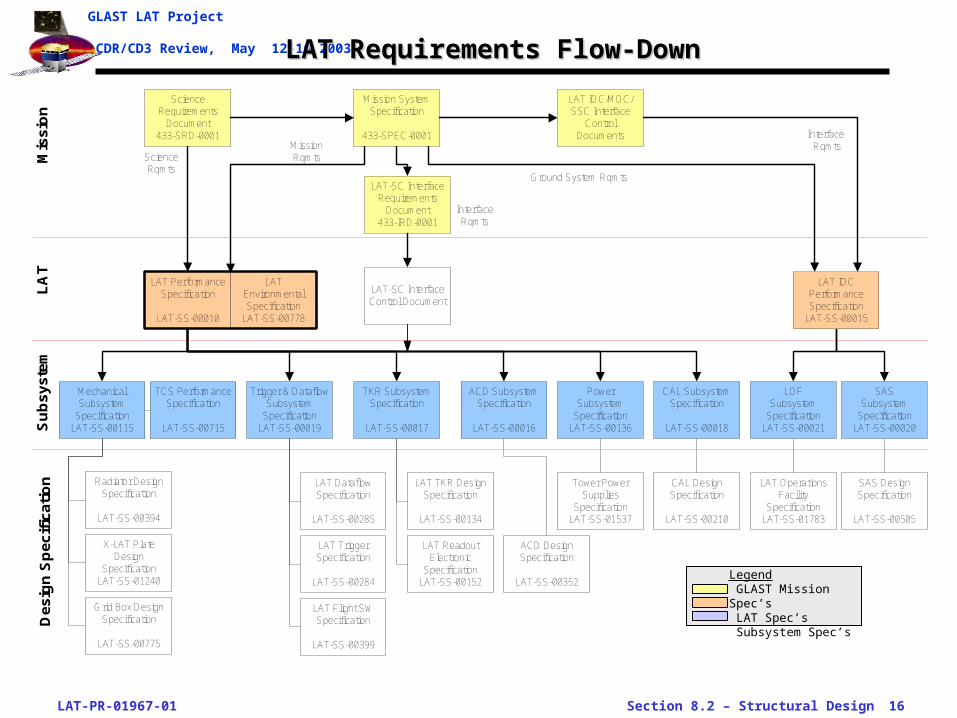
CDR/CD3 Review, May 12-16 2003LAT Requirements Flow-DownLAT Requirements Flow-Down
Mission SystemSpecification
433-SPEC-0001
ScienceRequirements
Document433-SRD-0001
LAT-SC InterfaceRequirements
Document433-IRD-0001
LAT PerformanceSpecification
LAT-SS-00010
ACD SubsystemSpecification
LAT-SS-00016
TKR SubsystemSpecification
LAT-SS-00017
CAL SubsystemSpecification
LAT-SS-00018
Trigger & DataflowSubsystem
SpecificationLAT-SS-00019
SASSubsystem
SpecificationLAT-SS-00020
LOFSubsystem
SpecificationLAT-SS-00021
PowerSubsystem
SpecificationLAT-SS-00136
MechanicalSubsystem
SpecificationLAT-SS-00115
Mis
sio
nL
AT
Su
bs
ys
tem
ScienceRqmts
MissionRqmts
Ground System Rqmts
InterfaceRqmts
Interface Rqmts
TCS PerformanceSpecification
LAT-SS-00715
SAS DesignSpecification
LAT-SS-00505
CAL DesignSpecification
LAT-SS-00210
LAT TriggerSpecification
LAT-SS-00284
LAT TKR DesignSpecification
LAT-SS-00134
LAT OperationsFacility
SpecificationLAT-SS-01783
Tower PowerSupplies
SpecificationLAT-SS-01537
ACD DesignSpecification
LAT-SS-00352
De
sig
n S
pe
cif
ica
tio
n LAT DataflowSpecification
LAT-SS-00285
LAT Flight SWSpecification
LAT-SS-00399
LAT ReadoutElectronic
SpecificationLAT-SS-00152
LAT IOC/MOC/SSC Interface
ControlDocuments
Radiator DesignSpecification
LAT-SS-00394
X-LAT PlateDesign
SpecificationLAT-SS-01240
Grid Box DesignSpecification
LAT-SS-00775
LAT-SC InterfaceControl Document
LATEnvironmentalSpecification
LAT-SS-00778
LAT IOCPerformanceSpecification
LAT-SS-00015
Legend GLAST Mission Spec’s LAT Spec’s Subsystem Spec’s

LAT-PR-01967-01 Section 8.2 – Structural Design 17
GLAST LAT Project
CDR/CD3 Review, May 12-16 2003Key LAT Configuration and Structural RequirementsKey LAT Configuration and Structural Requirements
Parameter Requirement Design Margin ComplyVer.
MethodDriving Req.
LAT ConfigurationLAT mass allocation < 3000 kg 2679.4 kg 320.6 kg Y MLAT vertical center of mass above LIP < 185 mm 149.3 mm 35.7 mm Y MLAT lateral center of mass off Z-axis < 20 mm 1.26 mm 18.74 mm Y MLAT moment of inertia about X-, Y-axes < 1500 kg-m2 1058 kg-m^2 442 kg-m^2 Y ALAT moment of inertia about Z-axis < 2000 kg-m2 1340 kg-m^2 660 kg-m^2 Y AMax Radiator area (#) < 5.88 m^2 5.57 m^2 0.31 m^2 Y IConfigured as 2 separate Radiators OK Y IRadiator max width (#) < 1.903 m 1.896 m 7 mm Y IPositioned according to IRD App. A (#) > 1.84 m sep 1.863 m 22.6 mm Y IMount point for SC support as shown in IRD Appendix A (#)
1.177 m below LIP
OK Y I
Structural, LoadsFixed-base first-mode > 50 Hz 11% Y TTKR alignment during normal LAT operation
< 7arc-sec 1s radial
4.1 arc-sec peak-to-peak
2.9 arc-sec + 5s
Y T, A
Capable of exposure to static-equivalent launch loads
OK Y T, A
Capable of exposure to sinusoidal vibration launch loads
OK Y T
Capable of exposure to acoustic launch loads
OK P T
UPDATE:
Origin of Req
LAT-PR-01967-01 Section 8.2 – Structural Design 18
GLAST LAT Project
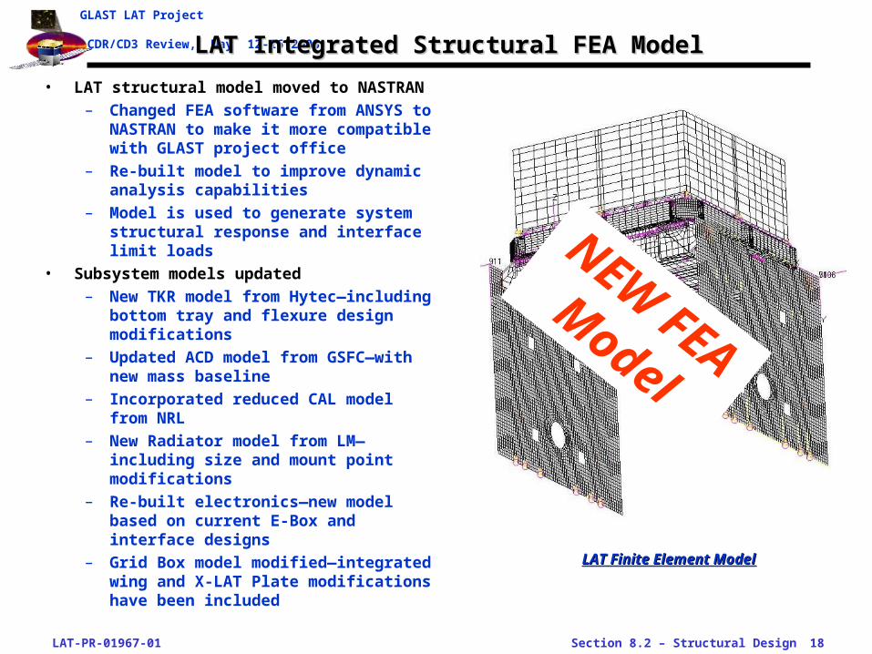
CDR/CD3 Review, May 12-16 2003LAT Integrated Structural FEA ModelLAT Integrated Structural FEA Model
• LAT structural model moved to NASTRAN
– Changed FEA software from ANSYS to NASTRAN to make it more compatible with GLAST project office
– Re-built model to improve dynamic analysis capabilities
– Model is used to generate system structural response and interface limit loads
• Subsystem models updated
– New TKR model from Hytec—including bottom tray and flexure design modifications
– Updated ACD model from GSFC—with new mass baseline
– Incorporated reduced CAL model from NRL
– New Radiator model from LM—including size and mount point modifications
– Re-built electronics—new model based on current E-Box and interface designs
– Grid Box model modified—integrated wing and X-LAT Plate modifications have been included
LAT Finite Element ModelLAT Finite Element Model
NEW FEA
Model
LAT-PR-01967-01 Section 8.2 – Structural Design 19
GLAST LAT Project
CDR/CD3 Review, May 12-16 2003
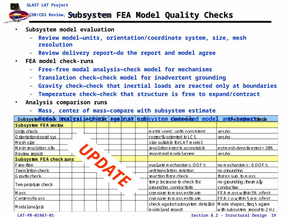
Subsystem Check TKR CAL ACD Elec Rad XLAT Grid Comments Evaluation CriteriaSubsystem FEA reviewUnits check metric used; units consistent yes/noOrientation/coord sys correctly oriented in LCS yes/noMesh size size suitable for LAT modelMesh resolution, qlty resolution error is acceptable est mesh density error < 20%Review report report and model agree yes/noSubsystem FEA check runsFree-free evaluate mechanisms, DOF's no mechanisms; 6 DOF'sTranslation check unit translation, rotation no groundingGravity check reaction force check forces sum to mass
Temperature checktemp increase to check for grounding, conductivity
no grounding; thermally conductive
Mass compare to mass estimate FEA mass within 5% of estCenter of mass compare to mass estimate FEA c.g within 5 mm of est
Modal analysischeck against subsystem detailed model and report
Mode shapes, freq's agree with subsystem report to 2 Hz
Subsystem FEA Model Quality ChecksSubsystem FEA Model Quality Checks
• Subsystem model evaluation
– Review model—units, orientation/coordinate system, size, mesh resolution
– Review delivery report—do the report and model agree
• FEA model check-runs
– Free-free modal analysis—check model for mechanisms
– Translation check—check model for inadvertent grounding
– Gravity check—check that inertial loads are reacted only at boundaries
– Temperature check—check that structure is free to expand/contract
• Analysis comparison runs
– Mass, center of mass—compare with subsystem estimate
– Modal analysis—check against subsystem detailed model and report
UPDATE

LAT-PR-01967-01 Section 8.2 – Structural Design 20
GLAST LAT Project
CDR/CD3 Review, May 12-16 2003LAT FEA Model Boundary ConditionsLAT FEA Model Boundary Conditions
• Accelerations
– Used LAT center-of-mass accelerations from LAT Environmental Spec. for structural load cases
• SC mount boundary condition mimics flexure-type connection
– X-Side SC mount: LAT restrained in the Y- and Z-directions
– Y-Side SC mount: LAT restrained in the X- and Z-directions
• Radiator mounting
– Radiators mounted to Grid through Radiator Mount Bracket beams
– SC boundary condition fixed in Y-direction (out-of-plane) only
LAT F.E.A. Properties and Current LAT EstimatesLAT F.E.A. Properties and Current LAT Estimates
Source: LAT-TD-00564-06 “LAT Mass Status Report, Mass Estimates for Mar 2003,” 7 Mar 2003
LAT Static-Equivalent Design AccelerationsLAT Static-Equivalent Design Accelerations
Source: LAT-SS-00778-01 “LAT Environmental Specification,” March 2003
LAT F.E.A. Model MetricsLAT F.E.A. Model Metrics
LAT F.E.A. Current LAT Est.Subsystem Mass
(kg)Center of
Gravity (m)Mass (kg)
Center of Gravity (m)
TKR 520.1 261.85 505 230.0CAL 1375 -138.55 1376 -148.8ACD 268 348.00 270 318.2Radiators 71.67 -1034.30 77 -1368.6Grid Box 250.3 -231.00 253 -218.0Elec. Boxes 199.6 -348.25 199 -352.9Total 2685 -60.53 2679 -86.9
Model Feature Number
Nodes 56,458Total elements 64,091Point elements 448Shell elements 47,819Beam elements 15,160
LAT Design Unit
Launch EventLift-Off/ Airloads
MECO
Lateral 5.1 0.2 gAxial (Z) +4.1/-1.4 +6.8 g
UPDATE
LAT-PR-01967-01 Section 8.2 – Structural Design 21
GLAST LAT Project
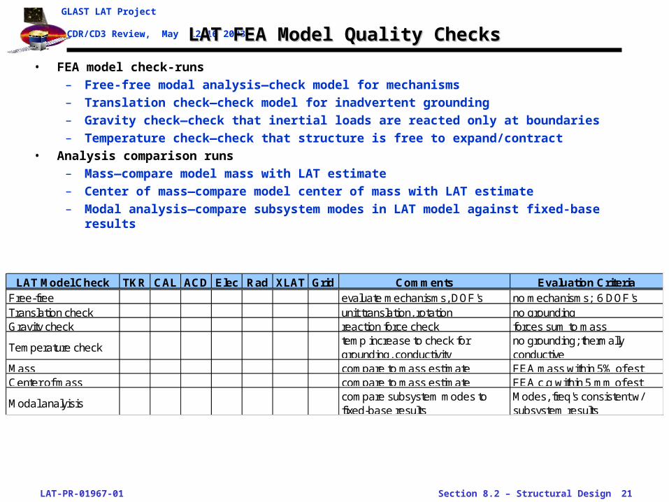
CDR/CD3 Review, May 12-16 2003LAT FEA Model Quality ChecksLAT FEA Model Quality Checks
• FEA model check-runs
– Free-free modal analysis—check model for mechanisms
– Translation check—check model for inadvertent grounding
– Gravity check—check that inertial loads are reacted only at boundaries
– Temperature check—check that structure is free to expand/contract
• Analysis comparison runs
– Mass—compare model mass with LAT estimate
– Center of mass—compare model center of mass with LAT estimate
– Modal analysis—compare subsystem modes in LAT model against fixed-base results
LAT Model Check TKR CAL ACD Elec Rad XLAT Grid Comments Evaluation CriteriaFree-free evaluate mechanisms, DOF's no mechanisms; 6 DOF'sTranslation check unit translation, rotation no groundingGravity check reaction force check forces sum to mass
Temperature checktemp increase to check for grounding, conductivity
no grounding; thermally conductive
Mass compare to mass estimate FEA mass within 5% of estCenter of mass compare to mass estimate FEA c.g within 5 mm of est
Modal analyisiscompare subsystem modes to fixed-base results
Modes, freq's consistent w/ subsystem results
LAT-PR-01967-01 Section 8.2 – Structural Design 22
GLAST LAT Project
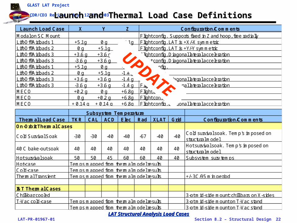
CDR/CD3 Review, May 12-16 2003Launch and Thermal Load Case DefinitionsLaunch and Thermal Load Case Definitions
LAT Structural Analysis Load CasesLAT Structural Analysis Load Cases
Launch Load Case X Y Z Configuration/Comments
Modal on SC Mount Flight config. Supports fixed in Z and hoop, free radiallyLift-Off/Airloads 1 +5.1g 0 g +4.1g Flight config. LAT is +X/-X symmetricLift-Off/Airloads 2 0 g +5.1g +4.1g Flight config. LAT is +Y/-Y symmetricLift-Off/Airloads 3 +3.6 g +3.6 g +4.1 g Flight config. Diagonal lateral accelerationLift-Off/Airloads 3 -3.6 g +3.6 g +4.1 g Flight config. Diagonal lateral accelerationLift-Off/Airloads 1 +5.1g 0 g -1.4 g Flight config. Lift-Off/Airloads 2 0 g +5.1g -1.4 g Flight config. Lift-Off/Airloads 3 +3.6 g +3.6 g -1.4 g Flight config. Diagonal lateral accelerationLift-Off/Airloads 3 -3.6 g +3.6 g -1.4 g Flight config. Diagonal lateral accelerationMECO +0.2 g 0 g +6.8g Flight config. MECO 0 g +0.2 g +6.8g Flight config. MECO + 0.14 g + 0.14 g +6.8g Flight config. Diagonal lateral acceleration
UPDATESubsystem Temperature
Thermal Load Case TKR CAL ACD Elec Rad XLAT Grid Configuration/CommentsOn-Orbit Thermal Cases
Cold Survival Soak -30 -30 -40 -40 -67 -40 -40Cold survival soak. Temp's imposed on structural model
40 C bake-out soak 40 40 40 40 40 40 40Hot survival soak. Temp's imposed on structural model
Hot survival soak 50 50 45 60 60 40 40 Subsystem surv tempsHot-case Temps mapped from thermal model resultsCold-case Temps mapped from thermal model resultsThermal Transient Temps mapped from thermal model results +/- 3C/95 min period
I&T Thermal CasesChill-bar cooled 3-pt mid-side mount; chill bars on X-sidesT-Vac cold-case Temps mapped from thermal model results 3-pt mid-side mount on T-Vac stand
Temps mapped from thermal model results 3-pt mid-side mount on T-Vac stand
LAT-PR-01967-01 Section 8.2 – Structural Design 23
GLAST LAT Project
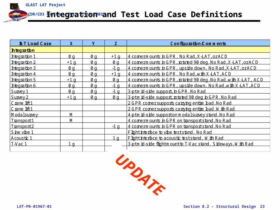
CDR/CD3 Review, May 12-16 2003Integration and Test Load Case DefinitionsIntegration and Test Load Case Definitions
I&T Load Case X Y Z Configuration/Comments
IntegrationIntegration 1 0 g 0 g +1 g 4 corner mounts in GPR. No Rad, X-LAT, or ACDIntegration 2 +1 g 0 g 0 g 4 corner mounts in GPR, rotated 90 deg. No Rad, X-LAT, or ACDIntegration 3 0 g 0 g -1 g 4 corner mounts in GPR, upside down. No Rad, X-LAT, or ACDIntegration 4 0 g 0 g +1 g 4 corner mounts in GPR. No Rad, with X-LAT, ACDIntegration 5 +1 g 0 g 0 g 4 corner mounts in GPR, rotated 90 deg. No Rad, with X-LAT, ACDIntegration 6 0 g 0 g -1 g 4 corner mounts in GPR, upside down. No Rad, with X-LAT, ACDSurvey 1 0 g 0 g -1 g 3-pt mid-side support, in GPR. No RadSurvey 2 +1 g 0 g 0 g 3-pt mid-side support, rotated 90 deg in GPR. No RadCrane lift 1 2 GPR corner supports carrying entire load. No RadCrane lift 1 2 GPR corner supports carrying entire load. With RadModal survey M 4-pt mid-side support on modal survey stand. No RadTransport 1 M 4 corner mounts in GPR on transport stand. No RadTransport 2 -1 g 4 corner mounts in GPR on transport stand. No RadSine vibe 1 Flight interface to vibe test stand. No RadAcoustic 1 1 g Flight interface to acoustic test stand. With RadT-Vac 1 1 g 3-pt mid-side flight mount to T-Vac stand. Sideways. With Rad
UPDATE
LAT-PR-01967-01 Section 8.2 – Structural Design 24
GLAST LAT Project
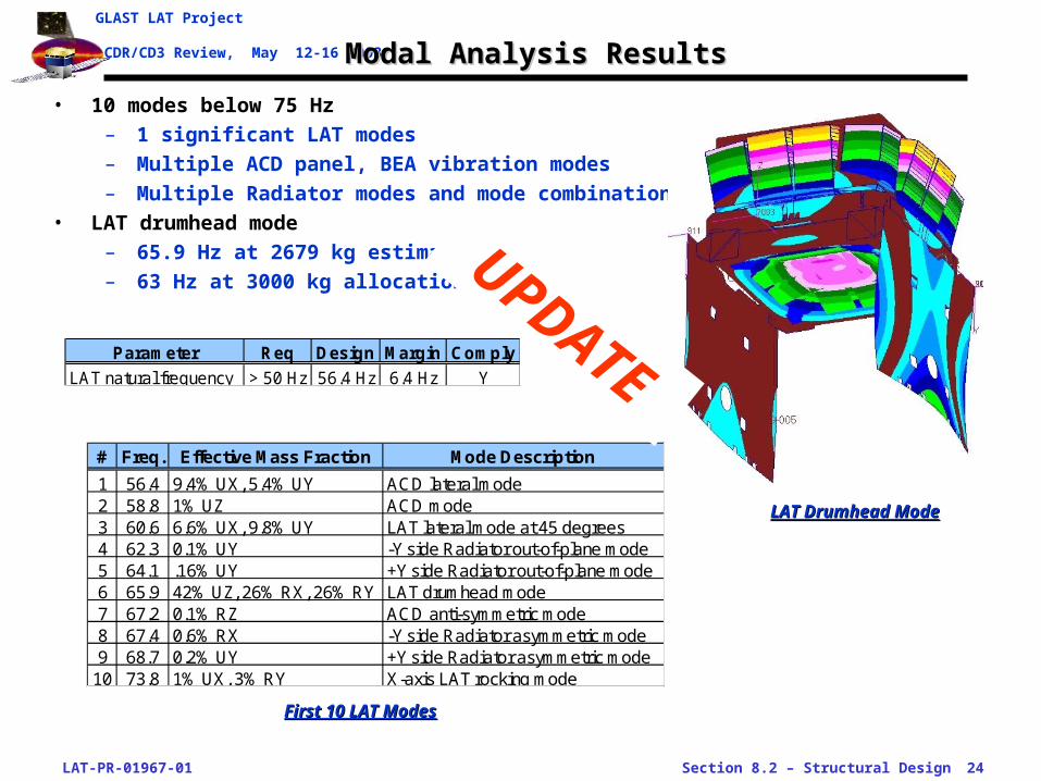
CDR/CD3 Review, May 12-16 2003 Modal Analysis ResultsModal Analysis Results
• 10 modes below 75 Hz
– 1 significant LAT modes
– Multiple ACD panel, BEA vibration modes
– Multiple Radiator modes and mode combinations
• LAT drumhead mode
– 65.9 Hz at 2679 kg estimate
– 63 Hz at 3000 kg allocation
First 10 LAT ModesFirst 10 LAT Modes
LAT Drumhead ModeLAT Drumhead Mode
# Freq. Effective Mass Fraction Mode Description
1 56.4 9.4% UX, 5.4% UY ACD lateral mode2 58.8 1% UZ ACD mode3 60.6 6.6% UX, 9.8% UY LAT lateral mode at 45 degrees4 62.3 0.1% UY -Y side Radiator out-of-plane mode5 64.1 .16% UY +Y side Radiator out-of-plane mode6 65.9 42% UZ, 26% RX, 26% RY LAT drumhead mode7 67.2 0.1% RZ ACD anti-symmetric mode8 67.4 0.6% RX -Y side Radiator asymmetric mode9 68.7 0.2% UY +Y side Radiator asymmetric mode
10 73.8 1% UX, 3% RY X-axis LAT rocking mode
Parameter Req Design Margin Comply
LAT natural frequency > 50 Hz 56.4 Hz 6.4 Hz Y
UPDATE
LAT-PR-01967-01 Section 8.2 – Structural Design 25
GLAST LAT Project
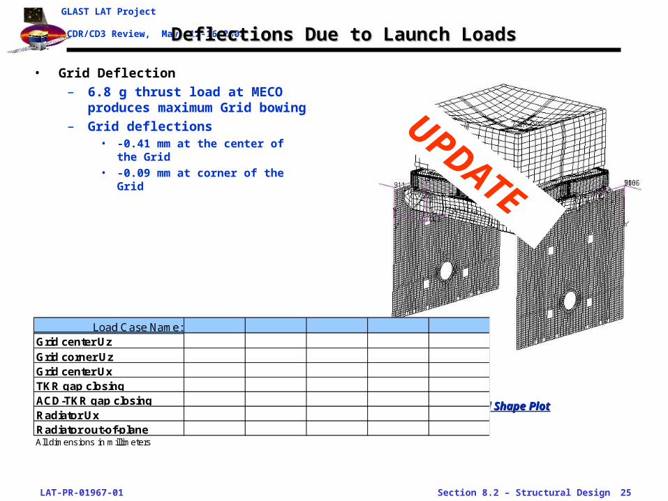
CDR/CD3 Review, May 12-16 2003Deflections Due to Launch LoadsDeflections Due to Launch Loads
• Grid Deflection
– 6.8 g thrust load at MECO produces maximum Grid bowing
– Grid deflections• -0.41 mm at the center of the Grid• -0.09 mm at corner of the Grid
LAT Deflected Shape PlotLAT Deflected Shape Plot
UPDATE
Load Case Name:Grid center UzGrid corner UzGrid center UxTKR gap closingACD-TKR gap closingRadiator UxRadiator out-of-planeAll dimensions in millimeters
LAT-PR-01967-01 Section 8.2 – Structural Design 26
GLAST LAT Project
CDR/CD3 Review, May 12-16 2003 Interface Load RecoveryInterface Load Recovery
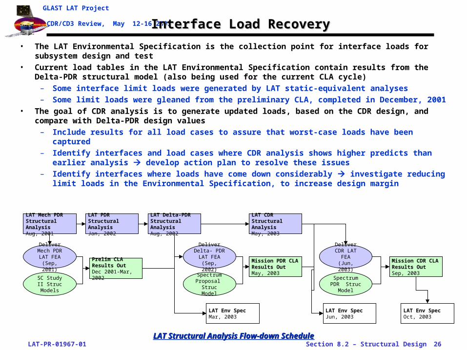
• The LAT Environmental Specification is the collection point for interface loads for subsystem design and test
• Current load tables in the LAT Environmental Specification contain results from the Delta-PDR structural model (also being used for the current CLA cycle)
– Some interface limit loads were generated by LAT static-equivalent analyses
– Some limit loads were gleaned from the preliminary CLA, completed in December, 2001
• The goal of CDR analysis is to generate updated loads, based on the CDR design, and compare with Delta-PDR design values
– Include results for all load cases to assure that worst-case loads have been captured
– Identify interfaces and load cases where CDR analysis shows higher predicts than earlier analysis develop action plan to resolve these issues
– Identify interfaces where loads have come down considerably investigate reducing limit loads in the Environmental Specification, to increase design margin
LAT Mech PDR Structural AnalysisAug, 2001
LAT PDR Structural AnalysisJan, 2002
Prelim CLA Results OutDec 2001-Mar, 2002
Deliver Mech PDR LAT FEA (Sep,
2001)
LAT Delta-PDR Structural AnalysisAug, 2002
Deliver Delta- PDR LAT FEA (Sep,
2002)
LAT CDR Structural AnalysisMay, 2003
LAT Env SpecMar, 2003
SC Study II Struc Models
Deliver CDR LAT FEA
(Jun, 2003)
Spectrum Proposal
Struc Model
Mission PDR CLA Results OutMay, 2003
LAT Env SpecJun, 2003
Spectrum PDR Struc
Model
Mission CDR CLA Results OutSep, 2003
LAT Env SpecOct, 2003
LAT Structural Analysis Flow-down ScheduleLAT Structural Analysis Flow-down Schedule

LAT-PR-01967-01 Section 8.2 – Structural Design 27
GLAST LAT Project
CDR/CD3 Review, May 12-16 2003TKR Interface Load RecoveryTKR Interface Load Recovery
• TKR Flexure joint
– Flexures isolate the carbon-fiber TKR structure from thermal strains of the Grid
– All flexure normals point to the center of a TKR module
– The 8 flexures are not a kinematic mount
• TKR Flexure force recovery
– Nodal forces are retrieved by isolating nodal forces at the TKR Flexure beam elements
– All forces are expressed in local cylindrical coordinates, with the module centerline the z axis
– Shear forces in theta-increasingdirection have the same sign. Shear forces sum to zero.
– Design limit loads are the maximaof the TKR module loads
• Limit loads identified for peakcompressive, tensile, and shear load
• Peak loads all occur in corner bays
TKR-Grid Flexures Design Accept Qual Unit
Launch EventLift-Off/
TransonicMECO
Mid-Side FlexuresShear 2266 2061 2266 2832.5 NTension/Compress. 391 291 391 489 N
Corner FlexuresShear 1,003 80 1,003 1,254 NTension/Compress. 1,277 1,193 1,277 1,596 N
Source (2) (4)
Flexure Limit LoadsFlexure Limit LoadsDelta PDR Analysis ModelDelta PDR Analysis Model
Source: LAT-SS-00778-01 “LAT Environmental Specification,” March 2003
UPDATE
LAT-PR-01967-01 Section 8.2 – Structural Design 28
GLAST LAT Project
CDR/CD3 Review, May 12-16 2003CAL Interface Load RecoveryCAL Interface Load Recovery
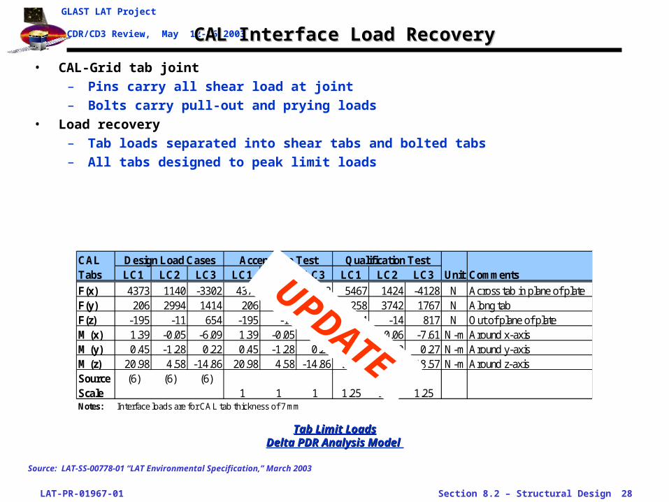
• CAL-Grid tab joint
– Pins carry all shear load at joint
– Bolts carry pull-out and prying loads
• Load recovery
– Tab loads separated into shear tabs and bolted tabs
– All tabs designed to peak limit loads
Tab Limit LoadsTab Limit LoadsDelta PDR Analysis Model Delta PDR Analysis Model
Source: LAT-SS-00778-01 “LAT Environmental Specification,” March 2003
CAL Design Load Cases Acceptance Test Qualification TestTabs LC1 LC2 LC3 LC1 LC2 LC3 LC1 LC2 LC3 Unit Comments
F(x) 4373 1140 -3302 4373 1140 -3302 5467 1424 -4128 N Across tab in plane of plateF(y) 206 2994 1414 206 2994 1414 258 3742 1767 N Along tabF(z) -195 -11 654 -195 -11 654 -244 -14 817 N Out of plane of plateM(x) 1.39 -0.05 -6.09 1.39 -0.05 -6.09 1.74 -0.06 -7.61 N-m Around x-axisM(y) 0.45 -1.28 0.22 0.45 -1.28 0.22 0.56 -1.60 0.27 N-m Around y-axisM(z) 20.98 4.58 -14.86 20.98 4.58 -14.86 26.22 5.73 -18.57 N-m Around z-axisSource (6) (6) (6)Scale 1 1 1 1.25 1.25 1.25Notes: Interface loads are for CAL tab thickness of 7 mm
UPDATE

LAT-PR-01967-01 Section 8.2 – Structural Design 29
GLAST LAT Project
CDR/CD3 Review, May 12-16 2003ACD Interface Load RecoveryACD Interface Load Recovery
• ACD Base Electronics Assembly (BEA) to Grid Joint
– Bolted connection at 4 corners of BEA carry z-direction (thrust) loads only
– Bolted and pinned connections at the center of each of the 4 sides
• Interface load recovery
– Interface loads evaluated by retrieving nodal forces at rigid extension from Grid to BEA
– Loads shown are the maximum of predicts from ACD subsystem and LAT level analysis
ACD-Grid Mount Design Accept. PFQ Unit CommentCorner Mounts
Shear 0 0 0 N RSS of X, Y max shearTens/Compression 1787 1787 2234 N Parallel to LAT Z-axis
Mid-Side MountsShear 4402 4402 5503 N RSS of X, Z shears in plane of Grid wallTens/Compression 2223 2223 2779 N Normal to Grid wall
Source
ACD Limit LoadsACD Limit LoadsDelta PDR Analysis Model Delta PDR Analysis Model
Source: LAT-SS-00778-01 “LAT Environmental Specification,” March 2003
UPDATE

LAT-PR-01967-01 Section 8.2 – Structural Design 30
GLAST LAT Project
CDR/CD3 Review, May 12-16 2003Electronics Interface Load RecoveryElectronics Interface Load Recovery
• Electronics Box joints
– Rigid stand-offs to the CAL carry z-direction (thrust) loads, and lateral loads and moments
– Flexible connection to the X-LAT Plates allow transverse motion while providing compressive pre-load
• Interface load/deflection recovery
– Limit loads extracted from model
– Max relative motion at X-LAT Plate interface also tracked, for use in finalizing the bolted joint design
E-Box Stand-Off Design Accept. Qual UnitTension 3,750 3,750 4,688 NCompression 2,625 2,625 3,281 NShear 1,288 1,288 1,609 NBending Moment 19.3 19.3 24.1 N-m
Electronic Box Limit LoadsElectronic Box Limit LoadsDelta PDR Analysis Model Delta PDR Analysis Model
Source: LAT-SS-00778-01 “LAT Environmental Specification,” March 2003
UPDATE
LAT-PR-01967-01 Section 8.2 – Structural Design 31
GLAST LAT Project
CDR/CD3 Review, May 12-16 2003Structural Analysis Summary and Further WorkStructural Analysis Summary and Further Work
• Summary
– Subsystem structural models have been updated to reflect Peer Review designs
– First look at mode shapes and frequency show that the LAT has margin with respect to its frequency requirement
– Structural model re-work is still in process
• Further Work
– Verify subsystem model integration
– Complete all load cases with LAT CDR model
– Update subsystem interface loads, based on CDR model
– Deliver model to GLAST PO for next CLA cycle
– Incorporate acoustic analysis results into limit load analyses
– Revise “LAT Environmental Specification” with these results
– Start pre-test analysis runs• Dynamic analyses to size accelerometers• STE structural analyses
UPDATE
LAT-PR-01967-01 Section 8.2 – Structural Design 32
GLAST LAT Project
CDR/CD3 Review, May 12-16 2003 Verification Test OutlineVerification Test Outline
• Integration and Test flow
• Qualification and verification flow
– Strength qualification test flow
– Vibroacoustic test flow
• Dynamic test plans (see LAT-MD-01196, “Dynamics Test Plan”)
– Modal survey
– Sine vibration
– Sine Burst
– Acoustic
• LAT survey plans (see LAT-MD-00895, “LAT Instrument Survey Plan”)
– Optical survey
– Cosmic-ray muon survey
LAT-PR-01967-01 Section 8.2 – Structural Design 33
GLAST LAT Project
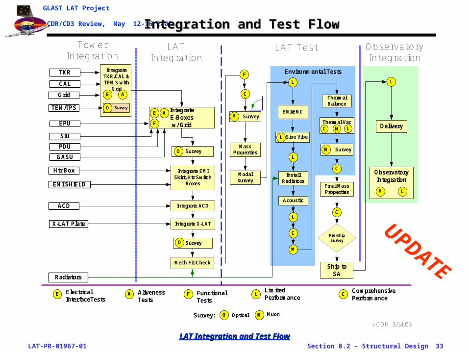
CDR/CD3 Review, May 12-16 2003 Integration and Test FlowIntegration and Test Flow
ObservatoryIntegration
Sine Vibe
TowerIntegration
LATIntegration
LAT Test ObservatoryIntegration
TKR
CAL
TEM/TPS
Grid
Radiators
EPU
SIU
GASU
PDU
ACD
IntegrateE-Boxesw/ Grid
Htr Box
Delivery
AlivenessTests
LimitedPerformance
X-LAT Plate
C
CLE A
A
MassProperties
EMI/EMC
L
InstallRadiators
Acoustic
L
C
Thermal Vac
ThermalBalance
C L
C
Final MassProperties
Pre-ShipSurvey
L
A
Ship toSA
F
F
F
EMI SHIELD
Survey Survey
M
O M
L
M
O Optical M Muon
IntegrateTKR/CAL &TEM's with
Grid
SurveyO
Integrate ACD
SurveyO
Integrate EMISkirt, Htr Switch
Boxes
Mech Fit-Check
SurveyM
Modalsurvey
E
L
FunctionalTests
Survey:
L
ElectricalInterfaceTests
ComprehensivePerformance
Environmental Tests
E
M
C
v CDR 3/14/03
Integrate X-LAT
LAT Integration and Test FlowLAT Integration and Test Flow
UPDATE
LAT-PR-01967-01 Section 8.2 – Structural Design 34
GLAST LAT Project
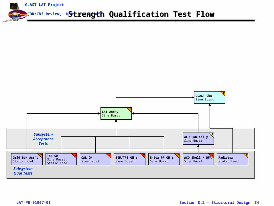
CDR/CD3 Review, May 12-16 2003Strength Qualification Test FlowStrength Qualification Test Flow
ACD Sub-Ass’ySine Burst
A
TKR QMSine Burst, Static Load
QACD Shell + BFASine Burst
QCAL QMSine Burst
QTEM/TPS QM’sSine Burst
QE-Box PF QM’sSine Burst
PGrid Box Ass’yStatic Load
PRadiatorStatic Load
P
LAT Ass’ySine Burst
P
GLAST ObsSine Burst
P
Subsystem Qual Tests
Subsystem Acceptance
Tests

LAT-PR-01967-01 Section 8.2 – Structural Design 35
GLAST LAT Project
CDR/CD3 Review, May 12-16 2003 Vibroacoustic Test FlowVibroacoustic Test Flow
• LAT and GLAST vibroacoustic test plan
– LAT modal survey—without Radiators, while at SLAC
– LAT sine vibration—without Radiators; includes sine sweep signature
– LAT acoustic—without Radiators
– GLAST Observatory sine vibration—with Radiators but without solar arrays (TBR); includes sine sweep signature
– GLAST Observatory acoustic—with Radiators but without solar arrays (TBR)
– GLAST Observatory shock—shock event applied at PAF separation plane
ACD Sub-Ass’ySine Vibe, Random Vibe
A
ACD Sub-Ass’yAcoustic
A
TKR Qual ModuleSine Vibe, Random Vibe
Q
TKR Flt ModulesSine Vibe, Random Vibe
A
ACD Shell + BFASine Vibe, Random Vibe
Q
ACD Shell + BFAAcoustic
Q
CAL QM’sSine Vibe, Random Vibe
Q
CAL FM’sRandom Vibe
A
TEM/TPS QM’sSine Vibe, Random Vibe
Q
TEM/TPS FM’sRandom Vibe
A
E-Box PF QM’sSine Vibe, Random Vibe
P
Grid Box Ass’y
P
RadiatorSine Vibe
P
RadiatorAcoustic
P
LAT Ass’yModal Survey, Sine Vibe
P
LAT Ass’yAcoustic
PGLAST ObsSine Vibe
PGLAST ObsAcoustic
P
Subsystem Qual Tests
Subsystem Acceptance
Tests
GLAST ObsShock
P

LAT-PR-01967-01 Section 8.2 – Structural Design 36
GLAST LAT Project
CDR/CD3 Review, May 12-16 2003 LAT Modal SurveyLAT Modal Survey
• Test goals
– Validate the LAT structural finite element analysis (FEA) model by correlating with test results
– Measure all primary modes of the LAT/Grid structure.
– Measure the first mode, and all modes predicted to have high mass participation, for every subsystem
– Measure as many natural frequencies of the LAT up to 150 Hz as practical
– Test results will be used to evaluate the predicted expected modal frequencies and mode shapes, and used to modify the structural FEA, if needed.
– Finalize test environments and notching plans for sine vibration testing
• Configuration
– Fully integrated, except the Radiators are not mounted
– Supported off of its spacecraft (SC) mount brackets,
– +Z-axis point vertically up
– LAT powered off during testing
• Specialized test equipment requirements
– LAT supported by the Vibe Test Plate which provides a rigid support of each mount point
– Vibe Test Plate sits on a massive base-isolated table, to damp high-frequency base noise being transmitted to the structure
– Excited using two stingers, located under the LAT
LAT-PR-01967-01 Section 8.2 – Structural Design 37
GLAST LAT Project
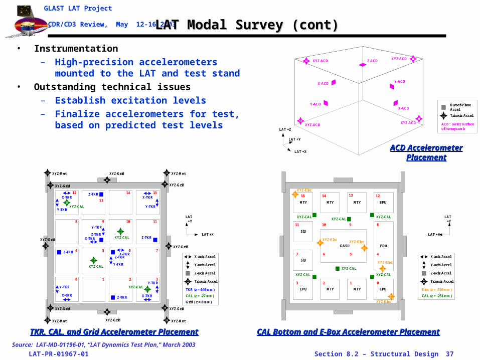
CDR/CD3 Review, May 12-16 2003 LAT Modal Survey (cont)LAT Modal Survey (cont)
• Instrumentation
– High-precision accelerometers mounted to the LAT and test stand
• Outstanding technical issues
– Establish excitation levels
– Finalize accelerometers for test, based on predicted test levels
LAT +X
LAT+Y
TKR (z = 640 mm)
CAL (z = -27 mm)
X-TKR
Y-TKR
Grid ( z = 0 mm)
X-TKR
X-TKR X-TKR
XYZ-CAL
XYZ-CAL
XYZ-CAL
XYZ-CAL
Z-TKR
Z-TKR
Z-TKR
Z-TKR
Z-TKR
Z-TKR
0 1 2 3
4
Y-TKR
Y-TKR
Y-TKR
Y-TKR
765
1098
1514
13
12
11
XYZ-Grid
XYZ-Grid
XYZ-Grid
XYZ-Grid
XYZ-Grid
XYZ-GridXYZ-Grid
XYZ-Grid
XYZ-Mnt XYZ-Mnt
XYZ-MntXYZ-Mnt
Y-TKR
X-TKR
X-TKR
X-axis Accel
Y-axis Accel
Tri-axis Accel
Z-axis Accel
Source: LAT-MD-01196-01, “LAT Dynamics Test Plan,” March 2003
LAT +Y
LAT +Z
ACD: outer surfaceof honeycomb
Tri-axis Accel
Out-of-PlaneAccel
LAT +X
Y-ACD
Z-ACD
X-ACD
Y-ACD
XYZ-ACD
XYZ-ACDXYZ-ACD
XYZ-ACD
X-ACD
LAT +X
LAT+Y
Elec (z = -500 mm)
CAL (z = -251 mm)
0123
47 6 5
10 9 8
15 14 13 12
11
X-axis Accel
Y-axis Accel
Tri-axis Accel
Z-axis Accel
PDU
SIU
SIU
EPU EPU
EPUMTY MTY MTY
MTY MTY
GASU
XYZ-CALXYZ-CAL
XYZ-CAL
XYZ-CAL
XYZ-CAL
XYZ-CAL
XYZ-Elec
XYZ-Elec
XYZ-Elec
XYZ-Elec
XYZ-Elec
ACD Accelerometer ACD Accelerometer PlacementPlacement
CAL Bottom and E-Box Accelerometer PlacementCAL Bottom and E-Box Accelerometer PlacementTKR, CAL, and Grid Accelerometer PlacementTKR, CAL, and Grid Accelerometer Placement

LAT-PR-01967-01 Section 8.2 – Structural Design 38
GLAST LAT Project
CDR/CD3 Review, May 12-16 2003 LAT Sine Vibration TestLAT Sine Vibration Test
• Test goals
– Verify the LAT’s ability to survive the low frequency launch environment
– Test for workmanship on hardware such as wiring harnesses, MLI, and cable support and strain-reliefs which will not have been fully verified at the subsystem level
– Interface verification test for subsystem structural interfaces to the LAT Grid
• Configuration
– Fully integrated, except the Radiators are not installed
– Supported off of its spacecraft (SC) mount brackets, on the Vibration Test Stand
– The LAT is tested in all three axes, X, Y, and Z independently, requiring re-configuration between tests
– The LAT is powered off during sinusoidal vibration testing, and the E-GSE cable harnesses removed
• Specialized test equipment requirements
– The Vibe Test Stand must support the LAT at the SC interface with flight-like connections
– The Stand must allow for reconfiguration to alternate axes, with the LAT attached, to avoid unnecessary handling

LAT-PR-01967-01 Section 8.2 – Structural Design 39
GLAST LAT Project
CDR/CD3 Review, May 12-16 2003LAT Sine Vibration Test (cont)LAT Sine Vibration Test (cont)
• Instrumentation
– Accelerometers mounted to the LAT and test stand, to cover the entire dynamic range predicted for the LAT and subsystems
• Outstanding technical issues
– Accelerometer sensitivity—pre-test dynamic analysis will indicate the level of precision and dynamic range needed for this test
– Finalize LAT degrees of freedom at STE connection (simulating a “fixed” connection or a flexure)
– Establish test levels based on Observatory CLA, without exceeding interface limit loads
LAT +X
LAT+Y
TKR (z = 640 mm)
CAL (z = -27 mm)
Grid ( z = 0 mm)
XYZ-CAL
XYZ-CAL
XYZ-CAL
XYZ-CAL
XYZ-TKR
0 1 2 3
4 765
1098
15141312
11
XYZ-Grid
XYZ-Grid
XYZ-Grid
XYZ-Grid
XYZ-Grid
XYZ-GridXYZ-Grid
XYZ-Grid
XYZ-Mnt XYZ-Mnt
XYZ-MntXYZ-Mnt
X-axis Accel
Y-axis Accel
Tri-axis Accel
Z-axis Accel
XYZ-TKRXYZ-TKR XYZ-TKR XYZ-TKR
XYZ-TKR XYZ-TKR XYZ-TKR
XYZ-TKR XYZ-TKR XYZ-TKR
XYZ-TKR XYZ-TKR XYZ-TKRXYZ-TKR
LAT +X
LAT +Z
Radiator Inner Facesheet
Tri-axis Accel
Y-axis Accel
Source: LAT-MD-01196-01, “LAT Dynamics Test Plan,” March 2003
TKR, CAL, and Grid Accelerometer PlacementTKR, CAL, and Grid Accelerometer Placement
Radiators Accelerometer PlacementRadiators Accelerometer Placement
Qualification Sine Vibration Test LevelsAxis Freq. (Hz) Test levels Sweep Rate
Thrust 5 to 7.4 1.27 cm (0.5 in.) double amplitude 2 octaves/min7.4 to 50 1.4 g (zero to peak)
Lateral 5 to 6.2 1.27 cm (0.5 in.) double amplitude 2 octaves/min6.2 to 50 1.0 g (zero to peak)
LAT Sine Vibration Minimum Test LevelsLAT Sine Vibration Minimum Test Levels

LAT-PR-01967-01 Section 8.2 – Structural Design 40
GLAST LAT Project
CDR/CD3 Review, May 12-16 2003 LAT Sine Burst TestLAT Sine Burst Test
• Test goals
– Complete qualification of the LAT interface to the SC, and surrounding regions
• Configuration
– Same configuration as the sine vibe test
• Specialized test equipment requirements
– Same requirements as the sine vibe test
• Instrumentation
– Same instrumentation as the sine vibe test
• Outstanding technical issues
– Establish test levels with pre-test analysis, to develop proto-qual level interface loads
LAT-PR-01967-01 Section 8.2 – Structural Design 41
GLAST LAT Project
CDR/CD3 Review, May 12-16 2003 LAT Acoustic TestLAT Acoustic Test
• Test goals
– Verify the LAT’s ability to survive the acoustic launch environment
– Test for workmanship on LAT hardware, especially that hardware which responds to acoustic loading
– Validate the acoustic analysis
• Configuration
– LAT is fully integrated, including the Radiators
– Mounted to STE using the flight-configuration bolted joint
– LAT +Z-axis vertical, and with Radiators integrated to the Grid as well as to the STE at the SC strut mount points
– LAT is powered off during acoustic testing, and the E-GSE cable harnesses removed
• Specialized test equipment requirements
– The Vibe Test Stand must support the LAT in the same degrees of freedom as the SC flexures, to avoid over-constraining the Grid and Radiators
– The STE fills the volume between the Radiators, so must approximate the acoustic behavior of the SC
• Instrumentation
– Accelerometers mounted to the LAT and test stand
– Microphones mounted around the LAT
LAT-PR-01967-01 Section 8.2 – Structural Design 42
GLAST LAT Project
CDR/CD3 Review, May 12-16 2003 LAT Acoustic Test (cont)LAT Acoustic Test (cont)
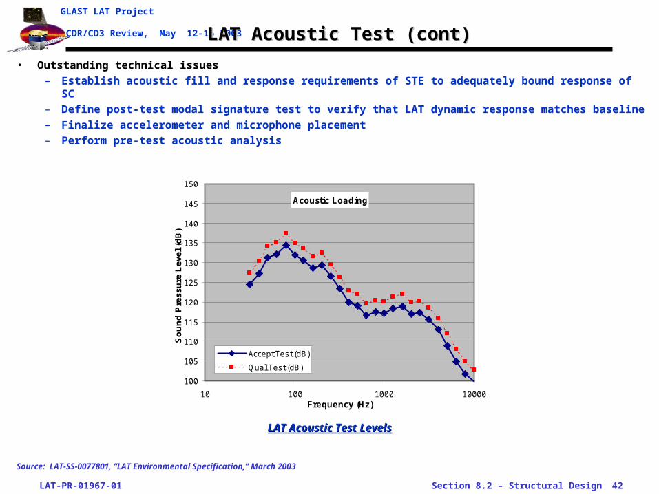
• Outstanding technical issues
– Establish acoustic fill and response requirements of STE to adequately bound response of SC
– Define post-test modal signature test to verify that LAT dynamic response matches baseline
– Finalize accelerometer and microphone placement
– Perform pre-test acoustic analysis
Acoustic Loading
100
105
110
115
120
125
130
135
140
145
150
10 100 1000 10000Frequency (Hz)
So
un
d P
ress
ure
Lev
el (
dB
)
Accept Tes t (dB)
Qual Tes t (dB)
LAT Acoustic Test LevelsLAT Acoustic Test Levels
Source: LAT-SS-0077801, “LAT Environmental Specification,” March 2003

LAT-PR-01967-01 Section 8.2 – Structural Design 43
GLAST LAT Project
CDR/CD3 Review, May 12-16 2003 LAT SurveyingLAT Surveying
• Survey program goals
– Verify as-integrated interface stay-clears
– Verify LAT alignment requirements
– Verify science performance requirements • Validate analytical thermal-mechanical analysis models• Develop correlation functions for thermal-mechanical distortion• Predict the expected on-orbit precision of the instrument
• Survey program description
– Optical surveying• Subsystem inspection measures position of survey retro-reflector balls with respect to physical
features and active elements of subsystem module• After integration, laser tracker measures bearing and distances to balls on the LAT and in the
integration room• Data reduction of measurements produces position location information for all balls relative to
room coordinate system, and prediction of measurement precision• This will establish location of subsystem surfaces and features in their as-integrated positions,
providing a verification check during integration
– Muon surveying• Uses naturally-occurring cosmic-ray muons• Muons generate straight-line tracks through TKR modules• Mis-alignments between modules will show up as a step in the reconstructed track• With muons generating enough cross-tower tracks, the relative locations of tower can be
measured• This will be used to precisely establish the locations and attitudes (and changes) of TKR modules

LAT-PR-01967-01 Section 8.2 – Structural Design 44
GLAST LAT Project
CDR/CD3 Review, May 12-16 2003 LAT Surveying (cont 1)LAT Surveying (cont 1)
1A: 1-Toweroptical survey
Integrate Towers Int. ACD Ship/Vibe T-Bal/T-Vac
1B: 4-Toweroptical survey
2A,B,C: LAT baselinemuon survey
1C: 16-Toweroptical/muon survey
3A: Pre-T-Vacmuon survey
4A,B,C: T-Vac muonsurvey at temp
# Goal When/Where Orient. Method Support/Configuration Cooling Temp
1AVerify SS stayclears, TKR alignment accuracy
SLAC, after 1st TKR module is integrated
+Z Up Optical4 corners on GPR; 1 TKR/CAL/ TEM tower integrated. LAT off
None RT
1BVerify SS stayclears, TKR alignment accuracy
SLAC, after 4 TKR modules are integrated
+Z Up Optical4 corners on GPR; 4 TKR/CAL/ TEM towers integrated. LAT off
None RT
1CVerify SS stayclears; establish baseline position of all TKR's
SLAC, before ACD integration
+Z HorizOptical/
Muon3 mid-sides on GPR; ACD not on LAT on. Push on 4th mid-side.
Elec: forced air; Det: conduction
17 C
2A Verify ACD stay-clearsSLAC, after ACD and X-LAT Plate integration
+Z Up Optical4-corners on GPR; ACD integrated. LAT off.
None RT
2BEstablish baseline position of TKR's with ACD on
SLAC, after CPT +Z Horiz Muon 3 mid-sides on GPRElec: forced air; Det: conduction
17 C
2CCharacterize gravity effect on TKR position w/ ACD
SLAC, after CPT +Z Up Muon 3 mid-sides on GPRElec: forced air; Det: conduction
17 C
3ARe-baseline TKR positions after transport, vibe
NRL, after vibe and before T-Vac pump-down
+Z Horiz Muon 3 mid-sides on T-Vac STEElec: forced air; Det: conduction
17 C
4ACharacterize thermal effects on LAT at min temp
NRL T-Vac Chamber +Z Horiz Muon 3 mid-sides on T-Vac STEElec: X-LAT Pl, Det: conduction
-5 C
4BEstablish baseline position of TKR's at nom operating temp
NRL T-Vac Chamber +Z Horiz Muon 3 mid-sides on T-Vac STEElec: X-LAT Pl, Det: conduction
8 C
4CCharacterize thermal effects on LAT at max temp
NRL T-Vac Chamber +Z Horiz Muon 3 mid-sides on T-Vac STEElec: X-LAT Pl, Det: conduction
17 C
LAT Optical and Muon Surveys During Integration and TestLAT Optical and Muon Surveys During Integration and Test
Source: LAT-MD-00895 “LAT Instrument Survey Plan”
LAT-PR-01967-01 Section 8.2 – Structural Design 45
GLAST LAT Project
CDR/CD3 Review, May 12-16 2003 LAT Surveying (cont 2)LAT Surveying (cont 2)
• Instrumentation
– Laser tracker—measurement precision of instrument is less than 10 microns, but actual precision is more a function of room temperature stability, reflector ball location precision
– Tracker—measurement precision and instrument calibration will be verified with Calibration Unit beam tests at SLAC
• Specialized test equipment requirements
– Room temperature controlled to within 5 oC (TBR)
– LAT and GSE/STE temperature stable to within 2 oC (TBR)
– Support stands allow for leveling the LAT to within 0.2 degrees to ensure proper functioning of heat pipes
– Chill plates provide a heat sink for the Grid during in-air testing
• Outstanding technical issues
– Investigating the use of inclinometers during thermal-vacuum testing
– Thermal-mechanical model of LAT in test configuration has not yet been done—this is needed to establish precision and stability requirements for STE
LAT-PR-01967-01 Section 8.2 – Structural Design 46
GLAST LAT Project
CDR/CD3 Review, May 12-16 2003Summary of Structural Test Issues and Closure PlansSummary of Structural Test Issues and Closure Plans
LAT-PR-01967-01 Section 8.2 – Structural Design 47
GLAST LAT Project
CDR/CD3 Review, May 12-16 2003 Summary and ConclusionsSummary and Conclusions
• UPDATE
• Structural Analysis Summary
• Verification Test Summary
• Conclusions
• Summary
– LAT Dynamics Test Plan has been written and is ready for initial release
– LAT Thermal Test Plan has been written and is ready for initial release
– LAT Survey Plan has been written, with final pieces coming together for release before CDR
– Test instrumentation and levels are understood
• Further work
– Perform pre-test analysis to finalize instrumentation and STE requirements
– Expand test plans with results of pre-test analysis
– Complete test implementation plans


