
15705 (supercedes 5646)-1114-S5
TCC-500Link‐Belt Cranes
Technical DataSpecifications & Capacities
Telescopic Crawler Crane50 Ton (51mt Export Machine)
CAUTION: This material is supplied for reference useonly. Operator must refer to in-cab Crane RatingManual and Operator's Manual to determineallowable crane lifting capacities and assembly andoperating procedures.

5705 (supercedes 5646)-1114-S5
TCC-500 Link‐Belt Cranes
5705 (supercedes 5646)-1114-S5
TCC-500Link‐Belt Cranes
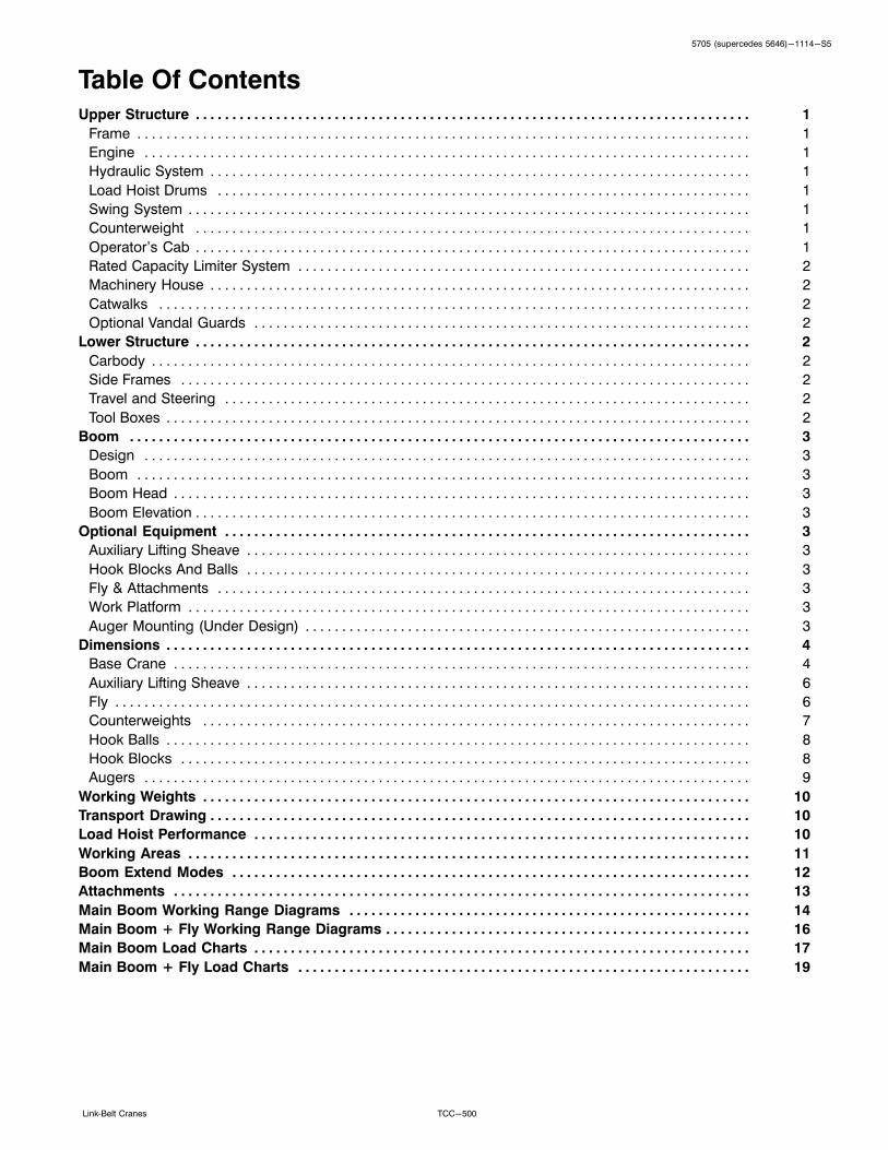
Table Of ContentsUpper Structure 1. . . . . . . . . . . . . . . . . . . . . . . . . . . . . . . . . . . . . . . . . . . . . . . . . . . . . . . . . . . . . . . . . . . . . . . . . . . .
Frame 1. . . . . . . . . . . . . . . . . . . . . . . . . . . . . . . . . . . . . . . . . . . . . . . . . . . . . . . . . . . . . . . . . . . . . . . . . . . . . . . . . . . .
Engine 1. . . . . . . . . . . . . . . . . . . . . . . . . . . . . . . . . . . . . . . . . . . . . . . . . . . . . . . . . . . . . . . . . . . . . . . . . . . . . . . . . . .
Hydraulic System 1. . . . . . . . . . . . . . . . . . . . . . . . . . . . . . . . . . . . . . . . . . . . . . . . . . . . . . . . . . . . . . . . . . . . . . . . . .
Load Hoist Drums 1. . . . . . . . . . . . . . . . . . . . . . . . . . . . . . . . . . . . . . . . . . . . . . . . . . . . . . . . . . . . . . . . . . . . . . . . .
Swing System 1. . . . . . . . . . . . . . . . . . . . . . . . . . . . . . . . . . . . . . . . . . . . . . . . . . . . . . . . . . . . . . . . . . . . . . . . . . . . .
Counterweight 1. . . . . . . . . . . . . . . . . . . . . . . . . . . . . . . . . . . . . . . . . . . . . . . . . . . . . . . . . . . . . . . . . . . . . . . . . . . .
Operator's Cab 1. . . . . . . . . . . . . . . . . . . . . . . . . . . . . . . . . . . . . . . . . . . . . . . . . . . . . . . . . . . . . . . . . . . . . . . . . . . .
Rated Capacity Limiter System 2. . . . . . . . . . . . . . . . . . . . . . . . . . . . . . . . . . . . . . . . . . . . . . . . . . . . . . . . . . . . . .
Machinery House 2. . . . . . . . . . . . . . . . . . . . . . . . . . . . . . . . . . . . . . . . . . . . . . . . . . . . . . . . . . . . . . . . . . . . . . . . . .
Catwalks 2. . . . . . . . . . . . . . . . . . . . . . . . . . . . . . . . . . . . . . . . . . . . . . . . . . . . . . . . . . . . . . . . . . . . . . . . . . . . . . . . .
Optional Vandal Guards 2. . . . . . . . . . . . . . . . . . . . . . . . . . . . . . . . . . . . . . . . . . . . . . . . . . . . . . . . . . . . . . . . . . . .
Lower Structure 2. . . . . . . . . . . . . . . . . . . . . . . . . . . . . . . . . . . . . . . . . . . . . . . . . . . . . . . . . . . . . . . . . . . . . . . . . . . .
Carbody 2. . . . . . . . . . . . . . . . . . . . . . . . . . . . . . . . . . . . . . . . . . . . . . . . . . . . . . . . . . . . . . . . . . . . . . . . . . . . . . . . . .
Side Frames 2. . . . . . . . . . . . . . . . . . . . . . . . . . . . . . . . . . . . . . . . . . . . . . . . . . . . . . . . . . . . . . . . . . . . . . . . . . . . . .
Travel and Steering 2. . . . . . . . . . . . . . . . . . . . . . . . . . . . . . . . . . . . . . . . . . . . . . . . . . . . . . . . . . . . . . . . . . . . . . . .
Tool Boxes 2. . . . . . . . . . . . . . . . . . . . . . . . . . . . . . . . . . . . . . . . . . . . . . . . . . . . . . . . . . . . . . . . . . . . . . . . . . . . . . . .
Boom 3. . . . . . . . . . . . . . . . . . . . . . . . . . . . . . . . . . . . . . . . . . . . . . . . . . . . . . . . . . . . . . . . . . . . . . . . . . . . . . . . . . . . .
Design 3. . . . . . . . . . . . . . . . . . . . . . . . . . . . . . . . . . . . . . . . . . . . . . . . . . . . . . . . . . . . . . . . . . . . . . . . . . . . . . . . . . .
Boom 3. . . . . . . . . . . . . . . . . . . . . . . . . . . . . . . . . . . . . . . . . . . . . . . . . . . . . . . . . . . . . . . . . . . . . . . . . . . . . . . . . . . .
Boom Head 3. . . . . . . . . . . . . . . . . . . . . . . . . . . . . . . . . . . . . . . . . . . . . . . . . . . . . . . . . . . . . . . . . . . . . . . . . . . . . . .
Boom Elevation 3. . . . . . . . . . . . . . . . . . . . . . . . . . . . . . . . . . . . . . . . . . . . . . . . . . . . . . . . . . . . . . . . . . . . . . . . . . . .
Optional Equipment 3. . . . . . . . . . . . . . . . . . . . . . . . . . . . . . . . . . . . . . . . . . . . . . . . . . . . . . . . . . . . . . . . . . . . . . . .
Auxiliary Lifting Sheave 3. . . . . . . . . . . . . . . . . . . . . . . . . . . . . . . . . . . . . . . . . . . . . . . . . . . . . . . . . . . . . . . . . . . . .
Hook Blocks And Balls 3. . . . . . . . . . . . . . . . . . . . . . . . . . . . . . . . . . . . . . . . . . . . . . . . . . . . . . . . . . . . . . . . . . . . .
Fly & Attachments 3. . . . . . . . . . . . . . . . . . . . . . . . . . . . . . . . . . . . . . . . . . . . . . . . . . . . . . . . . . . . . . . . . . . . . . . . .
Work Platform 3. . . . . . . . . . . . . . . . . . . . . . . . . . . . . . . . . . . . . . . . . . . . . . . . . . . . . . . . . . . . . . . . . . . . . . . . . . . . .
Auger Mounting (Under Design) 3. . . . . . . . . . . . . . . . . . . . . . . . . . . . . . . . . . . . . . . . . . . . . . . . . . . . . . . . . . . . .
Dimensions 4. . . . . . . . . . . . . . . . . . . . . . . . . . . . . . . . . . . . . . . . . . . . . . . . . . . . . . . . . . . . . . . . . . . . . . . . . . . . . . . .
Base Crane 4. . . . . . . . . . . . . . . . . . . . . . . . . . . . . . . . . . . . . . . . . . . . . . . . . . . . . . . . . . . . . . . . . . . . . . . . . . . . . . .
Auxiliary Lifting Sheave 6. . . . . . . . . . . . . . . . . . . . . . . . . . . . . . . . . . . . . . . . . . . . . . . . . . . . . . . . . . . . . . . . . . . . .
Fly 6. . . . . . . . . . . . . . . . . . . . . . . . . . . . . . . . . . . . . . . . . . . . . . . . . . . . . . . . . . . . . . . . . . . . . . . . . . . . . . . . . . . . . . .
Counterweights 7. . . . . . . . . . . . . . . . . . . . . . . . . . . . . . . . . . . . . . . . . . . . . . . . . . . . . . . . . . . . . . . . . . . . . . . . . . .
Hook Balls 8. . . . . . . . . . . . . . . . . . . . . . . . . . . . . . . . . . . . . . . . . . . . . . . . . . . . . . . . . . . . . . . . . . . . . . . . . . . . . . . .
Hook Blocks 8. . . . . . . . . . . . . . . . . . . . . . . . . . . . . . . . . . . . . . . . . . . . . . . . . . . . . . . . . . . . . . . . . . . . . . . . . . . . . .
Augers 9. . . . . . . . . . . . . . . . . . . . . . . . . . . . . . . . . . . . . . . . . . . . . . . . . . . . . . . . . . . . . . . . . . . . . . . . . . . . . . . . . . .
Working Weights 10. . . . . . . . . . . . . . . . . . . . . . . . . . . . . . . . . . . . . . . . . . . . . . . . . . . . . . . . . . . . . . . . . . . . . . . . . . .
Transport Drawing 10. . . . . . . . . . . . . . . . . . . . . . . . . . . . . . . . . . . . . . . . . . . . . . . . . . . . . . . . . . . . . . . . . . . . . . . . . .
Load Hoist Performance 10. . . . . . . . . . . . . . . . . . . . . . . . . . . . . . . . . . . . . . . . . . . . . . . . . . . . . . . . . . . . . . . . . . . .
Working Areas 11. . . . . . . . . . . . . . . . . . . . . . . . . . . . . . . . . . . . . . . . . . . . . . . . . . . . . . . . . . . . . . . . . . . . . . . . . . . . .
Boom Extend Modes 12. . . . . . . . . . . . . . . . . . . . . . . . . . . . . . . . . . . . . . . . . . . . . . . . . . . . . . . . . . . . . . . . . . . . . . .
Attachments 13. . . . . . . . . . . . . . . . . . . . . . . . . . . . . . . . . . . . . . . . . . . . . . . . . . . . . . . . . . . . . . . . . . . . . . . . . . . . . . .
Main Boom Working Range Diagrams 14. . . . . . . . . . . . . . . . . . . . . . . . . . . . . . . . . . . . . . . . . . . . . . . . . . . . . . .
Main Boom + Fly Working Range Diagrams 16. . . . . . . . . . . . . . . . . . . . . . . . . . . . . . . . . . . . . . . . . . . . . . . . . .
Main Boom Load Charts 17. . . . . . . . . . . . . . . . . . . . . . . . . . . . . . . . . . . . . . . . . . . . . . . . . . . . . . . . . . . . . . . . . . . .
Main Boom + Fly Load Charts 19. . . . . . . . . . . . . . . . . . . . . . . . . . . . . . . . . . . . . . . . . . . . . . . . . . . . . . . . . . . . . .

5705 (supercedes 5646)-1114-S5
TCC-500 Link‐Belt Cranes
This Page Intentionally Blank
15705 (supercedes 5646)-1114-S5
TCC-500Link‐Belt Cranes
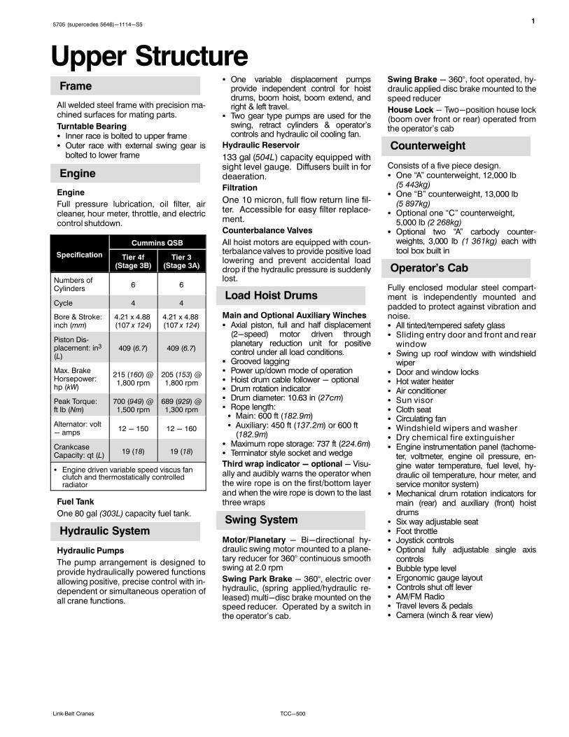
Upper StructureFrame
All welded steel frame with precision machined surfaces for mating parts.
Turntable Bearing� Inner race is bolted to upper frame� Outer race with external swing gear is
bolted to lower frame
Engine
Engine
Full pressure lubrication, oil filter, aircleaner, hour meter, throttle, and electriccontrol shutdown.
Specification
Cummins QSB
Tier 4f(Stage 3B)
Tier 3(Stage 3A)
Numbers ofCylinders
6 6
Cycle 4 4
Bore & Stroke:inch (mm)
4.21 x 4.88 (107 x 124)
4.21 x 4.88 (107 x 124)
Piston Displacement: in3
(L)409 (6.7) 409 (6.7)
Max. BrakeHorsepower:hp (kW)
215 (160) @1,800 rpm
205 (153) @1,800 rpm
Peak Torque:ft lb (Nm)
700 (949) @1,500 rpm
689 (929) @1,300 rpm
Alternator: volt- amps
12 - 150 12 - 160
CrankcaseCapacity: qt (L)
19 (18) 19 (18)
� Engine driven variable speed viscus fanclutch and thermostatically controlledradiator
Fuel Tank
One 80 gal (303L) capacity fuel tank.
Hydraulic System
Hydraulic Pumps
The pump arrangement is designed toprovide hydraulically powered functionsallowing positive, precise control with independent or simultaneous operation ofall crane functions.
� One variable displacement pumpsprovide independent control for hoistdrums, boom hoist, boom extend, andright & left travel.
� Two gear type pumps are used for theswing, retract cylinders & operator'scontrols and hydraulic oil cooling fan.
Hydraulic Reservoir
133 gal (504L) capacity equipped withsight level gauge. Diffusers built in fordeaeration.
Filtration
One 10 micron, full flow return line filter. Accessible for easy filter replacement.
Counterbalance Valves
All hoist motors are equipped with counterbalance valves to provide positive loadlowering and prevent accidental loaddrop if the hydraulic pressure is suddenlylost.
Load Hoist Drums
Main and Optional Auxiliary Winches� Axial piston, full and half displacement
(2-speed) motor driven throughplanetary reduction unit for positivecontrol under all load conditions.
� Grooved lagging� Power up/down mode of operation� Hoist drum cable follower - optional� Drum rotation indicator� Drum diameter: 10.63 in (27cm)� Rope length:� Main: 600 ft (182.9m)� Auxiliary: 450 ft (137.2m) or 600 ft
(182.9m)� Maximum rope storage: 737 ft (224.6m)� Terminator style socket and wedge
Third wrap indicator - optional - Visually and audibly warns the operator whenthe wire rope is on the first/bottom layerand when the wire rope is down to the lastthree wraps
Swing System
Motor/Planetary - Bi-directional hydraulic swing motor mounted to a planetary reducer for 360° continuous smoothswing at 2.0 rpm
Swing Park Brake - 360°, electric overhydraulic, (spring applied/hydraulic released) multi-disc brake mounted on thespeed reducer. Operated by a switch inthe operator's cab.
Swing Brake - 360°, foot operated, hydraulic applied disc brake mounted to thespeed reducer
House Lock - Two-position house lock(boom over front or rear) operated fromthe operator's cab
Counterweight
Consists of a five piece design.� One “A” counterweight, 12,000 lb
(5 443kg)� One “B” counterweight, 13,000 lb
(5 897kg)� Optional one “C” counterweight,
5,000 lb (2 268kg)� Optional two “A” carbody counter
weights, 3,000 lb (1 361kg) each withtool box built in
Operator's Cab
Fully enclosed modular steel compartment is independently mounted andpadded to protect against vibration andnoise.� All tinted/tempered safety glass� Sliding entry door and front and rear
window� Swing up roof window with windshield
wiper� Door and window locks� Hot water heater� Air conditioner� Sun visor� Cloth seat� Circulating fan� Windshield wipers and washer� Dry chemical fire extinguisher� Engine instrumentation panel (tachome
ter, voltmeter, engine oil pressure, engine water temperature, fuel level, hydraulic oil temperature, hour meter, andservice monitor system)
� Mechanical drum rotation indicators formain (rear) and auxiliary (front) hoistdrums
� Six way adjustable seat� Foot throttle� Joystick controls� Optional fully adjustable single axis
controls� Bubble type level� Ergonomic gauge layout� Controls shut off lever� AM/FM Radio� Travel levers & pedals� Camera (winch & rear view)
25705 (supercedes 5646)-1114-S5
TCC-500 Link‐Belt Cranes
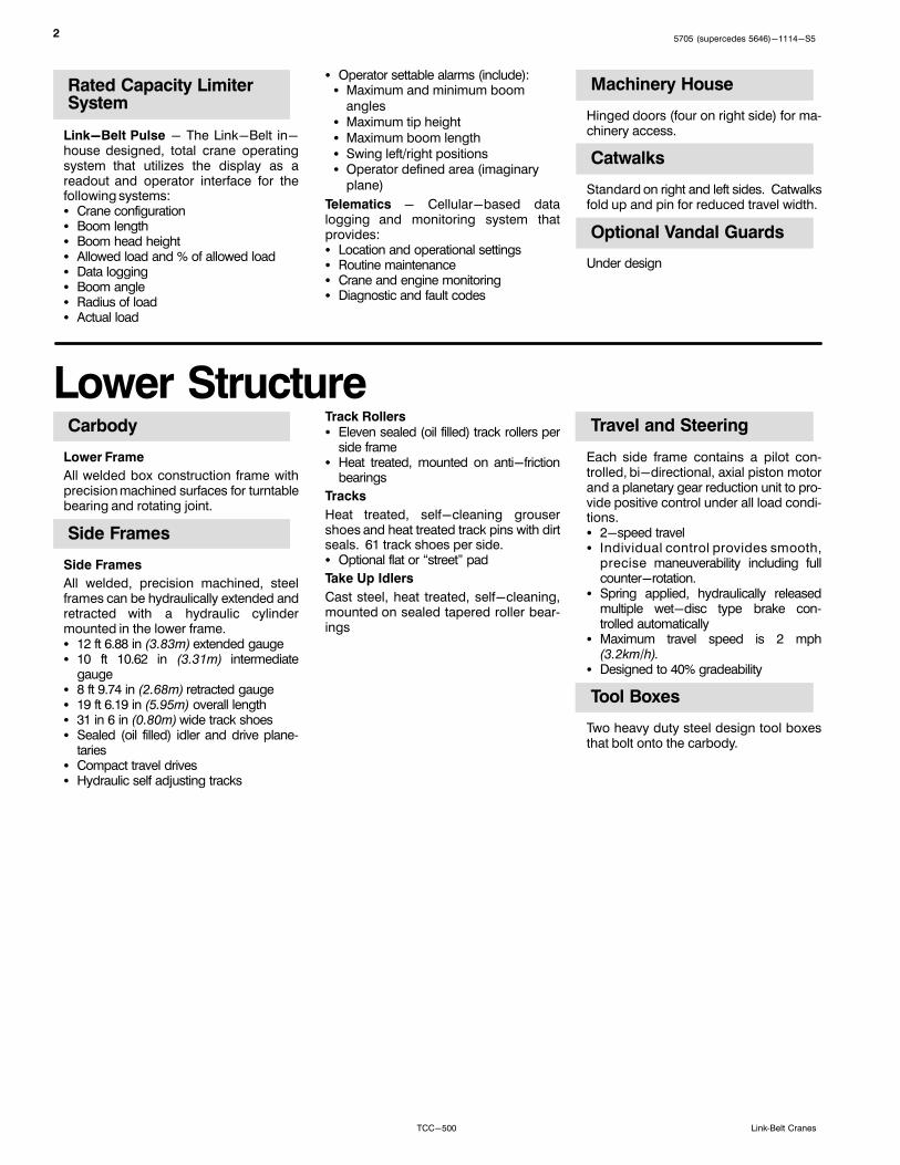
Rated Capacity LimiterSystem
Link-Belt Pulse - The Link-Belt in-house designed, total crane operatingsystem that utilizes the display as areadout and operator interface for thefollowing systems:� Crane configuration� Boom length� Boom head height� Allowed load and % of allowed load� Data logging� Boom angle� Radius of load� Actual load
� Operator settable alarms (include):� Maximum and minimum boom
angles
� Maximum tip height
� Maximum boom length
� Swing left/right positions� Operator defined area (imaginary
plane)
Telematics - Cellular-based datalogging and monitoring system thatprovides:� Location and operational settings� Routine maintenance� Crane and engine monitoring� Diagnostic and fault codes
Machinery House
Hinged doors (four on right side) for machinery access.
Catwalks
Standard on right and left sides. Catwalksfold up and pin for reduced travel width.
Optional Vandal Guards
Under design
Lower StructureCarbody
Lower Frame
All welded box construction frame withprecision machined surfaces for turntablebearing and rotating joint.
Side Frames
Side Frames
All welded, precision machined, steelframes can be hydraulically extended andretracted with a hydraulic cylindermounted in the lower frame.� 12 ft 6.88 in (3.83m) extended gauge� 10 ft 10.62 in (3.31m) intermediate
gauge� 8 ft 9.74 in (2.68m) retracted gauge� 19 ft 6.19 in (5.95m) overall length� 31 in 6 in (0.80m) wide track shoes� Sealed (oil filled) idler and drive plane
taries� Compact travel drives� Hydraulic self adjusting tracks
Track Rollers� Eleven sealed (oil filled) track rollers per
side frame� Heat treated, mounted on anti-friction
bearings
Tracks
Heat treated, self-cleaning grousershoes and heat treated track pins with dirtseals. 61 track shoes per side.� Optional flat or “street” pad
Take Up Idlers
Cast steel, heat treated, self-cleaning,mounted on sealed tapered roller bearings
Travel and Steering
Each side frame contains a pilot controlled, bi-directional, axial piston motorand a planetary gear reduction unit to provide positive control under all load conditions.� 2-speed travel� Individual control provides smooth,
precise maneuverability including fullcounter-rotation.
� Spring applied, hydraulically releasedmultiple wet-disc type brake controlled automatically
� Maximum travel speed is 2 mph(3.2km/h).
� Designed to 40% gradeability
Tool Boxes
Two heavy duty steel design tool boxesthat bolt onto the carbody.
35705 (supercedes 5646)-1114-S5
TCC-500Link‐Belt Cranes
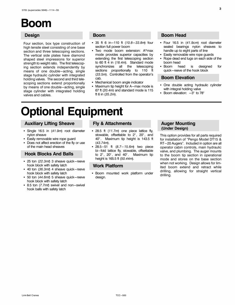
BoomDesign
Four section, box type construction ofhigh tensile steel consisting of one basesection and three telescoping sections.The vertical side plates have diamondshaped steel impressions for superiorstrength to weight ratio. The first telescoping section extends independently bymeans of one double-acting, singlestage hydraulic cylinder with integratedholding valves. The second and third telescoping sections extend proportionallyby means of one double-acting, singlestage cylinder with integrated holdingvalves and cables.
Boom
� 35 ft 6 in-110 ft (10.8-33.8m) foursection full power boom
� Two mode boom extension: A*maxmode provides superior capacities byextending the first telescoping sectionto 60 ft 4 in (18.4m). Standard modesynchronizes all the telescopingsections proportionally to 110 ft(33.5m). Controlled from the operator'scab.
� Mechanical boom angle indicator� Maximum tip height for A-max mode is
67 ft (20.4m) and standard mode is 115ft 6 in (35.2m).
Boom Head
� Four 16.5 in (41.9cm) root diametersealed bearings nylon sheaves tohandle up to eight parts of line
� Easily removable wire rope guards� Rope dead end lugs on each side of the
boom head� Boom head is designed for
quick-reeve of the hook block
Boom Elevation
� One double acting hydraulic cylinderwith integral holding valve
� Boom elevation: -3° to 78°
Optional EquipmentAuxiliary Lifting Sheave
� Single 16.5 in (41.9m) root diameternylon sheave
� Easily removable wire rope guard� Does not affect erection of the fly or use
of the main head sheaves
Hook Blocks And Balls
� 25 ton (22.3mt) 3 sheave quick-reevehook block with safety latch
� 40 ton (36.3mt) 4 sheave quick-reevehook block with safety latch
� 50 ton (44.6mt) 5 sheave quick-reevehook block with safety latch
� 8.5 ton (7.7mt) swivel and non-swivelhook balls with safety latch
Fly & Attachments
� 28.5 ft (11.7m) one piece lattice fly,stowable, offsettable to 2° , 20° , and40° . Maximum tip height is 143.5 ft(43.74m).
� 28.5-51 ft (8.7-15.6m) two piecebi-fold lattice fly, stowable, offsettableto 2° , 20° , and 40° . Maximum tipheight is 165.5 ft (50.44m).
Work Platform
� Boom mounted work platform underdesign.
Auger Mounting(Under Design)
This option provides for all parts requiredfor installation of “Pengo Model DT15 &RT-20 Augers”. Included in option are alloperator cabin controls, main hydraulicvalve, and plumbing. The auger mountsto the boom tip section in operationalmode and stores on the base sectionwhen not working. Design allows for limited boom extend and retract whiledrilling, allowing for straight verticaldrilling.
45705 (supercedes 5646)-1114-S5
TCC-500 Link‐Belt Cranes
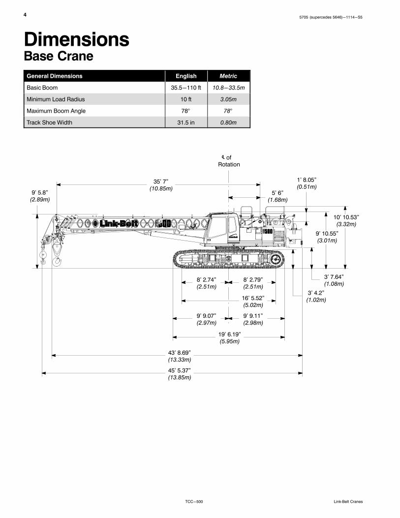
DimensionsBase Crane
General Dimensions English Metric
Basic Boom 35.5-110 ft 10.8-33.5m
Minimum Load Radius 10 ft 3.05m
Maximum Boom Angle 78° 78°
Track Shoe Width 31.5 in 0.80m
8' 2.74”(2.51m)
35' 7”(10.85m)
3' 4.2”(1.02m)
1' 8.05”(0.51m)
9' 10.55”(3.01m)
10' 10.53”(3.32m)
9' 5.8”(2.89m)
5' 6”(1.68m)
ofRotation
3' 7.64”(1.08m)
8' 2.79”(2.51m)
16' 5.52”(5.02m)
9' 9.07”(2.97m)
9' 9.11”(2.98m)
19' 6.19”(5.95m)
43' 8.69”(13.33m)
45' 5.37”(13.85m)
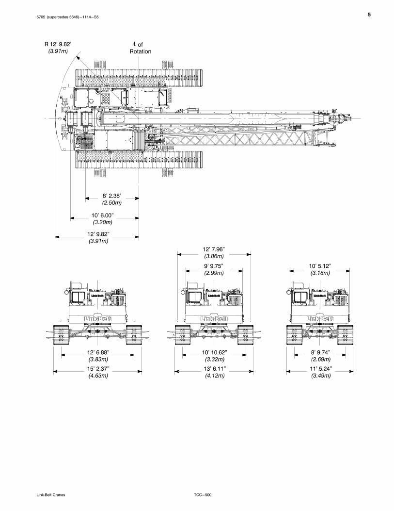
55705 (supercedes 5646)-1114-S5
TCC-500Link‐Belt Cranes
12' 9.82”(3.91m)
12' 6.88”(3.83m)
10' 6.00”(3.20m)
8' 2.38'(2.50m)
R 12' 9.82'(3.91m)
ofRotation
15' 2.37”(4.63m)
10' 10.62”(3.32m)
13' 6.11”(4.12m)
8' 9.74”(2.69m)
11' 5.24”(3.49m)
9' 9.75”(2.99m)
12' 7.96”(3.86m)
10' 5.12”(3.18m)

65705 (supercedes 5646)-1114-S5
TCC-500 Link‐Belt Cranes
W
Number inside black circle “�” = # of components
* - Optional equipment
Auxiliary Lifting SheaveAuxiliary Lifting Sheave �
Length 35.31 in (0.90m)
Width 16.31 in (0.41m)
Height 19 in (0.48m)
Weight 92.5 lb (42kg)
L
W
H
Fly28.5 ft (8.69m) Offset Fly One Piece
Lattice Fly (Base Fly) �
Length 28.5 ft (8.69m)
Width 29 in (0.74m)
Height 30 in (0.76m)
Weight 1,188 lb (539kg)
22.5 ft (6.86m) Lattice Fly Tip(Addition To Base Fly For28.5-51 ft (8.69-15.55m)
Bi-fold Fly) �
Length 22.5 ft (6.86m)
Width 13.78 in (0.35m)
Height 20 in (0.51m)
Weight 654 lb (297kg)
L
H
L
W
H
75705 (supercedes 5646)-1114-S5
TCC-500Link‐Belt Cranes
Number inside black circle “�” = # of components
* - Optional equipment
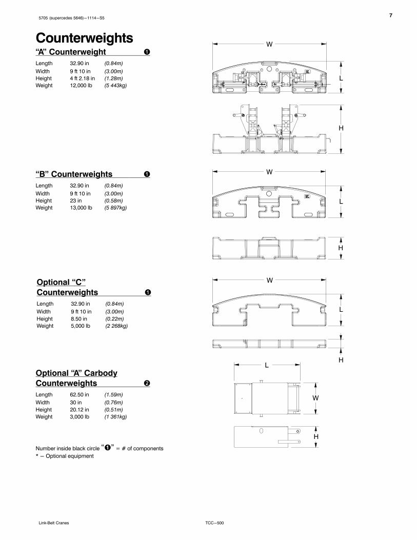
Counterweights“A” Counterweight �
Length 32.90 in (0.84m)
Width 9 ft 10 in (3.00m)
Height 4 ft 2.18 in (1.28m)
Weight 12,000 lb (5 443kg)
“B” Counterweights �
Length 32.90 in (0.84m)
Width 9 ft 10 in (3.00m)
Height 23 in (0.58m)
Weight 13,000 lb (5 897kg)
Optional “A” Carbody
Counterweights �
Length 62.50 in (1.59m)
Width 30 in (0.76m)
Height 20.12 in (0.51m)
Weight 3,000 lb (1 361kg)
W
H
L
H
L
W
H
L
W
Optional “C”
Counterweights �
Length 32.90 in (0.84m)
Width 9 ft 10 in (3.00m)
Height 8.50 in (0.22m)
Weight 5,000 lb (2 268kg)
W
H
L
85705 (supercedes 5646)-1114-S5
TCC-500 Link‐Belt Cranes
W1
Number inside black circle “�” = # of components
* - Optional equipment
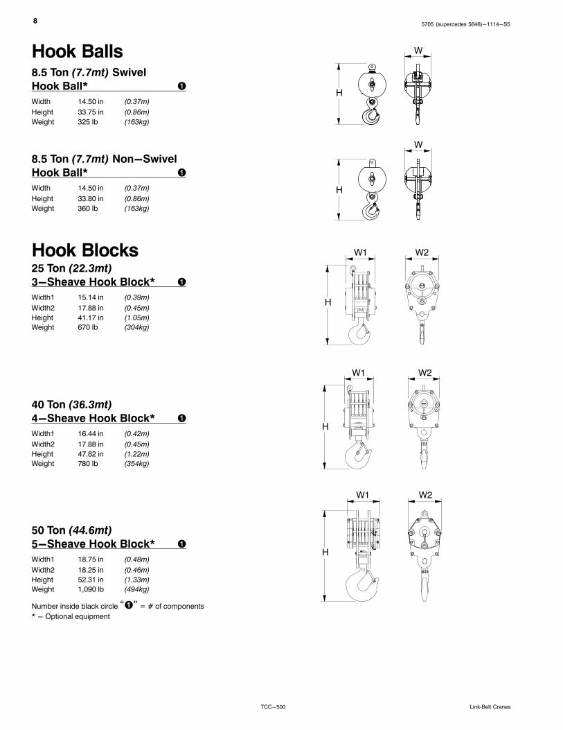
8.5 Ton (7.7mt) Non-Swivel
Hook Ball* �
Width 14.50 in (0.37m)
Height 33.80 in (0.86m)
Weight 360 lb (163kg)
Hook Balls8.5 Ton (7.7mt) Swivel
Hook Ball* �
Width 14.50 in (0.37m)
Height 33.75 in (0.86m)
Weight 325 lb (163kg)
H
W
H
W
Hook Blocks
50 Ton (44.6mt)
5-Sheave Hook Block* �
Width1 18.75 in (0.48m)
Width2 18.25 in (0.46m)
Height 52.31 in (1.33m)
Weight 1,090 lb (494kg)
25 Ton (22.3mt)
3-Sheave Hook Block* �
Width1 15.14 in (0.39m)
Width2 17.88 in (0.45m)
Height 41.17 in (1.05m)
Weight 670 lb (304kg)
40 Ton (36.3mt)
4-Sheave Hook Block* �
Width1 16.44 in (0.42m)
Width2 17.88 in (0.45m)
Height 47.82 in (1.22m)
Weight 780 lb (354kg)
H
W2
W1
H
W2
W1
H
W2
95705 (supercedes 5646)-1114-S5
TCC-500Link‐Belt Cranes
Number inside black circle “�” = # of components
* - Optional equipment
AugersDT-15 Auger* �
Width 16.12 in (0.41m)
Height 52.12 in (1.32m)
Weight 710 lb (322kg)
Hex Shaft 2.5 in (6.35cm)H
RT-20 Auger* �
Width 16.12 in (0.41m)
Height 52.12 in (1.32m)
Weight 737 lb (334kg)
Hex Shaft 3 in (7.62cm)
W
H
W
105705 (supercedes 5646)-1114-S5
TCC-500 Link‐Belt Cranes
Working WeightsOption Description
Gross Weightlb (kg)
GroundBearingPressure(on softground)
psi (kg/cm2)
1Base crane, “AB” counterweight, lower toolbox, 600 ft (182.9m) type “ZB” main wire rope, 450 ft (137.2m) type “ZB”auxiliary wire rope, 2-piece fly, 40 ton (36.29mt) 4 sheave hook block, 8.5 ton (7.71mt) hook ball, and a 250 lb(113kg) operator.
100,000(45 359kg)
8.88(0.62)
Notes: Ground bearing pressure is based on the total weight distributed evenly over the track contact area.
GCTransport Drawing
Transport Weight - 99,750 lb (45 246kg)Base crane, “AB” Counterweight, 600 ft (182.9m) type “ZB” main wire rope, 450 ft (137.2m)
type “ZB” auxiliary wire rope, 2-piece fly, 40 ton (36.29mt) 4 sheave hook block, and 8.5 ton
2' 0.05”(0.61m)
LC 1' 8”(0.51m)
Load Hoist PerformanceMain (Rear) and Auxiliary (Front) Winches - 5/8 in (16mm) Rope
Maximum Line Pull Normal Line Speed High Line Speed Layer Total
Layer lb kN ft/min m/min ft/min m/min ft m ft m
1 17,084 75.99 181 55.2 360 109.6 97 29.6 97 29.6
2 15,454 68.74 200 61.1 398 121.2 107 32.6 205 62.4
3 14,107 62.75 219 66.9 436 132.8 118 35.9 322 98.3
4 12,977 57,72 239 72.7 474 144.3 128 39.0 451 137.3
5 12,014 53.44 258 78.6 511 155.9 138 42.1 589 179.5
6 11,184 49.75 277 84.4 549 167.5 149 45.3 737 224.7
Wire Rope ApplicationDiameter
Type
MaximumPermissible
Load
in mm lb kg
Main (Rear) Winch
Standard 5/8 16 34x7 rotation resistant - right regular lay or right lang lay (Type ZB) 11,080 5 025.8
Optional 5/8 16 18x19 rotation resistant - right regular lay or right lang lay (Type RB) 9,080 4 118.6
Optional 5/8 16 6x19 IWRC - right regular lay (Type DB) 11,771 5 339.2
Auxiliary (Front)Winch
Standard 5/8 16 34x7 rotation resistant - right regular lay (Type ZB) 11,080 5 025.8
Optional 5/8 16 18x19 rotation resistant - right regular lay (Type RB) 9,080 4 118.6
Optional 5/8 16 6x19 IWRC - right regular lay (Type DB) 11,771 5 339.2

115705 (supercedes 5646)-1114-S5
TCC-500Link‐Belt Cranes
Working Areas
Boom
Blo
cked
Ove
r Fro
nt
Center Of Rotation
Of CrawlerLongitudinal
SeeNoteIdler Sprocket
Note: These Lines Determine The Limiting Position Of Any Load For Operation Within Working Areas Indicated.
Drive Sprocket
See Note
360°
125705 (supercedes 5646)-1114-S5
TCC-500 Link‐Belt Cranes
Boom Extend ModesBoom Mode “A” (A−max)
Boom Mode “B” (Standard)
Only inner mid section telescopes.
Inner mid, outer mid, and tip sectionstelescope simultaneously.
Base SectionTip Section288” (7.57m) Stroke
BoomLength
35.5' (10.82m)
40' (12.2m)
50' (15.2m)
60.3' (18.38m)
50' (15.2m)
60' (18.3m)
70' (21.3m)
80' (24.4m)
90' (27.4m)
100' (30.5m)
110' (33.5m)
Outer Mid Section288” (7.57m) Stroke
Inner Mid Section288” (7.57m) Stroke
Base SectionInner Mid Section288” (7.57m) Stroke
BoomLength
35.5' (10.82m)
40' (12.2m)
35.5-110 ft (10.82-33.53m)Main Boom
35.5-110 ft (10.82-33.53m) Main BoomWith 28.5-51 ft (8.69-15.54m) Offset Fly
OffsetFly
MainBoom
MainBoom
135705 (supercedes 5646)-1114-S5
TCC-500Link‐Belt Cranes
Attachments
145705 (supercedes 5646)-1114-S5
TCC-500 Link‐Belt Cranes
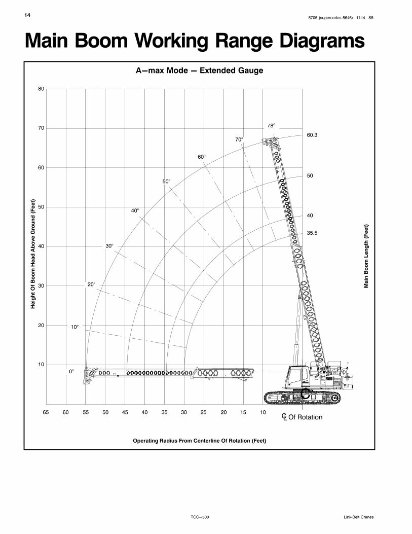
Main Boom Working Range Diagrams
C
ÏÏÏÏÏÏÏÏÏÏÏÏÏÏÏÏÏÏÏ
ÏÏÏÏÏÏÏÏÏÏÏÏÏÏÏÏÏÏÏÏÏÏ ÏÏÏÏÏÏÏÏÏÏÏÏÏ
ÏÏÏÏÏÏÏÏÏ ÏÏÏÏÏÏÏÏÏÏÏÏÏÏÏÏÏÏ
ÏÏÏÏÏÏÏÏÏÏÏÏÏÏÏÏÏÏÏÏÏÏÏÏÏÏÏÏÏÏÏÏÏÏÏÏ
A-max Mode - Extended Gauge
Main
Bo
om
Len
gth
(Feet)
Heig
ht
Of
Bo
om
Head
Ab
ove G
rou
nd
(Feet)
Operating Radius From Centerline Of Rotation (Feet)
60.3
CL Of Rotation
50
40
35.5
10
20
30
40
50
60
70
80
101520253035404550556065
ÁÁ10°
ÁÁÁÁ
78°
ÁÁ70°
ÁÁÁÁÁÁ
60°
ÁÁ50°
ÁÁ40°
ÁÁÁÁÁÁ
30°
ÁÁ20°
ÁÁÁÁ
0°
155705 (supercedes 5646)-1114-S5
TCC-500Link‐Belt Cranes
Ï
ÏÏÏÏÏÏ Ï Ï Ï Ï
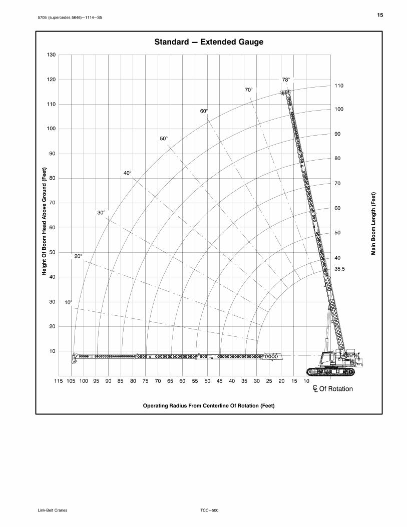
Standard - Extended Gauge
Main
Bo
om
Len
gth
(Feet)
Heig
ht
Of
Bo
om
Head
Ab
ove G
rou
nd
(Feet)
Operating Radius From Centerline Of Rotation (Feet)
110
CL Of Rotation
90
40
35.5
10
20
30
40
50
60
70
80
101520253035404550556065
ÁÁ10°
ÁÁÁÁ
78°
ÁÁÁÁÁÁ
70°
ÁÁÁÁ
60°
ÁÁ50°
ÁÁÁÁÁÁ
40°
ÁÁÁÁ
30°
ÁÁÁÁÁÁ
20°
90
100
110
120
130
707580859095100105115
100
80
70
60
50
165705 (supercedes 5646)-1114-S5
TCC-500 Link‐Belt Cranes
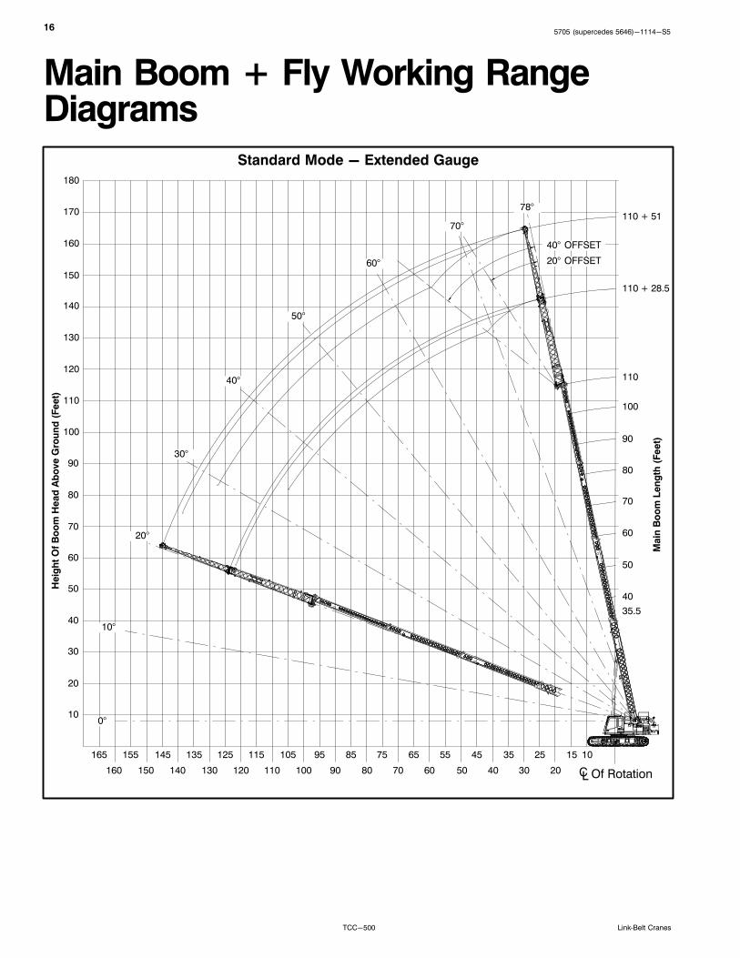
Main Boom + Fly Working RangeDiagrams
20
ÏÏ
Ï
Ï
ÏÏ
Ï
Ï
Ï
ÏÏ
Ï
Standard Mode - Extended Gauge
Main
Bo
om
Len
gth
(Feet)
Heig
ht
Of
Bo
om
Head
Ab
ove G
rou
nd
(Feet)
110
CL Of Rotation
90
40
35.5
10
20
30
40
50
60
70
80
101525
30
35
40
45
50
55
60
65
ÁÁÁÁ
10°
ÁÁÁÁÁÁ
78°
ÁÁÁÁÁÁ
70°
ÁÁÁÁ
60°
ÁÁÁÁ
50°
ÁÁÁ40°
ÁÁ30°
ÁÁÁÁÁÁ
20°
90
100
110
120
130
70
75
80
85
90
95
100
105115
100
80
70
60
50
110 + 28.5
110 + 51
ÁÁÁÁÁÁ
0°
125135145155165
110120130140150160
140
150
160
170
180
ÁÁÁÁÁÁÁÁ
40° OFFSET
ÁÁÁÁÁÁÁÁ
20° OFFSET
175705 (supercedes 5646)-1114-S5
TCC-500Link‐Belt Cranes
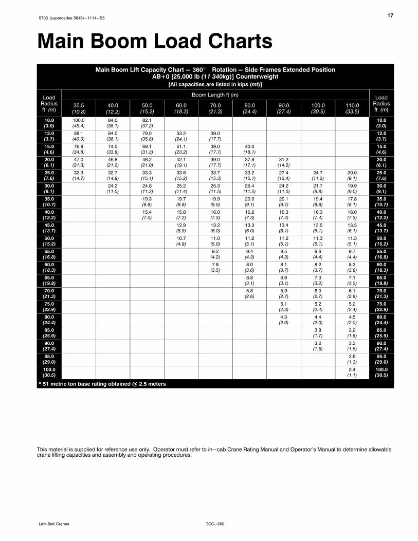
Main Boom Load ChartsMain Boom Lift Capacity Chart - 360� Rotation - Side Frames Extended Position
AB+0 [25,000 lb (11 340kg)] Counterweight
[All capacities are listed in kips (mt)]
LoadRadiusft (m)
Boom Length ft (m)Load
Radiusft (m)
35.5(10.8)
40.0(12.2)
50.0(15.2)
60.0(18.3)
70.0(21.3)
80.0(24.4)
90.0(27.4)
100.0(30.5)
110.0(33.5)
10.0(3.0)
100.0(45.4)
84.0(38.1)
82.1(37.2)
10.0(3.0)
12.0(3.7)
88.1(40.0)
84.0(38.1)
79.0(35.8)
53.2(24.1)
39.0(17.7)
12.0(3.7)
15.0(4.6)
76.8(34.8)
74.5(33.8)
69.1(31.3)
51.1(23.2)
39.0(17.7)
40.0(18.1)
15.0(4.6)
20.0(6.1)
47.0(21.3)
46.8(21.2)
46.2(21.0)
42.1(19.1)
39.0(17.7)
37.8(17.1)
31.2(14.2)
20.0(6.1)
25.0(7.6)
32.3(14.7)
32.7(14.8)
33.3(15.1)
33.6(15.2)
33.7(15.3)
33.2(15.1)
27.4(12.4)
24.7(11.2)
20.0(9.1)
25.0(7.6)
30.0(9.1)
24.2(11.0)
24.8(11.2)
25.2(11.4)
25.3(11.5)
25.4(11.5)
24.2(11.0)
21.7(9.8)
19.9(9.0)
30.0(9.1)
35.0(10.7)
19.3(8.8)
19.7(8.9)
19.9(9.0)
20.0(9.1)
20.1(9.1)
19.4(8.8)
17.8(8.1)
35.0(10.7)
40.0(12.2)
15.4(7.0)
15.8(7.2)
16.0(7.3)
16.2(7.3)
16.3(7.4)
16.3(7.4)
16.0(7.3)
40.0(12.2)
45.0(13.7)
12.9(5.9)
13.2(6.0)
13.3(6.0)
13.4(6.1)
13.5(6.1)
13.5(6.1)
45.0(13.7)
50.0(15.2)
10.7(4.9)
11.0(5.0)
11.2(5.1)
11.2(5.1)
11.3(5.1)
11.3(5.1)
50.0(15.2)
55.0(16.8)
9.2(4.2)
9.4(4.3)
9.5(4.3)
9.6(4.4)
9.7(4.4)
55.0(16.8)
60.0(18.3)
7.8(3.5)
8.0(3.6)
8.1(3.7)
8.2(3.7)
8.3(3.8)
60.0(18.3)
65.0(19.8)
6.8(3.1)
6.9(3.1)
7.0(3.2)
7.1(3.2)
65.0(19.8)
70.0(21.3)
5.8(2.6)
5.9(2.7)
6.0(2.7)
6.1(2.8)
70.0(21.3)
75.0(22.9)
5.1(2.3)
5.2(2.4)
5.2(2.4)
75.0(22.9)
80.0(24.4)
4.3(2.0)
4.4(2.0)
4.5(2.0)
80.0(24.4)
85.0(25.9)
3.8(1.7)
3.9(1.8)
85.0(25.9)
90.0(27.4)
3.2(1.5)
3.3(1.5)
90.0(27.4)
95.0(29.0)
2.8(1.3)
95.0(29.0)
100.0(30.5)
2.4(1.1)
100.0(30.5)
* 51 metric ton base rating obtained @ 2.5 meters
This material is supplied for reference use only. Operator must refer to in-cab Crane Rating Manual and Operator's Manual to determine allowablecrane lifting capacities and assembly and operating procedures.
185705 (supercedes 5646)-1114-S5
TCC-500 Link‐Belt Cranes
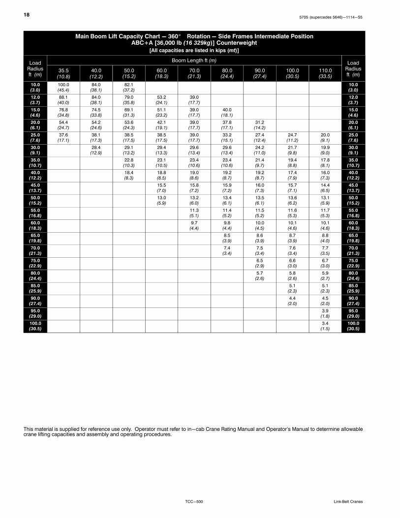
Main Boom Lift Capacity Chart - 360� Rotation - Side Frames Intermediate PositionABC+A [36,000 lb (16 329kg)] Counterweight
[All capacities are listed in kips (mt)]
LoadRadiusft (m)
Boom Length ft (m)Load
Radiusft (m)
35.5(10.8)
40.0(12.2)
50.0(15.2)
60.0(18.3)
70.0(21.3)
80.0(24.4)
90.0(27.4)
100.0(30.5)
110.0(33.5)
10.0(3.0)
100.0(45.4)
84.0(38.1)
82.1(37.2)
10.0(3.0)
12.0(3.7)
88.1(40.0)
84.0(38.1)
79.0(35.8)
53.2(24.1)
39.0(17.7)
12.0(3.7)
15.0(4.6)
76.8(34.8)
74.5(33.8)
69.1(31.3)
51.1(23.2)
39.0(17.7)
40.0(18.1)
15.0(4.6)
20.0(6.1)
54.4(24.7)
54.2(24.6)
53.6(24.3)
42.1(19.1)
39.0(17.7)
37.8(17.1)
31.2(14.2)
20.0(6.1)
25.0(7.6)
37.6(17.1)
38.1(17.3)
38.5(17.5)
38.5(17.5)
39.0(17.7)
33.2(15.1)
27.4(12.4)
24.7(11.2)
20.0(9.1)
25.0(7.6)
30.0(9.1)
28.4(12.9)
29.1(13.2)
29.4(13.3)
29.6(13.4)
29.6(13.4)
24.2(11.0)
21.7(9.8)
19.9(9.0)
30.0(9.1)
35.0(10.7)
22.8(10.3)
23.1(10.5)
23.4(10.6)
23.4(10.6)
21.4(9.7)
19.4(8.8)
17.8(8.1)
35.0(10.7)
40.0(12.2)
18.4(8.3)
18.8(8.5)
19.0(8.6)
19.2(8.7)
19.2(8.7)
17.4(7.9)
16.0(7.3)
40.0(12.2)
45.0(13.7)
15.5(7.0)
15.8(7.2)
15.9(7.2)
16.0(7.3)
15.7(7.1)
14.4(6.5)
45.0(13.7)
50.0(15.2)
13.0(5.9)
13.2(6.0)
13.4(6.1)
13.5(6.1)
13.6(6.2)
13.1(5.9)
50.0(15.2)
55.0(16.8)
11.3(5.1)
11.4(5.2)
11.5(5.2)
11.6(5.3)
11.7(5.3)
55.0(16.8)
60.0(18.3)
9.7(4.4)
9.8(4.4)
10.0(4.5)
10.1(4.6)
10.1(4.6)
60.0(18.3)
65.0(19.8)
8.5(3.9)
8.6(3.9)
8.7(3.9)
8.8(4.0)
65.0(19.8)
70.0(21.3)
7.4(3.4)
7.5(3.4)
7.6(3.4)
7.7(3.5)
70.0(21.3)
75.0(22.9)
6.5(2.9)
6.6(3.0)
6.7(3.0)
75.0(22.9)
80.0(24.4)
5.7(2.6)
5.8(2.6)
5.9(2.7)
80.0(24.4)
85.0(25.9)
5.1(2.3)
5.1(2.3)
85.0(25.9)
90.0(27.4)
4.4(2.0)
4.5(2.0)
90.0(27.4)
95.0(29.0)
3.9(1.8)
95.0(29.0)
100.0(30.5)
3.4(1.5)
100.0(30.5)
This material is supplied for reference use only. Operator must refer to in-cab Crane Rating Manual and Operator's Manual to determine allowablecrane lifting capacities and assembly and operating procedures.

195705 (supercedes 5646)-1114-S5
TCC-500Link‐Belt Cranes
Main Boom + Fly Load Charts90 ft (27.4m) Main Boom + Fly - 360� Rotation - Standard Mode - Side Frames Extended Position
AB+0 [25,000 lb (11 340kg)] Counterweight
[All capacities are listed in kips (mt)]
LoadRadiusft (m)
28.25 ft Manual Offset Fly 51 ft Manual Offset Fly LoadRadiusft (m)2° 20° 40° 2° 20° 40°
30(9.1)
16.7(7.6)
30(9.1)
35(10.7)
15.5(7.0)
9.7(4.4)
35(10.7)
40(12.2)
14.5(6.6)
10.5(4.8)
8.6(3.9)
40(12.2)
45(13.7)
13.5(6.1)
9.9(4.5)
7.9(3.6)
8.1(3.7)
45(13.7)
50(15.2)
12.0(5.4)
9.4(4.3)
7.6(3.4)
7.5(3.4)
5.4(2.4)
50(15.2)
55(16.8)
10.4(4.7)
8.9(4.0)
7.4(3.4)
7.0(3.2)
5.1(2.3)
55(16.8)
60(18.3)
8.9(4.0)
8.7(3.9)
7.2(3.3)
6.5(2.9)
4.9(2.2)
60(18.3)
65(19.8)
7.7(3.5)
8.2(3.7)
7.0(3.2)
6.1(2.8)
4.6(2.1)
3.7(1.7)
65(19.8)
70(21.3)
6.7(3.0)
7.2(3.3)
6.8(3.1)
5.7(2.6)
4.4(2.0)
3.5(1.6)
70(21.3)
75(22.9)
5.9(2.7)
6.2(2.8)
6.5(2.9)
5.4(2.4)
4.2(1.9)
3.4(1.5)
75(22.9)
80(24.4)
5.1(2.3)
5.5(2.5)
5.7(2.6)
5.1(2.3)
4.0(1.8)
3.3(1.5)
80(24.4)
85(25.9)
4.5(2.0)
4.8(2.2)
4.9(2.2)
4.8(2.2)
3.9(1.8)
3.3(1.5)
85(25.9)
90(27.4)
3.9(1.8)
4.1(1.9)
4.3(2.0)
4.4(2.0)
3.7(1.7)
3.2(1.5)
90(27.4)
95(29.0)
3.4(1.5)
3.6(1.6)
3.7(1.7)
3.9(1.8)
3.6(1.6)
3.1(1.4)
95(29.0)
100(30.5)
2.9(1.3)
3.1(1.4)
3.4(1.5)
3.5(1.6)
3.1(1.4)
100(30.5)
105(32.0)
2.5(1.1)
2.6(1.2)
3.0(1.4)
3.4(1.5)
3.1(1.4)
105(32.0)
110(33.5)
2.2(1.0)
2.7(1.2)
3.0(1.4)
3.0(1.4)
110(33.5)
115(35.1)
2.3(1.0)
2.6(1.2)
2.7(1.2)
115(35.1)
120(36.6)
2.0(0.9)
2.2(1.0)
120(36.6)
125(38.1)
1.8(0.8)
1.9(0.9)
125(38.1)
130(39.6)
1.5(0.7)
1.6(0.7)
130(39.6)
135(41.1)
1.3(0.6)
135(41.1)
This material is supplied for reference use only. Operator must refer to in-cab Crane Rating Manual and Operator's Manual to determine allowablecrane lifting capacities and assembly and operating procedures.
205705 (supercedes 5646)-1114-S5
TCC-500 Link‐Belt Cranes
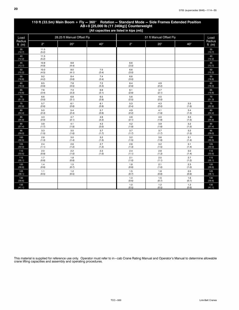
110 ft (33.5m) Main Boom + Fly - 360� Rotation - Standard Mode - Side Frames Extended PositionAB+0 [25,000 lb (11 340kg)] Counterweight
[All capacities are listed in kips (mt)]
LoadRadiusft (m)
28.25 ft Manual Offset Fly 51 ft Manual Offset Fly LoadRadiusft (m)2° 20° 40° 2° 20° 40°
35(10.7)
11.5(5.2)
35(10.7)
40(12.2)
11.5(5.2)
40(12.2)
45(13.7)
10.9(4.9)
9.8(4.4)
6.6(3.0)
45(13.7)
50(15.2)
10.0(4.5)
9.0(4.1)
7.5(3.4)
6.6(3.0)
50(15.2)
55(16.8)
9.2(4.2)
8.4(3.8)
7.4(3.4)
6.6(3.0)
55(16.8)
60(18.3)
8.5(3.9)
7.8(3.5)
7.2(3.3)
6.4(2.9)
4.9(2.2)
60(18.3)
65(19.8)
7.6(3.4)
7.3(3.3)
6.9(3.1)
6.1(2.8)
4.7(2.1)
65(19.8)
70(21.3)
6.6(3.0)
6.8(3.1)
6.5(2.9)
5.6(2.5)
4.5(2.0)
70(21.3)
75(22.9)
5.7(2.6)
6.1(2.8)
6.1(2.8)
5.3(2.4)
4.3(2.0)
3.5(1.6)
75(22.9)
80(24.4)
5.0(2.3)
5.4(2.4)
5.7(2.6)
4.9(2.2)
4.1(1.9)
3.4(1.5)
80(24.4)
85(25.9)
4.3(2.0)
4.7(2.1)
4.9(2.2)
4.6(2.1)
4.0(1.8)
3.3(1.5)
85(25.9)
90(27.4)
3.8(1.7)
4.1(1.9)
4.3(2.0)
4.2(1.9)
3.9(1.8)
3.2(1.5)
90(27.4)
95(29.0)
3.3(1.5)
3.5(1.6)
3.7(1.7)
3.7(1.7)
3.7(1.7)
3.2(1.5)
95(29.0)
100(30.5)
2.8(1.3)
3.0(1.4)
3.2(1.5)
3.2(1.5)
3.6(1.6)
3.1(1.4)
100(30.5)
105(32.0)
2.4(1.1)
2.6(1.2)
2.7(1.2)
2.8(1.3)
3.2(1.5)
3.1(1.4)
105(32.0)
110(33.5)
2.0(0.9)
2.2(1.0)
2.3(1.0)
2.4(1.1)
2.8(1.3)
3.0(1.4)
110(33.5)
115(35.1)
1.7(0.8)
1.8(0.8)
2.1(1.0)
2.5(1.1)
2.7(1.2)
115(35.1)
120(36.6)
1.4(0.6)
1.5(0.7)
1.8(0.8)
2.1(1.0)
2.3(1.0)
120(36.6)
125(38.1)
1.1(0.5)
1.2(0.5)
1.5(0.7)
1.8(0.8)
2.0(0.9)
125(38.1)
130(39.6)
1.3(0.6)
1.5(0.7)
1.6(0.7)
130(39.6)
135(41.1)
1.0(0.5)
1.2(0.5)
1.3(0.6)
135(41.1)
This material is supplied for reference use only. Operator must refer to in-cab Crane Rating Manual and Operator's Manual to determine allowablecrane lifting capacities and assembly and operating procedures.
215705 (supercedes 5646)-1114-S5
TCC-500Link‐Belt Cranes
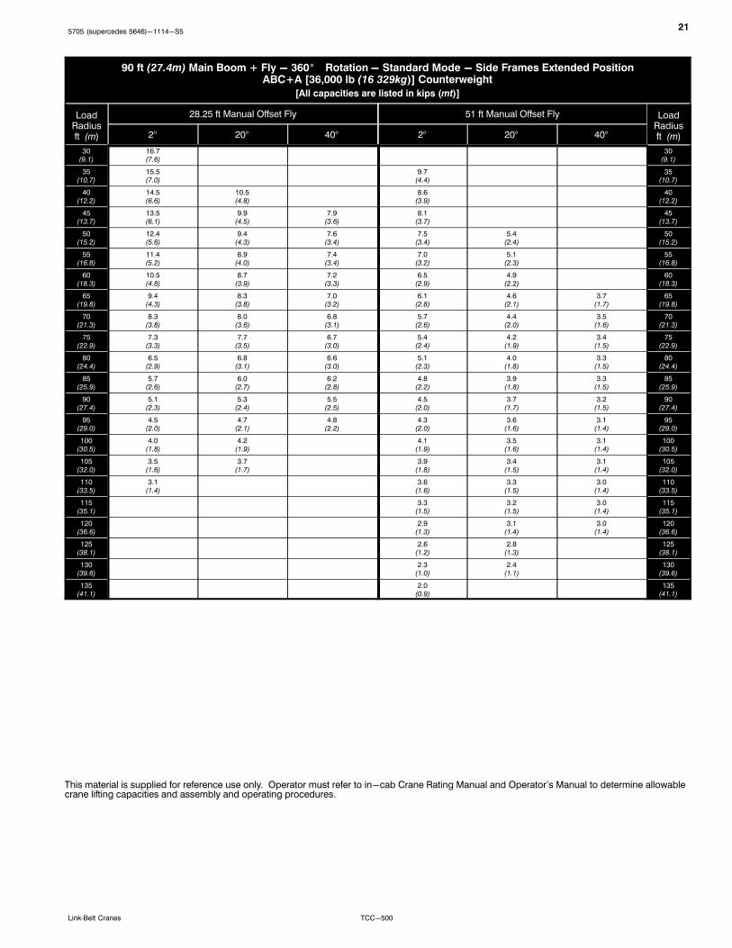
90 ft (27.4m) Main Boom + Fly - 360� Rotation - Standard Mode - Side Frames Extended PositionABC+A [36,000 lb (16 329kg)] Counterweight
[All capacities are listed in kips (mt)]
LoadRadiusft (m)
28.25 ft Manual Offset Fly 51 ft Manual Offset Fly LoadRadiusft (m)2° 20° 40° 2° 20° 40°
30(9.1)
16.7(7.6)
30(9.1)
35(10.7)
15.5(7.0)
9.7(4.4)
35(10.7)
40(12.2)
14.5(6.6)
10.5(4.8)
8.6(3.9)
40(12.2)
45(13.7)
13.5(6.1)
9.9(4.5)
7.9(3.6)
8.1(3.7)
45(13.7)
50(15.2)
12.4(5.6)
9.4(4.3)
7.6(3.4)
7.5(3.4)
5.4(2.4)
50(15.2)
55(16.8)
11.4(5.2)
8.9(4.0)
7.4(3.4)
7.0(3.2)
5.1(2.3)
55(16.8)
60(18.3)
10.5(4.8)
8.7(3.9)
7.2(3.3)
6.5(2.9)
4.9(2.2)
60(18.3)
65(19.8)
9.4(4.3)
8.3(3.8)
7.0(3.2)
6.1(2.8)
4.6(2.1)
3.7(1.7)
65(19.8)
70(21.3)
8.3(3.8)
8.0(3.6)
6.8(3.1)
5.7(2.6)
4.4(2.0)
3.5(1.6)
70(21.3)
75(22.9)
7.3(3.3)
7.7(3.5)
6.7(3.0)
5.4(2.4)
4.2(1.9)
3.4(1.5)
75(22.9)
80(24.4)
6.5(2.9)
6.8(3.1)
6.6(3.0)
5.1(2.3)
4.0(1.8)
3.3(1.5)
80(24.4)
85(25.9)
5.7(2.6)
6.0(2.7)
6.2(2.8)
4.8(2.2)
3.9(1.8)
3.3(1.5)
85(25.9)
90(27.4)
5.1(2.3)
5.3(2.4)
5.5(2.5)
4.5(2.0)
3.7(1.7)
3.2(1.5)
90(27.4)
95(29.0)
4.5(2.0)
4.7(2.1)
4.8(2.2)
4.3(2.0)
3.6(1.6)
3.1(1.4)
95(29.0)
100(30.5)
4.0(1.8)
4.2(1.9)
4.1(1.9)
3.5(1.6)
3.1(1.4)
100(30.5)
105(32.0)
3.5(1.6)
3.7(1.7)
3.9(1.8)
3.4(1.5)
3.1(1.4)
105(32.0)
110(33.5)
3.1(1.4)
3.6(1.6)
3.3(1.5)
3.0(1.4)
110(33.5)
115(35.1)
3.3(1.5)
3.2(1.5)
3.0(1.4)
115(35.1)
120(36.6)
2.9(1.3)
3.1(1.4)
3.0(1.4)
120(36.6)
125(38.1)
2.6(1.2)
2.8(1.3)
125(38.1)
130(39.6)
2.3(1.0)
2.4(1.1)
130(39.6)
135(41.1)
2.0(0.9)
135(41.1)
This material is supplied for reference use only. Operator must refer to in-cab Crane Rating Manual and Operator's Manual to determine allowablecrane lifting capacities and assembly and operating procedures.
225705 (supercedes 5646)-1114-S5
TCC-500 Link‐Belt Cranes
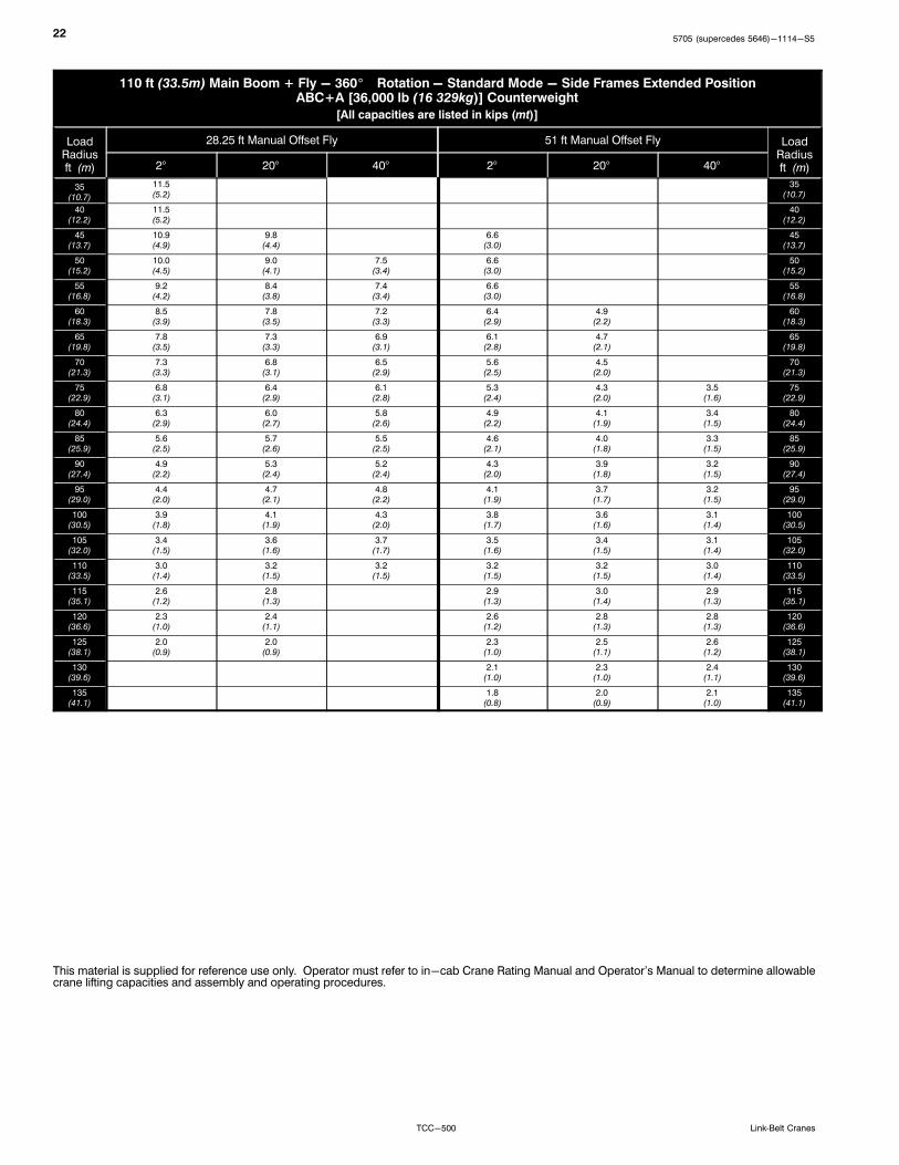
110 ft (33.5m) Main Boom + Fly - 360� Rotation - Standard Mode - Side Frames Extended PositionABC+A [36,000 lb (16 329kg)] Counterweight
[All capacities are listed in kips (mt)]
LoadRadiusft (m)
28.25 ft Manual Offset Fly 51 ft Manual Offset Fly LoadRadiusft (m)2° 20° 40° 2° 20° 40°
35(10.7)
11.5(5.2)
35(10.7)
40(12.2)
11.5(5.2)
40(12.2)
45(13.7)
10.9(4.9)
9.8(4.4)
6.6(3.0)
45(13.7)
50(15.2)
10.0(4.5)
9.0(4.1)
7.5(3.4)
6.6(3.0)
50(15.2)
55(16.8)
9.2(4.2)
8.4(3.8)
7.4(3.4)
6.6(3.0)
55(16.8)
60(18.3)
8.5(3.9)
7.8(3.5)
7.2(3.3)
6.4(2.9)
4.9(2.2)
60(18.3)
65(19.8)
7.8(3.5)
7.3(3.3)
6.9(3.1)
6.1(2.8)
4.7(2.1)
65(19.8)
70(21.3)
7.3(3.3)
6.8(3.1)
6.5(2.9)
5.6(2.5)
4.5(2.0)
70(21.3)
75(22.9)
6.8(3.1)
6.4(2.9)
6.1(2.8)
5.3(2.4)
4.3(2.0)
3.5(1.6)
75(22.9)
80(24.4)
6.3(2.9)
6.0(2.7)
5.8(2.6)
4.9(2.2)
4.1(1.9)
3.4(1.5)
80(24.4)
85(25.9)
5.6(2.5)
5.7(2.6)
5.5(2.5)
4.6(2.1)
4.0(1.8)
3.3(1.5)
85(25.9)
90(27.4)
4.9(2.2)
5.3(2.4)
5.2(2.4)
4.3(2.0)
3.9(1.8)
3.2(1.5)
90(27.4)
95(29.0)
4.4(2.0)
4.7(2.1)
4.8(2.2)
4.1(1.9)
3.7(1.7)
3.2(1.5)
95(29.0)
100(30.5)
3.9(1.8)
4.1(1.9)
4.3(2.0)
3.8(1.7)
3.6(1.6)
3.1(1.4)
100(30.5)
105(32.0)
3.4(1.5)
3.6(1.6)
3.7(1.7)
3.5(1.6)
3.4(1.5)
3.1(1.4)
105(32.0)
110(33.5)
3.0(1.4)
3.2(1.5)
3.2(1.5)
3.2(1.5)
3.2(1.5)
3.0(1.4)
110(33.5)
115(35.1)
2.6(1.2)
2.8(1.3)
2.9(1.3)
3.0(1.4)
2.9(1.3)
115(35.1)
120(36.6)
2.3(1.0)
2.4(1.1)
2.6(1.2)
2.8(1.3)
2.8(1.3)
120(36.6)
125(38.1)
2.0(0.9)
2.0(0.9)
2.3(1.0)
2.5(1.1)
2.6(1.2)
125(38.1)
130(39.6)
2.1(1.0)
2.3(1.0)
2.4(1.1)
130(39.6)
135(41.1)
1.8(0.8)
2.0(0.9)
2.1(1.0)
135(41.1)
This material is supplied for reference use only. Operator must refer to in-cab Crane Rating Manual and Operator's Manual to determine allowablecrane lifting capacities and assembly and operating procedures.

235705 (supercedes 5646)-1114-S5
TCC-500Link‐Belt Cranes
This Page Intentionally Blank
5705 (supercedes 5646)-1114-S5
TCC-500 Link‐Belt Cranes
Link-Belt Construction Equipment Company Lexington, Kentucky www.linkbelt.com�Link-Belt is a registered trademark. Copyright 2014. We are constantly improving our products and therefore reserve the right to change designs and specifications.


