
CO
NF
IDE
NT
IAL
This document contains information resulting from testing, experience and know-how of GTT, which are protected under the legal regime of undisclosed information and trade secret (notably TRIPS Art. 39) and under Copyright law. This document is strictly confidential and the exclusive property of GTT. It cannot be copied, used, modified, adapted, disseminated, published or communicated, in whole or in part, by any means, for any purpose, without express prior written authorization of GTT. Any violation of this clause may give rise to civil or criminal liability - © GTT, 2010-2011
LNG BUNKERING FOR COMMERCIAL VESSELS -SOLUTIONS FOR STORAGE TANKS, FEEDER VESSELS
AND VESSEL FUEL TANKS
David Colson, Commercial Vice-President,
LNG 17, Houston

CO
NF
IDE
NT
IAL
Agenda
1. GTT Highlights
2. Brief overview of membrane technology
3. GTT’s Applications for Commercial Vessels
4. Main Advantages of Membrane Technology
5. Addressing the main concerns

CO
NF
IDE
NT
IAL
An engineering company with more than 50 years of experience in the design of the Membrane Cargo Containment Systems
Independent company with strong
shareholders
A 370 people company constantly working on on-going projects and new developments, aiming at proposing technologies for the development of the LNG market
• NO96 and Mark III are the leading
systems for LNGCs and offshore units
• GST system for on-shore tanks
• PLUTO II subsea cryogenic pipeline
GTT in brief
1 March 25th 2013

CO
NF
IDE
NT
IAL
Split by Technology
Current Order Book – Standard LNGC & Off-Shore
Split by Product:
87 LNGCs
9 FRSU/RV
2 FPSO
Split by Shipyards
Source: GTT, 18 th March 2013

CO
NF
IDE
NT
IAL
2. Brief Overview of Membrane Technology
4/19/2013 5

CO
NF
IDE
NT
IAL
Complete double hull vessels (bottom, sides, deck)
Transverse cofferdams between tanks
Containment system anchored to the inner hull
Two membranes (second able to hold LNG for at least a fortnight as per Int. Gas Carrier Code)
Two layers of insulations (secondary able by itself to keep temperature above design parameters of steel grades in worst conditions)
Insulations spaces inerted with Nitrogen
Common Characteristics of membrane
CO
NF
IDE
NT
IAL
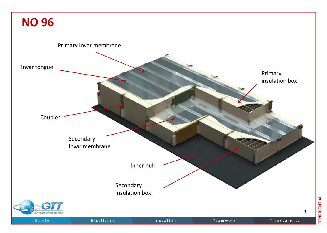
Primary Invar membrane
Primary insulation box
Secondary Invar membrane
Inner hull
Secondary insulation box
Invar tongue
Coupler
NO 96
7

CO
NF
IDE
NT
IAL
Mark III
Back Plywood
Secondary insulation layer (RPUF)
Composite secondary membrane (Triplex)
Primary insulation layer (RPUF)
Top plywood
Inner hull
Metallic insert
Top bridge pad Primary stainless steel membrane
Corner panel
Hardwood key
Resin ropes
Insulation panel
8

CO
NF
IDE
NT
IAL
GTT’s Applications for Commercial Vessels
9

CO
NF
IDE
NT
IAL
The Ship-owner’s Dilemma
Complying with new regulations regarding gas emissions reduction and remain competitive…
+
for those operating nearly exclusively in ECA zones, the decision must be taken rapidly
The alternatives are known : Running on HFO + scrubber + SCR Running on MDO / MGO Running on LNG
Parameters of the business plan equation : Technical feasibility (retrofit, newbuilding), reliability, CAPEX, OPEX, loss of
earnings…
February 6th 2013 3

CO
NF
IDE
NT
IAL
Why LNG?
Ecological benefits are obvious; straight compliance with any environmental rules.
Economic benefits still to be demonstrated but in Europe one can reasonably expect a price at an intermediate level between HFO and MGO (energy equivalent).
Other alternatives are either not completely proven ecologically (Scrubbers + SCR) or much too costly in OPEX (MDO/MGO).
February 6th 2013 4
CO
NF
IDE
NT
IAL
LNG Fueled ship
Parameters of the economic equation for the ship-owner :
• Price of LNG fuel ;
• Cost of supply chain infrastructure ;
• CAPEX ;
• OPEX ;
• Reduced available cargo space on an LNG fuelled ship as compared to the equivalent conventional ship.
February 6th 2013 5

CO
NF
IDE
NT
IAL
Small scale LNG infrastructure development
4/19/2013 13
Early Days (since 2000 abt)
Initiation of LNG used as fuel for ships initiated by Norway
Small LNG terminals and local storage on the coast line
Small volumes (on ferries and PSV < 500 m3)
Very local and dedicated logistics (trucks, very small LNG ships, e.g: Knutsen Pioneer)
Type-C tanks (pressurized tanks all along the supply chain)

CO
NF
IDE
NT
IAL
Next phase (starting 2015 and onwards)
Infrastructure building up in US and Europe (various drivers for that)
Volumes getting larger and larger: more ships and larger ships using LNG as fuel (not only ECA areas depending on the LNG price trend)
Larger tank capacities
Need for better efficiency in the supply chain
Greater use of low pressure containment system Particularly membrane technologies
4/19/2013 14
Small scale LNG infrastructure development

CO
NF
IDE
NT
IAL
Membrane Type Bunkering Solutions
Retrofit of a Container vessel New section includes: - a 5.000 m3 LNG tank, - a gas preparation room and - additional 100 TEU
Newbuild Ropax vessel - 1.700 m3 LNG tank - Gas preparation room
15

CO
NF
IDE
NT
IAL
16
Membrane Type Bunkering Solutions
Offshore storage & bunker station
Ship-to-Ship transfer system
Small Land Storage Tanks

CO
NF
IDE
NT
IAL
17
Small and Mid-scale LNG Carriers
Aman Sendai
Surya Satsuma
Under development
32,000 m3 LNG Feeder
16,500 m3 Shallow Draft LNGCs
In Service

CO
NF
IDE
NT
IAL
Main advantages of membrane technology
4/19/2013 18

CO
NF
IDE
NT
IAL
Main advantages of membrane technology Cargo space reduction on LNG fuelled ships
Rules imposing constraints on location of LNG tank onboard : Distance from side shell (B/5 as basis from IGF code) ; Requirement for cofferdams ; No LNG directly underneath passenger accommodation space.
Increased volume of required liquid To achieve same autonomy as conventional ship ; Equivalent onboard energy stored ; => Requires 1,6 to 1,7 more liquid volume compare with HFO or distillates.
Space for : insulation inspection Fuel Gas handling and supply system (FGHSS).
The larger the ship and/or the storage tanks,
the smaller the relative loss of cargo space
19

CO
NF
IDE
NT
IAL
Example of loss of cargo space
Loss of 450 TEU
LNG fuelled 16000 TEU mega container ship
Source: GTT
February 6th 2013 7

CO
NF
IDE
NT
IAL
Fuel CS & HS space occupied onboard
HFO LNG type A/B
LNG type C LNG Membrane
HS
Deadspace, inspection
CS
Liquid
- Main assumptions : Tanks integrated inside hull; same energy equivalent stored (same autonomy) for a typical passenger ferry.
- In reality, if running on DF engines, some HFO/MDO capacity + associated systems shall remain onboard increasing further the wasted space.
Vo
lum
e sp
ace
on
bo
ard
Source: GTT
February 6th 2013 8

CO
NF
IDE
NT
IAL
Weight Advantage
February 6th 2013 16
Bunker ship 4000 m3 LNG; 1000 m3 MDO
Type C design Membrane design
LOA 106 m 90 m
LBP 99,8 m 85,9 m
Breadth 16,5 m 15,7 m
Depth 9,0 m 9,4 m
Design Draught 5,1 m 5,0 m
Cb 0,75 0,77
Lightship weight 3520 t 2410 t
Design DWT 2900 dwt 2919 dwt
V LNG cargo tanks (100%) 4080 m3 4080 m3
Max filling level in LNG tank 98% 98%
V MDO cargo tanks (100%) 1000 m3 1000 m3
Service speed (85% MCR, 15% sea margin) 12,0 knots 12,0 knots
MCR (propulsion only) 2740 kW 2420 kW

CO
NF
IDE
NT
IAL
16,500 m3 Shallow Draft LNG carrier
23

CO
NF
IDE
NT
IAL
Other Advantages of Membrane solutions
Lighter and smaller ship means cheaper ship (for same cargo capacity in volume and deadweight)
Cheapest solution per m3 for large tanks (> 1.000 m3) either as cargo tank or fuel tank
Unrivaled track record for LNG transportation at sea
Possibility to create quite complex shape to better fit the available space on board
Low pressure means also low temperature of LNG: Because membrane is operating at low pressure (<700 mbarg), temperature is kept low (around -160°C) which is of utmost importance at delivery to end user.
Membrane presents the optimized solution in term of cost and seize for big volumes
4/19/2013 24

CO
NF
IDE
NT
IAL
4/19/2013 25
Addressing the main concerns

CO
NF
IDE
NT
IAL
Sloshing
Membrane system can withstand very high loads
Extensive model testing is carried out for each project by GTT using specific test facility (Hexapod)
For small LNG carriers which trade will mainly be coastal, the potential mass of liquid in tanks in case of partial filling will not be sufficient to generate:
significant sloshing loads
loss of stability beyond acceptable limits (IMO criteria)
Not even speaking about river or port activities for LNG river barges or LNG bunker ships/barges
4/19/2013 26

CO
NF
IDE
NT
IAL
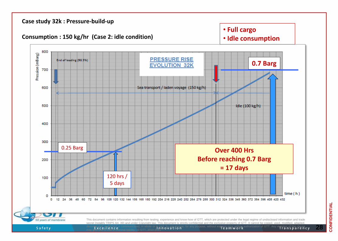
Pressure Build-up; BOG management
Natural Boil Off if not consumed accumulates in the upper part of the tank
For atmospheric pressure tanks (membrane, type A, B), this boil off has to be handled
Increased thermal performance of insulation and higher pressure (up to 700 mbar) allows for a reasonable autonomy in most of cases
4/19/2013
27
CO
NF
IDE
NT
IAL
28
Case study 32k : Pressure-build-up Consumption : 150 kg/hr (Case 2: idle condition)
This document contains information resulting from testing, experience and know-how of GTT, which are protected under the legal regime of undisclosed information and trade
secret (notably TRIPS Art. 39) and under Copyright law. This document is strictly confidential and the exclusive property of GTT. It cannot be copied, used, modified, adapted,
disseminated, published or communicated, in whole or in part, by any means, for any purpose, without express prior written authorization of GTT. Any violation of this clause
may give rise to civil or criminal liability - © GTT, 2010-2011
Over 400 Hrs Before reaching 0.7 Barg
= 17 days
• Full cargo • Idle consumption
120 hrs / 5 days
0.7 Barg
0.25 Barg

CO
NF
IDE
NT
IAL
Conclusion
Membrane technology is well adapted to all storage application all along the small scale supply chain:
- LNG feeder
- LNG river barges
- LNG bunker ships / barges
- Small – medium LNG land storage
Very efficient solutions (compact and optimized ships) are expected using membrane technology for the upcoming development of the small scale infrastructure development
4/19/2013 29


