USDA FOREST SERVICE RESEARCH PAPER
FPL 220 1973
LOCAL BUCKLING OF ORTHOTROPIC
TRUSS-CORE SANDWICH
U . S . Department of Agriculture - Forest Service -Forest Products Laboratory -Madison, Wis.
THIS REPORT IS ONE OF A SERIES ISSUED IN COOPERATION WITH THE
MIL-HDBK-23 WORKING GROUP ON STRUCTURAL SANDWICH COMPOSITES FOR AEROSPACE VEHICLES
OF THE DEPARTMENTS OF THE AIR FORCE AND NAVY, AND FEDERAL AVIATION ADMINISTRATION
ABSTRACT This report analyzes the local buckling mode of compression
failure of truss-core sandwich when compressed parallel to core flutes. A mathematical analysis is presented for the general case of similar equal orthotropic facings and dis-similar core of unequal sheet thickness. Seven cases are cal-culated and buckling curves are presented. The results are found to be applicable to dissimilar facings.
This paper is another in the series issued in cooperationwith the Military Handbook 23 Working Group on Structural Sandwich Composites for Aerospace Vehicles of the Departmentsof the Air Force and Navy, and the Federal Aviation Administration under U.S. Air Force DO F 33-615-72-M-5001.
----
LOCAL BUCKLING OF ORTHOTROPIC TRUSS-CORE SANDWlCH
By JOHN J. ZAHN, Engineer
Forest Products laboratory1, Forest Service U.S. Department of Agriculture
INTRODUCTION When face sheets are bonded to a corrugated core, the resul t ing construct ion is cal led a
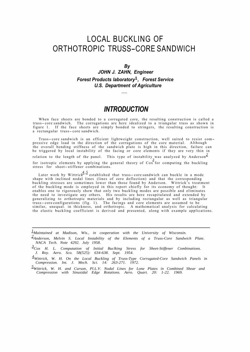
t russ- core sandwich. The corrugat ions are here ideal ized to a t r iangular t russ as shown in f igure 1. I f the face sheets are s imply bonded to s t r ingers , the resul t ing construct ion is a rectangular t russ- core sandwich.
Truss- core sandwich is an eff ic ient l ightweight construct ion, wel l sui ted to res is t com-pressive edge load in the direct ion of the corrugat ions of the core mater ia l . Al though the overal l bending s t i f fness of the sandwich plate is high in this direct ion, fa i lure can be t r iggered by local instabi l i ty of the facing or core e lements i f they are very thin in
2re la t ion to the length of the panel . This type of instabi l i ty was analyzed by Anderson 3
for isotropic e lements by applying the general theory of Cox for computing the buckl ing s t ress for sheet- st i f fener combinat ions.
Later work by Wit t r ick4 , 5
establ ished that t russ- core sandwich can buckle in a mode shape with incl ined nodal l ines ( l ines of zero def lect ion) and that the corresponding buckl ing s t resses are sometimes lower than those found by Anderson. Wit t r ick’s t reatment of the buckl ing mode is employed in this report chief ly for i ts economy of thought : I t enables one to r igorously show that only two buckl ing modes are possible and el iminates the need to invest igate any others . His resul ts are here recapi tulated and extended by general iz ing to or thotropic mater ia ls and by including rectangular as wel l as t r iangular t russ- core configurat ions (f ig . 1) . The facings and core elements are assumed to be s imilar , unequal . in thickness , and or thotropic . A mathematical analysis for calculat ing the elast ic buckl ing coeff ic ient is der ived and presented, a long with example appl icat ions.
1Maintained at Madison, Wis., in cooperation with the University of Wisconsin. 2Anderson, Melvin S. Local Instability of the Elements of a Truss-Core Sandwich Plate.
NACA Tech. Note 4292. July 1958. 3Cox H. L. Computation of Initial Buclking Stress for Sheet-Stiffener Combinations.
J. Roy. Aero. Sco. 58(525): 634-638. Sept. 1954. 4Wittrick, W. H. On the Local Buckling of Truss-Type Corrugated-Core Sandwich Panels in
Compression. Int. J. Mech. Sci. 14: 263-271. 1972. 5Wittrick, W. H. and Curson, Pl.L.V. Nodal Lines for Lone Plates in Combined Shear and
Compression with Sinusidal Edge Rotations. Aero. Quart. 20: 1-22. 1969.
Figure 1.--Cross sections of truss-core sandwich. M 141 274
Figure 2.--Long strip of width b under axial compression. M 141 275
Figure 3. --Buckling mode shape for triangular truss-core. M 141 486
FPL 220 2

NOTATION
A, B , C , D i n t e g r a t i o n c o n s t a n t s . a wavelength of b u c k l e i n x- d i r e c t i o n . b w id th of s t r i p . s u b s c r i p t 0 deno te s co re .
C 2 , C3 edge- ro t a t i on s t i f f n e s s e s , c o r e e lement .
D x, Dy , Dxy f l e x u r a l and s h e a r r i g i d i t i e s . See e q u a t i o n s ( 3 ) , ( 4 ) , and ( 5 ) . Ex, Ey moduli o f e l a s t i c i t y .
F 2 , F3 edge- ro t a t i on s t i f f n e s s e s , f a c e e lement .
f x compressive s t r e s s i n x- d i r ec t i on .
b u c k l i n g s t r e s s i n f a c i n g m a t e r i a l .
G s h e a r modulus of e l a s t i c i t y , x y
H see e q u a t i o n ( 2 ) . k b u c k l i n g c o e f f i c i e n t . See e q u a t i o n ( 5 0 ) . My edge bending moment.
S2 , S3 edge r o t a t i o n s t i f f n e s s e s . See e q u a t i o n s ( 2 3 ) , ( 2 4 ) , ( 2 6 ) , ( 3 0 ) , ( 31 ) ,
and ( 3 2 ) . t t h i c k n e s s . W l a t e r a l d e f l e c t i o n from x-y p l a n e . x, y c o o r d i n a t e axes . See f i g u r e 2 . Y f u n c t i o n of y . α, β see e q u a t i o n s ( 5 4 ) and ( 5 5 ) . α1, α2 r o o t s of c h a r a c t e r i s t i c e q u a t i o n ,
τ, γ s e e e q u a t i o n s (13) and ( 1 4 ) . δ s e e equa t ion ( 1 6 ) . η see e q u a t i o n (17 ) . θ a n g l e of t r u s s co re . See f i g u r e 1. µ xy, µ yx P o i s s o n ' s r a t i o s .
λ 1 - µ µxy yx
ρ a / b , a s p e c t r a t i o o f f a c e buck l e . ang l e of r o t a t i o n a t j u n c t i o n o f e lements . See f i g u r e 3 .
ANALYSIS Cox 3 der ived the edge rotat ion s t i f fness of paral le l isotropic s t r ips under axial com-
pression. Such s t i f fness is def ined as the rat io of edge moment to edge rotat ion of a hinged la teral edge (see f ig . 2) . This s t i f fness depends upon the axial load. I f several paral le l s t r ips are r igidly joined along a common l ine, the resis tance of the s t ructural to local rotat ion ahcut the common l ine wil l a lso depend on the axial load. In fact , i t will vanish at the cr i t ical load. This is the essence of Cox' method of calculat ing cr i t ical local buckl ing loads of such s t ructures as polygonal tubes or , as in this appl icat ion, of t russ- core sandwich. The f i rs t s tep is to calculate the edge rotat ion s t i f fness of a s ingle s t r ip .
3
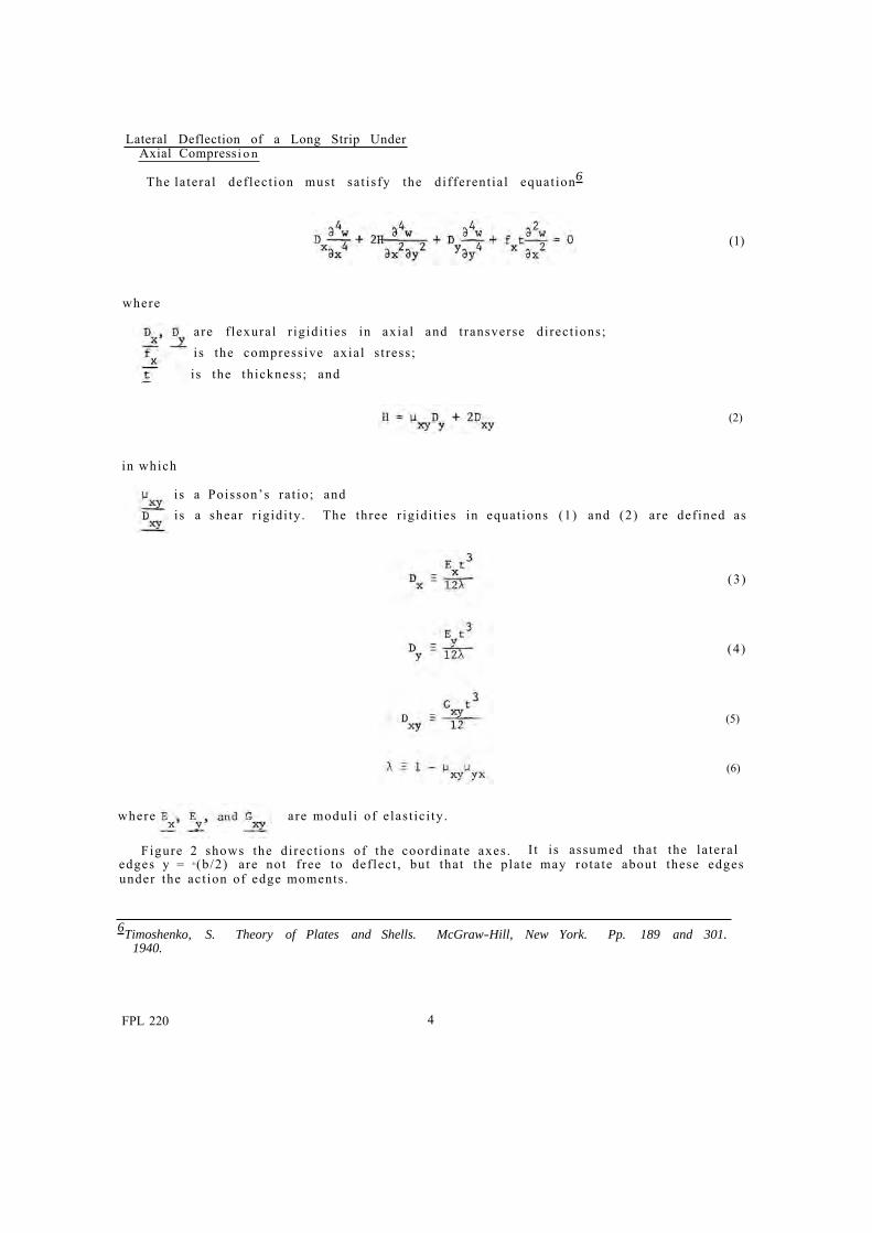
Lateral Deflection of a Long Strip Under Axial Compress i o n
The la teral def lect ion must sat isfy the different ia l equat ion6
(1)
where
are f lexural r igidi t ies in axial and t ransverse direct ions; is the compressive axial s t ress ; is the thickness; and
(2)
in which
is a Poisson’s ra t io; and is a shear r igidi ty . The three r igidi t ies in equat ions (1) and (2) are def ined as
(3)
(4)
(5)
(6)
where are moduli of e las t ic i ty .
Figure 2 shows the direct ions of the coordinate axes . I t i s assumed that the la teral edges y = ±(b/2) are not f ree to def lect , but that the plate may rotate about these edges under the act ion of edge moments .
6Timoshenko, S. Theory of Plates and Shells. McGraw-Hill, New York. Pp. 189 and 301. 1940.
FPL 220 4
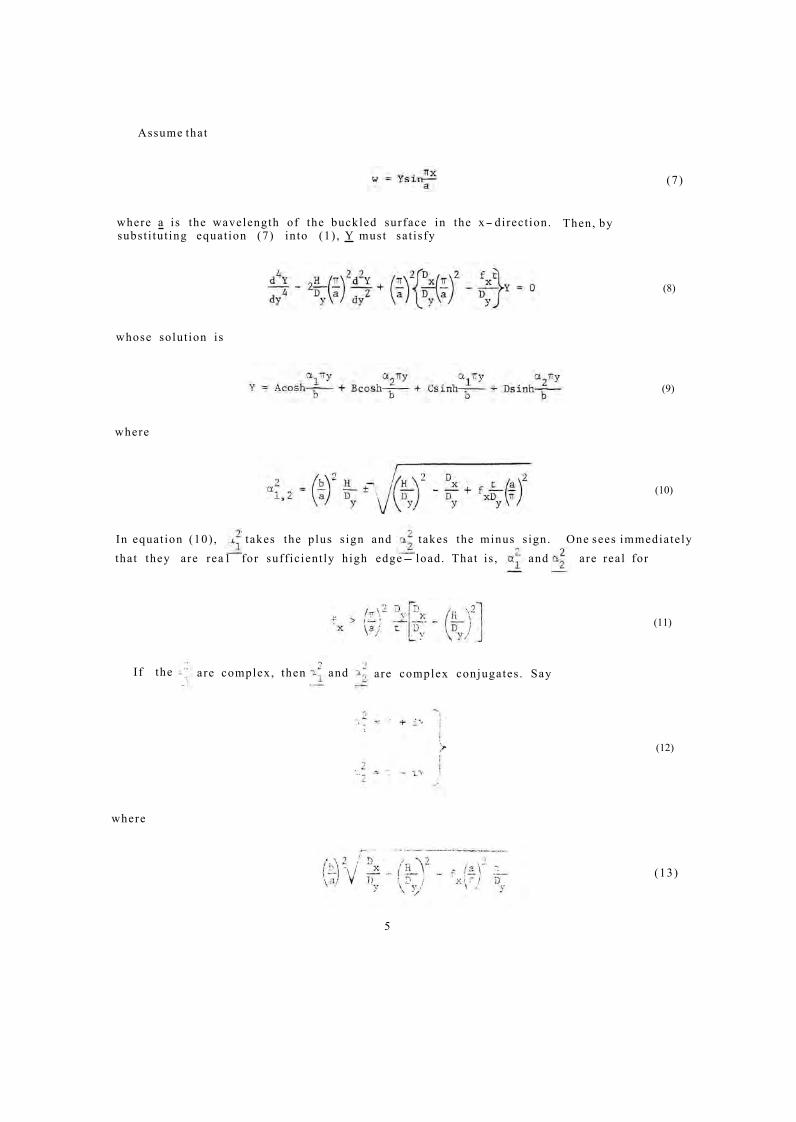
Assume that
where a is the wavelength of the buckled surface in the x- direct ion. subst i tut ing equat ion (7) into (1) , Y must sat isfy
whose solut ion is
(7)
Then, by
(8)
(9)
where
In equat ion (10) , takes the plus s ign and takes the minus s ign.
(10)
One sees immediately that they are rea1 for suff ic ient ly high edge- load. That is , and are real for
(11)
(12)
(13)
I f the are complex, then and are complex conjugates . Say
where
5
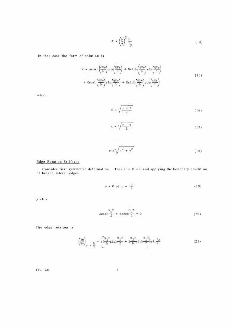
(14)
In that case the form of solut ion is
(15)
where
(16)
(17)
(18)
Edge Rotat ion St i f fness
Consider f i rs t symmetr ic deformation. Then C = D = 0 and applying the boundary condi t ion of hinged la teral edges
(19)
y i e l d s
(20)
(21)
The edge rotat ion is
FPL 220 6
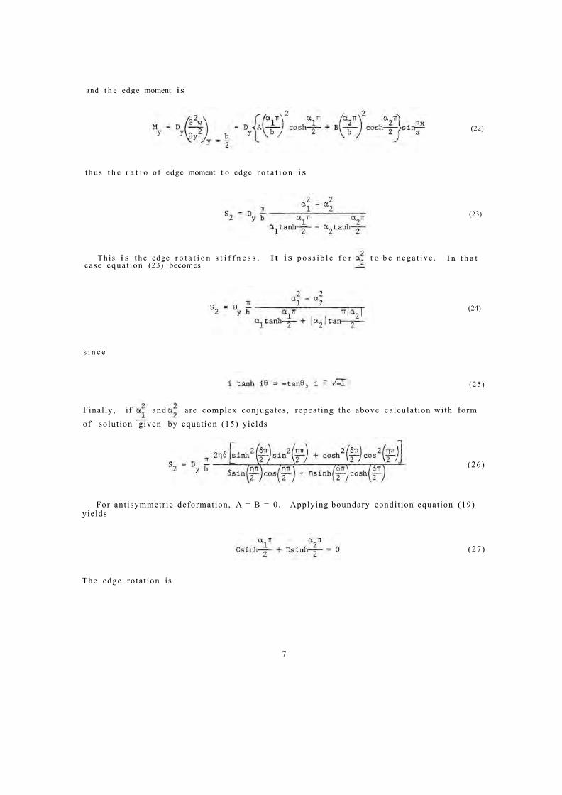
a n d t h e edge moment is
(22)
t h u s t h e r a t i o o f edge moment t o edge r o t a t i o n is
(23)
Th i s i s t h e edge r o t a t i o n s t i f f n e s s . It is p o s s i b l e f o r t o b e n e g a t i v e . I n t h a t case e q u a t i o n (23) becomes
(24)
s i n c e
( 2 5 )
Final ly , i f and by equat ion (15) yields
are complex conjugates , repeat ing the above calculat ion with form of solut ion given
(26)
For ant isymmetr ic deformation, A = B = 0. Applying boundary condi t ion equat ion (19) yields
(27)
The edge rotat ion is
7
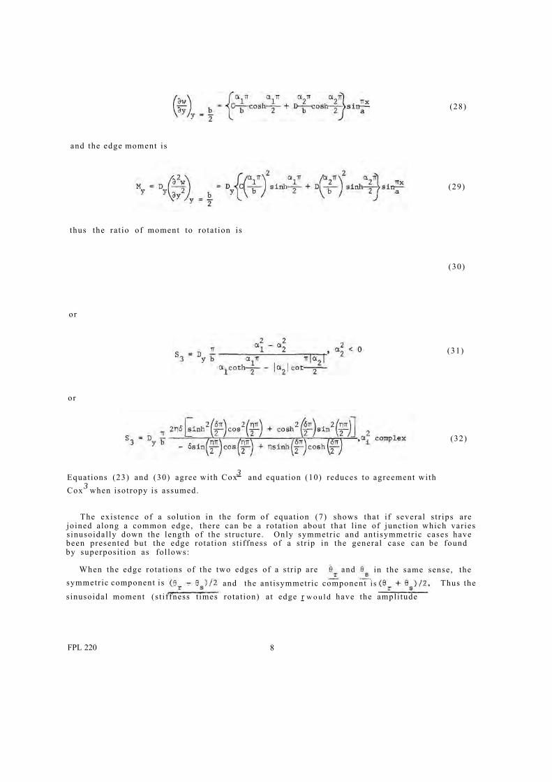
(28)
and the edge moment is
(29)
thus the rat io of moment to rotat ion is
(30)
or
(31)
or
(32)
3Equat ions (23) and (30) agree with Cox and equat ion (10) reduces to agreement with Cox 3 when isotropy is assumed.
The exis tence of a solut ion in the form of equat ion (7) shows that i f several s t r ips are joined along a common edge, there can be a rotat ion about that l ine of junct ion which var ies s inusoidal ly down the length of the s t ructure . Only symmetr ic and ant isymmetr ic cases have been presented but the edge rotat ion s t i f fness of a s t r ip in the general case can be found by superposi t ion as fol lows:
When the edge rotat ions of the two edges of a s t r ip are and in the same sense, the symmetr ic component is and the ant isymmetr ic component i s Thus the s inusoidal moment (s t i f fness t imes rotat ion) a t edge r w o u l d have the ampli tude
FPL 220 8
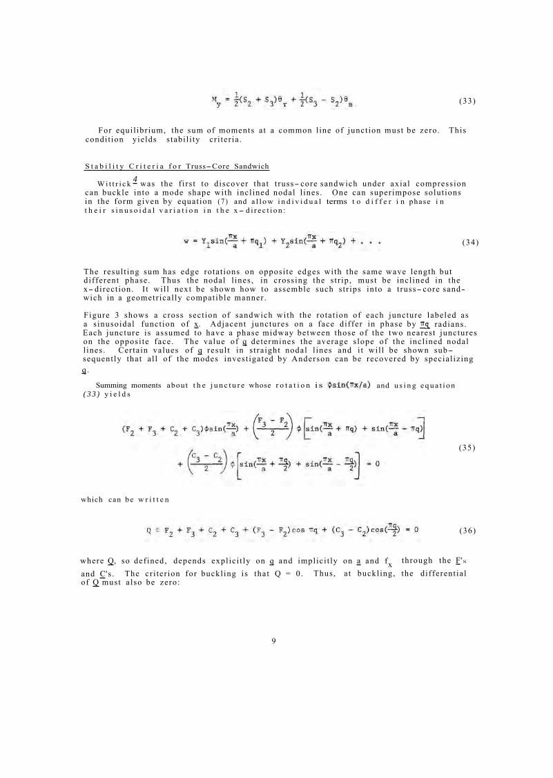
(33)
For equi l ibr ium, the sum of moments a t a common l ine of junct ion must be zero. This condi t ion yields s tabi l i ty cr i ter ia .
S t a b i l i t y C r i t e r i a f o r Truss-Core Sandwich
W i t t r i c k 4 was the f i rs t to discover that t russ- core sandwich under axial compression can buckle into a mode shape with incl ined nodal l ines . One can superimpose solut ions in the form given by equat ion ( 7 ) and a l l o w i n d i v i d u a l terms t o d i f f e r i n phase i n t h e i r s i n u s o i d a l v a r i a t i o n i n t h e x- d i r e c t i o n :
(34)
The resul t ing sum has edge rotat ions on opposi te edges with the same wave length but different phase. Thus the nodal l ines , in crossing the s t r ip , must be incl ined in the x- direct ion. I t wi l l next be shown how to assemble such s t r ips into a t russ- core sand-wich in a geometr ical ly compatible manner .
Figure 3 shows a cross sect ion of sandwich with the rotat ion of each juncture labeled as a s inusoidal funct ion of x. Adjacent junctures on a face differ in phase by radians. Each juncture is assumed to have a phase midway between those of the two nearest junctures on the opposi te face. The value of q determines the average s lope of the incl ined nodal l ines . Certain values of q resul t in s t ra ight nodal l ines and i t wi l l be shown sub-sequent ly that a l l of the modes invest igated by Anderson can be recovered by special iz ing q .
Summing moments about t h e j u n c t u r e whose r o t a t i o n i s and u s i n g e q u a t i o n ( 3 3 ) y i e l d s
(35)
which can be w r i t t e n
(36)
where Q, so def ined, depends expl ic i t ly on q and implici t ly on a and f x through the F'S
and C's . The cr i ter ion for buckl ing is that Q = 0. Thus, a t buckl ing, the different ia l of Q must a lso be zero:
9
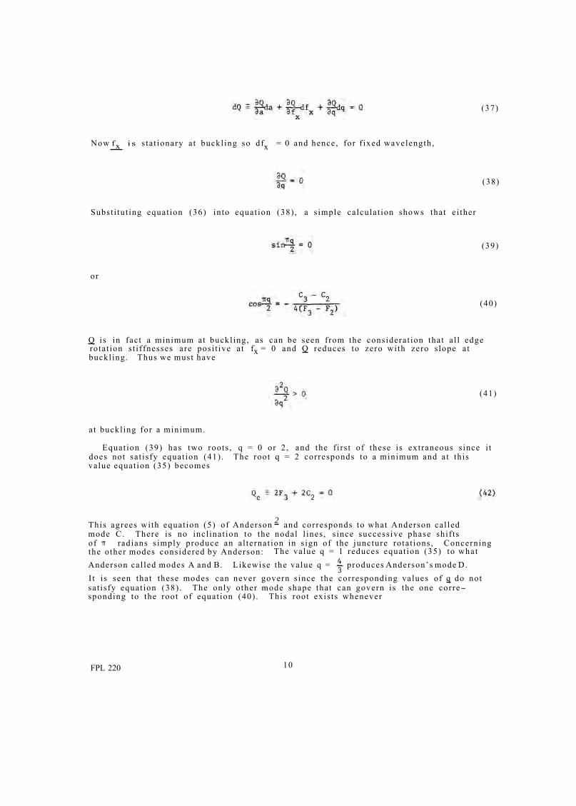
(37)
Now f x i s s ta t ionary at buckl ing so dfx = 0 and hence, for f ixed wavelength,
(38)
Subst i tut ing equat ion (36) into equat ion (38) , a s imple calculat ion shows that e i ther
(39)
or
(40)
Q is in fact a minimum at buckl ing, as can be seen from the considerat ion that a l l edgerotat ion s t i f fnesses are posi t ive at fx = 0 and Q reduces to zero with zero s lope at buckl ing. Thus we must have
(41)
a t buckl ing for a minimum.
Equat ion (39) has two roots , q = 0 or 2 , and the f i rs t of these is extraneous s ince i t does not sat isfy equat ion (41) . The root q = 2 corresponds to a minimum and at this value equat ion (35) becomes
This agrees with equat ion (5) of Anderson 2 and corresponds to what Anderson cal led mode C. There is no incl inat ion to the nodal l ines , s ince successive phase shif ts of radians s imply produce an al ternat ion in s ign of the juncture rotat ions, Concerning the other modes considered by Anderson: The value q = 1 reduces equat ion (35) to what Anderson cal led modes A and B. Likewise the value q = produces Anderson’s mode D. I t i s seen that these modes can never govern s ince the corresponding values of q do not sat isfy equat ion (38) . The only other mode shape that can govern is the one corre-sponding to the root of equat ion (40) . This root exis ts whenever
FPL 220 10
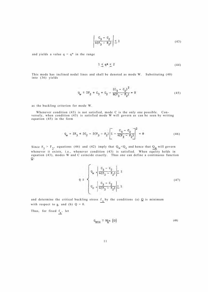
and yields a value q = q* in the range
This mode has incl ined nodal l ines and shal l be denoted as mode W. Subst i tut ing (40) into (36) yields
as the buckl ing cr i ter ion for mode W.
Whenever condi t ion (43) is not sat isf ied, mode C is the only one possible . Con-versely, when condi t ion (43) is sat isf ied mode W wil l govern as can be seen by wri t ing equat ion (45) in the form
(43)
(44)
(45)
(46)
Since F3 whenever i t exis ts , i .e . , whenever condi t ion (43) is sat isf ied.
> F2, equat ions (46) and (42) imply that Qw <Q c and hence that Qw wil l govern When equl i ty holds in
equat ion (43) , modes W and C coincide exact ly . Thus one can def ine a cont inuous funct ion Q :
(47)
and determine the cr i t ical buckl ing s t ress f by the condi t ions (a) Q is minimum x with respect to a, and (b) Q = 0.
Thus, for f ixed fx’ le t
(48)
11

- -Figure 4. Deteminant versus a and k. An example showing typical behavior . M 141 488 b
Figu re 5 . -- Buckl ing node s h a p e f o r r e c t a n g u l a r t r u s s- c o r e . M 141 487
FPL 220 12
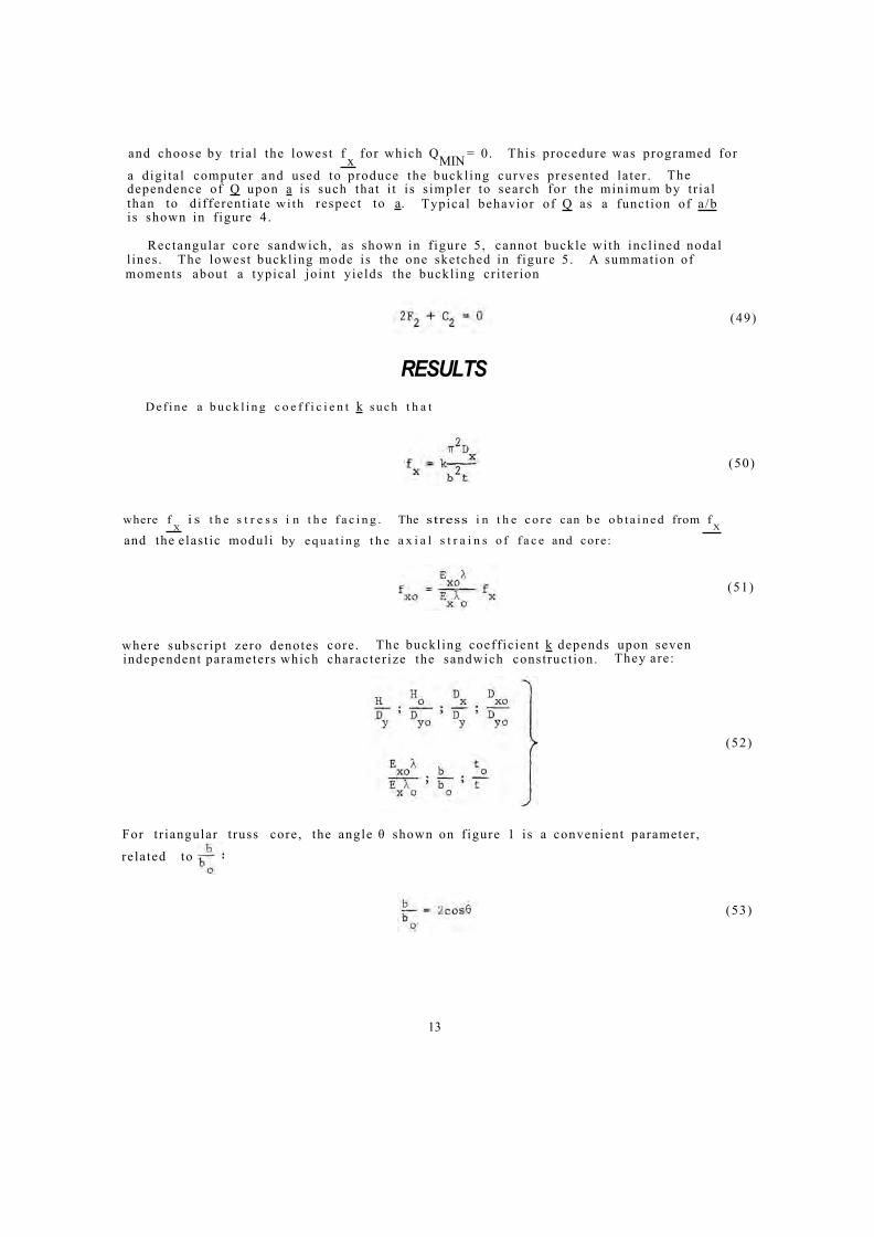
and choose by t r ia l the lowest f x for which QMIN = 0. This procedure was programed for
a digi ta l computer and used to produce the buckl ing curves presented la ter . The dependence of Q upon a is such that i t i s s impler to search for the minimum by t r ia l than to different ia te with respect to a. Typical behavior of Q as a funct ion of a /b is shown in f igure 4.
Rectangular core sandwich, as shown in f igure 5, cannot buckle with incl ined nodal l ines . The lowest buckl ing mode is the one sketched in f igure 5. A summation of moments about a typical joint yields the buckl ing cr i ter ion
RESULTS Def ine a b u c k l i n g c o e f f i c i e n t k such t h a t
where f i s t h e s t r e s s i n t h e f a c i n g . The stress i n t h e c o r e can b e o b t a i n e d from f X X
and the elast ic moduli by e q u a t i n g t h e a x i a l s t r a i n s o f f a c e and core:
where subscr ipt zero denotes core . The buckl ing coeff ic ient k depends upon seven independent parameters which character ize the sandwich construct ion. They are:
For t r iangular t russ core , the angle θ shown on f igure 1 is a convenient parameter ,
re la ted to
13
(49)
(50)
(51)
(52)
(53)
The parameter (E xoλ ) / (Ex λo) is an independent parameter only when core and face are of diss imilar mater ia ls .
Seven cases of t russ- core sandwich were invest igated and the resul ts are presented as carpet plots of the cr i t ical buckl ing parameter k versus t 0/ t and θ in f igures 6 to 14. This type of plot is designed to faci l i ta te interpolat ion. In fact , the abscissa is a l inear combinat ion of t
0 / t and θ so that both var iables can be interpolated horizontal ly .
Figure 15 shows an interpolat ion example on an enlarged port ion of f igure 6.
Two types of or thotropic glass fabr ic laminate were chosen as facing and core mater ia l , one with Ex not equal to Ey ( type 1) and one with E x and E y.equal . The unequal-E laminate was used in both possible or ienta t ions , yielding the three types of mater ia l shown in table 1 . This table shows the mater ia l parameters def ined in this report and also the commonly employed parameters α and β which are def ined as
The relat ionship between the two sets of parameters is easi ly seen to be
(56)
(57)
Table 2 summarizes the s ix cases s tudied. Cases 1 , 2 , and 3 have core and facing of s imilar mater ia ls . Cases 4 and 5 have core and facing diss imilar by using the unequal-E laminate for both with the core mater ia l rotated 90" re la t ive to the facing mater ia l . Case 6 employs an equal-E facing and an unequal- , core . In this case an addi t ional parameter must he specif ied, namely
(58)
and therefore three carpet plots were calculated corresponding to three values of this parameter . In cases 4 and 5 this parameter was automatical ly determined by the fact that core and facing mater ia ls were not t ruly different but were the same mater ia l rotated 90°.
FPL 220 14

Case 7 is isotropic facing and core. Comparison with Anderson’s resul ts 2 show that cr i t ical buckl ing s t resses associated with mode W are never more than 2 percent less than those calculated by Anderson.
No calculculat ions were made for rectangular t russ .
Dissimilar Fac ings
Anderson 2 pointed out that his results were applicable to dissimilar facings. The same remark can be made here. His mode A, which has one facing remaining flat as if infinitely rigid, is surely the governing mode when one facing is stiffer by a suf-ficient amount. Investigation shows that the buckling load corresponding to mode A is never more than about 6 percent greater than the buckling loads presented here. Thus one would be only slightly conservative to apply these results to dissimilar facings, using the properties of the softer facing to calculate the material parameters.
Table 1.--Three types of glass fabric laminate. 1 Commonly employed material parameters α and β are shown for reference
Table 2.--Six cases of orthotropic truss-core sandwich for which buckling curves were computed
15
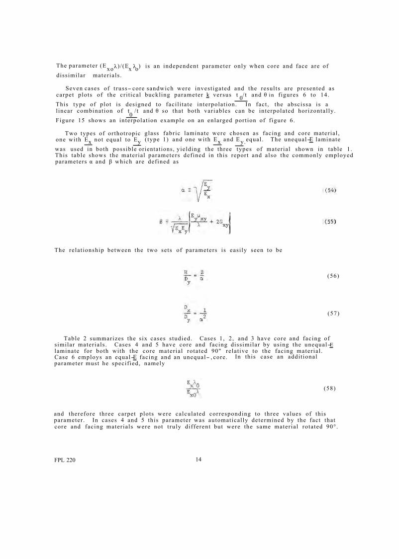
- -Figure 6. Buckl ing coeff ic ients for case 1. For facing and core, α = 1 .5 , β = 0 .6 . M 141 496
Figre 7.- -Buckl ing coeff ic ients for case 2. For faceing and core, α = 1 , β = 0 .6 . M 141 497
FPL 220 16
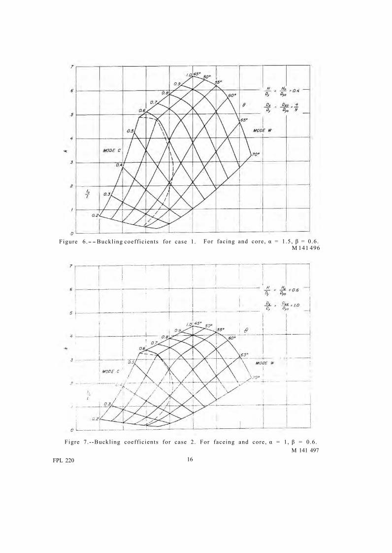
Figure 8.- - Buckl ingcoeff ic ients for case 3. For facing and core, α = 2/3, β = 0 .6 . M 141 494
Figure 9.- -Buckl ing coeff ic ients for case 4. For facing, α = 2/3; for core , β = 1 .5; for both, β = 0 .6 . M 141 493
17
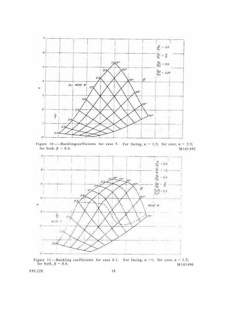
- -Figure 10. Buckl ingcoeff ic ients for case 5. For facing, α = 1 .5; for core , α = 2/3; for both, β = 0 .6 . M 141 492
Figure 11.- -Buckl ing coeff ic ients for case 6.1. For facing, α = 1; for core , α = 1 .5; for both, β = 0 .6 . M 141 490
FPL 220 18
- -
--
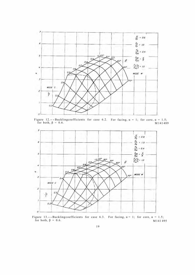
Figure 12. Buckl ingcoeff ic ients for case 6.2. For facing, α = 1; for core , α = 1 .5; for both, β = 0 .6 . M 141 489
Figure 13. Buckl ing coeff ic ients for case 6.3. For facing, α = 1; for core , α = 1 .5; for both, β = 0 .6 . M 141 495
19
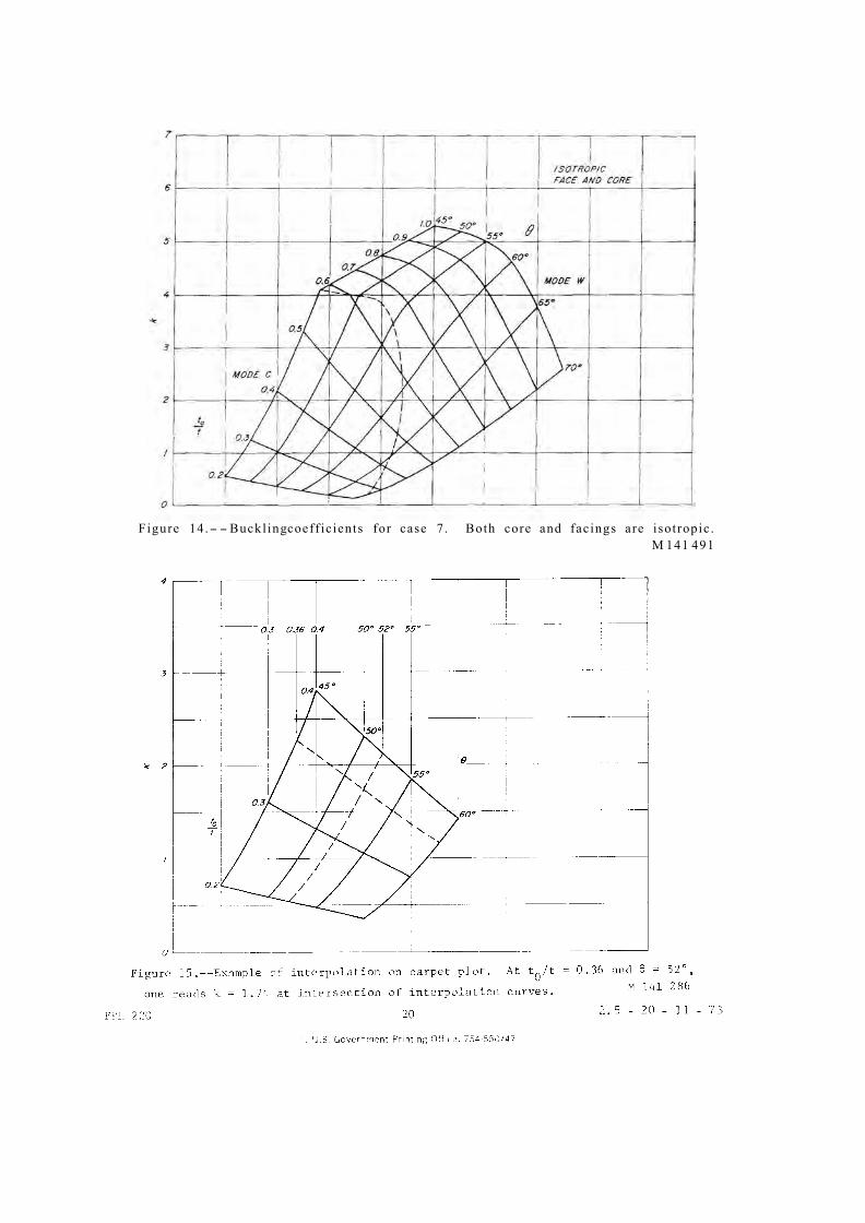
- -Figure 14. Buckl ingcoeff ic ients for case 7. Both core and facings are isotropic . M 141 491


