
DTG 130 Eco.NOxLow temperature gas boiler
ELITEC
Installation and Service Manual
300002915-001-E
EN

Declaration of conformity
The appliance complies with the standard model described in declaration of compliance . It is manufactured and distributed pursuant to therequirements of european directives. The original of the declaration of compliance is available from the manufacturer.
L000148-A
2 DTG 130 Eco.NOx 01/02/11 - 300002915-001-E

Contents
1 Introduction . . . . . . . . . . . . . . . . . . . . . . . . . . . . . . . . . . . . . . . . . . . . . . . . . . . . . . . . . . . . . . . . . . . . . . . . . . . . .51.1 Used symbols . . . . . . . . . . . . . . . . . . . . . . . . . . . . . . . . . . . . . . . . . . . . . . . . . . . . . . . . . . . . . . . . . . . . . . . . . . . . . . . . . . . . . . . . . . .51.2 General . . . . . . . . . . . . . . . . . . . . . . . . . . . . . . . . . . . . . . . . . . . . . . . . . . . . . . . . . . . . . . . . . . . . . . . . . . . . . . . . . . . . . . . . . . . . . . . .51.3 Homologations . . . . . . . . . . . . . . . . . . . . . . . . . . . . . . . . . . . . . . . . . . . . . . . . . . . . . . . . . . . . . . . . . . . . . . . . . . . . . . . . . . . . . . . . . .6
1.3.1 User country. . . . . . . . . . . . . . . . . . . . . . . . . . . . . . . . . . . . . . . . . . . . . . . . . . . . . . . . . . . . . . . . . . . . . . . . . . . . . . . . . . . . . .71.3.2 Directive 97/23/EC . . . . . . . . . . . . . . . . . . . . . . . . . . . . . . . . . . . . . . . . . . . . . . . . . . . . . . . . . . . . . . . . . . . . . . . . . . . . . . . . .7
2 Safety instructions and recommendations. . . . . . . . . . . . . . . . . . . . . . . . . . . . . . . . . . . . . . . . . . . . . . . . . . . .82.1 Safety instructions . . . . . . . . . . . . . . . . . . . . . . . . . . . . . . . . . . . . . . . . . . . . . . . . . . . . . . . . . . . . . . . . . . . . . . . . . . . . . . . . . . . . . . .82.2 Recommendations . . . . . . . . . . . . . . . . . . . . . . . . . . . . . . . . . . . . . . . . . . . . . . . . . . . . . . . . . . . . . . . . . . . . . . . . . . . . . . . . . . . . . . .8
3 Technical description . . . . . . . . . . . . . . . . . . . . . . . . . . . . . . . . . . . . . . . . . . . . . . . . . . . . . . . . . . . . . . . . . . . . .93.1 General description . . . . . . . . . . . . . . . . . . . . . . . . . . . . . . . . . . . . . . . . . . . . . . . . . . . . . . . . . . . . . . . . . . . . . . . . . . . . . . . . . . . . . .93.2 Technical characteristics . . . . . . . . . . . . . . . . . . . . . . . . . . . . . . . . . . . . . . . . . . . . . . . . . . . . . . . . . . . . . . . . . . . . . . . . . . . . . . . . .103.3 Main parts . . . . . . . . . . . . . . . . . . . . . . . . . . . . . . . . . . . . . . . . . . . . . . . . . . . . . . . . . . . . . . . . . . . . . . . . . . . . . . . . . . . . . . . . . . . . .113.4 Operating principle . . . . . . . . . . . . . . . . . . . . . . . . . . . . . . . . . . . . . . . . . . . . . . . . . . . . . . . . . . . . . . . . . . . . . . . . . . . . . . . . . . . . . .12
4 Installation . . . . . . . . . . . . . . . . . . . . . . . . . . . . . . . . . . . . . . . . . . . . . . . . . . . . . . . . . . . . . . . . . . . . . . . . . . . . .144.1 Regulations governing installation . . . . . . . . . . . . . . . . . . . . . . . . . . . . . . . . . . . . . . . . . . . . . . . . . . . . . . . . . . . . . . . . . . . . . . . . . .14
4.1.1 France . . . . . . . . . . . . . . . . . . . . . . . . . . . . . . . . . . . . . . . . . . . . . . . . . . . . . . . . . . . . . . . . . . . . . . . . . . . . . . . . . . . . . . . . .144.1.2 Germany . . . . . . . . . . . . . . . . . . . . . . . . . . . . . . . . . . . . . . . . . . . . . . . . . . . . . . . . . . . . . . . . . . . . . . . . . . . . . . . . . . . . . . .144.1.3 Switzerland. . . . . . . . . . . . . . . . . . . . . . . . . . . . . . . . . . . . . . . . . . . . . . . . . . . . . . . . . . . . . . . . . . . . . . . . . . . . . . . . . . . . . .154.1.4 Other countries. . . . . . . . . . . . . . . . . . . . . . . . . . . . . . . . . . . . . . . . . . . . . . . . . . . . . . . . . . . . . . . . . . . . . . . . . . . . . . . . . . .15
4.2 Package list . . . . . . . . . . . . . . . . . . . . . . . . . . . . . . . . . . . . . . . . . . . . . . . . . . . . . . . . . . . . . . . . . . . . . . . . . . . . . . . . . . . . . . . . . . .154.3 Mounting. . . . . . . . . . . . . . . . . . . . . . . . . . . . . . . . . . . . . . . . . . . . . . . . . . . . . . . . . . . . . . . . . . . . . . . . . . . . . . . . . . . . . . . . . . . . . .16
4.3.1 Position of the boiler. . . . . . . . . . . . . . . . . . . . . . . . . . . . . . . . . . . . . . . . . . . . . . . . . . . . . . . . . . . . . . . . . . . . . . . . . . . . . . .164.3.2 Ventilation . . . . . . . . . . . . . . . . . . . . . . . . . . . . . . . . . . . . . . . . . . . . . . . . . . . . . . . . . . . . . . . . . . . . . . . . . . . . . . . . . . . . . .164.3.3 Main dimensions . . . . . . . . . . . . . . . . . . . . . . . . . . . . . . . . . . . . . . . . . . . . . . . . . . . . . . . . . . . . . . . . . . . . . . . . . . . . . . . . .174.3.4 Assembling the appliance . . . . . . . . . . . . . . . . . . . . . . . . . . . . . . . . . . . . . . . . . . . . . . . . . . . . . . . . . . . . . . . . . . . . . . . . . .194.3.5 Levelling . . . . . . . . . . . . . . . . . . . . . . . . . . . . . . . . . . . . . . . . . . . . . . . . . . . . . . . . . . . . . . . . . . . . . . . . . . . . . . . . . . . . . . . .20
4.4 Hydraulic connections . . . . . . . . . . . . . . . . . . . . . . . . . . . . . . . . . . . . . . . . . . . . . . . . . . . . . . . . . . . . . . . . . . . . . . . . . . . . . . . . . . .214.4.1 Regulations . . . . . . . . . . . . . . . . . . . . . . . . . . . . . . . . . . . . . . . . . . . . . . . . . . . . . . . . . . . . . . . . . . . . . . . . . . . . . . . . . . . . .214.4.2 Hydraulic connection of the heating circuit. . . . . . . . . . . . . . . . . . . . . . . . . . . . . . . . . . . . . . . . . . . . . . . . . . . . . . . . . . . . . .214.4.3 Hydraulic connection of the water circuit for domestic use . . . . . . . . . . . . . . . . . . . . . . . . . . . . . . . . . . . . . . . . . . . . . . . . .214.4.4 Filling the system . . . . . . . . . . . . . . . . . . . . . . . . . . . . . . . . . . . . . . . . . . . . . . . . . . . . . . . . . . . . . . . . . . . . . . . . . . . . . . . . .224.4.5 Water treatment . . . . . . . . . . . . . . . . . . . . . . . . . . . . . . . . . . . . . . . . . . . . . . . . . . . . . . . . . . . . . . . . . . . . . . . . . . . . . . . . . .22
4.5 Gas connection. . . . . . . . . . . . . . . . . . . . . . . . . . . . . . . . . . . . . . . . . . . . . . . . . . . . . . . . . . . . . . . . . . . . . . . . . . . . . . . . . . . . . . . . .224.6 Connection to a chimney . . . . . . . . . . . . . . . . . . . . . . . . . . . . . . . . . . . . . . . . . . . . . . . . . . . . . . . . . . . . . . . . . . . . . . . . . . . . . . . . .234.7 Electrical connections. . . . . . . . . . . . . . . . . . . . . . . . . . . . . . . . . . . . . . . . . . . . . . . . . . . . . . . . . . . . . . . . . . . . . . . . . . . . . . . . . . . .234.8 Skeleton Diagrams . . . . . . . . . . . . . . . . . . . . . . . . . . . . . . . . . . . . . . . . . . . . . . . . . . . . . . . . . . . . . . . . . . . . . . . . . . . . . . . . . . . . . .23
5 Commissioning . . . . . . . . . . . . . . . . . . . . . . . . . . . . . . . . . . . . . . . . . . . . . . . . . . . . . . . . . . . . . . . . . . . . . . . . .245.1 Control panel . . . . . . . . . . . . . . . . . . . . . . . . . . . . . . . . . . . . . . . . . . . . . . . . . . . . . . . . . . . . . . . . . . . . . . . . . . . . . . . . . . . . . . . . . .245.2 Check points before commissioning. . . . . . . . . . . . . . . . . . . . . . . . . . . . . . . . . . . . . . . . . . . . . . . . . . . . . . . . . . . . . . . . . . . . . . . . .245.3 Commissioning procedure . . . . . . . . . . . . . . . . . . . . . . . . . . . . . . . . . . . . . . . . . . . . . . . . . . . . . . . . . . . . . . . . . . . . . . . . . . . . . . . .245.4 Gas settings . . . . . . . . . . . . . . . . . . . . . . . . . . . . . . . . . . . . . . . . . . . . . . . . . . . . . . . . . . . . . . . . . . . . . . . . . . . . . . . . . . . . . . . . . . .25
5.4.1 Changing the burner injectors . . . . . . . . . . . . . . . . . . . . . . . . . . . . . . . . . . . . . . . . . . . . . . . . . . . . . . . . . . . . . . . . . . . . . . .255.4.2 Changing the ignition burner injector . . . . . . . . . . . . . . . . . . . . . . . . . . . . . . . . . . . . . . . . . . . . . . . . . . . . . . . . . . . . . . . . . .255.4.3 Setting the injector pressure . . . . . . . . . . . . . . . . . . . . . . . . . . . . . . . . . . . . . . . . . . . . . . . . . . . . . . . . . . . . . . . . . . . . . . . .265.4.4 Setting the start up pressure . . . . . . . . . . . . . . . . . . . . . . . . . . . . . . . . . . . . . . . . . . . . . . . . . . . . . . . . . . . . . . . . . . . . . . . .265.4.5 Attaching the label . . . . . . . . . . . . . . . . . . . . . . . . . . . . . . . . . . . . . . . . . . . . . . . . . . . . . . . . . . . . . . . . . . . . . . . . . . . . . . . .275.4.6 Pressure setting and marking of calibrated injectors . . . . . . . . . . . . . . . . . . . . . . . . . . . . . . . . . . . . . . . . . . . . . . . . . . . . . .27
5.5 Checks and adjustments after commissioning . . . . . . . . . . . . . . . . . . . . . . . . . . . . . . . . . . . . . . . . . . . . . . . . . . . . . . . . . . . . . . . . .275.6 Changing the settings. . . . . . . . . . . . . . . . . . . . . . . . . . . . . . . . . . . . . . . . . . . . . . . . . . . . . . . . . . . . . . . . . . . . . . . . . . . . . . . . . . . .27
301/02/11 - 300002915-001-E DTG 130 Eco.NOx

6 Switching off the boiler . . . . . . . . . . . . . . . . . . . . . . . . . . . . . . . . . . . . . . . . . . . . . . . . . . . . . . . . . . . . . . . . . . .286.1 Precautions to take if there is a danger of frost . . . . . . . . . . . . . . . . . . . . . . . . . . . . . . . . . . . . . . . . . . . . . . . . . . . . . . . . . . . . . . . .286.2 Precautions to take in the event of prolonged shutdown (one year or more) . . . . . . . . . . . . . . . . . . . . . . . . . . . . . . . . . . . . . . . . . .28
7 Checking and maintenance . . . . . . . . . . . . . . . . . . . . . . . . . . . . . . . . . . . . . . . . . . . . . . . . . . . . . . . . . . . . . . .297.1 Checks . . . . . . . . . . . . . . . . . . . . . . . . . . . . . . . . . . . . . . . . . . . . . . . . . . . . . . . . . . . . . . . . . . . . . . . . . . . . . . . . . . . . . . . . . . . . . . .29
7.1.1 Water level . . . . . . . . . . . . . . . . . . . . . . . . . . . . . . . . . . . . . . . . . . . . . . . . . . . . . . . . . . . . . . . . . . . . . . . . . . . . . . . . . . . . . .297.1.2 Safety devices . . . . . . . . . . . . . . . . . . . . . . . . . . . . . . . . . . . . . . . . . . . . . . . . . . . . . . . . . . . . . . . . . . . . . . . . . . . . . . . . . . .297.1.3 Checking the ignition burner . . . . . . . . . . . . . . . . . . . . . . . . . . . . . . . . . . . . . . . . . . . . . . . . . . . . . . . . . . . . . . . . . . . . . . . .297.1.4 Checking pressure to the nozzle . . . . . . . . . . . . . . . . . . . . . . . . . . . . . . . . . . . . . . . . . . . . . . . . . . . . . . . . . . . . . . . . . . . . .307.1.5 Checking burner safety . . . . . . . . . . . . . . . . . . . . . . . . . . . . . . . . . . . . . . . . . . . . . . . . . . . . . . . . . . . . . . . . . . . . . . . . . . . .307.1.6 Checking the safety thermostat . . . . . . . . . . . . . . . . . . . . . . . . . . . . . . . . . . . . . . . . . . . . . . . . . . . . . . . . . . . . . . . . . . . . . .307.1.7 Checking the downdraught thermostat . . . . . . . . . . . . . . . . . . . . . . . . . . . . . . . . . . . . . . . . . . . . . . . . . . . . . . . . . . . . . . . .30
7.2 Maintenance . . . . . . . . . . . . . . . . . . . . . . . . . . . . . . . . . . . . . . . . . . . . . . . . . . . . . . . . . . . . . . . . . . . . . . . . . . . . . . . . . . . . . . . . . . .317.2.1 Cleaning main burner and ignition burner . . . . . . . . . . . . . . . . . . . . . . . . . . . . . . . . . . . . . . . . . . . . . . . . . . . . . . . . . . . . . .317.2.2 Cleaning of the heating body . . . . . . . . . . . . . . . . . . . . . . . . . . . . . . . . . . . . . . . . . . . . . . . . . . . . . . . . . . . . . . . . . . . . . . . .327.2.3 Cleaning painted surfaces . . . . . . . . . . . . . . . . . . . . . . . . . . . . . . . . . . . . . . . . . . . . . . . . . . . . . . . . . . . . . . . . . . . . . . . . . .32
7.3 Troubleshooting . . . . . . . . . . . . . . . . . . . . . . . . . . . . . . . . . . . . . . . . . . . . . . . . . . . . . . . . . . . . . . . . . . . . . . . . . . . . . . . . . . . . . . . .337.3.1 Error messages . . . . . . . . . . . . . . . . . . . . . . . . . . . . . . . . . . . . . . . . . . . . . . . . . . . . . . . . . . . . . . . . . . . . . . . . . . . . . . . . . .337.3.2 Incidents and solutions. . . . . . . . . . . . . . . . . . . . . . . . . . . . . . . . . . . . . . . . . . . . . . . . . . . . . . . . . . . . . . . . . . . . . . . . . . . . .33
8 Spare parts - DTG 130 Eco.NOx . . . . . . . . . . . . . . . . . . . . . . . . . . . . . . . . . . . . . . . . . . . . . . . . . . . . . . . . . . . .358.1 Boiler body + Draught diverter + Insulation . . . . . . . . . . . . . . . . . . . . . . . . . . . . . . . . . . . . . . . . . . . . . . . . . . . . . . . . . . . . . . . . . . .358.2 Gas line + Conversion set . . . . . . . . . . . . . . . . . . . . . . . . . . . . . . . . . . . . . . . . . . . . . . . . . . . . . . . . . . . . . . . . . . . . . . . . . . . . . . . .36
8.2.1 3 sections . . . . . . . . . . . . . . . . . . . . . . . . . . . . . . . . . . . . . . . . . . . . . . . . . . . . . . . . . . . . . . . . . . . . . . . . . . . . . . . . . . . . . . .368.2.2 4-6 sections . . . . . . . . . . . . . . . . . . . . . . . . . . . . . . . . . . . . . . . . . . . . . . . . . . . . . . . . . . . . . . . . . . . . . . . . . . . . . . . . . . . . .368.2.3 7-9 sections . . . . . . . . . . . . . . . . . . . . . . . . . . . . . . . . . . . . . . . . . . . . . . . . . . . . . . . . . . . . . . . . . . . . . . . . . . . . . . . . . . . . .37
8.3 Casing . . . . . . . . . . . . . . . . . . . . . . . . . . . . . . . . . . . . . . . . . . . . . . . . . . . . . . . . . . . . . . . . . . . . . . . . . . . . . . . . . . . . . . . . . . . . . . .378.4 Control panels . . . . . . . . . . . . . . . . . . . . . . . . . . . . . . . . . . . . . . . . . . . . . . . . . . . . . . . . . . . . . . . . . . . . . . . . . . . . . . . . . . . . . . . . .37
4 DTG 130 Eco.NOx 01/02/11 - 300002915-001-E
1 Introduction
1.1 Used symbols
Caution dangerRisk of injury and damage to equipment. Attention must bepaid to the warnings on safety of persons and equipment.
Specific informationInformation must be kept in mind to maintain comfort.
ReferenceRefer to another manual or other pages in this instructionmanual.
DHW: Domestic hot water
1.2 General
Congratulations on your choice of a high quality product. Westrongly advise you to read the following instructions in order toguarantee the optimal operation of your appliance. We are surethat it will be entirely to your satisfaction and will meet with allof your expectations.
Keep these instructions in a safe place close to the appliance.
For a proper operating of the boiler, follow carefully theinstructions.
The manufacturer is not liable for any improper use of theappliance or failure to maintain or install the unit correctly (theuser shall take care to ensure that the system is installed by aqualified engineer).
In the interest of customers, De Dietrich Thermique SAS arecontinuously endeavouring to make improvements in productquality. All the specifications stated in this document aretherefore subject to change without notice.
501/02/11 - 300002915-001-E DTG 130 Eco.NOx

1.3 Homologations
CE identification no: CE-0085BP0002Type B11BS boilerFrance: Performance class III boiler according to ATG B 84recommendations.Thermal performance level (according to NFD 30-002): B300
Switzerland: Boilers are tested under the LRV-92 standard.
Germany:DTG 130 EcoNox Boilers comply with the 1. BImSchV prescription,version 2010.
L000147-A
6 DTG 130 Eco.NOx 01/02/11 - 300002915-001-E

1.3.1 User country
DTG 130 Eco.NOx boilers are delivered preset for operation onnatural gases of H/E groups.
For operation on another gas group, see the chapter "Gassettings" (Page: 25).
1.3.2 Directive 97/23/EC
Gas and oil boilers with a maximum operating temperature of 110°Cand hot water tanks with a maximum operating pressure of 10 barpertain to article 3.3 of the directive, and therefore, cannot be CE-marked to certify compliance with the directive 97/23 EC.De Dietrich boilers and DHW tanks conform to the regulations inarticle 3.3 of the 97/23/CEE Directive and is backed by the CE markfor the 90/396/CEE, 92/42/CEE, 2006/95/EC and 2004/108/ECdirectives.
User country Gas category Gas type Connection
pressure (mbar)
FR II2ESi3P
G20 20G25 25G31 37
ES, PT, IE, CH, GB, DK, CZ, GR, SI, LT, SK II2H3P
G20 20G31 30/37
IT, SE, NO, FI, IS, EE, TR, LV, BG I2H G20 20
AT II2H3PG20 20G31 50
DE II2ELL3P
G20 20G25 20G31 50
NL II2L3PG25 25G31 50
LU II2E3P
G20 20G25 20G31 50
HU II2ES3P
G20 25G25.1 25G31 30/50
RU, UA I2HG20 20G20 13
PL II2ELwLs3P
GZ50 20GZ410 20GZ350 13
G31 30/37CY I3P G31 30
User country Gas category Gas type Connection
pressure (mbar)
701/02/11 - 300002915-001-E DTG 130 Eco.NOx

2 Safety instructions and recommendations
2.1 Safety instructions
Fire hazardDo not stock products of an inflammable nature close tothe appliance.
If you smell gas, do not use a naked flame, do not smoke,do not operate electrical contacts or switches (doorbell,lights, motor, lift, etc.).1. Isolate the gas supply2. Open the windows3. Extinguish all flames4. Evacuate the premises5. Contact a qualified professional6. Inform the gas supplier
Risk of intoxicationDo not obstruct the air inlets in the room (even partially).
If you smell flue gases1. Switch the appliance off2. Open the windows3. Evacuate the premises4. Contact a qualified professional
Risk of being burntAvoid direct contact with the flame viewport.
Depending on the settings of the appliance:
- The temperature of the flue gas conduits may exceed 60°C- The temperature of the radiators may reach 95°C- The temperature of the domestic hot water may reach 65°C
Risk of damageDo not stock chloride or fluoride compounds close to theappliance.
Install the appliance in frost-free premises.
Do not neglect to service the appliance: Contact a qualifiedprofessional or take out a maintenance contract for the annualservicing of the appliance.
2.2 Recommendations
Only qualified professionals are authorised to work on theappliance and the instalation.
Before any work, switch off the mains supply to theappliance.
Check regularly that the installation contains water and ispressurised.Keep the appliance accessible at all times.Avoid draining the installation.The appliance should be on Summer or Antrifreeze mode rather thanswitched off to guarantee the following functions:
- Frost protection- Protection against corrosion on domestic hot water tanks fitted
with a titanium anode
8 DTG 130 Eco.NOx 01/02/11 - 300002915-001-E
3 Technical description
3.1 General description
Boilers in the DTG 130 Eco.NOx range have the followingcharacteristics:- Cast iron floor-standing gas boiler.
- Connecting to a chimney.
- Atmospheric burner with total premixing and very low pollutantemission.
- Heating body in cast iron with overlapping studs making it possibleto obtain extremely high efficiency. Also, the baffling in the smokecircuits limits the natural chimney effect and gives highperformance yields.
- Efficient insulation of the entire boiler unit for very low losses to theambient air.
- Flue gas anti-overflow safety system. The downdraught thermostatlocated in the draught diverter cuts off the gas supply and puts theboiler into safety shutdown in the event of flue gas blow back.
- Electronic control panel:- B: Basic control panel- Diematic 3 (D): Control panel with top of the range regulation
The control panel gives priority to producing domestic hot water.The figure given after DTG 130 indicates the number ofsections which make up the boiler.For example: DTG 130-5 Eco.NOx: 5 section boilers
901/02/11 - 300002915-001-E DTG 130 Eco.NOx
3.2 Technical characteristics
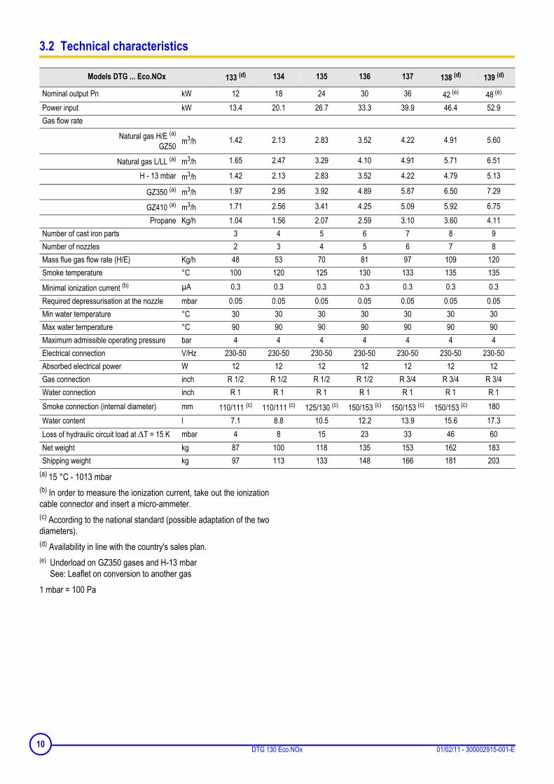
(a) 15 °C - 1013 mbar(b) In order to measure the ionization current, take out the ionizationcable connector and insert a micro-ammeter.(c) According to the national standard (possible adaptation of the twodiameters).(d) Availability in line with the country's sales plan.(e) Underload on GZ350 gases and H-13 mbar
See: Leaflet on conversion to another gas1 mbar = 100 Pa
Models DTG ... Eco.NOx 133 (d) 134 135 136 137 138 (d) 139 (d)
Nominal output Pn kW 12 18 24 30 36 42 (e) 48 (e)
Power input kW 13.4 20.1 26.7 33.3 39.9 46.4 52.9Gas flow rate
Natural gas H/E (a)
GZ50 m3/h 1.42 2.13 2.83 3.52 4.22 4.91 5.60
Natural gas L/LL (a) m3/h 1.65 2.47 3.29 4.10 4.91 5.71 6.51
H - 13 mbar m3/h 1.42 2.13 2.83 3.52 4.22 4.79 5.13
GZ350 (a) m3/h 1.97 2.95 3.92 4.89 5.87 6.50 7.29
GZ410 (a) m3/h 1.71 2.56 3.41 4.25 5.09 5.92 6.75Propane Kg/h 1.04 1.56 2.07 2.59 3.10 3.60 4.11
Number of cast iron parts 3 4 5 6 7 8 9Number of nozzles 2 3 4 5 6 7 8Mass flue gas flow rate (H/E) Kg/h 48 53 70 81 97 109 120Smoke temperature °C 100 120 125 130 133 135 135
Minimal ionization current (b) µA 0.3 0.3 0.3 0.3 0.3 0.3 0.3Required depressurisation at the nozzle mbar 0.05 0.05 0.05 0.05 0.05 0.05 0.05Min water temperature °C 30 30 30 30 30 30 30Max water temperature °C 90 90 90 90 90 90 90Maximum admissible operating pressure bar 4 4 4 4 4 4 4Electrical connection V/Hz 230-50 230-50 230-50 230-50 230-50 230-50 230-50Absorbed electrical power W 12 12 12 12 12 12 12Gas connection inch R 1/2 R 1/2 R 1/2 R 1/2 R 3/4 R 3/4 R 3/4Water connection inch R 1 R 1 R 1 R 1 R 1 R 1 R 1Smoke connection (internal diameter) mm 110/111 (c) 110/111 (c) 125/130 (c) 150/153 (c) 150/153 (c) 150/153 (c) 180Water content l 7.1 8.8 10.5 12.2 13.9 15.6 17.3Loss of hydraulic circuit load at ∆T = 15 K mbar 4 8 15 23 33 46 60Net weight kg 87 100 118 135 153 162 183Shipping weight kg 97 113 133 148 166 181 203
10 DTG 130 Eco.NOx 01/02/11 - 300002915-001-E

3.3 Main parts
1. Safety box:Mounted on the gas block to ensure and check ignitionsequences, plus burner operation and extinguishing sequences.
2. Gas regulation block:It has a progressive opening, regulation valve and safety valve inseries which is controlled by the boiler adjustment dial.
3. Gas inlet
4. Burner
5. Flame inspection window
6. Ignition electrode:This ensures ignition burner ignition using a high voltage spark.
7. Ionization probe:This detects the presence of a burner ignition flame throughionization.
8. Ignition burner
9. Ignition burner gas supply pipe
10. Downdraught thermostat (located on the rear wall of the anti-blowback device)In the event of smoke release, the burner is cut and the boilergoes into standby for 15 minutes. It must not be switched off ormoved at any time.The boiler restarts normally after thisthermostat has cooled and the 15 minutes has finished (indicatedby an alarm indicator flashing on the control panel).
11. Sensor tube
95
10
8518N002
4
12 3
6 78
11
1101/02/11 - 300002915-001-E DTG 130 Eco.NOx

3.4 Operating principle
577 DBC safety box
Operating principleThe ignition and burner surveillance sequences are ensured by thesafety box.
Normal operating cycle
If heating is required, the boiler thermostat TCH closes the contact.The ignition transformer TA integrated into the safety control box andthe ignition burner valve VBA (supply to the ignition burner) areswitched on.Gas from the ignition burner is ignited by the ignition electrode andwithin the time interval ts; a minimum current of 0.3 µA appears onthe ionization sensor SF and the gas valve regulation flap (supplyingthe principal burner) opens.
Operating cycle on safety (start up without flame signal)
If a flame is not detected before the safety time ts, the box makes 2more ignition attempts. If, at the end of the last attempt, there is stillno flame signal, the box goes into safety and the safety indicatorcomes on. To restart the heater, press the reset button on the safetybox.If there is a loss of flame in normal operation, the box automaticallyrepeats the start up sequence.
ResettingThe box is reset after going into safety by pressing the reset button.If the reset button does not work, wait at least 15 seconds beforetrying a second time.
The box may be on safety on its first start up. Press the resettingbutton of the burner.
If the reset button is pressed in normal operation, the gas valvesclose and the box starts a new ignition sequence.
A B
ts
TCH
VA
TA
SF
VBP
TAF
VBA
8518
N00
1
A A1 C1C E
ts
TCH
VA
TA
SF
VBA
VBP
8518
N04
4
A2 C2
TAF
ts ts
12 DTG 130 Eco.NOx 01/02/11 - 300002915-001-E

Operating cycle with the downdraught thermostat cut off
In the event of smoke release by the anti-blowback device, the anti-release safety device switches off the burner with the safety box onstandby for 15 minutes (this is indicated by an alarm indicatorflashing). The 15 minute timed period can only be interrupted by asector cut.To restart the boiler:Wait for around 5 minutes (thermostat cooling time) and press thereset button on the safety control box. If interruptions of this kindhappen repeatedly, contact your fitter.
LegendA Start of operationA1 Second ignition attemptA2 Third ignition attemptB Formation of flame in ignition burnerC End of first ignition attemptC1 End of second ignition attemptC2 On safety through absence of flame signalD Anti-blowback thermostat cutE ResettingF Restart of the boilerSF Burner flame signalTA Ignition transformerTAF Anti-backflow thermostatTCH Boiler thermostatVA Safety lockout warning lightVBA Ignition burner valveVBP Main burner valvetn Downdraught thermostat cooling time: times varyts Safety time: 55 secondstTAF Waiting time: 15 minutes
Required input signalsBox output signalsContact closed
8518
N04
5
D F
TCH
VA
TA
SF
VBP
TAF
VBA
tTAF
tn
1301/02/11 - 300002915-001-E DTG 130 Eco.NOx

4 Installation
4.1 Regulations governing installation
4.1.1 France
Residential buildingsStatutory terms and conditions of installation and maintenance:The installation and maintenance of the appliance must be carriedout by a qualified professional in compliance with the statutory textsof the codes of conduct in force, particularly:
- Order of 27 April 2009 amending the Order of 2 August 1977Technical and safety rules applicable to combustible gas andliquefied hydrocarbon installations situated inside residentialbuildings and their annexes.
- NF P 45-204 standards Gas installation, (formerly DTU 61-1, gas installations: April 1982,addendum no 1: July 1984).
- Local Sanitary RegulationsFor appliances connected to the electricity network:
- NF C 15-100 standards Low voltage electrical installation - Rules..
Establishments open to the publicStatutory terms and conditions of installation:The installation and maintenance of the appliance must be carriedout in compliance with the statutory texts and rules of the codes ofconduct in force, particularly:
- Safety regulations against fire and panic in establishments opento the public:
a. General regulations
For all appliances:- Articles GZ - Installations operating on combustible gases and
liquefied hydrocarbons.Then, depending on use:
- Articles CH-Heating, ventilation, refrigeration, air conditioning andproduction of steam and domestic hot water.
b. Instructions specific to each type of establishment open to thepublic (hospitals, stores, etc.).
Certificate of complianceIn application of Article 25 of the Order of 27 April 2009 amending theOrder of 2 August 1977 amended and Article 1 of the amended Orderof 05/02/1999, the installer is required to draw up certificates ofconformity approved by the Ministers responsible for constructionand gas safety:- Different forms (forms 1, 2 or 3) for a new gas installation.- Model 4 in particular after replacing a furnace with a new one.
4.1.2 Germany
The installation and maintenance of the appliance must be carriedout by a qualified professional in compliance with the statutory textsof the codes of conduct in force, particularly:- DIN 4705: calculation of chimney dimensions- DIN EN 12828 (June 2003 edition): heating systems in buildings.
Planning of hot water heating installations (up to a maximumoperating temperature of 105°C and a maximum output of 1 MW)
- DIN 4753: drinking and industrial water heating installations- DIN 1988: technical rules on drinking water installations (TRW)- DVGW-TRGI: technical rules on gas installations, including
complementary equipment- Working paper DVGW G 260/I: technical rules on the nature of the
gas
14 DTG 130 Eco.NOx 01/02/11 - 300002915-001-E
4.1.3 Switzerland
The installation and maintenance of the appliance must be carriedout by a qualified professional in compliance with the statutory textsof the codes of conduct in force, particularly:- Directives of the Association des Etablissements Cantonaux
d'Assurance Incendie AEAI- Local and cantonal regulations- Directives of the Société Suisse de l'Industrie des Gaz et des Eaux
SSIGE
- Directives on liquefied gases, part 2
The safety distance between combustible substances and the boilerand gaseous effluents must comply with the requirements of theAEAI standard.
4.1.4 Other countries
Installation and maintenance of the boiler must be carried out by aqualified professional in compliance with prevailing local and nationalregulations.
4.2 Package list
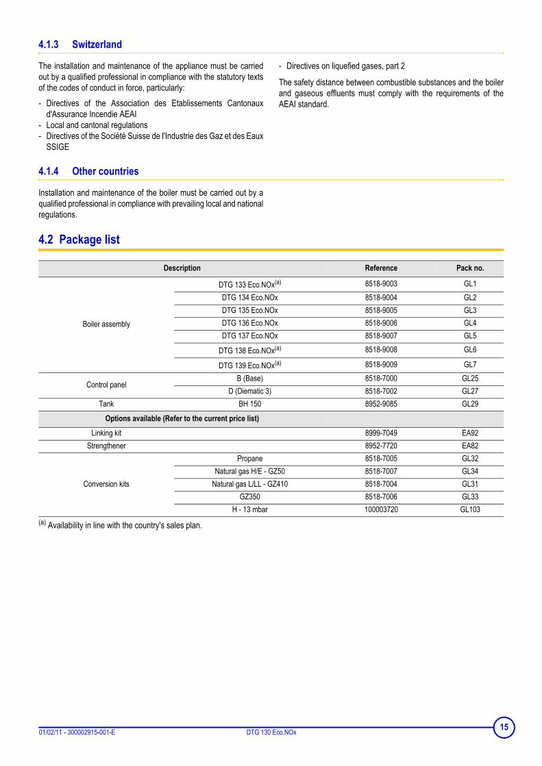
(a) Availability in line with the country's sales plan.
Description Reference Pack no.
Boiler assembly
DTG 133 Eco.NOx(a) 8518-9003 GL1DTG 134 Eco.NOx 8518-9004 GL2DTG 135 Eco.NOx 8518-9005 GL3DTG 136 Eco.NOx 8518-9006 GL4DTG 137 Eco.NOx 8518-9007 GL5
DTG 138 Eco.NOx(a) 8518-9008 GL6
DTG 139 Eco.NOx(a) 8518-9009 GL7
Control panelB (Base) 8518-7000 GL25
D (Diematic 3) 8518-7002 GL27Tank BH 150 8952-9085 GL29
Options available (Refer to the current price list)
Linking kit 8999-7049 EA92Strengthener 8952-7720 EA82
Conversion kits
Propane 8518-7005 GL32Natural gas H/E - GZ50 8518-7007 GL34
Natural gas L/LL - GZ410 8518-7004 GL31GZ350 8518-7006 GL33
H - 13 mbar 100003720 GL103
1501/02/11 - 300002915-001-E DTG 130 Eco.NOx

4.3 Mounting
4.3.1 Position of the boiler
Installations possible:- in the kitchen- in the cellar- in the boiler house
Clearance to allow for:- 5 cm on one of the boiler sides (B)- 70 cm minimum in front- 5 at the rear (A)
Also have the required space for installing the expansion reservoirand the heating circulator.
4.3.2 Ventilation
Do not obstruct the air inlets in the room (even partially).
France: the cross section of the aeration vent, which is compulsoryin the boiler room in which the boiler is installed, must comply with theDTU 61.1 (P 45 204) standard and, in particular, with the instructionon boiler room layout (Book 1764 April 1982).Germany: the cross section of the ventiliation vents, which arecompulsory in the room in which the boiler is installed, must complywith the VDI 2050 form 1 standard and with other prevailingregulations.Other countries: the cross section of the aeration inlet, which iscompulsory in the premises in which the boiler is installed, mustcomply with the standards in force in the country.
Caution:
In order to avoid damage to the boiler, it is necessary to prevent thecontamination of combustion air by chlorine and/or fluoridecompounds, which are particularly corrosive. These compounds arepresent, for example, in aerosol sprays, paints, solvents, cleaningproducts, washing products, detergents, glues, snow clearing salts,etc. Therefore:
- Do not pull in air evacuated from premises using such products:hairdressing salons, dry cleaners, industrial premises (solvents),premises containing refrigeration systems (risk of refrigerantleakage), etc.
- Do not stock such products close to the boilers.
If the boiler and/or peripheral equipment are corroded by suchchloride or fluoride compounds, the contractual guaranteecannot be applied.
A
B
16 DTG 130 Eco.NOx 01/02/11 - 300002915-001-E

4.3.3 Main dimensions
DTG 130 Eco.NOx
DTG 1300 Eco.NOx/B 150 - Right
DTG 1300 Eco.NOx/B 150 - Left
1
4
2
3
850
AF
C
G
601 = =
E
H
D
ØB
583
413
100
39
15
30345
194
373
(1)
5
1
2
3
850
L F846
E413
5
9
ØB
450580
2 9
850
L F846
= =
E
ØB
413
5
1701/02/11 - 300002915-001-E DTG 130 Eco.NOx

DTG 1300 Eco.NOx/H 150
1. Heating flowR1 (1") for one single boilerG1 (1") for boiler with DHW tank
2. Heating returnR1 (1") for one single boilerG1 (1") for boiler with DHW tank
3. Filling and emptying tap(connection for 14 mm interior diameter pipe)
4. Gas inlet ø K
5. Smoke nozzle ø B
6. Hot water outlet - R 3/4 (3/4")
7. Circulation - R 3/4 (3/4")
8. Cold water inlet - R 3/4 (3/4")
9. Drain cock(connection for 14 mm interior diameter pipe)
(a) Availability in line with the country's sales plan.(b) According to the national standard (possible adaptation of the twodiameters)(1) Adjustable feet : basic sizes : 30 mm.Can be adjusted from 30 mm to 42 mm.All height sizes are stated with feet completely screwed in.(2) For hydraulic module mounted to the left or without module(3) For hydraulic module mounted on the right
R = ThreadG = Exterior cylindrical threading, sealed by sheet gasketThe linking kit is not shown on the central view for easier reading.
All instructions and features for the type BH 150 domestic hotwater tank are stated in the instructions supplied with the tank.
270450
580
413 185
30 (1)
monté à gauche ou sans monté à droite
1
4
2
3
9
700
600C
601773
= =
E
H
D
ØB
583
39
34 1195
1044
1578373
5
6
7
8
846
200
(2) (3)
ModelsDTG ... Eco.NOx
DTG ... Eco.NOx/B 150DTG ... Eco.NOx/H 150
133 (a)
1303 (a)1341304
13513051305
13613061306
1371307
1381308
1391309
A 522 522 600 600 744 744 822øB 110 / 111 (b) 110 / 111 (b) 125 / 130 (b) 150 / 153 (b) 150 / 153 (b) 150 / 153 (b) 180C 100 100 93 85 85 85 94D 74 92 98 66 103 67 70E 372 372 450 450 594 594 672F 773 773 773 773 773 773 798G 728 728 728 728 728 728 768H 118 82 85 49 85 49 52
øK (inch) R 1/2 R 1/2 R 1/2 R 1/2 R 3/4 R 3/4 R 3/4L 1122 1122 1200 1200 1344 1344 1422
18 DTG 130 Eco.NOx 01/02/11 - 300002915-001-E

4.3.4 Assembling the appliance
Boiler delivered assembled (without control panel)
Take out the shutter + screen assembly
Slide the panel along the front plate.Push the 1 tubes through the lower opening on the panel case.Ensure that the centring pins 3 fall into the slots 4.
5. Contact spring
6. Bulbs
Place the bulbs in the sensor tube in front of the boiler. Pushthem into the funnel until it butts against it.
2 bulbs (A): Use the contact spring3 bulbs (B): The contact spring is not used
1901/02/11 - 300002915-001-E DTG 130 Eco.NOx

Attach the anti-release safety device onto the 3 connector studson the control panelMake the electrical connections:
See: Control panel instructions.
Thread the connection label into the screen slots. Correctly placethe label using the truncated corner.
4.3.5 Levelling
- Slightly lift the appliance using a lever.- Adjust the 4 feet using a flat-bladed screwdriver.(1) Adjustable feet :Basic dimension 0 mm.Can be adjusted from 0 mm to 12 mm.
20 DTG 130 Eco.NOx 01/02/11 - 300002915-001-E

4.4 Hydraulic connections
4.4.1 Regulations
Installation must be carried out in accordance with the prevailingregulations, the codes of practice and the recommendations in theseinstructions.
Installing the boiler in new installations (installations less than 6 months old)
- Clean the installation with a universal cleaner to eliminate debrisfrom the appliance (copper, flaxen thread, flux).
- Thoroughly flush the installation until the water runs clear andshows no impurities.
Installing the boiler in existing installations- Remove sludge from the installation.- Flush the installation.- Clean the installation with a universal cleaner to eliminate debris
from the appliance (copper, flaxen thread, flux).Thoroughly flush the installation until the water runs clear and showsno impurities.Installation must be carried out in accordance with the prevailingregulations, the codes of practice and the recommendations in theseinstructions.
Important recommendations for connecting the boiler to the heating circuit
Between the boiler and the safety valves there must be nocomplete or partial closing device.France: DTU - 65.11, § 4.22 - NF P 52-203
Heating installations must be designed and implementedto prevent heating circuit water and products contained init returning to the drinking water system (article 16-7Departmental Health Regulations). A CB disconnector(area disconnector for different uncontrollablepressures)must be installed for filling the heating circuitaccording to the NF P 43-011 standard.
Before connecting the heating circuit hydraulic connections, it isessential to rinse the heating circuits to remove any particles whichmight damage certain components (safety valve, pumps, valves...).In the event where the burner is located at the highest point in theinstallation, a dry running or water pressure control device my befitted.
4.4.2 Hydraulic connection of the heating circuit
1. Heating flow
2. Heating return
3. Drain cock (connection for 14 mm interior diameter pipe)
Insulate the heating flow and return pipes only outside thecasing.
The drainage device can be connected with a flexible hose.
4.4.3 Hydraulic connection of the water circuit for domestic use
See: Domestic hot water calorifier instructions.
2101/02/11 - 300002915-001-E DTG 130 Eco.NOx
4.4.4 Filling the system
Boiler self-standing:The installation must be filled via the draining/filling valve. Check thatthe entire installation has been correctly bled.
With domestic hot water tank:See: Domestic hot water calorifier instructions.
4.4.5 Water treatment
Central heating systems must be cleaned to eliminatedebris (copper, strands, brazing flux) linked to theinstallation of the system and deposits that can causemalfunctions (noise in the system, chemical reactionbetween metals). On the other hand, it is important toprotect central heating systems against corrosion, scalingand microbiological growth by using a corrosion inhibitoradapted to all types of systems (steel, cast iron radiators,heated floor, PER)
Switzerland: The water quality must comply with the SICC directivesNo. 97-1F "Treatment of water intended for heating, steam,refrigeration and air conditioning installations".
4.5 Gas connection
It is necessary to abide by the prevailing instructions and regulations.Each time, a blocking tap will be located as near as possible to theheater. A gas filter must be fitted to the boiler inlet.The load loss between the meter and heater must be lower than 1mbar (heater operating).
FrancePipe diameters must be defined in accordance with ATG's(Association Technique de Gaz) B171 specifications.
Other countriesThe diameters of the pipes must be defined in accordance with thestandards in force in your country.
22 DTG 130 Eco.NOx 01/02/11 - 300002915-001-E

4.6 Connection to a chimney
Good
PoorA 40 mm (minimum)The appliance must be installed in accordance with the Codes ofPractice using a leak proof pipe made of a material capable ofwithstanding hot combustion gases and any acidic condensation.The pipe must be laid out to allow any likely condensation to drain.It must be in accordance with existing regulations for pipes used forthis purpose. Standard meshed connection pipes are to be avoided.The pipe connecting the outlet conduit must also be as short aspossible and without a reduced diameter.The vertical section of the draught diverter outlet must be a minimumlength 3x the diameter of the nozzle before an elbow joint is fitted.The pipe must have a diameter not less than the heater's nozzlediameter along its whole length. This pipe must be able to be easilydisassembled and must not have a sudden change in diameter. The outlet conduit must be maintained in a good condition, checkedand cleaned at least once a year.
4.7 Electrical connections
Only qualified professionnals may carry out electricalconnections, always with the power off.
Do not modify the connections inside the control panel.
Make the electrical connections of the appliance according to:- The instructions of the prevailing standards,- The instructions on the circuit diagrams provided with the
appliance,- The recommendations in the instructions.
Standards to be respectedFrance: Electrical connections must be in compliance with the NF C15.100 standard.Other countries: The electrical connections shall comply withstandards in force.
Rules to be respected- Power the appliance via a circuit which includes a remote
omnipolar switch with a gap of more than 3 mm.- Connect all of the cables to the terminal blocks in the control panel.
Keep to the polarity shown on the terminals: phase (L),neutral (N) and earth .
The available output per outlet is 450 W (2 A, with cos ϕ =0.7) and the inrush current must be lower than 16 A.If the charge exceeds one of these values, relay thecommand using a contactor (fitted outside the controlpanel).
Separate the sensor cables from the 230 V cables.Outside the boiler : Use 2 pipes or cable guides at least10 cm apart.
For the 230 V electrical connections, use 3-wire cables with a cross-section of 0.75 mm². For other electrical connections, use the 3 wirecable with a diameter of 0.75 mm².Make the electrical connections:
Control panel instructions.
Options brochure.
4.8 Skeleton Diagrams
Control panel instructions
2301/02/11 - 300002915-001-E DTG 130 Eco.NOx
5 Commissioning
Initial commissioning must be done by a qualifiedprofessional.
5.1 Control panel
Control panel instructions
5.2 Check points before commissioning
Hydraulic circuit- Check that the installation and boiler are adequately filled with
water and correctly irrigated and bled.- Check that there are no leaks on the hydraulic connections.
Gas circuit- Check that the appliance is properly set for the type of gas used. If
this is not the case:5.4 Gas settings (Page: 25)
- Check the supply pressure.- Check the pressure at the nozzles.
5.4.6 Pressure setting and marking of calibrated injectors(page: 27)
5.3 Commissioning procedure
Initial commissioning must be done by a qualifiedprofessional.
1. Check the water pressure in the installation. Top up with morewater if necessary.
2. Open the gas valve.
3. Check that the safety thermostat has not triggered. Remove thesafety thermostat hood and press the reset button with ascrewdriver.
4. Set the On/Off switch to .
5. Make the settings on the control panel
Control panel instructions
24 DTG 130 Eco.NOx 01/02/11 - 300002915-001-E
5.4 Gas settings
DTG 130 Eco.NOx boilers are delivered preset for operation onnatural gases of H/E groups.For operation on another group of gases, carry out the followingoperations.
These actions must be carried out by a qualifiedtechnician.
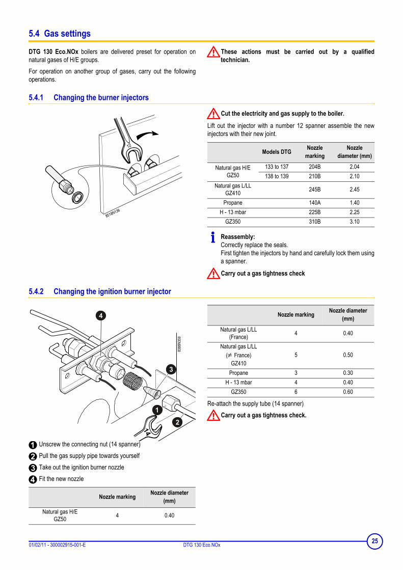
5.4.1 Changing the burner injectors
Cut the electricity and gas supply to the boiler.
Lift out the injector with a number 12 spanner assemble the newinjectors with their new joint.
Reassembly:Correctly replace the seals.First tighten the injectors by hand and carefully lock them usinga spanner.
Carry out a gas tightness check
5.4.2 Changing the ignition burner injector
Unscrew the connecting nut (14 spanner) Pull the gas supply pipe towards yourself Take out the ignition burner nozzle Fit the new nozzle
Re-attach the supply tube (14 spanner)Carry out a gas tightness check.
Models DTG Nozzle marking
Nozzle diameter (mm)
Natural gas H/EGZ50
133 to 137 204B 2.04138 to 139 210B 2.10
Natural gas L/LLGZ410 245B 2.45
Propane 140A 1.40H - 13 mbar 225B 2.25
GZ350 310B 3.10
Nozzle marking Nozzle diameter (mm)
Natural gas H/EGZ50 4 0.40
Natural gas L/LL(France) 4 0.40
Natural gas L/LL(≠ France)
GZ4105 0.50
Propane 3 0.30H - 13 mbar 4 0.40
GZ350 6 0.60
Nozzle marking Nozzle diameter (mm)
2501/02/11 - 300002915-001-E DTG 130 Eco.NOx

5.4.3 Setting the injector pressure
Turn the boiler on..5.2 Check points before commissioning (page: 24)5.3 Commissioning procedure (page: 24)
The pressure must be set by a qualified professional.
- Connect a manometer to the pressure socket located on themanifold.
- Remove the protective cover on the regulator by unscrewing itusing a screwdriver.
- Set the pressure on the injectors by moving the gas regulator onthe valve:
: Increase the pressure: Reduce the pressure
5.4.4 Setting the start up pressure
E Protective hoodF Ionization probe connectionG Ignition electrode connection
Start up pressure may be set if necessary using a flat screwdriver,after the protection has been removed E.Start up pressure is set in the factory on minimum. If it is necessaryto optimise heater start up, it may be set on another value between0º and 270º.
Gas valve opening diagram
Downstream pressure (mbar)Time (s)
Manifold pressure (mbar)
Natural gas H/EGZ50
DTG 133 to 137DTG 138 to 139
1615
Natural gas L/LL 12.1GZ410 12.5
Propane 29
H - 13 mbar 8.4 to 10.2depending on the model
GZ350 6 to 7depending on the model
26 DTG 130 Eco.NOx 01/02/11 - 300002915-001-E
5.4.5 Attaching the label
Affix the label which indicates for which type of gas the boiler is fittedand set.
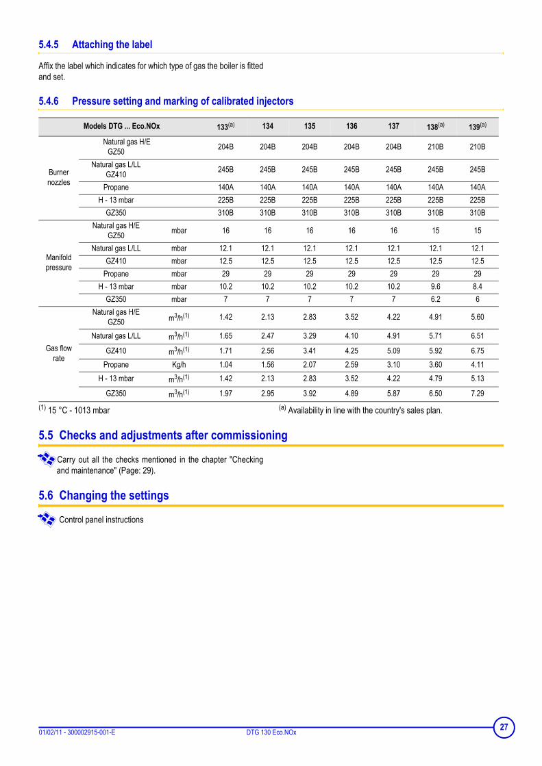
5.4.6 Pressure setting and marking of calibrated injectors
(1) 15 °C - 1013 mbar (a) Availability in line with the country's sales plan.
5.5 Checks and adjustments after commissioning
Carry out all the checks mentioned in the chapter "Checkingand maintenance" (Page: 29).
5.6 Changing the settings
Control panel instructions
Models DTG ... Eco.NOx 133(a) 134 135 136 137 138(a) 139(a)
Burner nozzles
Natural gas H/EGZ50 204B 204B 204B 204B 204B 210B 210B
Natural gas L/LLGZ410 245B 245B 245B 245B 245B 245B 245B
Propane 140A 140A 140A 140A 140A 140A 140AH - 13 mbar 225B 225B 225B 225B 225B 225B 225B
GZ350 310B 310B 310B 310B 310B 310B 310B
Manifold pressure
Natural gas H/EGZ50 mbar 16 16 16 16 16 15 15
Natural gas L/LL mbar 12.1 12.1 12.1 12.1 12.1 12.1 12.1GZ410 mbar 12.5 12.5 12.5 12.5 12.5 12.5 12.5
Propane mbar 29 29 29 29 29 29 29H - 13 mbar mbar 10.2 10.2 10.2 10.2 10.2 9.6 8.4
GZ350 mbar 7 7 7 7 7 6.2 6
Gas flow rate
Natural gas H/EGZ50 m3/h(1) 1.42 2.13 2.83 3.52 4.22 4.91 5.60
Natural gas L/LL m3/h(1) 1.65 2.47 3.29 4.10 4.91 5.71 6.51
GZ410 m3/h(1) 1.71 2.56 3.41 4.25 5.09 5.92 6.75Propane Kg/h 1.04 1.56 2.07 2.59 3.10 3.60 4.11
H - 13 mbar m3/h(1) 1.42 2.13 2.83 3.52 4.22 4.79 5.13
GZ350 m3/h(1) 1.97 2.95 3.92 4.89 5.87 6.50 7.29
2701/02/11 - 300002915-001-E DTG 130 Eco.NOx

6 Switching off the boiler
Set the On/Off switch to 0.On the Off position , the domestic hot water calorifierfitted with a titanium anode is not protected againstcorrosion.
6.1 Precautions to take if there is a danger of frost
Heating circuit:Use a correctly dosed antifreeze to prevent the heating waterfreezing. If this cannot be done, drain the system completely. In allcases, consult the fitter.
Domestic hot water circuit:Drain the domestic water tank and pipes.
6.2 Precautions to take in the event of prolonged shutdown (one year or more)
- Close the gas valve- The boiler and the chimney must be swept carefully. Close the door of the boiler to prevent the internal circulation of air.
28 DTG 130 Eco.NOx 01/02/11 - 300002915-001-E
7 Checking and maintenance
7.1 Checks
Make the following checks at least 1 time a year:- Water level- Safety devices- Checking the ignition burner- Checking pressure to the nozzle- Checking burner safety- Checking the safety thermostat- Checking the downdraught thermostat
7.1.1 Water level
Regularly check the level of water in the installation. Top it up, if needbe, avoiding the abrupt input of cold water into the hot boiler. If thisoperation is repeated several times per season, locate the leak andrepair it.
Do not drain the installation, except in cases of absolutenecessity. For example: Several months' absence with the riskof ice in the building.
7.1.2 Safety devices
Check the safety devices (particularly the valve or safety unit),referring to the instructions provided with these components.
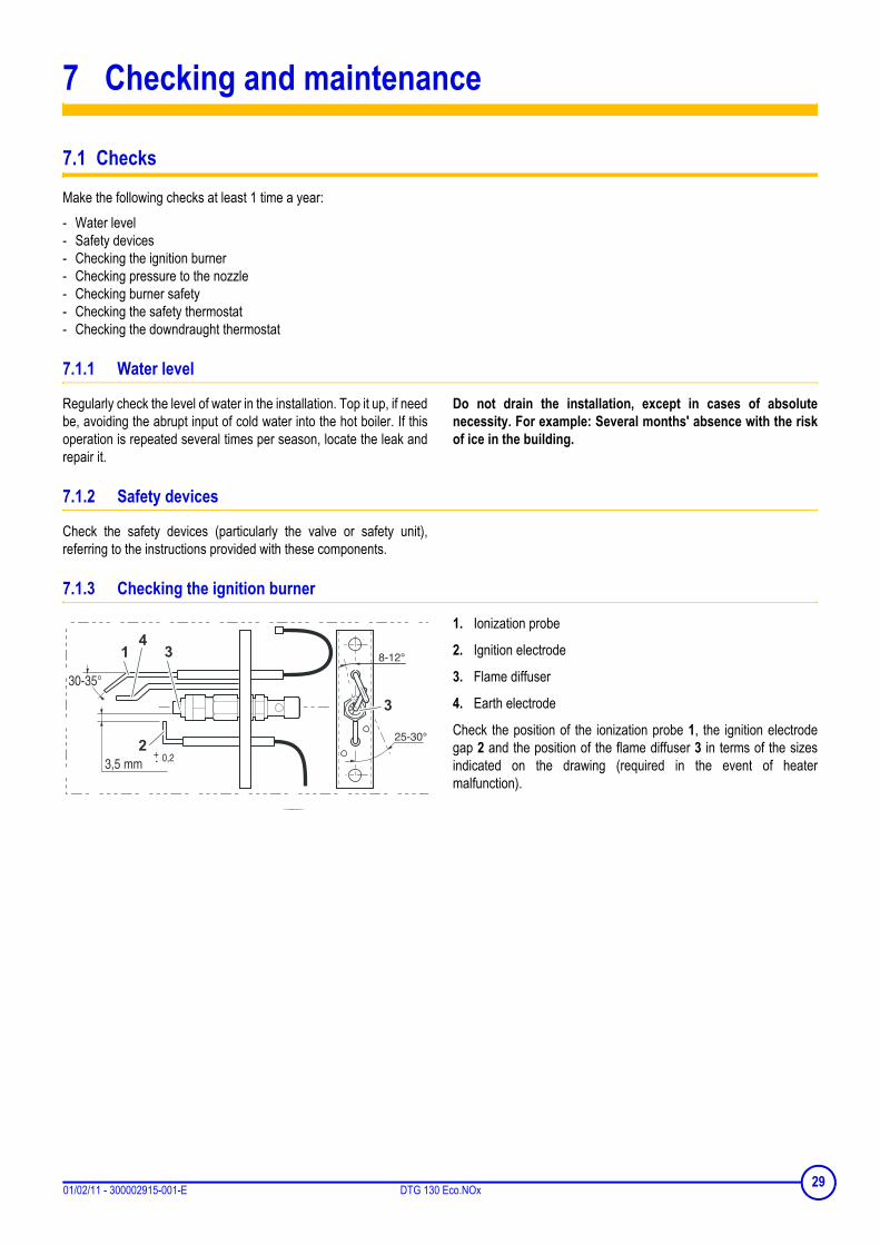
7.1.3 Checking the ignition burner
1. Ionization probe
2. Ignition electrode
3. Flame diffuser
4. Earth electrode
Check the position of the ionization probe 1, the ignition electrodegap 2 and the position of the flame diffuser 3 in terms of the sizesindicated on the drawing (required in the event of heatermalfunction).
2901/02/11 - 300002915-001-E DTG 130 Eco.NOx

7.1.4 Checking pressure to the nozzle
- Unscrew the screw inside the nozzle pressure socket a few turns.- Connect a manometer to the pressure outlet. Check that the
pressure is correct.
- Tighten the pressure socket screw.
Carry out a gas tightness check.
7.1.5 Checking burner safety
Close the gas valve. Check the reaction of the safety system. (Safety box on safetybecause of ionization fault).
7.1.6 Checking the safety thermostat
Place the Summer/Winter switch on to cut the heatingaccelerator to prevent the temperature rising in the installation.Place the 3 position switch " - AUTO - TEST STB" on the TESTSTB position. The burner starts regardless of the setting. Keep theswitch in this position until the safety thermostat cuts (110ºC).
To restart the heater, press the safety thermostat reset button andrepeat the starting operations.
7.1.7 Checking the downdraught thermostat
In the event of smoke release by the anti-blowback device, the anti-release safety device switches off the burner with the safety box onstandby for 15 minutes (this is indicated by an alarm indicatorflashing).Check that the anti-overflow system is working correctly oncommissioning for the first time and during annual servicing of theboiler.
Checking procedureOnly a qualified professional may carry out the check.
Ensure correct ventilation in the premises during the check.
- Turn of the heater and take out the smoke duct linking the heaterto the chimney. Block the boiler flue gas nozzle using a metal plate(or other heat-resistant material).
- On start up, combustion products are evacuated to the back of theheater by the anti-blowback device opening inside.
- The anti-blowback thermostat triggers for a few seconds, cuts theburner and starts the safety box timer (alarm indicator flashing).
- After checking, re-assemble the smoke duct connecting the heaterto the chimney. Wait for about 5 minutes (thermostat cooling time)the cut and reconnect the current using the Start/Stop switch. Theboiler restarts.
Manifold pressure (mbar)
Natural gas H/EGZ50
DTG 133 to 137DTG 138 to 139
1615
Natural gas L/LL 12.1GZ410 12.5
Propane 29
H - 13 mbar 8.4 to 10.2depending on the model
GZ350 6 to 7depending on the model
30 DTG 130 Eco.NOx 01/02/11 - 300002915-001-E

7.2 Maintenance
Carry out the following maintenance at least 1 time a year:- Cleaning main burner and ignition burner- Cleaning of the heating body- Cleaning painted surfaces
7.2.1 Cleaning main burner and ignition burner
Cut the electricity and gas supply to the boiler.
Main burnerClean the burner trains (slits) using a soft brush, a short-handled brush or a vacuum cleaner.Do not use a metal brush.On reassembly, replace the burner earth wire fixed to theright holding nut on the burner drawer.
Ignition burnerClean the filter and the ignition burner injector.Remove ionization probe 1 and the earth electrode 4 deposits(for example using sand paper).Carry out a gas tightness check.
3101/02/11 - 300002915-001-E DTG 130 Eco.NOx

7.2.2 Cleaning of the heating body
If it is necessary to sweep the boiler, remove the burner drawer toprevent deposits and soot blocking the orifices in the gas trains.With the burner out:- Remove the upper panel from the boiler.- Remove the top insulating material.- Remove the sweeping hatch from the draught diverter.- If necessary, clean the boiler body using the special brush
provided.- Clean the combustion chamber using a vacuum cleaner.
7.2.3 Cleaning painted surfaces
- Use a soapy solution and a sponge only.- Rinse with clean water.- Dry with a soft cloth or a chamois leather.
32 DTG 130 Eco.NOx 01/02/11 - 300002915-001-E

7.3 Troubleshooting
7.3.1 Error messages
Control panel instructions
7.3.2 Incidents and solutions
Symptoms Probable causes Solution
The heater does not start and the safety box is not affected (red alarm indicator off)
The heater thermostat is requiring heatSetting (option) is not requiring heat
Create a demand by moving the heater thermostat or the setting level (option)
The safety thermostat has been triggered after overheating Solve the cause of overheating and reset the safety thermostat
No current Set the On/Off switch to
The burner does not ignite and the safety box is not affected (red alarm indicator off)
On safety because of a lack of gas Purge the gas supply pipe then reset the heater using the panel reset button
Gas valve defective Check the gas valve and replace if necessaryNo spark from the electrode Check the electric cable connection to the safety box and the electrode
No ionization currentCheck the ionization probe and earth wire connectionCheck the position of the ionization probe and the flame diffuser in the ignition burner
The burner ignites and the safety box goes into standby (burner cut and the alarm indicator flashes)
downdraught thermostat cut.
Check for adequate draw on the chimney connection. Reset the safety control box.Check that the downdraught thermostat is in good working order. Reset the safety control box.
Please note the seriousness of unplanned intervention onthe combustion product evacuation checking device:evacuation faults must be solved by improving the draughtin the chimney.In the event of a thermostat fault, it must be replaced by apart stated on our "Spare parts list". Its position must notbe modified, which is defined by the 2 bosses on theholding bracket which are located in the 2 holes on thedraught diverter. The thermostat must not be placed out ofservice.
The burner ignites and the safety box is affected (alarm indicator on)
Inversion of the phase and neutral wires on the heater's control panel.
Connect the phase to terminal 1 and neutral to 2.
The burner ignites but with reduced power
Upstream pressure too weak Check gas supplyDirty filter Clean the filterGas valve unit defective Replace the gas valve unitGas valve defective Check gas valve and replace if necessaryUnsuitable injectors Check injectors
Dirty cast iron body (hearth)
Upstream pressure too high Check gas supplyDirty burner Clean the burnerInsufficient or incorrectly placed air supply Enlarge air supply, smoothen airation holes
Gas valve defective Check gas valve and replace if necessary
Noisy heaterPoor purge Purge correctlyBody has scale Descale the heating circuitUnsuitable injectors (Whistling) Check injectors
3301/02/11 - 300002915-001-E DTG 130 Eco.NOx

Heater too hot or too cold for requirements
3 position switch on position Check the position of the 3 position switch
Wrong setting for the heater thermostat
Set the heater thermostat if the heater has SV-matic setting or an ambient thermostat
Flame returnsInjectors too large
Check pressure injectorsPressure too weak
WhistlingInjectors too smallPressure too high
Symptoms Probable causes Solution
34 DTG 130 Eco.NOx 01/02/11 - 300002915-001-E

8 Spare parts - DTG 130 Eco.NOx
01/02/11 - 300002915-002-CTo order a spare part, give the reference number shown on the list.
8.1 Boiler body + Draught diverter + Insulation
DE DIETRICH THERMIQUE S.A.S. - Spare parts centre4, rue d’Oberbronn - F-67110 REICHSHOFFEN - +33 (0)3 88 80 26 50 - +33 (0)3 88 80 26 98
cpr dedietrichthermique.com

8.2 Gas line + Conversion set
8.2.1 3 sections
8.2.2 4-6 sections
36 DTG 130 Eco.NOx 01/02/11 - 300002915-001-E

8.2.3 7-9 sections
8.3 Casing
8.4 Control panels
Control panel instructions
3701/02/11 - 300002915-001-E DTG 130 Eco.NOx

Ref. Code no. Description
Boiler body
1 85188500 Complete base frame - 3 sections
1 85188501 Complete base frame - 4 sections
1 85188502 Complete base frame - 5 sections
1 85188503 Complete base frame - 6 sections
1 85188504 Complete base frame - 7 sections
1 85188505 Complete base frame - 8 sections
1 85188506 Complete base frame - 9 sections
2 97581059 Adjustable feet
3 83755506 Assembled boiler body - 3 sections
3 83755507 Assembled boiler body - 4 sections
3 83755508 Assembled boiler body - 5 sections
3 83755509 Assembled boiler body - 6 sections
3 83755510 Assembled boiler body - 7 sections
3 83755511 Assembled boiler body - 8 sections
3 83755512 Assembled boiler body - 9 sections
4 85188025 Mounting square
5 95365611 1/2" sensor tube - Length 160 mm
6 83750004 Body lifter
7 97549270 Heating flow pipe - 1" - Length 375 mm
8 97549512 Heating return pipe - 1" - Length 135 mm
9 94902073 Drain cock 1/2"
10 94920297 Elbow 1"
Draught diverter
11 85188514 Draught diverter complete - 3 sections
11 85188515 Draught diverter complete - 4 sections
11 85188516 Draught diverter complete - 5 sections
11 85188517 Draught diverter complete - 6 sections
11 85188518 Draught diverter complete - 7 sections
11 85188519 Draught diverter complete - 8 sections
11 85188520 Draught diverter complete - 9 sections
12 97581501 Flue gas nozzle Ø 110/111
12 300000300 Flue gas nozzle Ø 125/130
12 300000301 Flue gas nozzle Ø 150/153
12 97581497 Flue gas nozzle Ø 180
13 85188053 Inspection hatch - 3 sections
13 85188054 Inspection hatch - 4 sections
13 85188055 Inspection hatch - 5 sections
13 85188056 Inspection hatch - 6 sections
13 85188057 Inspection hatch - 7 sections
13 85188058 Inspection hatch - 8 sections
13 85188059 Inspection hatch - 9 sections
14 200000204 Anti-backflow thermostat
15 83758077 Mounting square
16 95363355 Static thermostat
17 200000095 Electric circuit - Anti-backflow thermostat
18 83665501 Screw bag
Insulating material for body
19 200000510 Complete insulating material for body - 3 sections
19 200000511 Complete insulating material for body - 4 sections
19 200000512 Complete insulating material for body - 5 sections
19 200000513 Complete insulating material for body - 6 sections
19 200000514 Complete insulating material for body - 7 sections
19 200000515 Complete insulating material for body - 8 sections
19 200000186 Complete insulating material for body - 9 sections
20 97550513 Insulation under burner - 3 sections
20 97550514 Insulation under burner - 4 sections
20 97550515 Insulation under burner - 5 sections
20 97550516 Insulation under burner - 6 sections
20 97550517 Insulation under burner - 7 sections
20 97550518 Insulation under burner - 8 sections
20 97550519 Insulation under burner - 9 sections
21 83885655 Insulation back of hearth - 3 sections
21 83885656 Insulation back of hearth - 4 sections
21 83885657 Insulation back of hearth - 5 sections
21 83885658 Insulation back of hearth - 6 sections
21 83885659 Insulation back of hearth - 7 sections
21 83885660 Insulation back of hearth - 8 sections
21 83885661 Insulation back of hearth - 9 sections
22 94285095 Tube of silicon mastic
23 96960227 Brush
Gas line
50 200003131 Complete gas circuit - 3 sections
51 85185507 FURIGAS burner drawer - 3 sections
52 200003132 Complete gas circuit - 4 sections
52 200003133 Complete gas circuit - 5 sections
52 200003134 Complete gas circuit - 6 sections
53 200003135 Complete gas circuit - 7 sections
53 200003136 Complete gas circuit - 8 sections
53 200003137 Complete gas circuit - 9 sections
54 85185508 FURIGAS burner drawer - 4 sections
54- 85185509 FURIGAS burner drawer - 5 sections
54 85185510 FURIGAS burner drawer - 6 sections
55 85185511 FURIGAS burner drawer - 7 sections
55 85185512 FURIGAS burner drawer - 8 sections
Ref. Code no. Description
38 DTG 130 Eco.NOx 01/02/11 - 300002915-001-E

55 85185513 FURIGAS burner drawer - 9 sections
56 83885533 FURIGAS burner + Screws
57 95360220 Pressure socket
58 83754945 Earth cable
59 85188921 Complete ignition burner - 3-7-8-9-10 sections
60 85188922 Complete ignition burner - 4-5-6 sections
61 85185514 Ignition burner gas supply pipe - 3-7-8-9-10 sections
62 85185515 Ignition burner gas supply pipe - 4-5-6 sections
63 85185516 Valve
64 85185517 Elbow flange
65 85185518 Right flange
66 95023314 Gasket
67 85185519 Box + Wiring
68 85184904 Burner cable
69 94952101 N374 1/2" x 1" nut
70 94952081 Schraubenmutter N371 1/2"
71 95013062 Green seal 30x21x2
72 97549898 Gas inlet pipe - 3-4-5-6 sections
73 97549899 Gas inlet pipe - 7-8-9 sections
74 83885635 Burner drawer insulation kit 3 sections
74 83885636 Burner drawer insulation kit 4 sections
74 83885637 Burner drawer insulation kit 5 sections
74 83885638 Burner drawer insulation kit 6 sections
75 83885639 Burner drawer insulation kit 7 sections
75 83885640 Burner drawer insulation kit 8 sections
75 83885641 Burner drawer insulation kit 9 sections
76 83665502 Screws
77 85187007 Conversion set H/E/GZ50
77 85187004 Conversion set L/LL/GZ410
77 85187005 Propane conversion kit
Casing
86 85188507 Casing - 3 sections
86 85188508 Casing - 4 sections
86 85188509 Casing - 5 sections
86 85188510 Casing - 6 sections
86 85188511 Casing - 7 sections
86 85188512 Casing - 8 sections
86 85188513 Casing - 9 sections
87 85188521 Front plate - 3 sections
87 85188522 Front plate - 4 sections
87 85188523 Front plate - 5 sections
87 85188524 Front plate - 6 sections
87 85188525 Front plate - 7 sections
87 85188526 Front plate - 8 sections
Ref. Code no. Description
87 85188527 Front plate - 9 sections
88 97525376 Funnel
89 94820110 Catch
90 94820120 Pin
91 85188528 Complete right hand side panel
92 85188529 Complete left hand side panel
93 200000254 Upper rear panel - 3 sections
93 200000255 Upper rear panel - 4 sections
93 200000256 Upper rear panel - 5 sections
93 200000257 Upper rear panel - 6 sections
93 200000258 Upper rear panel - 7 sections
93 200000259 Upper rear panel - 8 sections
93 200000270 Upper rear panel - 9 sections
94 85188542 Lower back panel - 3 sections
94 85188543 Lower back panel - 4 sections
94 85188544 Lower back panel - 5 sections
94 85188545 Lower back panel - 6 sections
94 85188546 Lower back panel - 7 sections
94 85188547 Lower back panel - 8 sections
94 85188548 Lower back panel - 9 sections
95 85188549 Complete door - 3-4 sections
95 85188550 Complete door - 5-6 sections
95 85188551 Complete door - 7-8 sections
95 85188552 Complete door - 9 sections
96 85188553 Complete top panel - 3-4 sections
96 85188554 Complete top panel - 5-6 sections
96 85188555 Complete top panel - 7-8 sections
96 85188556 Complete top panel - 9 sections
99 85188535 Additional part set
100 97525372 Narrow screen
101 97525373 Wide scren
102 97525374 Narrow shutter
103 97525375 Wide shutter
104 97525370 Narrow body
105 97525371 Wide body
106 200001290 Housing screws packet
Control panels
Control panel instructionsGL25 B control panel
GL27 D control panel
Ref. Code no. Description
3901/02/11 - 300002915-001-E DTG 130 Eco.NOx
© CopyrightAll technical and technological information contained in these technical instructions, as well as anydrawings and technical descriptions supplied, remain our property and shall not be multipliedwithout our prior consent in writing.Subject to alterations.
01/02/11
DE DIETRICH THERMIQUE
57, rue de la Gare F- 67580 MERTZWILLER - BP 30


