MArch 1 Li Yin Kwan, Jess
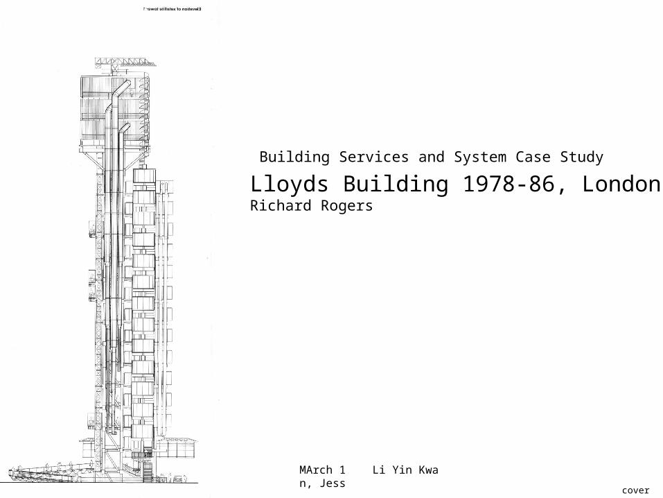
Building Services and System Case Study
Lloyds Building 1978-86, LondonRichard Rogers
cover
General information
Lloyds Building 1978-86, London
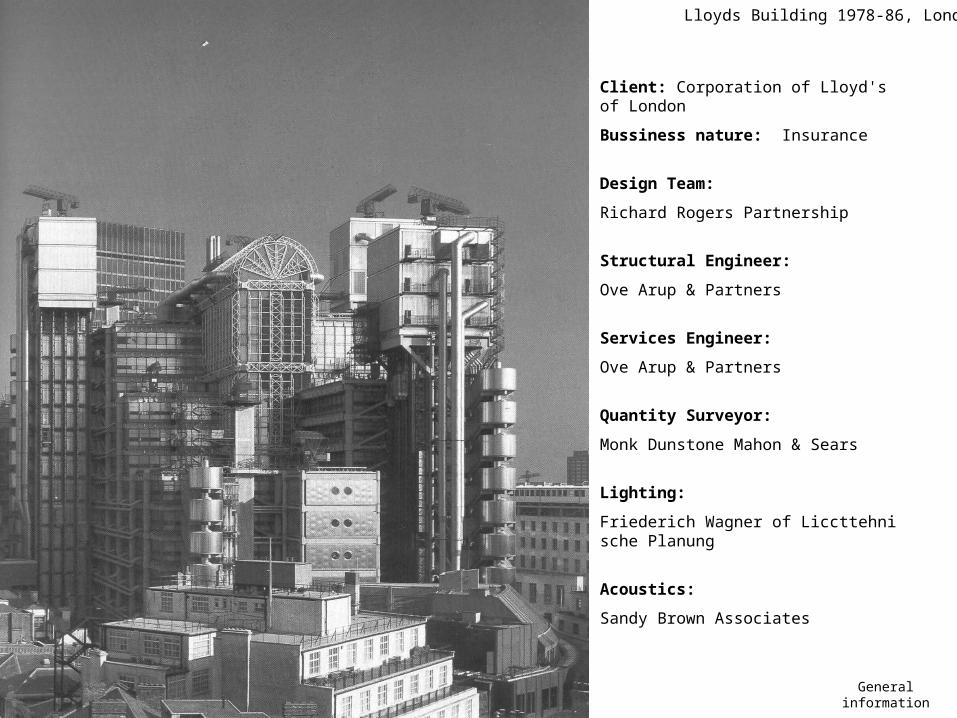
Client: Corporation of Lloyd's of London
Bussiness nature: Insurance
Design Team:
Richard Rogers Partnership
Structural Engineer:
Ove Arup & Partners
Services Engineer:
Ove Arup & Partners
Quantity Surveyor:
Monk Dunstone Mahon & Sears
Lighting:
Friederich Wagner of Liccttehnische Planung
Acoustics:
Sandy Brown Associates
site
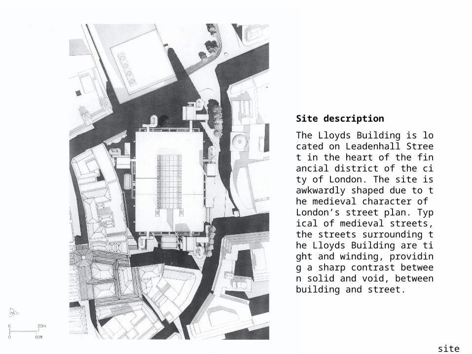
Site description
The Lloyds Building is located on Leadenhall Street in the heart of the financial district of the city of London. The site is awkwardly shaped due to the medieval character of London’s street plan. Typical of medieval streets, the streets surrounding the Lloyds Building are tight and winding, providing a sharp contrast between solid and void, between building and street.
Lloyds Building 1978-86, London
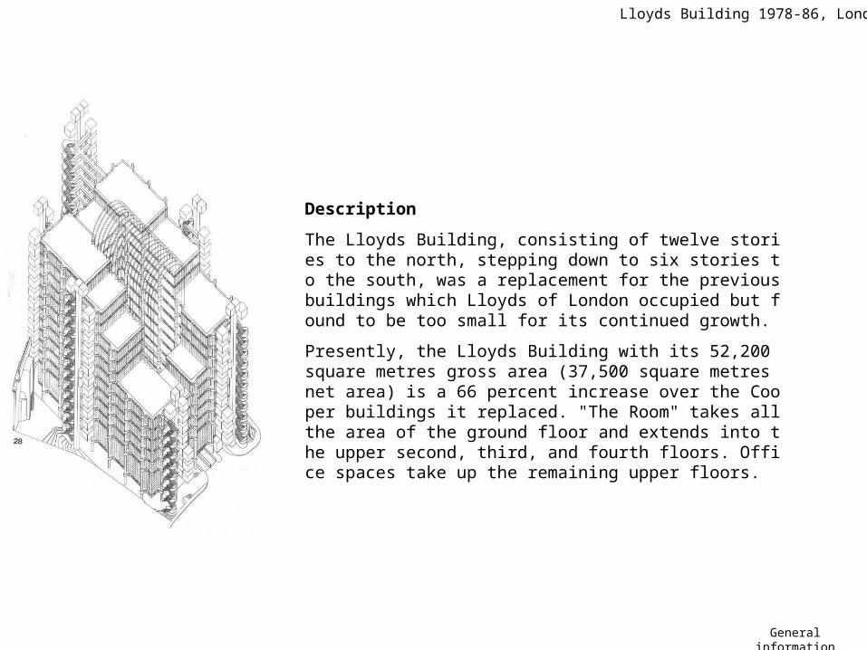
Description
The Lloyds Building, consisting of twelve stories to the north, stepping down to six stories to the south, was a replacement for the previous buildings which Lloyds of London occupied but found to be too small for its continued growth.
Presently, the Lloyds Building with its 52,200 square metres gross area (37,500 square metres net area) is a 66 percent increase over the Cooper buildings it replaced. "The Room" takes all the area of the ground floor and extends into the upper second, third, and fourth floors. Office spaces take up the remaining upper floors.
General information

Requirements
The Room – required large open adaptive space
Dating back to the 17th century, Lloyds of London has today transformed itself into a modern market place operating on the principles of a traditional market. Composed of a society of underwriters, each having their individual stall in the Lloyd's market, the efficiency and success of Lloyd's depends on the interaction between individuals and in the contact gained from working in a large open space, an open market, called "The Room".
Expansion – continue growth leads to need of expansion and flexible structural and services layout
The Corporation of Lloyds of London had already moved several times in attempt to suit its continued growth before acquiring the site on Leadenhall Street in the 1920’s. During the World War II, German bombs flattened the adjacent sites; however, the Cooper building in which Lloyds resided survived. In 1950, Lloyds, foreseeing a further need for expansion bought the surrounding sites and began to build the "new" Lloyds. This new building, completed in 1958, was linked to the 1928 building by a 38-foot bridge spanning over Lime Street.Continued growth of Lloyds quickly led them to reevaluate their situation and again look for ways to expand. By the 1960s and 1970s, the 1958 building was already too small and Lloyds now began to look at 1928 building as a possibility in meeting their expansionist ideals. The 1928 building ultimately became their solution. Although listed (grade II) by the government, it was allowed by the City to be demolished in 1981 in place of the current Lloyds Building, which was completed in 1986.
General information

Climatic Summary
Latitude: 51 09 N
Longitude: 000 11 W
Elevation: 62 m
London has a relatively cool climate year round. Temperatures range from 22 degrees Celsius in the summer to 0 degrees Celsius in the winter. London receives substantial amounts of precipitation throughout the year.
The sky conditions are largely overcast and the wind comes primarily from the southwest with a speed of
approximately 10 knots.
Considerations
-heat loss to outside
-Interior temperature
Climate
Strategy
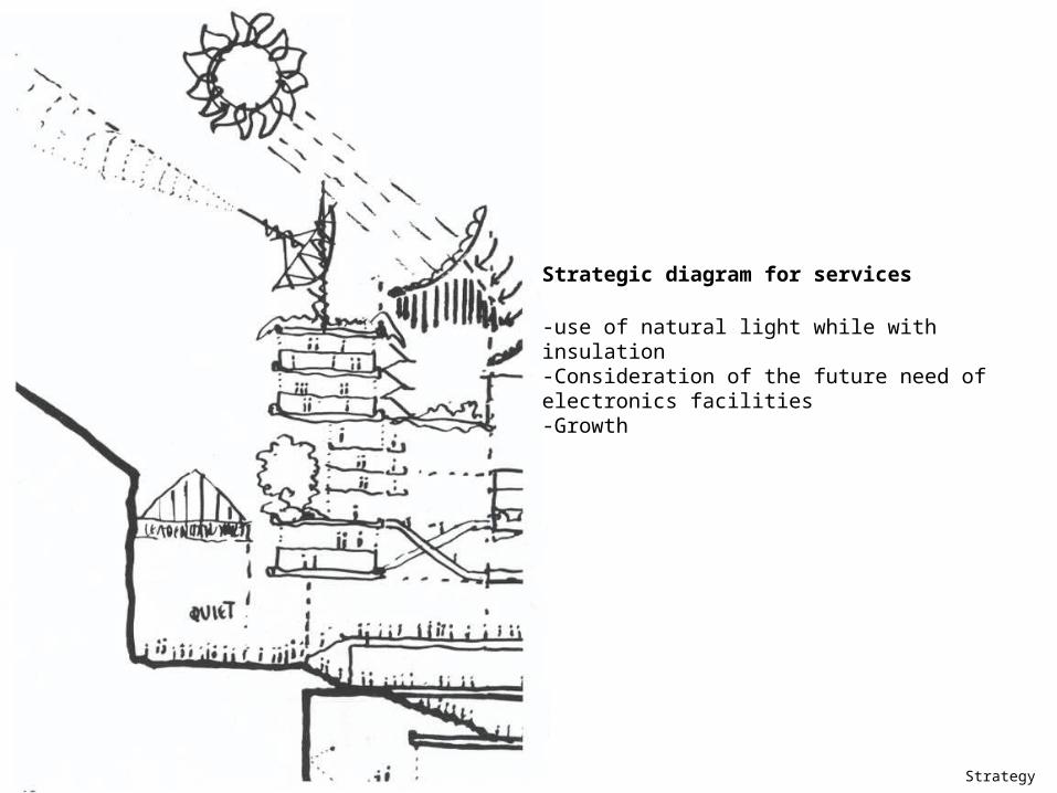
Strategic diagram for services
-use of natural light while with insulation-Consideration of the future need of electronics facilities-Growth
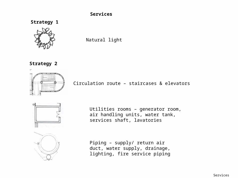
Services
Natural light
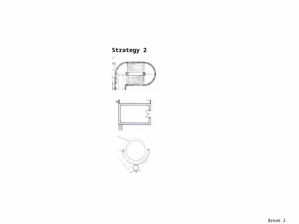
Circulation route – staircases & elevators
Utilities rooms – generator room, air handling units, water tank, services shaft, lavatories
Piping – supply/ return air duct, water supply, drainage, lighting, fire service piping
Services
Strategy 1
Strategy 2
break1
Strategy 1

Strategy 1 – natural lighting
Strategy 1 - Natural lighting
Stepping Form
The Lloyds Building, consisting of twelve stories to the north, stepping down to six stories to the south, sunlight penetration thus utilized.
the incorporation of the atrium
The atrium was a key feature in the reduction of the loads coming from lighting. The atrium increases in volume and surface area as it progresses toward the south.
The office levels increase as the progress northward allowing a large surface area for diffused light coming from the north.
A significant amount of natural lighting reaching down into "The Room" demonstrates the success in the design of the atrium.
Furthermore, every location in the building is located within 7 meters from a natural source of light.
Break 2
Strategy 2
Services data
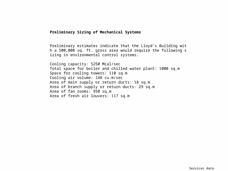
Preliminary Sizing of Mechanical Systems
Preliminary estimates indicate that the Lloyd's Building with a 500,000 sq. ft. gross area would require the following sizing in environmental control systems.
Cooling capacity: 5250 Mcal/secTotal space for boiler and chilled water plant: 1000 sq.mSpace for cooling towers: 110 sq.mCooling air volume: 148 cu.m/secArea of main supply or return ducts: 18 sq.mArea of branch supply or return ducts: 29 sq.mArea of fan rooms: 950 sq.mArea of fresh air louvers: 117 sq.m

Served & servant
Served & servant
Strategy 2 – served & serva
nt
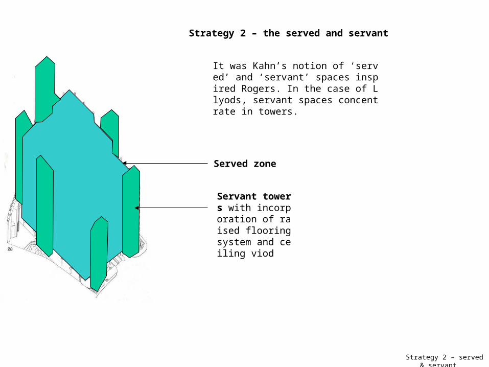
Strategy 2 – the served and servant
It was Kahn’s notion of ‘served’ and ‘servant’ spaces inspired Rogers. In the case of Llyods, servant spaces concentrate in towers.
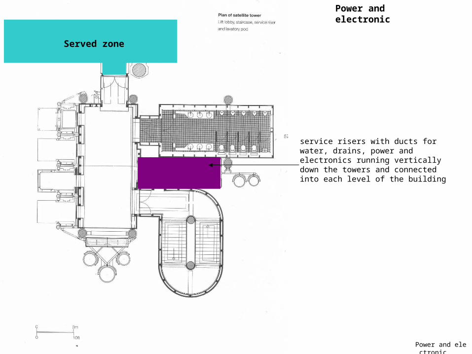
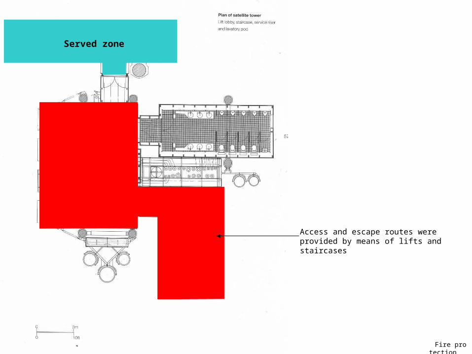
Served zone
Servant towers with incorporation of raised flooring system and ceiling viod

Servant tower –pl
an
Served zone
Servant towers with incorporation of raised flooring system and ceiling void
The services towers, 3 of them principally for fire fighting and escape.
The other 3 for lifts, lavatories and risers, are the visual expression of the Kahnian doctrine of ‘served and servant spaces’

Tower – vertical planning
The towers form a flexible framework for the ventilation plant, lifts, service risers and lavatories (all the 33 lavatory units were manufactured and fitted out) attached to them.
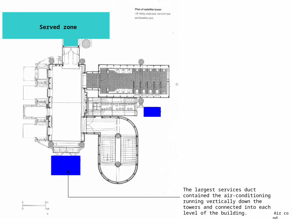
Four towers carry major plant-rooms, with mains services running vertically down the towers and connected into each level of the building.
The largest services duct contained the air-conditioning, with lesser duct for water, drains, power and electronics
The towers carry majors plant rooms on top
Main services running vertically down the towers
Tower – detailed l
ayout
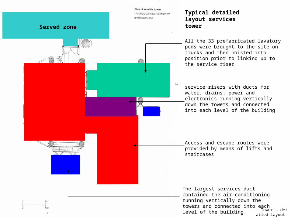
Typical detailed layout services tower
All the 33 prefabricated lavatory pods were brought to the site on trucks and then hoisted into position prior to linking up to the service riser
Access and escape routes were provided by means of lifts and staircases
service risers with ducts for water, drains, power and electronics running vertically down the towers and connected into each level of the building
The largest services duct contained the air-conditioning running vertically down the towers and connected into each level of the building.
Served zone

integration
Integration
Raised fl & ceiling void-
section deatil
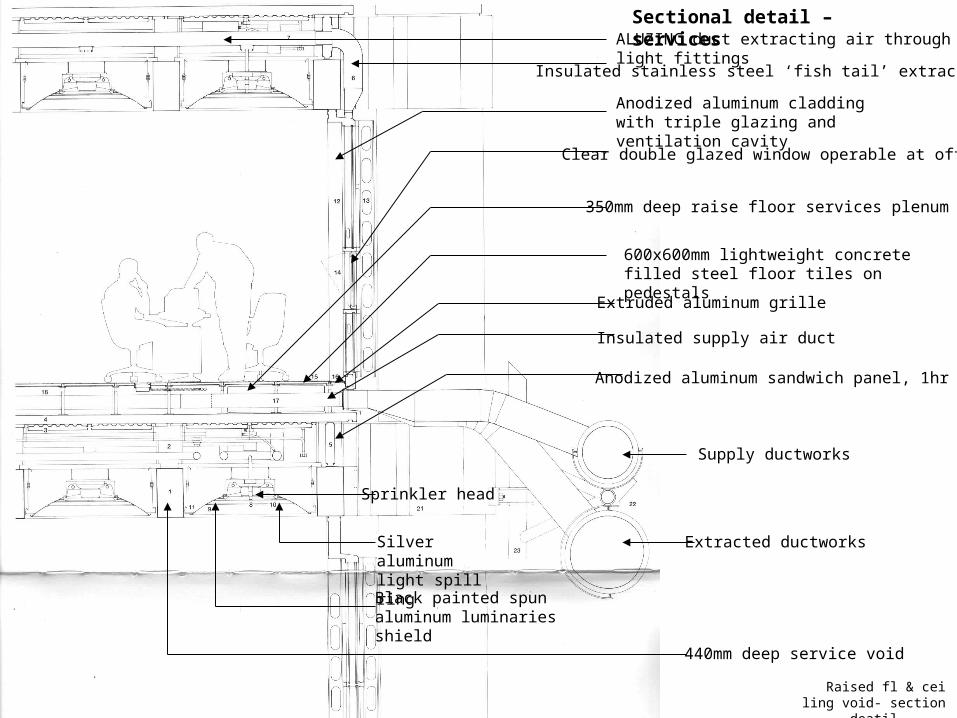
Sectional detail – services ALUZINC duct extracting air through light fittings
Insulated stainless steel ‘fish tail’ extract duct
Anodized aluminum cladding with triple glazing and ventilation cavity
Clear double glazed window operable at office
Extruded aluminum grille
600x600mm lightweight concrete filled steel floor tiles on pedestals
Insulated supply air duct
350mm deep raise floor services plenum
Supply ductworks
Extracted ductworks
Anodized aluminum sandwich panel, 1hr FRP
440mm deep service void
Sprinkler head
Silver aluminum light spill ring
Black painted spun aluminum luminaries shield
Sub-Air conditioning
Air conditioning

Air cond. & heat cycle1
Air conditioning system
Supply ductworks
Conditioned air is distributed through a sub-floor plenum into the offices
stale air is extracted from above through the multi-function luminaries
ALUZINC duct extracting air through light fittings
The extracted air is passed to the perimeter of the building and forced through the triple-layered exterior glazing – ensuring an almost zero heat loss from the offices during the winter and reducing heat gain in summer.
Extracted ductworks
The operable window allows individuals the ability to "acquire" fresh air if the feel it necessary. The placement of the window encourages individuals to work while sitting rather than standing since that is where the views are held. It also allows interior light to be reflected back into the interior during the night and diffuses direct sunlight during the day. The need to take mechanical systems into careful consideration when designing energy conscious builidings is made evident when one compares the the overall space that they consume in a building in relation to the human being
Clear double glazed window operable at office
Air cond.
The largest services duct contained the air-conditioning running vertically down the towers and connected into each level of the building.
Served zone

Air cond. & heat cycle2
The heat cycleHeat from the return air is collected in the basement sprinkler tanks and re-used. The internal concrete soffits and slabs are ‘heat sinks’, absorbing heat during occupation and being cooled off overnight using naturally chilled night air.
This allow cooling to follow a 24-hour cycle and reduces the peak cooling requirement.
Air handling equipment is located at basement level and in four service tower plant-rooms.
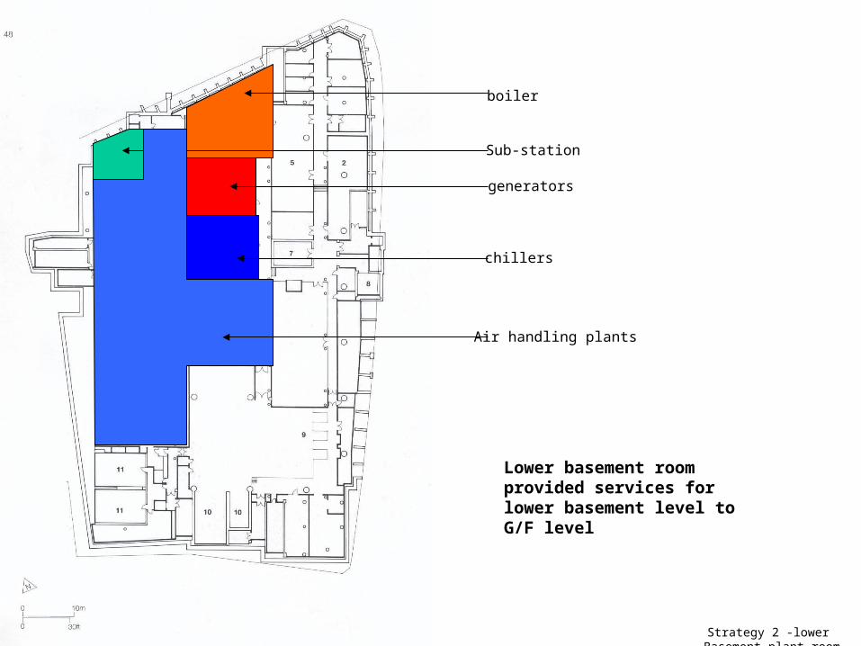
Strategy 2 -lower Basement plant room
Lower basement room provided services for lower basement level to G/F level
boiler
Sub-station
generators
chillers
Air handling plants
Sub-lighting
Lighting
Lighting
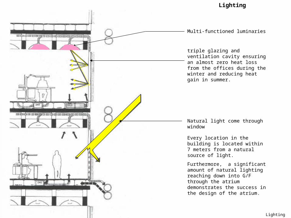
Multi-functioned luminaries
Lighting
Every location in the building is located within 7 meters from a natural source of light.
Furthermore, a significant amount of natural lighting reaching down into G/F through the atrium demonstrates the success in the design of the atrium.
Natural light come through window
triple glazing and ventilation cavity ensuring an almost zero heat loss from the offices during the winter and reducing heat gain in summer.

Sub-power&ele
Power and electronic

Power and electronic
Power and electronic
350mm deep raise floor services plenum housed the power and electronic conduit
Power and electronic
service risers with ducts for water, drains, power and electronics running vertically down the towers and connected into each level of the building
Served zone
Power and electronic

Sub-fire
Fire protection

Fire protection
Anodized aluminum sandwich panel, 1hr FRP
Sprinkler head
Fire protection
Sprinkler system was hold in the ceiling void and sprinkler heads were incorporated into the multi-functioned luminaries
Fire protection
Access and escape routes were provided by means of lifts and staircases
Served zone
Structural system
Structural system
description
Description
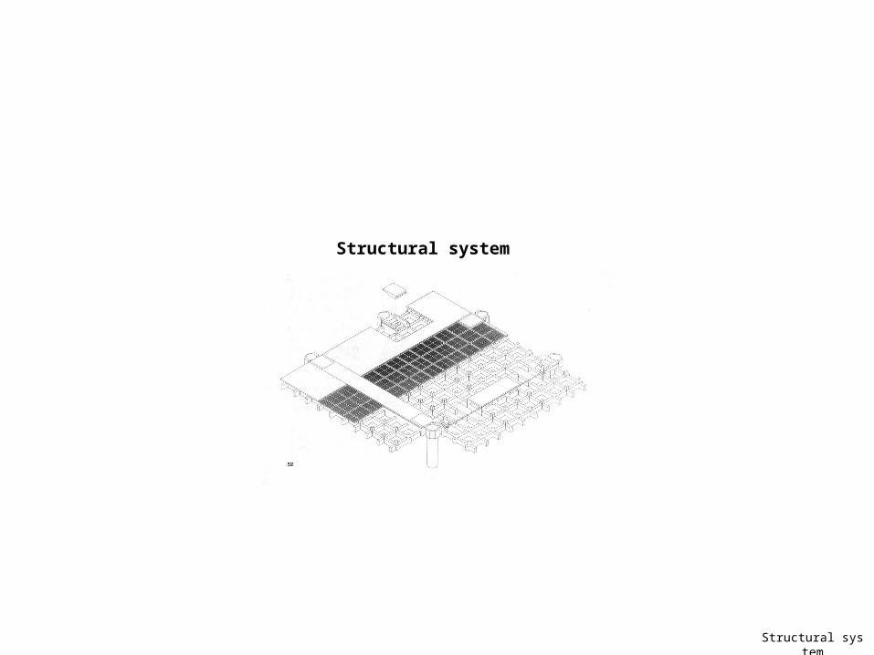
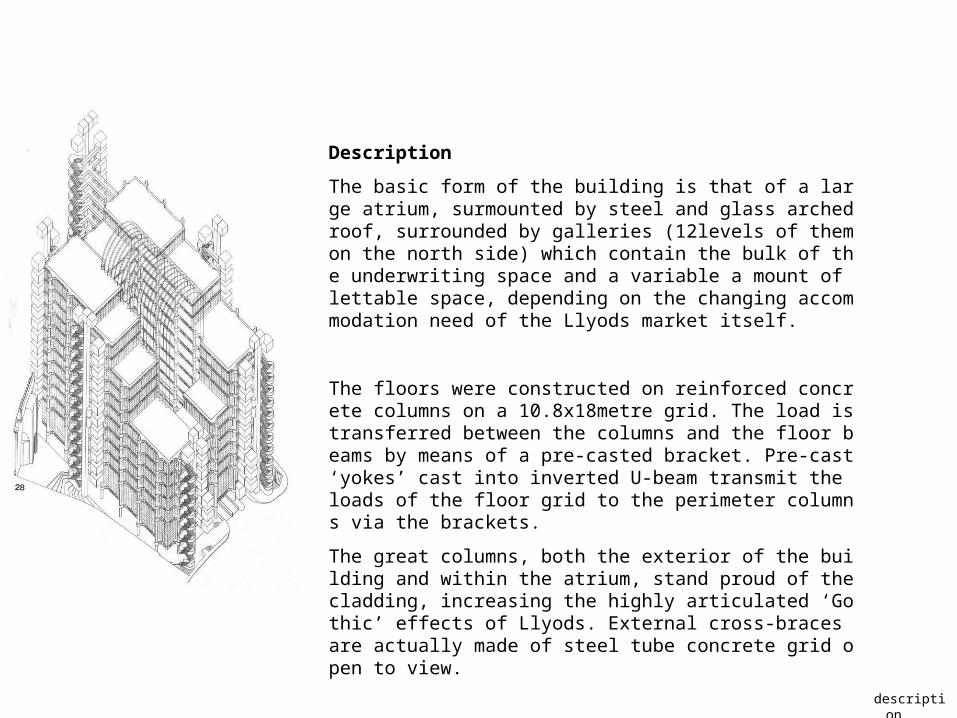
The basic form of the building is that of a large atrium, surmounted by steel and glass arched roof, surrounded by galleries (12levels of them on the north side) which contain the bulk of the underwriting space and a variable a mount of lettable space, depending on the changing accommodation need of the Llyods market itself.
The floors were constructed on reinforced concrete columns on a 10.8x18metre grid. The load is transferred between the columns and the floor beams by means of a pre-casted bracket. Pre-cast ‘yokes’ cast into inverted U-beam transmit the loads of the floor grid to the perimeter columns via the brackets.
The great columns, both the exterior of the building and within the atrium, stand proud of the cladding, increasing the highly articulated ‘Gothic’ effects of Llyods. External cross-braces are actually made of steel tube concrete grid open to view.

Atrium Light steel roof
Design of the atrium roof
A lightweight contrast to the concrete superstructure of the building
floor and column
Columns, Beams and Floors
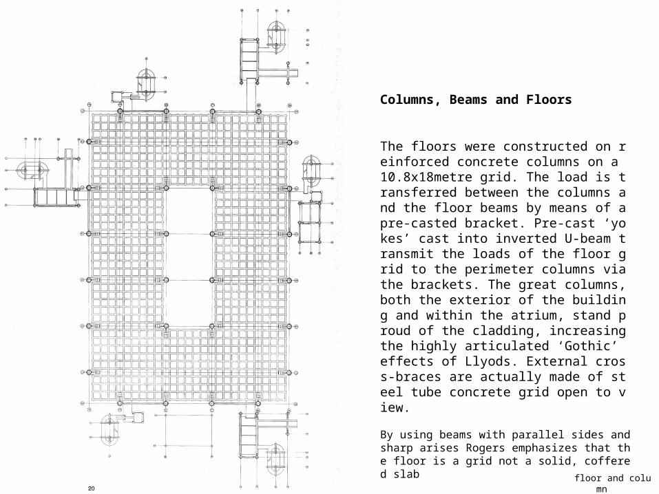
The floors were constructed on reinforced concrete columns on a 10.8x18metre grid. The load is transferred between the columns and the floor beams by means of a pre-casted bracket. Pre-cast ‘yokes’ cast into inverted U-beam transmit the loads of the floor grid to the perimeter columns via the brackets. The great columns, both the exterior of the building and within the atrium, stand proud of the cladding, increasing the highly articulated ‘Gothic’ effects of Llyods. External cross-braces are actually made of steel tube concrete grid open to view.
By using beams with parallel sides and sharp arises Rogers emphasizes that the floor is a grid not a solid, coffered slab

The waffle slab
In situ concrete was latter substituted. U-beams transfer the loads of the floor grid to the columns via a bracket system
Main concrete columns
concrete bracket
‘Yokes’

assemble
Pre-cast concrete bracket and ‘yoke’ assemblies
Pre-cast concrete bracket
yoke

services support
Services supports
Axonometrics of the pre-cast concrete ‘kit of parts’ for the sevices towers
section
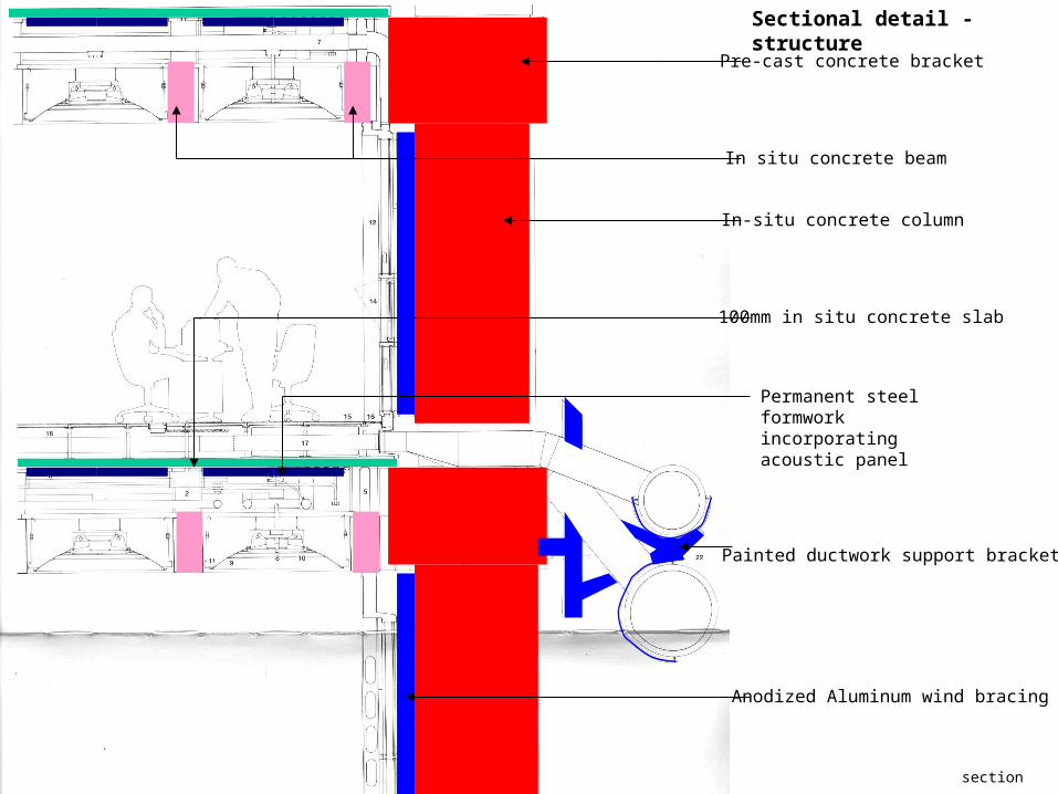
Sectional detail - structure
Pre-cast concrete bracket
In-situ concrete column
Painted ductwork support bracket
In situ concrete beam
Permanent steel formwork incorporating acoustic panel
100mm in situ concrete slab
Anodized Aluminum wind bracing

Photos
Photos

photos- Overall
view
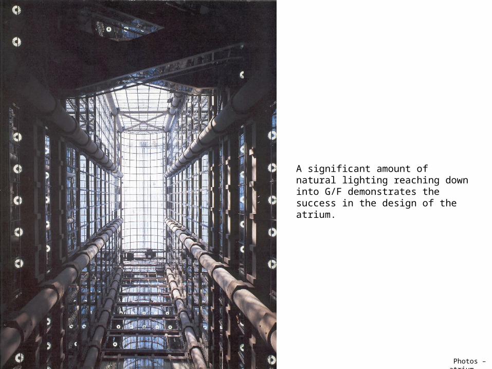
Photos – atrium
A significant amount of natural lighting reaching down into G/F demonstrates the success in the design of the atrium.
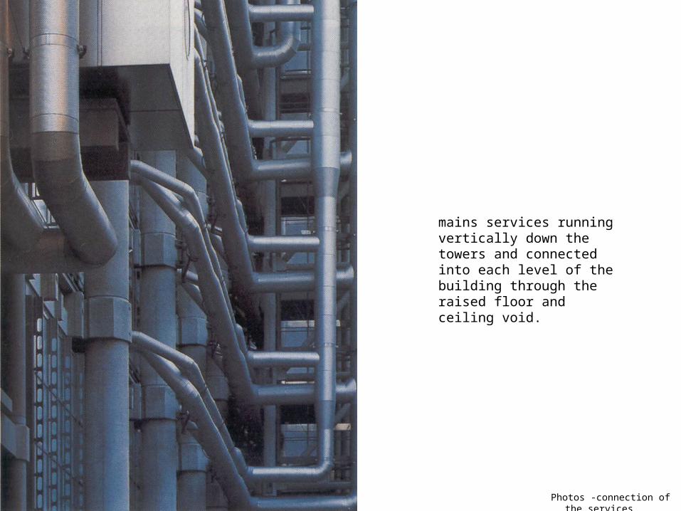
Photos -connection of the service
s
mains services running vertically down the towers and connected into each level of the building through the raised floor and ceiling void.
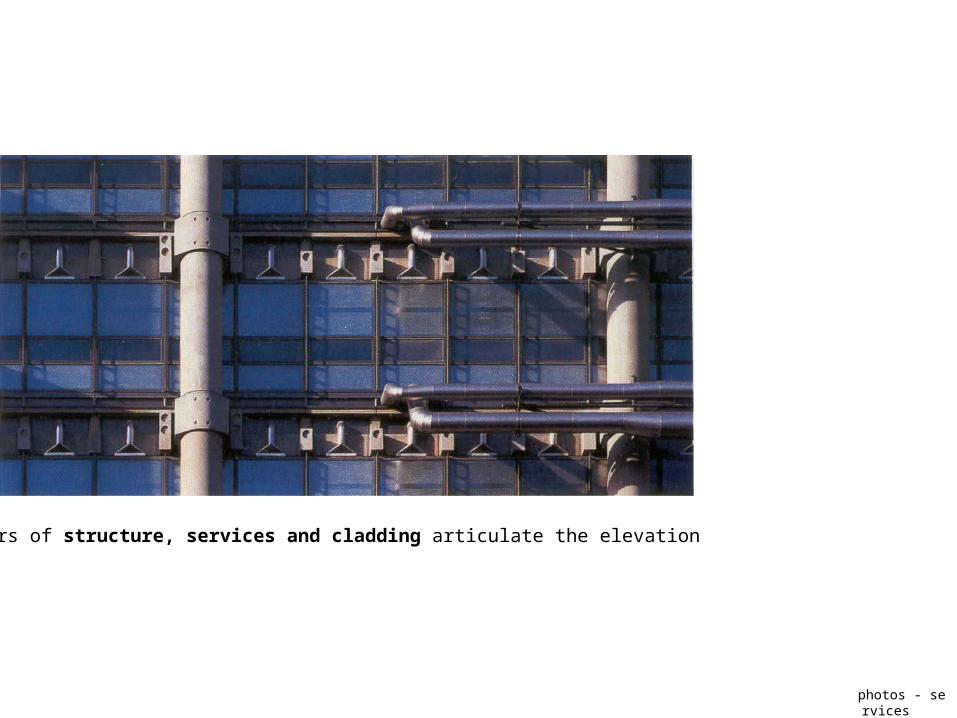
photos - services
The layers of structure, services and cladding articulate the elevation
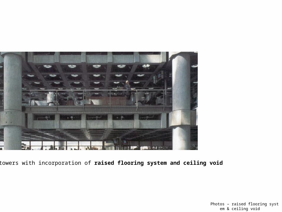
Photos – raised flooring system & ceiling v
oid
Servant towers with incorporation of raised flooring system and ceiling void

photos– in situ concrete column & pre-ca
st concrete bracket
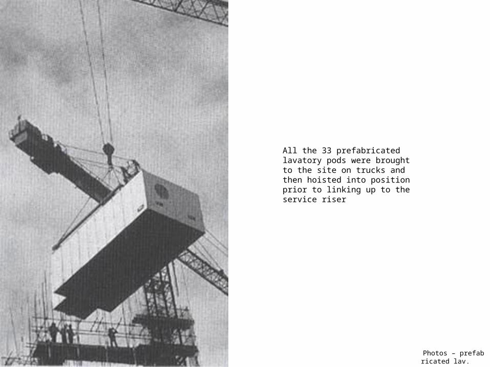
Photos – prefabricated l
av.
All the 33 prefabricated lavatory pods were brought to the site on trucks and then hoisted into position prior to linking up to the service riser
Conclusion
Undoubtedly, the Llyods building demonstrated Richard Rogers and his engineers’ very best skill in handling the appropriate building sevices and structural systems.
It suits very well of the need of growthAnd the future development of IT, thus the need of electronics spaces…….
It is overwhelming
Thanks Mr. Rogers. Llyods taught us a lot.

conclusion
‘ A house is a machine for living in.’ Le Corbusier
However, is that Le Corbusier taught us to design like a machine ?
‘Do not forget architecture.’
Thanks Mr. Rogers. Llyods taught us a lot.


