
MATH CO-PROCESSOR 8087
Rajiv R Bhandari1
2
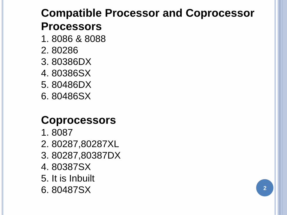
Compatible Processor and Coprocessor
Processors1 8086 amp 8088
2 80286
3 80386DX
4 80386SX
5 80486DX
6 80486SX
Coprocessors1 8087
2 8028780287XL
3 8028780387DX
4 80387SX
5 It is Inbuilt
6 80487SX
INTRODUCTION
8087 was the first math coprocessor for 16-bit
processors designed by Intel
It was built to pair with 8086 and 8088
The purpose of 8087 was to speed up the computations
involving floating point calculations
Addition subtraction multiplication and division of
simple numbers is not the coprocessorrsquos job
It does all the calculations involving floating point
numbers like scientific calculations and algebraic
functions3
INTRODUCTION
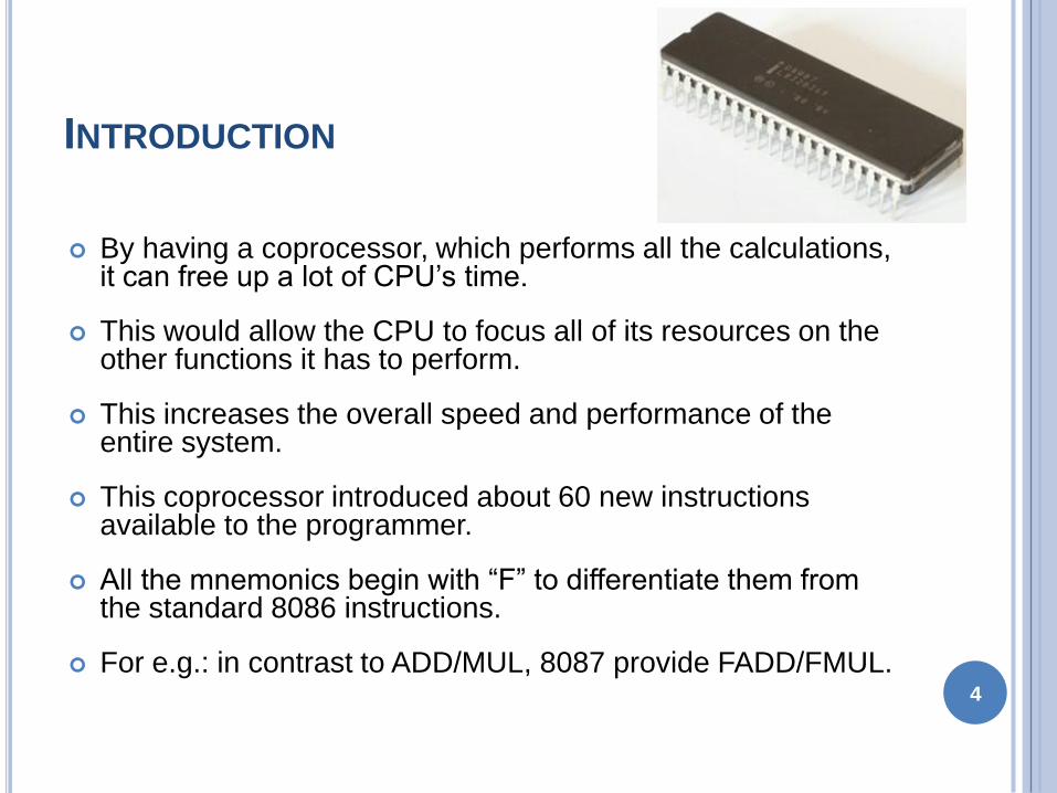
By having a coprocessor which performs all the calculations it can free up a lot of CPUrsquos time
This would allow the CPU to focus all of its resources on the other functions it has to perform
This increases the overall speed and performance of the entire system
This coprocessor introduced about 60 new instructions available to the programmer
All the mnemonics begin with ldquoFrdquo to differentiate them from the standard 8086 instructions
For eg in contrast to ADDMUL 8087 provide FADDFMUL4
INTRODUCTION
Math coprocessor is also called as
Numeric Processor Extension (NPX)
Numeric Data Processor (NDP)
Floating Point Unit (FPU)
5
ARCHITECTURE OF 8087
8087 coprocessor is designed to operate with 8086
microprocessor
The microprocessor and coprocessor can execute
their respective instructions simultaneously
Microprocessor interprets and executes the normal
instruction set and the coprocessor interprets and
executes only the coprocessor instructions
All the coprocessor instructions are ESC
instructions ie they start with ldquoFrdquo
6
ARCHITECTURE OF 8087
7
ARCHITECTURE OF 8087
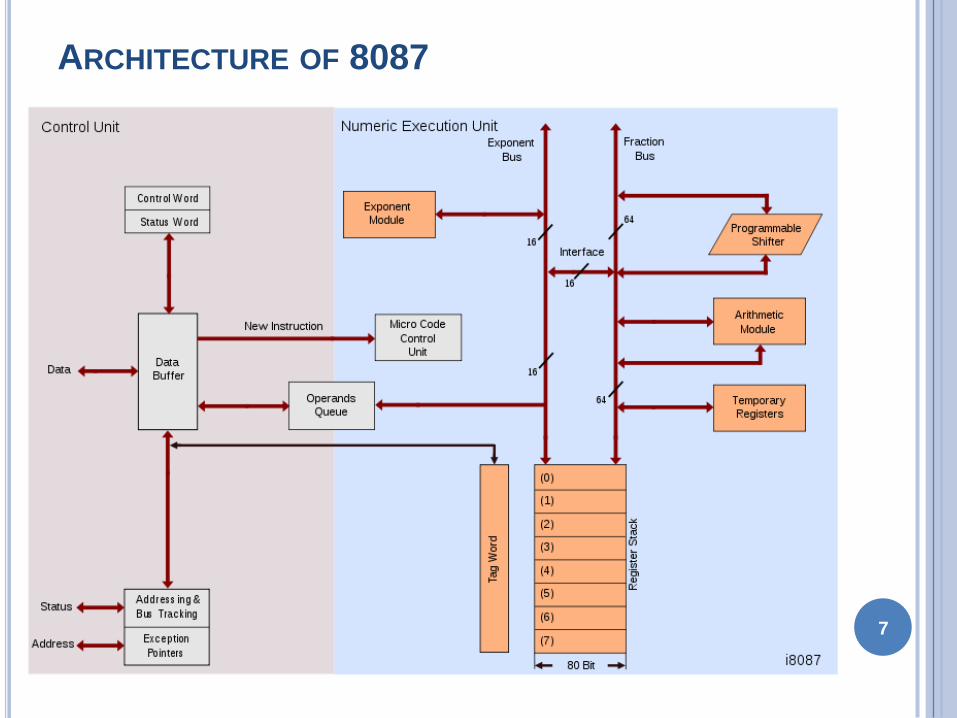
The internal structure of 8087 coprocessor is
divided into two major sections
Control Unit (CU)
Numerical Execution Unit (NEU)
8
CONTROL UNIT (CU)
It interfaces coprocessor to the microprocessor
system bus
It also synchronize the operation of the
coprocessor and the microprocessor
This unit has a Control Word Status Word and
Data Buffer
If an instruction is ESC instruction then
coprocessor executes it
If not then microprocessor executes9
NUMERIC EXECUTION UNIT (NEU)
This unit is responsible for executing all
coprocessor instructions
It has an 8 register stack that holds the operands
for instructions and result of instructions
The stack contains 8 registers that are 80-bits wide
Numeric data is transferred inside the coprocessor
in two parts
64-bit mantissa bus
16-bit exponent bus10
STATUS REGISTER
11
STATUS REGISTER
Status Register tells the overall status of 8087
coprocessor
It is a 16-bit register
It is accessed by executing the FSTSW instruction
This instruction stores the contents of status
register into memory
Once the status is stored in memory the bit
positions of the status register can be examined 12
STATUS REGISTER
Busy It indicates that the coprocessor is busy
executing the task
Condition Codes (C0-C3) They indicate various
conditions about the coprocessor
Top of Stack It indicates a register as top of stack
register out of the eight stack registers
Exception Flag It is set if any of the exception flag
bits (SF PR UF OF ZD DN IO) are set13
STATUS REGISTER
Stack Fault It is not available in 8087 It is active
only in 80387 and above
Precision It indicates that the result has exceeded
the selected precision
Underflow It tells if the result is too small to fit in a
register
Overflow It tells if the result is too large to fit in a
register14
STATUS REGISTER
Zero Divide It indicates that you try to divide a
non-zero value by zero
Denormalized It indicates that at least one of the
operand is de-normalized
Invalid Operation It indicates an invalid operation
For eg pushing more than eight items onto the
stack attempting to pop an item off an empty stack
or taking the square root of a negative number15
CONTROL REGISTER
16
CONTROL REGISTER
Control Register controls the operating modes of 8087
It is also a 16-bit register
It performs rounding control and precision control
It is also used to do masking and unmasking of the
exception bits that correspond to the rightmost six bits
of the status register
FLDCW instruction is used to load the value into control
register17
CONTROL REGISTER
Rounding Control It determines the type of rounding or truncating to be done
00=Round to nearest or even01=Round down towards minus infinity10=Round up towards plus infinity11=Chop or truncate towards zero
Precision Control It sets the precision of the result
00=Single precision (short)01=Reserved10=Double precision (long)11=Extended precision (temporary)
Exception Masks It determines that whether an error effects the exception bits in the status register
If it is one then the corresponding error is ignored
If it is zero and the corresponding error occurs then it generates an interrupt and the corresponding bit in status register is set
18
TAG REGISTER
19
Tag Values
00 = Valid
01 = Zero
10 = Invalid
11 = Empty
TAG 7 TAG 6 TAG 5 TAG 4 TAG 3 TAG 2 TAG 1 TAG 0
TAG REGISTER
Tag Register is used to indicate the contents of
each register in the stack
There are total 8 tags (Tag 0 to Tag 7) in this
register and each tag uses 2 bits to represent a
value
Therefore it is a 16-bit register
20
Tag Values
00 = Valid
01 = Zero
10 = Invalid
11 = Empty
TAG 7 TAG 6 TAG 5 TAG 4 TAG 3 TAG 2 TAG 1 TAG 0
PIN DIAGRAM OF 8087
21
8
0
8
7
GND
GND
CLK
NC
NC
AD0
AD1
AD2
AD3
AD4
AD5
AD6
AD7
AD8
AD9
AD10
AD11
AD12
AD13
AD14
VCC
AD15
A16S3
A17S4
A18S5
A19S6
BHES7
RQGT1
INT
RQGT0
NC
NC
S2
S1
S0
QS0
QS1
BUSY
READY
RESET
INTERFACING OF 8086 AND 8087
Multiplexed address-data bus lines are connected
directly from 8086 to 8087
The status lines and the queue status lines are
connected directly from 8086 to 8087
The RequestGrant (RQGT0 and RQGT1) signals
of 8087 are connected to RQGT0 and RQGT1 of
8086
BUSY signal of 8087 is connected to TEST pin of
8086
22
EXCEPTION HANDLING
The 8087 detects six different types of exception
conditions that occur during instruction execution
These will cause an interrupt if unmasked and
interrupts are enabled
1) INVALID OPERATION
2) OVERFLOW
3) ZERO DIVISOR
4) UNDERFLOW
5) DENORMALIZED OPERAND
6) INEXACT RESULT23
SYNCHRONIZATION BETWEEN 8086 AND 8087
24
Escape
Activate
Test Pin
Execute
8086
Instruction
Wait
Deactivate
Test Pin
Monitor
8086Wake up Co-processor
Wakeup 8086
8086 8087
DATA TYPES
Internally all data operands are converted to the
80-bit temporary real format
We have 3 types
bullInteger data type
bullPacked BCD data type
bullReal data type
25
INSTRUCTION SET
The 8087 instruction mnemonics begins with the
letter F which stands for Floating
point and distinguishes from 8086
The 8087 detects an error condition usually called
an exception when it executing an
instruction it will set the bit in its Status register
Types
I DATA TRANSFER INSTRUCTIONS
II ARITHMETIC INSTRUCTIONS
III COMPARE INSTRUCTIONS
20
-No
v-1
0
26
ww
we
azyn
ote
sc
om
DATA TRANSFERS INSTRUCTIONS
REAL TRANSFER
FLD Load real
FST Store real
FSTP Store real and pop
FXCH Exchange registers
INTEGER TRANSFER
FILD Load integer
FIST Store integer
FISTP Store integer and pop 27
FLD Source- Decrements the stack pointer by
one and copies a real number from a
stack element or memory location to the new ST
bullFLD ST(3) Copies ST(3) to ST
bullFLD LONG_REAL[BX] Number from memory
copied to ST
FLD Destination- Copies ST to a specified stack
position or to a specified memory location
bullFST ST(2) Copies ST to ST(2)and increment
stack pointer
bullFST SHORT_REAL[BX] Copy ST to a memory at
a SHORT_REAL[BX]
28
1048766 FXCH Destination ndash Exchange the contents
of ST with the contents of a specified
stack element
bullFXCH ST(5) Swap ST and ST(5)
20
-No
v-1
0
29
ww
we
azyn
ote
sc
om
FILD Source ndash Integer load Convert integer
number from memory to temporary-real
sformat and push on 8087 stack
bullFILD DWORD PTR[BX] Short integer from
memory at [BX]
FIST Destination- Integer store Convert number
from ST to integer and copy to memory
bullFIST LONG_INT ST to memory locations named
LONG_INT
20
-No
v-1
0
30
ww
we
azyn
ote
sc
om
ARITHMETIC INSTRUCTIONSFOUR BASIC ARITHMETIC FUNCTIONS
ADDITION SUBTRACTION MULTIPLICATION AND
DIVISION
Addition
FADD Add real
FADDP Add real and pop
FIADD Add integer
Subtraction
FSUB Subtract real
FSUBP Subtract real and pop
FISUB Subtract integer
31
Multiplication
FMUL Multiply real
FMULP Multiply real and pop
FIMUL Multiply integer
Advanced
FABS Absolute value
FCHS Change sign
FPREM Partial remainder
FPRNDINT Round to integer
FSCALE Scale
FSQRT Square root
FXTRACT Extract exponent and mantissa
20
-No
v-1
0
32
ww
we
azyn
ote
sc
om
FADD ST(3) ST Add ST to ST(3) result in ST(3)
bullFADD STST(4) Add ST(4) to ST result in ST
bullFADD ST + ST(1) pop stack result at ST
bullFADDP ST(1) Add ST(1) to ST Increment stack pointer so
ST(1) become ST
bullFSUB ST(2) ST ST(2)=ST(2) ndash ST
bullFSUB Rate ST=ST ndash real no from memory
bullFSUB ST=( ST(1) ndash ST)
FSUBP - Subtract ST from specified stack element and put
result in specified stack
element Then increment the pointer by one
bullFSUBP ST(1) ST(1)-ST ST(1) becomes new ST
33
COMPARE INSTRUCTIONS
FCOM Compare real
FCOMP Compare real and pop
FCOMPP Compare real and pop twice
FICOM Compare integer
FICOMP Compare integer and pop
FTST Test ST against +00
FXAM Examine ST
Transcendental Instruction
34
35
2
Compatible Processor and Coprocessor
Processors1 8086 amp 8088
2 80286
3 80386DX
4 80386SX
5 80486DX
6 80486SX
Coprocessors1 8087
2 8028780287XL
3 8028780387DX
4 80387SX
5 It is Inbuilt
6 80487SX
INTRODUCTION
8087 was the first math coprocessor for 16-bit
processors designed by Intel
It was built to pair with 8086 and 8088
The purpose of 8087 was to speed up the computations
involving floating point calculations
Addition subtraction multiplication and division of
simple numbers is not the coprocessorrsquos job
It does all the calculations involving floating point
numbers like scientific calculations and algebraic
functions3
INTRODUCTION
By having a coprocessor which performs all the calculations it can free up a lot of CPUrsquos time
This would allow the CPU to focus all of its resources on the other functions it has to perform
This increases the overall speed and performance of the entire system
This coprocessor introduced about 60 new instructions available to the programmer
All the mnemonics begin with ldquoFrdquo to differentiate them from the standard 8086 instructions
For eg in contrast to ADDMUL 8087 provide FADDFMUL4
INTRODUCTION
Math coprocessor is also called as
Numeric Processor Extension (NPX)
Numeric Data Processor (NDP)
Floating Point Unit (FPU)
5
ARCHITECTURE OF 8087
8087 coprocessor is designed to operate with 8086
microprocessor
The microprocessor and coprocessor can execute
their respective instructions simultaneously
Microprocessor interprets and executes the normal
instruction set and the coprocessor interprets and
executes only the coprocessor instructions
All the coprocessor instructions are ESC
instructions ie they start with ldquoFrdquo
6
ARCHITECTURE OF 8087
7
ARCHITECTURE OF 8087
The internal structure of 8087 coprocessor is
divided into two major sections
Control Unit (CU)
Numerical Execution Unit (NEU)
8
CONTROL UNIT (CU)
It interfaces coprocessor to the microprocessor
system bus
It also synchronize the operation of the
coprocessor and the microprocessor
This unit has a Control Word Status Word and
Data Buffer
If an instruction is ESC instruction then
coprocessor executes it
If not then microprocessor executes9
NUMERIC EXECUTION UNIT (NEU)
This unit is responsible for executing all
coprocessor instructions
It has an 8 register stack that holds the operands
for instructions and result of instructions
The stack contains 8 registers that are 80-bits wide
Numeric data is transferred inside the coprocessor
in two parts
64-bit mantissa bus
16-bit exponent bus10
STATUS REGISTER
11
STATUS REGISTER
Status Register tells the overall status of 8087
coprocessor
It is a 16-bit register
It is accessed by executing the FSTSW instruction
This instruction stores the contents of status
register into memory
Once the status is stored in memory the bit
positions of the status register can be examined 12
STATUS REGISTER
Busy It indicates that the coprocessor is busy
executing the task
Condition Codes (C0-C3) They indicate various
conditions about the coprocessor
Top of Stack It indicates a register as top of stack
register out of the eight stack registers
Exception Flag It is set if any of the exception flag
bits (SF PR UF OF ZD DN IO) are set13
STATUS REGISTER
Stack Fault It is not available in 8087 It is active
only in 80387 and above
Precision It indicates that the result has exceeded
the selected precision
Underflow It tells if the result is too small to fit in a
register
Overflow It tells if the result is too large to fit in a
register14
STATUS REGISTER
Zero Divide It indicates that you try to divide a
non-zero value by zero
Denormalized It indicates that at least one of the
operand is de-normalized
Invalid Operation It indicates an invalid operation
For eg pushing more than eight items onto the
stack attempting to pop an item off an empty stack
or taking the square root of a negative number15
CONTROL REGISTER
16
CONTROL REGISTER
Control Register controls the operating modes of 8087
It is also a 16-bit register
It performs rounding control and precision control
It is also used to do masking and unmasking of the
exception bits that correspond to the rightmost six bits
of the status register
FLDCW instruction is used to load the value into control
register17
CONTROL REGISTER
Rounding Control It determines the type of rounding or truncating to be done
00=Round to nearest or even01=Round down towards minus infinity10=Round up towards plus infinity11=Chop or truncate towards zero
Precision Control It sets the precision of the result
00=Single precision (short)01=Reserved10=Double precision (long)11=Extended precision (temporary)
Exception Masks It determines that whether an error effects the exception bits in the status register
If it is one then the corresponding error is ignored
If it is zero and the corresponding error occurs then it generates an interrupt and the corresponding bit in status register is set
18
TAG REGISTER
19
Tag Values
00 = Valid
01 = Zero
10 = Invalid
11 = Empty
TAG 7 TAG 6 TAG 5 TAG 4 TAG 3 TAG 2 TAG 1 TAG 0
TAG REGISTER
Tag Register is used to indicate the contents of
each register in the stack
There are total 8 tags (Tag 0 to Tag 7) in this
register and each tag uses 2 bits to represent a
value
Therefore it is a 16-bit register
20
Tag Values
00 = Valid
01 = Zero
10 = Invalid
11 = Empty
TAG 7 TAG 6 TAG 5 TAG 4 TAG 3 TAG 2 TAG 1 TAG 0
PIN DIAGRAM OF 8087
21
8
0
8
7
GND
GND
CLK
NC
NC
AD0
AD1
AD2
AD3
AD4
AD5
AD6
AD7
AD8
AD9
AD10
AD11
AD12
AD13
AD14
VCC
AD15
A16S3
A17S4
A18S5
A19S6
BHES7
RQGT1
INT
RQGT0
NC
NC
S2
S1
S0
QS0
QS1
BUSY
READY
RESET
INTERFACING OF 8086 AND 8087
Multiplexed address-data bus lines are connected
directly from 8086 to 8087
The status lines and the queue status lines are
connected directly from 8086 to 8087
The RequestGrant (RQGT0 and RQGT1) signals
of 8087 are connected to RQGT0 and RQGT1 of
8086
BUSY signal of 8087 is connected to TEST pin of
8086
22
EXCEPTION HANDLING
The 8087 detects six different types of exception
conditions that occur during instruction execution
These will cause an interrupt if unmasked and
interrupts are enabled
1) INVALID OPERATION
2) OVERFLOW
3) ZERO DIVISOR
4) UNDERFLOW
5) DENORMALIZED OPERAND
6) INEXACT RESULT23
SYNCHRONIZATION BETWEEN 8086 AND 8087
24
Escape
Activate
Test Pin
Execute
8086
Instruction
Wait
Deactivate
Test Pin
Monitor
8086Wake up Co-processor
Wakeup 8086
8086 8087
DATA TYPES
Internally all data operands are converted to the
80-bit temporary real format
We have 3 types
bullInteger data type
bullPacked BCD data type
bullReal data type
25
INSTRUCTION SET
The 8087 instruction mnemonics begins with the
letter F which stands for Floating
point and distinguishes from 8086
The 8087 detects an error condition usually called
an exception when it executing an
instruction it will set the bit in its Status register
Types
I DATA TRANSFER INSTRUCTIONS
II ARITHMETIC INSTRUCTIONS
III COMPARE INSTRUCTIONS
20
-No
v-1
0
26
ww
we
azyn
ote
sc
om
DATA TRANSFERS INSTRUCTIONS
REAL TRANSFER
FLD Load real
FST Store real
FSTP Store real and pop
FXCH Exchange registers
INTEGER TRANSFER
FILD Load integer
FIST Store integer
FISTP Store integer and pop 27
FLD Source- Decrements the stack pointer by
one and copies a real number from a
stack element or memory location to the new ST
bullFLD ST(3) Copies ST(3) to ST
bullFLD LONG_REAL[BX] Number from memory
copied to ST
FLD Destination- Copies ST to a specified stack
position or to a specified memory location
bullFST ST(2) Copies ST to ST(2)and increment
stack pointer
bullFST SHORT_REAL[BX] Copy ST to a memory at
a SHORT_REAL[BX]
28
1048766 FXCH Destination ndash Exchange the contents
of ST with the contents of a specified
stack element
bullFXCH ST(5) Swap ST and ST(5)
20
-No
v-1
0
29
ww
we
azyn
ote
sc
om
FILD Source ndash Integer load Convert integer
number from memory to temporary-real
sformat and push on 8087 stack
bullFILD DWORD PTR[BX] Short integer from
memory at [BX]
FIST Destination- Integer store Convert number
from ST to integer and copy to memory
bullFIST LONG_INT ST to memory locations named
LONG_INT
20
-No
v-1
0
30
ww
we
azyn
ote
sc
om
ARITHMETIC INSTRUCTIONSFOUR BASIC ARITHMETIC FUNCTIONS
ADDITION SUBTRACTION MULTIPLICATION AND
DIVISION
Addition
FADD Add real
FADDP Add real and pop
FIADD Add integer
Subtraction
FSUB Subtract real
FSUBP Subtract real and pop
FISUB Subtract integer
31
Multiplication
FMUL Multiply real
FMULP Multiply real and pop
FIMUL Multiply integer
Advanced
FABS Absolute value
FCHS Change sign
FPREM Partial remainder
FPRNDINT Round to integer
FSCALE Scale
FSQRT Square root
FXTRACT Extract exponent and mantissa
20
-No
v-1
0
32
ww
we
azyn
ote
sc
om
FADD ST(3) ST Add ST to ST(3) result in ST(3)
bullFADD STST(4) Add ST(4) to ST result in ST
bullFADD ST + ST(1) pop stack result at ST
bullFADDP ST(1) Add ST(1) to ST Increment stack pointer so
ST(1) become ST
bullFSUB ST(2) ST ST(2)=ST(2) ndash ST
bullFSUB Rate ST=ST ndash real no from memory
bullFSUB ST=( ST(1) ndash ST)
FSUBP - Subtract ST from specified stack element and put
result in specified stack
element Then increment the pointer by one
bullFSUBP ST(1) ST(1)-ST ST(1) becomes new ST
33
COMPARE INSTRUCTIONS
FCOM Compare real
FCOMP Compare real and pop
FCOMPP Compare real and pop twice
FICOM Compare integer
FICOMP Compare integer and pop
FTST Test ST against +00
FXAM Examine ST
Transcendental Instruction
34
35

INTRODUCTION
8087 was the first math coprocessor for 16-bit
processors designed by Intel
It was built to pair with 8086 and 8088
The purpose of 8087 was to speed up the computations
involving floating point calculations
Addition subtraction multiplication and division of
simple numbers is not the coprocessorrsquos job
It does all the calculations involving floating point
numbers like scientific calculations and algebraic
functions3
INTRODUCTION
By having a coprocessor which performs all the calculations it can free up a lot of CPUrsquos time
This would allow the CPU to focus all of its resources on the other functions it has to perform
This increases the overall speed and performance of the entire system
This coprocessor introduced about 60 new instructions available to the programmer
All the mnemonics begin with ldquoFrdquo to differentiate them from the standard 8086 instructions
For eg in contrast to ADDMUL 8087 provide FADDFMUL4
INTRODUCTION
Math coprocessor is also called as
Numeric Processor Extension (NPX)
Numeric Data Processor (NDP)
Floating Point Unit (FPU)
5
ARCHITECTURE OF 8087
8087 coprocessor is designed to operate with 8086
microprocessor
The microprocessor and coprocessor can execute
their respective instructions simultaneously
Microprocessor interprets and executes the normal
instruction set and the coprocessor interprets and
executes only the coprocessor instructions
All the coprocessor instructions are ESC
instructions ie they start with ldquoFrdquo
6
ARCHITECTURE OF 8087
7
ARCHITECTURE OF 8087
The internal structure of 8087 coprocessor is
divided into two major sections
Control Unit (CU)
Numerical Execution Unit (NEU)
8
CONTROL UNIT (CU)
It interfaces coprocessor to the microprocessor
system bus
It also synchronize the operation of the
coprocessor and the microprocessor
This unit has a Control Word Status Word and
Data Buffer
If an instruction is ESC instruction then
coprocessor executes it
If not then microprocessor executes9
NUMERIC EXECUTION UNIT (NEU)
This unit is responsible for executing all
coprocessor instructions
It has an 8 register stack that holds the operands
for instructions and result of instructions
The stack contains 8 registers that are 80-bits wide
Numeric data is transferred inside the coprocessor
in two parts
64-bit mantissa bus
16-bit exponent bus10
STATUS REGISTER
11
STATUS REGISTER
Status Register tells the overall status of 8087
coprocessor
It is a 16-bit register
It is accessed by executing the FSTSW instruction
This instruction stores the contents of status
register into memory
Once the status is stored in memory the bit
positions of the status register can be examined 12
STATUS REGISTER
Busy It indicates that the coprocessor is busy
executing the task
Condition Codes (C0-C3) They indicate various
conditions about the coprocessor
Top of Stack It indicates a register as top of stack
register out of the eight stack registers
Exception Flag It is set if any of the exception flag
bits (SF PR UF OF ZD DN IO) are set13
STATUS REGISTER
Stack Fault It is not available in 8087 It is active
only in 80387 and above
Precision It indicates that the result has exceeded
the selected precision
Underflow It tells if the result is too small to fit in a
register
Overflow It tells if the result is too large to fit in a
register14
STATUS REGISTER
Zero Divide It indicates that you try to divide a
non-zero value by zero
Denormalized It indicates that at least one of the
operand is de-normalized
Invalid Operation It indicates an invalid operation
For eg pushing more than eight items onto the
stack attempting to pop an item off an empty stack
or taking the square root of a negative number15
CONTROL REGISTER
16
CONTROL REGISTER
Control Register controls the operating modes of 8087
It is also a 16-bit register
It performs rounding control and precision control
It is also used to do masking and unmasking of the
exception bits that correspond to the rightmost six bits
of the status register
FLDCW instruction is used to load the value into control
register17
CONTROL REGISTER
Rounding Control It determines the type of rounding or truncating to be done
00=Round to nearest or even01=Round down towards minus infinity10=Round up towards plus infinity11=Chop or truncate towards zero
Precision Control It sets the precision of the result
00=Single precision (short)01=Reserved10=Double precision (long)11=Extended precision (temporary)
Exception Masks It determines that whether an error effects the exception bits in the status register
If it is one then the corresponding error is ignored
If it is zero and the corresponding error occurs then it generates an interrupt and the corresponding bit in status register is set
18
TAG REGISTER
19
Tag Values
00 = Valid
01 = Zero
10 = Invalid
11 = Empty
TAG 7 TAG 6 TAG 5 TAG 4 TAG 3 TAG 2 TAG 1 TAG 0
TAG REGISTER
Tag Register is used to indicate the contents of
each register in the stack
There are total 8 tags (Tag 0 to Tag 7) in this
register and each tag uses 2 bits to represent a
value
Therefore it is a 16-bit register
20
Tag Values
00 = Valid
01 = Zero
10 = Invalid
11 = Empty
TAG 7 TAG 6 TAG 5 TAG 4 TAG 3 TAG 2 TAG 1 TAG 0
PIN DIAGRAM OF 8087
21
8
0
8
7
GND
GND
CLK
NC
NC
AD0
AD1
AD2
AD3
AD4
AD5
AD6
AD7
AD8
AD9
AD10
AD11
AD12
AD13
AD14
VCC
AD15
A16S3
A17S4
A18S5
A19S6
BHES7
RQGT1
INT
RQGT0
NC
NC
S2
S1
S0
QS0
QS1
BUSY
READY
RESET
INTERFACING OF 8086 AND 8087
Multiplexed address-data bus lines are connected
directly from 8086 to 8087
The status lines and the queue status lines are
connected directly from 8086 to 8087
The RequestGrant (RQGT0 and RQGT1) signals
of 8087 are connected to RQGT0 and RQGT1 of
8086
BUSY signal of 8087 is connected to TEST pin of
8086
22
EXCEPTION HANDLING
The 8087 detects six different types of exception
conditions that occur during instruction execution
These will cause an interrupt if unmasked and
interrupts are enabled
1) INVALID OPERATION
2) OVERFLOW
3) ZERO DIVISOR
4) UNDERFLOW
5) DENORMALIZED OPERAND
6) INEXACT RESULT23
SYNCHRONIZATION BETWEEN 8086 AND 8087
24
Escape
Activate
Test Pin
Execute
8086
Instruction
Wait
Deactivate
Test Pin
Monitor
8086Wake up Co-processor
Wakeup 8086
8086 8087
DATA TYPES
Internally all data operands are converted to the
80-bit temporary real format
We have 3 types
bullInteger data type
bullPacked BCD data type
bullReal data type
25
INSTRUCTION SET
The 8087 instruction mnemonics begins with the
letter F which stands for Floating
point and distinguishes from 8086
The 8087 detects an error condition usually called
an exception when it executing an
instruction it will set the bit in its Status register
Types
I DATA TRANSFER INSTRUCTIONS
II ARITHMETIC INSTRUCTIONS
III COMPARE INSTRUCTIONS
20
-No
v-1
0
26
ww
we
azyn
ote
sc
om
DATA TRANSFERS INSTRUCTIONS
REAL TRANSFER
FLD Load real
FST Store real
FSTP Store real and pop
FXCH Exchange registers
INTEGER TRANSFER
FILD Load integer
FIST Store integer
FISTP Store integer and pop 27
FLD Source- Decrements the stack pointer by
one and copies a real number from a
stack element or memory location to the new ST
bullFLD ST(3) Copies ST(3) to ST
bullFLD LONG_REAL[BX] Number from memory
copied to ST
FLD Destination- Copies ST to a specified stack
position or to a specified memory location
bullFST ST(2) Copies ST to ST(2)and increment
stack pointer
bullFST SHORT_REAL[BX] Copy ST to a memory at
a SHORT_REAL[BX]
28
1048766 FXCH Destination ndash Exchange the contents
of ST with the contents of a specified
stack element
bullFXCH ST(5) Swap ST and ST(5)
20
-No
v-1
0
29
ww
we
azyn
ote
sc
om
FILD Source ndash Integer load Convert integer
number from memory to temporary-real
sformat and push on 8087 stack
bullFILD DWORD PTR[BX] Short integer from
memory at [BX]
FIST Destination- Integer store Convert number
from ST to integer and copy to memory
bullFIST LONG_INT ST to memory locations named
LONG_INT
20
-No
v-1
0
30
ww
we
azyn
ote
sc
om
ARITHMETIC INSTRUCTIONSFOUR BASIC ARITHMETIC FUNCTIONS
ADDITION SUBTRACTION MULTIPLICATION AND
DIVISION
Addition
FADD Add real
FADDP Add real and pop
FIADD Add integer
Subtraction
FSUB Subtract real
FSUBP Subtract real and pop
FISUB Subtract integer
31
Multiplication
FMUL Multiply real
FMULP Multiply real and pop
FIMUL Multiply integer
Advanced
FABS Absolute value
FCHS Change sign
FPREM Partial remainder
FPRNDINT Round to integer
FSCALE Scale
FSQRT Square root
FXTRACT Extract exponent and mantissa
20
-No
v-1
0
32
ww
we
azyn
ote
sc
om
FADD ST(3) ST Add ST to ST(3) result in ST(3)
bullFADD STST(4) Add ST(4) to ST result in ST
bullFADD ST + ST(1) pop stack result at ST
bullFADDP ST(1) Add ST(1) to ST Increment stack pointer so
ST(1) become ST
bullFSUB ST(2) ST ST(2)=ST(2) ndash ST
bullFSUB Rate ST=ST ndash real no from memory
bullFSUB ST=( ST(1) ndash ST)
FSUBP - Subtract ST from specified stack element and put
result in specified stack
element Then increment the pointer by one
bullFSUBP ST(1) ST(1)-ST ST(1) becomes new ST
33
COMPARE INSTRUCTIONS
FCOM Compare real
FCOMP Compare real and pop
FCOMPP Compare real and pop twice
FICOM Compare integer
FICOMP Compare integer and pop
FTST Test ST against +00
FXAM Examine ST
Transcendental Instruction
34
35
INTRODUCTION
By having a coprocessor which performs all the calculations it can free up a lot of CPUrsquos time
This would allow the CPU to focus all of its resources on the other functions it has to perform
This increases the overall speed and performance of the entire system
This coprocessor introduced about 60 new instructions available to the programmer
All the mnemonics begin with ldquoFrdquo to differentiate them from the standard 8086 instructions
For eg in contrast to ADDMUL 8087 provide FADDFMUL4
INTRODUCTION
Math coprocessor is also called as
Numeric Processor Extension (NPX)
Numeric Data Processor (NDP)
Floating Point Unit (FPU)
5
ARCHITECTURE OF 8087
8087 coprocessor is designed to operate with 8086
microprocessor
The microprocessor and coprocessor can execute
their respective instructions simultaneously
Microprocessor interprets and executes the normal
instruction set and the coprocessor interprets and
executes only the coprocessor instructions
All the coprocessor instructions are ESC
instructions ie they start with ldquoFrdquo
6
ARCHITECTURE OF 8087
7
ARCHITECTURE OF 8087
The internal structure of 8087 coprocessor is
divided into two major sections
Control Unit (CU)
Numerical Execution Unit (NEU)
8
CONTROL UNIT (CU)
It interfaces coprocessor to the microprocessor
system bus
It also synchronize the operation of the
coprocessor and the microprocessor
This unit has a Control Word Status Word and
Data Buffer
If an instruction is ESC instruction then
coprocessor executes it
If not then microprocessor executes9
NUMERIC EXECUTION UNIT (NEU)
This unit is responsible for executing all
coprocessor instructions
It has an 8 register stack that holds the operands
for instructions and result of instructions
The stack contains 8 registers that are 80-bits wide
Numeric data is transferred inside the coprocessor
in two parts
64-bit mantissa bus
16-bit exponent bus10
STATUS REGISTER
11
STATUS REGISTER
Status Register tells the overall status of 8087
coprocessor
It is a 16-bit register
It is accessed by executing the FSTSW instruction
This instruction stores the contents of status
register into memory
Once the status is stored in memory the bit
positions of the status register can be examined 12
STATUS REGISTER
Busy It indicates that the coprocessor is busy
executing the task
Condition Codes (C0-C3) They indicate various
conditions about the coprocessor
Top of Stack It indicates a register as top of stack
register out of the eight stack registers
Exception Flag It is set if any of the exception flag
bits (SF PR UF OF ZD DN IO) are set13
STATUS REGISTER
Stack Fault It is not available in 8087 It is active
only in 80387 and above
Precision It indicates that the result has exceeded
the selected precision
Underflow It tells if the result is too small to fit in a
register
Overflow It tells if the result is too large to fit in a
register14
STATUS REGISTER
Zero Divide It indicates that you try to divide a
non-zero value by zero
Denormalized It indicates that at least one of the
operand is de-normalized
Invalid Operation It indicates an invalid operation
For eg pushing more than eight items onto the
stack attempting to pop an item off an empty stack
or taking the square root of a negative number15
CONTROL REGISTER
16
CONTROL REGISTER
Control Register controls the operating modes of 8087
It is also a 16-bit register
It performs rounding control and precision control
It is also used to do masking and unmasking of the
exception bits that correspond to the rightmost six bits
of the status register
FLDCW instruction is used to load the value into control
register17
CONTROL REGISTER
Rounding Control It determines the type of rounding or truncating to be done
00=Round to nearest or even01=Round down towards minus infinity10=Round up towards plus infinity11=Chop or truncate towards zero
Precision Control It sets the precision of the result
00=Single precision (short)01=Reserved10=Double precision (long)11=Extended precision (temporary)
Exception Masks It determines that whether an error effects the exception bits in the status register
If it is one then the corresponding error is ignored
If it is zero and the corresponding error occurs then it generates an interrupt and the corresponding bit in status register is set
18
TAG REGISTER
19
Tag Values
00 = Valid
01 = Zero
10 = Invalid
11 = Empty
TAG 7 TAG 6 TAG 5 TAG 4 TAG 3 TAG 2 TAG 1 TAG 0
TAG REGISTER
Tag Register is used to indicate the contents of
each register in the stack
There are total 8 tags (Tag 0 to Tag 7) in this
register and each tag uses 2 bits to represent a
value
Therefore it is a 16-bit register
20
Tag Values
00 = Valid
01 = Zero
10 = Invalid
11 = Empty
TAG 7 TAG 6 TAG 5 TAG 4 TAG 3 TAG 2 TAG 1 TAG 0
PIN DIAGRAM OF 8087
21
8
0
8
7
GND
GND
CLK
NC
NC
AD0
AD1
AD2
AD3
AD4
AD5
AD6
AD7
AD8
AD9
AD10
AD11
AD12
AD13
AD14
VCC
AD15
A16S3
A17S4
A18S5
A19S6
BHES7
RQGT1
INT
RQGT0
NC
NC
S2
S1
S0
QS0
QS1
BUSY
READY
RESET
INTERFACING OF 8086 AND 8087
Multiplexed address-data bus lines are connected
directly from 8086 to 8087
The status lines and the queue status lines are
connected directly from 8086 to 8087
The RequestGrant (RQGT0 and RQGT1) signals
of 8087 are connected to RQGT0 and RQGT1 of
8086
BUSY signal of 8087 is connected to TEST pin of
8086
22
EXCEPTION HANDLING
The 8087 detects six different types of exception
conditions that occur during instruction execution
These will cause an interrupt if unmasked and
interrupts are enabled
1) INVALID OPERATION
2) OVERFLOW
3) ZERO DIVISOR
4) UNDERFLOW
5) DENORMALIZED OPERAND
6) INEXACT RESULT23
SYNCHRONIZATION BETWEEN 8086 AND 8087
24
Escape
Activate
Test Pin
Execute
8086
Instruction
Wait
Deactivate
Test Pin
Monitor
8086Wake up Co-processor
Wakeup 8086
8086 8087
DATA TYPES
Internally all data operands are converted to the
80-bit temporary real format
We have 3 types
bullInteger data type
bullPacked BCD data type
bullReal data type
25
INSTRUCTION SET
The 8087 instruction mnemonics begins with the
letter F which stands for Floating
point and distinguishes from 8086
The 8087 detects an error condition usually called
an exception when it executing an
instruction it will set the bit in its Status register
Types
I DATA TRANSFER INSTRUCTIONS
II ARITHMETIC INSTRUCTIONS
III COMPARE INSTRUCTIONS
20
-No
v-1
0
26
ww
we
azyn
ote
sc
om
DATA TRANSFERS INSTRUCTIONS
REAL TRANSFER
FLD Load real
FST Store real
FSTP Store real and pop
FXCH Exchange registers
INTEGER TRANSFER
FILD Load integer
FIST Store integer
FISTP Store integer and pop 27
FLD Source- Decrements the stack pointer by
one and copies a real number from a
stack element or memory location to the new ST
bullFLD ST(3) Copies ST(3) to ST
bullFLD LONG_REAL[BX] Number from memory
copied to ST
FLD Destination- Copies ST to a specified stack
position or to a specified memory location
bullFST ST(2) Copies ST to ST(2)and increment
stack pointer
bullFST SHORT_REAL[BX] Copy ST to a memory at
a SHORT_REAL[BX]
28
1048766 FXCH Destination ndash Exchange the contents
of ST with the contents of a specified
stack element
bullFXCH ST(5) Swap ST and ST(5)
20
-No
v-1
0
29
ww
we
azyn
ote
sc
om
FILD Source ndash Integer load Convert integer
number from memory to temporary-real
sformat and push on 8087 stack
bullFILD DWORD PTR[BX] Short integer from
memory at [BX]
FIST Destination- Integer store Convert number
from ST to integer and copy to memory
bullFIST LONG_INT ST to memory locations named
LONG_INT
20
-No
v-1
0
30
ww
we
azyn
ote
sc
om
ARITHMETIC INSTRUCTIONSFOUR BASIC ARITHMETIC FUNCTIONS
ADDITION SUBTRACTION MULTIPLICATION AND
DIVISION
Addition
FADD Add real
FADDP Add real and pop
FIADD Add integer
Subtraction
FSUB Subtract real
FSUBP Subtract real and pop
FISUB Subtract integer
31
Multiplication
FMUL Multiply real
FMULP Multiply real and pop
FIMUL Multiply integer
Advanced
FABS Absolute value
FCHS Change sign
FPREM Partial remainder
FPRNDINT Round to integer
FSCALE Scale
FSQRT Square root
FXTRACT Extract exponent and mantissa
20
-No
v-1
0
32
ww
we
azyn
ote
sc
om
FADD ST(3) ST Add ST to ST(3) result in ST(3)
bullFADD STST(4) Add ST(4) to ST result in ST
bullFADD ST + ST(1) pop stack result at ST
bullFADDP ST(1) Add ST(1) to ST Increment stack pointer so
ST(1) become ST
bullFSUB ST(2) ST ST(2)=ST(2) ndash ST
bullFSUB Rate ST=ST ndash real no from memory
bullFSUB ST=( ST(1) ndash ST)
FSUBP - Subtract ST from specified stack element and put
result in specified stack
element Then increment the pointer by one
bullFSUBP ST(1) ST(1)-ST ST(1) becomes new ST
33
COMPARE INSTRUCTIONS
FCOM Compare real
FCOMP Compare real and pop
FCOMPP Compare real and pop twice
FICOM Compare integer
FICOMP Compare integer and pop
FTST Test ST against +00
FXAM Examine ST
Transcendental Instruction
34
35

ARCHITECTURE OF 8087
8087 coprocessor is designed to operate with 8086
microprocessor
The microprocessor and coprocessor can execute
their respective instructions simultaneously
Microprocessor interprets and executes the normal
instruction set and the coprocessor interprets and
executes only the coprocessor instructions
All the coprocessor instructions are ESC
instructions ie they start with ldquoFrdquo
6
ARCHITECTURE OF 8087
7
ARCHITECTURE OF 8087
The internal structure of 8087 coprocessor is
divided into two major sections
Control Unit (CU)
Numerical Execution Unit (NEU)
8
CONTROL UNIT (CU)
It interfaces coprocessor to the microprocessor
system bus
It also synchronize the operation of the
coprocessor and the microprocessor
This unit has a Control Word Status Word and
Data Buffer
If an instruction is ESC instruction then
coprocessor executes it
If not then microprocessor executes9
NUMERIC EXECUTION UNIT (NEU)
This unit is responsible for executing all
coprocessor instructions
It has an 8 register stack that holds the operands
for instructions and result of instructions
The stack contains 8 registers that are 80-bits wide
Numeric data is transferred inside the coprocessor
in two parts
64-bit mantissa bus
16-bit exponent bus10
STATUS REGISTER
11
STATUS REGISTER
Status Register tells the overall status of 8087
coprocessor
It is a 16-bit register
It is accessed by executing the FSTSW instruction
This instruction stores the contents of status
register into memory
Once the status is stored in memory the bit
positions of the status register can be examined 12
STATUS REGISTER
Busy It indicates that the coprocessor is busy
executing the task
Condition Codes (C0-C3) They indicate various
conditions about the coprocessor
Top of Stack It indicates a register as top of stack
register out of the eight stack registers
Exception Flag It is set if any of the exception flag
bits (SF PR UF OF ZD DN IO) are set13
STATUS REGISTER
Stack Fault It is not available in 8087 It is active
only in 80387 and above
Precision It indicates that the result has exceeded
the selected precision
Underflow It tells if the result is too small to fit in a
register
Overflow It tells if the result is too large to fit in a
register14
STATUS REGISTER
Zero Divide It indicates that you try to divide a
non-zero value by zero
Denormalized It indicates that at least one of the
operand is de-normalized
Invalid Operation It indicates an invalid operation
For eg pushing more than eight items onto the
stack attempting to pop an item off an empty stack
or taking the square root of a negative number15
CONTROL REGISTER
16
CONTROL REGISTER
Control Register controls the operating modes of 8087
It is also a 16-bit register
It performs rounding control and precision control
It is also used to do masking and unmasking of the
exception bits that correspond to the rightmost six bits
of the status register
FLDCW instruction is used to load the value into control
register17
CONTROL REGISTER
Rounding Control It determines the type of rounding or truncating to be done
00=Round to nearest or even01=Round down towards minus infinity10=Round up towards plus infinity11=Chop or truncate towards zero
Precision Control It sets the precision of the result
00=Single precision (short)01=Reserved10=Double precision (long)11=Extended precision (temporary)
Exception Masks It determines that whether an error effects the exception bits in the status register
If it is one then the corresponding error is ignored
If it is zero and the corresponding error occurs then it generates an interrupt and the corresponding bit in status register is set
18
TAG REGISTER
19
Tag Values
00 = Valid
01 = Zero
10 = Invalid
11 = Empty
TAG 7 TAG 6 TAG 5 TAG 4 TAG 3 TAG 2 TAG 1 TAG 0
TAG REGISTER
Tag Register is used to indicate the contents of
each register in the stack
There are total 8 tags (Tag 0 to Tag 7) in this
register and each tag uses 2 bits to represent a
value
Therefore it is a 16-bit register
20
Tag Values
00 = Valid
01 = Zero
10 = Invalid
11 = Empty
TAG 7 TAG 6 TAG 5 TAG 4 TAG 3 TAG 2 TAG 1 TAG 0
PIN DIAGRAM OF 8087
21
8
0
8
7
GND
GND
CLK
NC
NC
AD0
AD1
AD2
AD3
AD4
AD5
AD6
AD7
AD8
AD9
AD10
AD11
AD12
AD13
AD14
VCC
AD15
A16S3
A17S4
A18S5
A19S6
BHES7
RQGT1
INT
RQGT0
NC
NC
S2
S1
S0
QS0
QS1
BUSY
READY
RESET
INTERFACING OF 8086 AND 8087
Multiplexed address-data bus lines are connected
directly from 8086 to 8087
The status lines and the queue status lines are
connected directly from 8086 to 8087
The RequestGrant (RQGT0 and RQGT1) signals
of 8087 are connected to RQGT0 and RQGT1 of
8086
BUSY signal of 8087 is connected to TEST pin of
8086
22
EXCEPTION HANDLING
The 8087 detects six different types of exception
conditions that occur during instruction execution
These will cause an interrupt if unmasked and
interrupts are enabled
1) INVALID OPERATION
2) OVERFLOW
3) ZERO DIVISOR
4) UNDERFLOW
5) DENORMALIZED OPERAND
6) INEXACT RESULT23
SYNCHRONIZATION BETWEEN 8086 AND 8087
24
Escape
Activate
Test Pin
Execute
8086
Instruction
Wait
Deactivate
Test Pin
Monitor
8086Wake up Co-processor
Wakeup 8086
8086 8087
DATA TYPES
Internally all data operands are converted to the
80-bit temporary real format
We have 3 types
bullInteger data type
bullPacked BCD data type
bullReal data type
25
INSTRUCTION SET
The 8087 instruction mnemonics begins with the
letter F which stands for Floating
point and distinguishes from 8086
The 8087 detects an error condition usually called
an exception when it executing an
instruction it will set the bit in its Status register
Types
I DATA TRANSFER INSTRUCTIONS
II ARITHMETIC INSTRUCTIONS
III COMPARE INSTRUCTIONS
20
-No
v-1
0
26
ww
we
azyn
ote
sc
om
DATA TRANSFERS INSTRUCTIONS
REAL TRANSFER
FLD Load real
FST Store real
FSTP Store real and pop
FXCH Exchange registers
INTEGER TRANSFER
FILD Load integer
FIST Store integer
FISTP Store integer and pop 27
FLD Source- Decrements the stack pointer by
one and copies a real number from a
stack element or memory location to the new ST
bullFLD ST(3) Copies ST(3) to ST
bullFLD LONG_REAL[BX] Number from memory
copied to ST
FLD Destination- Copies ST to a specified stack
position or to a specified memory location
bullFST ST(2) Copies ST to ST(2)and increment
stack pointer
bullFST SHORT_REAL[BX] Copy ST to a memory at
a SHORT_REAL[BX]
28
1048766 FXCH Destination ndash Exchange the contents
of ST with the contents of a specified
stack element
bullFXCH ST(5) Swap ST and ST(5)
20
-No
v-1
0
29
ww
we
azyn
ote
sc
om
FILD Source ndash Integer load Convert integer
number from memory to temporary-real
sformat and push on 8087 stack
bullFILD DWORD PTR[BX] Short integer from
memory at [BX]
FIST Destination- Integer store Convert number
from ST to integer and copy to memory
bullFIST LONG_INT ST to memory locations named
LONG_INT
20
-No
v-1
0
30
ww
we
azyn
ote
sc
om
ARITHMETIC INSTRUCTIONSFOUR BASIC ARITHMETIC FUNCTIONS
ADDITION SUBTRACTION MULTIPLICATION AND
DIVISION
Addition
FADD Add real
FADDP Add real and pop
FIADD Add integer
Subtraction
FSUB Subtract real
FSUBP Subtract real and pop
FISUB Subtract integer
31
Multiplication
FMUL Multiply real
FMULP Multiply real and pop
FIMUL Multiply integer
Advanced
FABS Absolute value
FCHS Change sign
FPREM Partial remainder
FPRNDINT Round to integer
FSCALE Scale
FSQRT Square root
FXTRACT Extract exponent and mantissa
20
-No
v-1
0
32
ww
we
azyn
ote
sc
om
FADD ST(3) ST Add ST to ST(3) result in ST(3)
bullFADD STST(4) Add ST(4) to ST result in ST
bullFADD ST + ST(1) pop stack result at ST
bullFADDP ST(1) Add ST(1) to ST Increment stack pointer so
ST(1) become ST
bullFSUB ST(2) ST ST(2)=ST(2) ndash ST
bullFSUB Rate ST=ST ndash real no from memory
bullFSUB ST=( ST(1) ndash ST)
FSUBP - Subtract ST from specified stack element and put
result in specified stack
element Then increment the pointer by one
bullFSUBP ST(1) ST(1)-ST ST(1) becomes new ST
33
COMPARE INSTRUCTIONS
FCOM Compare real
FCOMP Compare real and pop
FCOMPP Compare real and pop twice
FICOM Compare integer
FICOMP Compare integer and pop
FTST Test ST against +00
FXAM Examine ST
Transcendental Instruction
34
35
ARCHITECTURE OF 8087
7
ARCHITECTURE OF 8087
The internal structure of 8087 coprocessor is
divided into two major sections
Control Unit (CU)
Numerical Execution Unit (NEU)
8
CONTROL UNIT (CU)
It interfaces coprocessor to the microprocessor
system bus
It also synchronize the operation of the
coprocessor and the microprocessor
This unit has a Control Word Status Word and
Data Buffer
If an instruction is ESC instruction then
coprocessor executes it
If not then microprocessor executes9
NUMERIC EXECUTION UNIT (NEU)
This unit is responsible for executing all
coprocessor instructions
It has an 8 register stack that holds the operands
for instructions and result of instructions
The stack contains 8 registers that are 80-bits wide
Numeric data is transferred inside the coprocessor
in two parts
64-bit mantissa bus
16-bit exponent bus10
STATUS REGISTER
11
STATUS REGISTER
Status Register tells the overall status of 8087
coprocessor
It is a 16-bit register
It is accessed by executing the FSTSW instruction
This instruction stores the contents of status
register into memory
Once the status is stored in memory the bit
positions of the status register can be examined 12
STATUS REGISTER
Busy It indicates that the coprocessor is busy
executing the task
Condition Codes (C0-C3) They indicate various
conditions about the coprocessor
Top of Stack It indicates a register as top of stack
register out of the eight stack registers
Exception Flag It is set if any of the exception flag
bits (SF PR UF OF ZD DN IO) are set13
STATUS REGISTER
Stack Fault It is not available in 8087 It is active
only in 80387 and above
Precision It indicates that the result has exceeded
the selected precision
Underflow It tells if the result is too small to fit in a
register
Overflow It tells if the result is too large to fit in a
register14
STATUS REGISTER
Zero Divide It indicates that you try to divide a
non-zero value by zero
Denormalized It indicates that at least one of the
operand is de-normalized
Invalid Operation It indicates an invalid operation
For eg pushing more than eight items onto the
stack attempting to pop an item off an empty stack
or taking the square root of a negative number15
CONTROL REGISTER
16
CONTROL REGISTER
Control Register controls the operating modes of 8087
It is also a 16-bit register
It performs rounding control and precision control
It is also used to do masking and unmasking of the
exception bits that correspond to the rightmost six bits
of the status register
FLDCW instruction is used to load the value into control
register17
CONTROL REGISTER
Rounding Control It determines the type of rounding or truncating to be done
00=Round to nearest or even01=Round down towards minus infinity10=Round up towards plus infinity11=Chop or truncate towards zero
Precision Control It sets the precision of the result
00=Single precision (short)01=Reserved10=Double precision (long)11=Extended precision (temporary)
Exception Masks It determines that whether an error effects the exception bits in the status register
If it is one then the corresponding error is ignored
If it is zero and the corresponding error occurs then it generates an interrupt and the corresponding bit in status register is set
18
TAG REGISTER
19
Tag Values
00 = Valid
01 = Zero
10 = Invalid
11 = Empty
TAG 7 TAG 6 TAG 5 TAG 4 TAG 3 TAG 2 TAG 1 TAG 0
TAG REGISTER
Tag Register is used to indicate the contents of
each register in the stack
There are total 8 tags (Tag 0 to Tag 7) in this
register and each tag uses 2 bits to represent a
value
Therefore it is a 16-bit register
20
Tag Values
00 = Valid
01 = Zero
10 = Invalid
11 = Empty
TAG 7 TAG 6 TAG 5 TAG 4 TAG 3 TAG 2 TAG 1 TAG 0
PIN DIAGRAM OF 8087
21
8
0
8
7
GND
GND
CLK
NC
NC
AD0
AD1
AD2
AD3
AD4
AD5
AD6
AD7
AD8
AD9
AD10
AD11
AD12
AD13
AD14
VCC
AD15
A16S3
A17S4
A18S5
A19S6
BHES7
RQGT1
INT
RQGT0
NC
NC
S2
S1
S0
QS0
QS1
BUSY
READY
RESET
INTERFACING OF 8086 AND 8087
Multiplexed address-data bus lines are connected
directly from 8086 to 8087
The status lines and the queue status lines are
connected directly from 8086 to 8087
The RequestGrant (RQGT0 and RQGT1) signals
of 8087 are connected to RQGT0 and RQGT1 of
8086
BUSY signal of 8087 is connected to TEST pin of
8086
22
EXCEPTION HANDLING
The 8087 detects six different types of exception
conditions that occur during instruction execution
These will cause an interrupt if unmasked and
interrupts are enabled
1) INVALID OPERATION
2) OVERFLOW
3) ZERO DIVISOR
4) UNDERFLOW
5) DENORMALIZED OPERAND
6) INEXACT RESULT23
SYNCHRONIZATION BETWEEN 8086 AND 8087
24
Escape
Activate
Test Pin
Execute
8086
Instruction
Wait
Deactivate
Test Pin
Monitor
8086Wake up Co-processor
Wakeup 8086
8086 8087
DATA TYPES
Internally all data operands are converted to the
80-bit temporary real format
We have 3 types
bullInteger data type
bullPacked BCD data type
bullReal data type
25
INSTRUCTION SET
The 8087 instruction mnemonics begins with the
letter F which stands for Floating
point and distinguishes from 8086
The 8087 detects an error condition usually called
an exception when it executing an
instruction it will set the bit in its Status register
Types
I DATA TRANSFER INSTRUCTIONS
II ARITHMETIC INSTRUCTIONS
III COMPARE INSTRUCTIONS
20
-No
v-1
0
26
ww
we
azyn
ote
sc
om
DATA TRANSFERS INSTRUCTIONS
REAL TRANSFER
FLD Load real
FST Store real
FSTP Store real and pop
FXCH Exchange registers
INTEGER TRANSFER
FILD Load integer
FIST Store integer
FISTP Store integer and pop 27
FLD Source- Decrements the stack pointer by
one and copies a real number from a
stack element or memory location to the new ST
bullFLD ST(3) Copies ST(3) to ST
bullFLD LONG_REAL[BX] Number from memory
copied to ST
FLD Destination- Copies ST to a specified stack
position or to a specified memory location
bullFST ST(2) Copies ST to ST(2)and increment
stack pointer
bullFST SHORT_REAL[BX] Copy ST to a memory at
a SHORT_REAL[BX]
28
1048766 FXCH Destination ndash Exchange the contents
of ST with the contents of a specified
stack element
bullFXCH ST(5) Swap ST and ST(5)
20
-No
v-1
0
29
ww
we
azyn
ote
sc
om
FILD Source ndash Integer load Convert integer
number from memory to temporary-real
sformat and push on 8087 stack
bullFILD DWORD PTR[BX] Short integer from
memory at [BX]
FIST Destination- Integer store Convert number
from ST to integer and copy to memory
bullFIST LONG_INT ST to memory locations named
LONG_INT
20
-No
v-1
0
30
ww
we
azyn
ote
sc
om
ARITHMETIC INSTRUCTIONSFOUR BASIC ARITHMETIC FUNCTIONS
ADDITION SUBTRACTION MULTIPLICATION AND
DIVISION
Addition
FADD Add real
FADDP Add real and pop
FIADD Add integer
Subtraction
FSUB Subtract real
FSUBP Subtract real and pop
FISUB Subtract integer
31
Multiplication
FMUL Multiply real
FMULP Multiply real and pop
FIMUL Multiply integer
Advanced
FABS Absolute value
FCHS Change sign
FPREM Partial remainder
FPRNDINT Round to integer
FSCALE Scale
FSQRT Square root
FXTRACT Extract exponent and mantissa
20
-No
v-1
0
32
ww
we
azyn
ote
sc
om
FADD ST(3) ST Add ST to ST(3) result in ST(3)
bullFADD STST(4) Add ST(4) to ST result in ST
bullFADD ST + ST(1) pop stack result at ST
bullFADDP ST(1) Add ST(1) to ST Increment stack pointer so
ST(1) become ST
bullFSUB ST(2) ST ST(2)=ST(2) ndash ST
bullFSUB Rate ST=ST ndash real no from memory
bullFSUB ST=( ST(1) ndash ST)
FSUBP - Subtract ST from specified stack element and put
result in specified stack
element Then increment the pointer by one
bullFSUBP ST(1) ST(1)-ST ST(1) becomes new ST
33
COMPARE INSTRUCTIONS
FCOM Compare real
FCOMP Compare real and pop
FCOMPP Compare real and pop twice
FICOM Compare integer
FICOMP Compare integer and pop
FTST Test ST against +00
FXAM Examine ST
Transcendental Instruction
34
35
ARCHITECTURE OF 8087
The internal structure of 8087 coprocessor is
divided into two major sections
Control Unit (CU)
Numerical Execution Unit (NEU)
8
CONTROL UNIT (CU)
It interfaces coprocessor to the microprocessor
system bus
It also synchronize the operation of the
coprocessor and the microprocessor
This unit has a Control Word Status Word and
Data Buffer
If an instruction is ESC instruction then
coprocessor executes it
If not then microprocessor executes9
NUMERIC EXECUTION UNIT (NEU)
This unit is responsible for executing all
coprocessor instructions
It has an 8 register stack that holds the operands
for instructions and result of instructions
The stack contains 8 registers that are 80-bits wide
Numeric data is transferred inside the coprocessor
in two parts
64-bit mantissa bus
16-bit exponent bus10
STATUS REGISTER
11
STATUS REGISTER
Status Register tells the overall status of 8087
coprocessor
It is a 16-bit register
It is accessed by executing the FSTSW instruction
This instruction stores the contents of status
register into memory
Once the status is stored in memory the bit
positions of the status register can be examined 12
STATUS REGISTER
Busy It indicates that the coprocessor is busy
executing the task
Condition Codes (C0-C3) They indicate various
conditions about the coprocessor
Top of Stack It indicates a register as top of stack
register out of the eight stack registers
Exception Flag It is set if any of the exception flag
bits (SF PR UF OF ZD DN IO) are set13
STATUS REGISTER
Stack Fault It is not available in 8087 It is active
only in 80387 and above
Precision It indicates that the result has exceeded
the selected precision
Underflow It tells if the result is too small to fit in a
register
Overflow It tells if the result is too large to fit in a
register14
STATUS REGISTER
Zero Divide It indicates that you try to divide a
non-zero value by zero
Denormalized It indicates that at least one of the
operand is de-normalized
Invalid Operation It indicates an invalid operation
For eg pushing more than eight items onto the
stack attempting to pop an item off an empty stack
or taking the square root of a negative number15
CONTROL REGISTER
16
CONTROL REGISTER
Control Register controls the operating modes of 8087
It is also a 16-bit register
It performs rounding control and precision control
It is also used to do masking and unmasking of the
exception bits that correspond to the rightmost six bits
of the status register
FLDCW instruction is used to load the value into control
register17
CONTROL REGISTER
Rounding Control It determines the type of rounding or truncating to be done
00=Round to nearest or even01=Round down towards minus infinity10=Round up towards plus infinity11=Chop or truncate towards zero
Precision Control It sets the precision of the result
00=Single precision (short)01=Reserved10=Double precision (long)11=Extended precision (temporary)
Exception Masks It determines that whether an error effects the exception bits in the status register
If it is one then the corresponding error is ignored
If it is zero and the corresponding error occurs then it generates an interrupt and the corresponding bit in status register is set
18
TAG REGISTER
19
Tag Values
00 = Valid
01 = Zero
10 = Invalid
11 = Empty
TAG 7 TAG 6 TAG 5 TAG 4 TAG 3 TAG 2 TAG 1 TAG 0
TAG REGISTER
Tag Register is used to indicate the contents of
each register in the stack
There are total 8 tags (Tag 0 to Tag 7) in this
register and each tag uses 2 bits to represent a
value
Therefore it is a 16-bit register
20
Tag Values
00 = Valid
01 = Zero
10 = Invalid
11 = Empty
TAG 7 TAG 6 TAG 5 TAG 4 TAG 3 TAG 2 TAG 1 TAG 0
PIN DIAGRAM OF 8087
21
8
0
8
7
GND
GND
CLK
NC
NC
AD0
AD1
AD2
AD3
AD4
AD5
AD6
AD7
AD8
AD9
AD10
AD11
AD12
AD13
AD14
VCC
AD15
A16S3
A17S4
A18S5
A19S6
BHES7
RQGT1
INT
RQGT0
NC
NC
S2
S1
S0
QS0
QS1
BUSY
READY
RESET
INTERFACING OF 8086 AND 8087
Multiplexed address-data bus lines are connected
directly from 8086 to 8087
The status lines and the queue status lines are
connected directly from 8086 to 8087
The RequestGrant (RQGT0 and RQGT1) signals
of 8087 are connected to RQGT0 and RQGT1 of
8086
BUSY signal of 8087 is connected to TEST pin of
8086
22
EXCEPTION HANDLING
The 8087 detects six different types of exception
conditions that occur during instruction execution
These will cause an interrupt if unmasked and
interrupts are enabled
1) INVALID OPERATION
2) OVERFLOW
3) ZERO DIVISOR
4) UNDERFLOW
5) DENORMALIZED OPERAND
6) INEXACT RESULT23
SYNCHRONIZATION BETWEEN 8086 AND 8087
24
Escape
Activate
Test Pin
Execute
8086
Instruction
Wait
Deactivate
Test Pin
Monitor
8086Wake up Co-processor
Wakeup 8086
8086 8087
DATA TYPES
Internally all data operands are converted to the
80-bit temporary real format
We have 3 types
bullInteger data type
bullPacked BCD data type
bullReal data type
25
INSTRUCTION SET
The 8087 instruction mnemonics begins with the
letter F which stands for Floating
point and distinguishes from 8086
The 8087 detects an error condition usually called
an exception when it executing an
instruction it will set the bit in its Status register
Types
I DATA TRANSFER INSTRUCTIONS
II ARITHMETIC INSTRUCTIONS
III COMPARE INSTRUCTIONS
20
-No
v-1
0
26
ww
we
azyn
ote
sc
om
DATA TRANSFERS INSTRUCTIONS
REAL TRANSFER
FLD Load real
FST Store real
FSTP Store real and pop
FXCH Exchange registers
INTEGER TRANSFER
FILD Load integer
FIST Store integer
FISTP Store integer and pop 27
FLD Source- Decrements the stack pointer by
one and copies a real number from a
stack element or memory location to the new ST
bullFLD ST(3) Copies ST(3) to ST
bullFLD LONG_REAL[BX] Number from memory
copied to ST
FLD Destination- Copies ST to a specified stack
position or to a specified memory location
bullFST ST(2) Copies ST to ST(2)and increment
stack pointer
bullFST SHORT_REAL[BX] Copy ST to a memory at
a SHORT_REAL[BX]
28
1048766 FXCH Destination ndash Exchange the contents
of ST with the contents of a specified
stack element
bullFXCH ST(5) Swap ST and ST(5)
20
-No
v-1
0
29
ww
we
azyn
ote
sc
om
FILD Source ndash Integer load Convert integer
number from memory to temporary-real
sformat and push on 8087 stack
bullFILD DWORD PTR[BX] Short integer from
memory at [BX]
FIST Destination- Integer store Convert number
from ST to integer and copy to memory
bullFIST LONG_INT ST to memory locations named
LONG_INT
20
-No
v-1
0
30
ww
we
azyn
ote
sc
om
ARITHMETIC INSTRUCTIONSFOUR BASIC ARITHMETIC FUNCTIONS
ADDITION SUBTRACTION MULTIPLICATION AND
DIVISION
Addition
FADD Add real
FADDP Add real and pop
FIADD Add integer
Subtraction
FSUB Subtract real
FSUBP Subtract real and pop
FISUB Subtract integer
31
Multiplication
FMUL Multiply real
FMULP Multiply real and pop
FIMUL Multiply integer
Advanced
FABS Absolute value
FCHS Change sign
FPREM Partial remainder
FPRNDINT Round to integer
FSCALE Scale
FSQRT Square root
FXTRACT Extract exponent and mantissa
20
-No
v-1
0
32
ww
we
azyn
ote
sc
om
FADD ST(3) ST Add ST to ST(3) result in ST(3)
bullFADD STST(4) Add ST(4) to ST result in ST
bullFADD ST + ST(1) pop stack result at ST
bullFADDP ST(1) Add ST(1) to ST Increment stack pointer so
ST(1) become ST
bullFSUB ST(2) ST ST(2)=ST(2) ndash ST
bullFSUB Rate ST=ST ndash real no from memory
bullFSUB ST=( ST(1) ndash ST)
FSUBP - Subtract ST from specified stack element and put
result in specified stack
element Then increment the pointer by one
bullFSUBP ST(1) ST(1)-ST ST(1) becomes new ST
33
COMPARE INSTRUCTIONS
FCOM Compare real
FCOMP Compare real and pop
FCOMPP Compare real and pop twice
FICOM Compare integer
FICOMP Compare integer and pop
FTST Test ST against +00
FXAM Examine ST
Transcendental Instruction
34
35
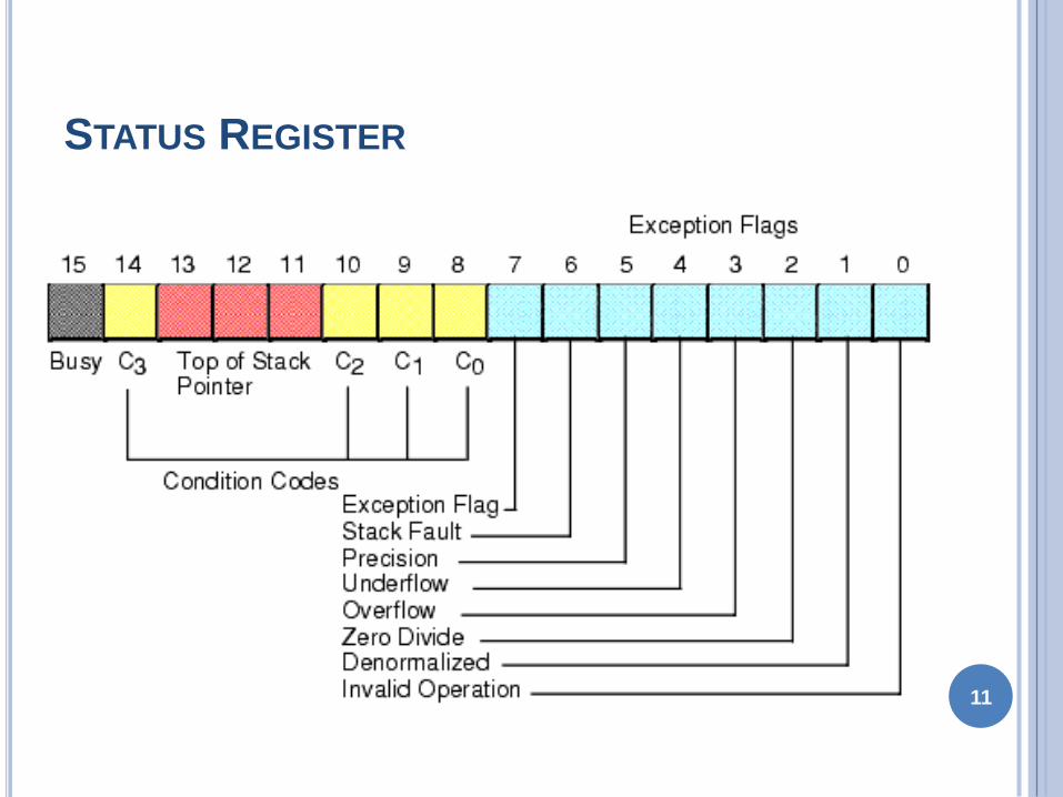
STATUS REGISTER
Stack Fault It is not available in 8087 It is active
only in 80387 and above
Precision It indicates that the result has exceeded
the selected precision
Underflow It tells if the result is too small to fit in a
register
Overflow It tells if the result is too large to fit in a
register14
STATUS REGISTER
Zero Divide It indicates that you try to divide a
non-zero value by zero
Denormalized It indicates that at least one of the
operand is de-normalized
Invalid Operation It indicates an invalid operation
For eg pushing more than eight items onto the
stack attempting to pop an item off an empty stack
or taking the square root of a negative number15
CONTROL REGISTER
16
CONTROL REGISTER
Control Register controls the operating modes of 8087
It is also a 16-bit register
It performs rounding control and precision control
It is also used to do masking and unmasking of the
exception bits that correspond to the rightmost six bits
of the status register
FLDCW instruction is used to load the value into control
register17
CONTROL REGISTER
Rounding Control It determines the type of rounding or truncating to be done
00=Round to nearest or even01=Round down towards minus infinity10=Round up towards plus infinity11=Chop or truncate towards zero
Precision Control It sets the precision of the result
00=Single precision (short)01=Reserved10=Double precision (long)11=Extended precision (temporary)
Exception Masks It determines that whether an error effects the exception bits in the status register
If it is one then the corresponding error is ignored
If it is zero and the corresponding error occurs then it generates an interrupt and the corresponding bit in status register is set
18
TAG REGISTER
19
Tag Values
00 = Valid
01 = Zero
10 = Invalid
11 = Empty
TAG 7 TAG 6 TAG 5 TAG 4 TAG 3 TAG 2 TAG 1 TAG 0
TAG REGISTER
Tag Register is used to indicate the contents of
each register in the stack
There are total 8 tags (Tag 0 to Tag 7) in this
register and each tag uses 2 bits to represent a
value
Therefore it is a 16-bit register
20
Tag Values
00 = Valid
01 = Zero
10 = Invalid
11 = Empty
TAG 7 TAG 6 TAG 5 TAG 4 TAG 3 TAG 2 TAG 1 TAG 0
PIN DIAGRAM OF 8087
21
8
0
8
7
GND
GND
CLK
NC
NC
AD0
AD1
AD2
AD3
AD4
AD5
AD6
AD7
AD8
AD9
AD10
AD11
AD12
AD13
AD14
VCC
AD15
A16S3
A17S4
A18S5
A19S6
BHES7
RQGT1
INT
RQGT0
NC
NC
S2
S1
S0
QS0
QS1
BUSY
READY
RESET
INTERFACING OF 8086 AND 8087
Multiplexed address-data bus lines are connected
directly from 8086 to 8087
The status lines and the queue status lines are
connected directly from 8086 to 8087
The RequestGrant (RQGT0 and RQGT1) signals
of 8087 are connected to RQGT0 and RQGT1 of
8086
BUSY signal of 8087 is connected to TEST pin of
8086
22
EXCEPTION HANDLING
The 8087 detects six different types of exception
conditions that occur during instruction execution
These will cause an interrupt if unmasked and
interrupts are enabled
1) INVALID OPERATION
2) OVERFLOW
3) ZERO DIVISOR
4) UNDERFLOW
5) DENORMALIZED OPERAND
6) INEXACT RESULT23
SYNCHRONIZATION BETWEEN 8086 AND 8087
24
Escape
Activate
Test Pin
Execute
8086
Instruction
Wait
Deactivate
Test Pin
Monitor
8086Wake up Co-processor
Wakeup 8086
8086 8087
DATA TYPES
Internally all data operands are converted to the
80-bit temporary real format
We have 3 types
bullInteger data type
bullPacked BCD data type
bullReal data type
25
INSTRUCTION SET
The 8087 instruction mnemonics begins with the
letter F which stands for Floating
point and distinguishes from 8086
The 8087 detects an error condition usually called
an exception when it executing an
instruction it will set the bit in its Status register
Types
I DATA TRANSFER INSTRUCTIONS
II ARITHMETIC INSTRUCTIONS
III COMPARE INSTRUCTIONS
20
-No
v-1
0
26
ww
we
azyn
ote
sc
om
DATA TRANSFERS INSTRUCTIONS
REAL TRANSFER
FLD Load real
FST Store real
FSTP Store real and pop
FXCH Exchange registers
INTEGER TRANSFER
FILD Load integer
FIST Store integer
FISTP Store integer and pop 27
FLD Source- Decrements the stack pointer by
one and copies a real number from a
stack element or memory location to the new ST
bullFLD ST(3) Copies ST(3) to ST
bullFLD LONG_REAL[BX] Number from memory
copied to ST
FLD Destination- Copies ST to a specified stack
position or to a specified memory location
bullFST ST(2) Copies ST to ST(2)and increment
stack pointer
bullFST SHORT_REAL[BX] Copy ST to a memory at
a SHORT_REAL[BX]
28
1048766 FXCH Destination ndash Exchange the contents
of ST with the contents of a specified
stack element
bullFXCH ST(5) Swap ST and ST(5)
20
-No
v-1
0
29
ww
we
azyn
ote
sc
om
FILD Source ndash Integer load Convert integer
number from memory to temporary-real
sformat and push on 8087 stack
bullFILD DWORD PTR[BX] Short integer from
memory at [BX]
FIST Destination- Integer store Convert number
from ST to integer and copy to memory
bullFIST LONG_INT ST to memory locations named
LONG_INT
20
-No
v-1
0
30
ww
we
azyn
ote
sc
om
ARITHMETIC INSTRUCTIONSFOUR BASIC ARITHMETIC FUNCTIONS
ADDITION SUBTRACTION MULTIPLICATION AND
DIVISION
Addition
FADD Add real
FADDP Add real and pop
FIADD Add integer
Subtraction
FSUB Subtract real
FSUBP Subtract real and pop
FISUB Subtract integer
31
Multiplication
FMUL Multiply real
FMULP Multiply real and pop
FIMUL Multiply integer
Advanced
FABS Absolute value
FCHS Change sign
FPREM Partial remainder
FPRNDINT Round to integer
FSCALE Scale
FSQRT Square root
FXTRACT Extract exponent and mantissa
20
-No
v-1
0
32
ww
we
azyn
ote
sc
om
FADD ST(3) ST Add ST to ST(3) result in ST(3)
bullFADD STST(4) Add ST(4) to ST result in ST
bullFADD ST + ST(1) pop stack result at ST
bullFADDP ST(1) Add ST(1) to ST Increment stack pointer so
ST(1) become ST
bullFSUB ST(2) ST ST(2)=ST(2) ndash ST
bullFSUB Rate ST=ST ndash real no from memory
bullFSUB ST=( ST(1) ndash ST)
FSUBP - Subtract ST from specified stack element and put
result in specified stack
element Then increment the pointer by one
bullFSUBP ST(1) ST(1)-ST ST(1) becomes new ST
33
COMPARE INSTRUCTIONS
FCOM Compare real
FCOMP Compare real and pop
FCOMPP Compare real and pop twice
FICOM Compare integer
FICOMP Compare integer and pop
FTST Test ST against +00
FXAM Examine ST
Transcendental Instruction
34
35
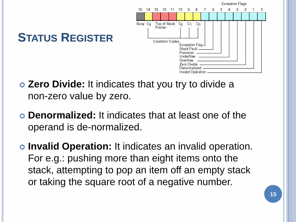
STATUS REGISTER
Zero Divide It indicates that you try to divide a
non-zero value by zero
Denormalized It indicates that at least one of the
operand is de-normalized
Invalid Operation It indicates an invalid operation
For eg pushing more than eight items onto the
stack attempting to pop an item off an empty stack
or taking the square root of a negative number15
CONTROL REGISTER
16
CONTROL REGISTER
Control Register controls the operating modes of 8087
It is also a 16-bit register
It performs rounding control and precision control
It is also used to do masking and unmasking of the
exception bits that correspond to the rightmost six bits
of the status register
FLDCW instruction is used to load the value into control
register17
CONTROL REGISTER
Rounding Control It determines the type of rounding or truncating to be done
00=Round to nearest or even01=Round down towards minus infinity10=Round up towards plus infinity11=Chop or truncate towards zero
Precision Control It sets the precision of the result
00=Single precision (short)01=Reserved10=Double precision (long)11=Extended precision (temporary)
Exception Masks It determines that whether an error effects the exception bits in the status register
If it is one then the corresponding error is ignored
If it is zero and the corresponding error occurs then it generates an interrupt and the corresponding bit in status register is set
18
TAG REGISTER
19
Tag Values
00 = Valid
01 = Zero
10 = Invalid
11 = Empty
TAG 7 TAG 6 TAG 5 TAG 4 TAG 3 TAG 2 TAG 1 TAG 0
TAG REGISTER
Tag Register is used to indicate the contents of
each register in the stack
There are total 8 tags (Tag 0 to Tag 7) in this
register and each tag uses 2 bits to represent a
value
Therefore it is a 16-bit register
20
Tag Values
00 = Valid
01 = Zero
10 = Invalid
11 = Empty
TAG 7 TAG 6 TAG 5 TAG 4 TAG 3 TAG 2 TAG 1 TAG 0
PIN DIAGRAM OF 8087
21
8
0
8
7
GND
GND
CLK
NC
NC
AD0
AD1
AD2
AD3
AD4
AD5
AD6
AD7
AD8
AD9
AD10
AD11
AD12
AD13
AD14
VCC
AD15
A16S3
A17S4
A18S5
A19S6
BHES7
RQGT1
INT
RQGT0
NC
NC
S2
S1
S0
QS0
QS1
BUSY
READY
RESET
INTERFACING OF 8086 AND 8087
Multiplexed address-data bus lines are connected
directly from 8086 to 8087
The status lines and the queue status lines are
connected directly from 8086 to 8087
The RequestGrant (RQGT0 and RQGT1) signals
of 8087 are connected to RQGT0 and RQGT1 of
8086
BUSY signal of 8087 is connected to TEST pin of
8086
22
EXCEPTION HANDLING
The 8087 detects six different types of exception
conditions that occur during instruction execution
These will cause an interrupt if unmasked and
interrupts are enabled
1) INVALID OPERATION
2) OVERFLOW
3) ZERO DIVISOR
4) UNDERFLOW
5) DENORMALIZED OPERAND
6) INEXACT RESULT23
SYNCHRONIZATION BETWEEN 8086 AND 8087
24
Escape
Activate
Test Pin
Execute
8086
Instruction
Wait
Deactivate
Test Pin
Monitor
8086Wake up Co-processor
Wakeup 8086
8086 8087
DATA TYPES
Internally all data operands are converted to the
80-bit temporary real format
We have 3 types
bullInteger data type
bullPacked BCD data type
bullReal data type
25
INSTRUCTION SET
The 8087 instruction mnemonics begins with the
letter F which stands for Floating
point and distinguishes from 8086
The 8087 detects an error condition usually called
an exception when it executing an
instruction it will set the bit in its Status register
Types
I DATA TRANSFER INSTRUCTIONS
II ARITHMETIC INSTRUCTIONS
III COMPARE INSTRUCTIONS
20
-No
v-1
0
26
ww
we
azyn
ote
sc
om
DATA TRANSFERS INSTRUCTIONS
REAL TRANSFER
FLD Load real
FST Store real
FSTP Store real and pop
FXCH Exchange registers
INTEGER TRANSFER
FILD Load integer
FIST Store integer
FISTP Store integer and pop 27
FLD Source- Decrements the stack pointer by
one and copies a real number from a
stack element or memory location to the new ST
bullFLD ST(3) Copies ST(3) to ST
bullFLD LONG_REAL[BX] Number from memory
copied to ST
FLD Destination- Copies ST to a specified stack
position or to a specified memory location
bullFST ST(2) Copies ST to ST(2)and increment
stack pointer
bullFST SHORT_REAL[BX] Copy ST to a memory at
a SHORT_REAL[BX]
28
1048766 FXCH Destination ndash Exchange the contents
of ST with the contents of a specified
stack element
bullFXCH ST(5) Swap ST and ST(5)
20
-No
v-1
0
29
ww
we
azyn
ote
sc
om
FILD Source ndash Integer load Convert integer
number from memory to temporary-real
sformat and push on 8087 stack
bullFILD DWORD PTR[BX] Short integer from
memory at [BX]
FIST Destination- Integer store Convert number
from ST to integer and copy to memory
bullFIST LONG_INT ST to memory locations named
LONG_INT
20
-No
v-1
0
30
ww
we
azyn
ote
sc
om
ARITHMETIC INSTRUCTIONSFOUR BASIC ARITHMETIC FUNCTIONS
ADDITION SUBTRACTION MULTIPLICATION AND
DIVISION
Addition
FADD Add real
FADDP Add real and pop
FIADD Add integer
Subtraction
FSUB Subtract real
FSUBP Subtract real and pop
FISUB Subtract integer
31
Multiplication
FMUL Multiply real
FMULP Multiply real and pop
FIMUL Multiply integer
Advanced
FABS Absolute value
FCHS Change sign
FPREM Partial remainder
FPRNDINT Round to integer
FSCALE Scale
FSQRT Square root
FXTRACT Extract exponent and mantissa
20
-No
v-1
0
32
ww
we
azyn
ote
sc
om
FADD ST(3) ST Add ST to ST(3) result in ST(3)
bullFADD STST(4) Add ST(4) to ST result in ST
bullFADD ST + ST(1) pop stack result at ST
bullFADDP ST(1) Add ST(1) to ST Increment stack pointer so
ST(1) become ST
bullFSUB ST(2) ST ST(2)=ST(2) ndash ST
bullFSUB Rate ST=ST ndash real no from memory
bullFSUB ST=( ST(1) ndash ST)
FSUBP - Subtract ST from specified stack element and put
result in specified stack
element Then increment the pointer by one
bullFSUBP ST(1) ST(1)-ST ST(1) becomes new ST
33
COMPARE INSTRUCTIONS
FCOM Compare real
FCOMP Compare real and pop
FCOMPP Compare real and pop twice
FICOM Compare integer
FICOMP Compare integer and pop
FTST Test ST against +00
FXAM Examine ST
Transcendental Instruction
34
35

CONTROL REGISTER
Rounding Control It determines the type of rounding or truncating to be done
00=Round to nearest or even01=Round down towards minus infinity10=Round up towards plus infinity11=Chop or truncate towards zero
Precision Control It sets the precision of the result
00=Single precision (short)01=Reserved10=Double precision (long)11=Extended precision (temporary)
Exception Masks It determines that whether an error effects the exception bits in the status register
If it is one then the corresponding error is ignored
If it is zero and the corresponding error occurs then it generates an interrupt and the corresponding bit in status register is set
18
TAG REGISTER
19
Tag Values
00 = Valid
01 = Zero
10 = Invalid
11 = Empty
TAG 7 TAG 6 TAG 5 TAG 4 TAG 3 TAG 2 TAG 1 TAG 0
TAG REGISTER
Tag Register is used to indicate the contents of
each register in the stack
There are total 8 tags (Tag 0 to Tag 7) in this
register and each tag uses 2 bits to represent a
value
Therefore it is a 16-bit register
20
Tag Values
00 = Valid
01 = Zero
10 = Invalid
11 = Empty
TAG 7 TAG 6 TAG 5 TAG 4 TAG 3 TAG 2 TAG 1 TAG 0
PIN DIAGRAM OF 8087
21
8
0
8
7
GND
GND
CLK
NC
NC
AD0
AD1
AD2
AD3
AD4
AD5
AD6
AD7
AD8
AD9
AD10
AD11
AD12
AD13
AD14
VCC
AD15
A16S3
A17S4
A18S5
A19S6
BHES7
RQGT1
INT
RQGT0
NC
NC
S2
S1
S0
QS0
QS1
BUSY
READY
RESET
INTERFACING OF 8086 AND 8087
Multiplexed address-data bus lines are connected
directly from 8086 to 8087
The status lines and the queue status lines are
connected directly from 8086 to 8087
The RequestGrant (RQGT0 and RQGT1) signals
of 8087 are connected to RQGT0 and RQGT1 of
8086
BUSY signal of 8087 is connected to TEST pin of
8086
22
EXCEPTION HANDLING
The 8087 detects six different types of exception
conditions that occur during instruction execution
These will cause an interrupt if unmasked and
interrupts are enabled
1) INVALID OPERATION
2) OVERFLOW
3) ZERO DIVISOR
4) UNDERFLOW
5) DENORMALIZED OPERAND
6) INEXACT RESULT23
SYNCHRONIZATION BETWEEN 8086 AND 8087
24
Escape
Activate
Test Pin
Execute
8086
Instruction
Wait
Deactivate
Test Pin
Monitor
8086Wake up Co-processor
Wakeup 8086
8086 8087
DATA TYPES
Internally all data operands are converted to the
80-bit temporary real format
We have 3 types
bullInteger data type
bullPacked BCD data type
bullReal data type
25
INSTRUCTION SET
The 8087 instruction mnemonics begins with the
letter F which stands for Floating
point and distinguishes from 8086
The 8087 detects an error condition usually called
an exception when it executing an
instruction it will set the bit in its Status register
Types
I DATA TRANSFER INSTRUCTIONS
II ARITHMETIC INSTRUCTIONS
III COMPARE INSTRUCTIONS
20
-No
v-1
0
26
ww
we
azyn
ote
sc
om
DATA TRANSFERS INSTRUCTIONS
REAL TRANSFER
FLD Load real
FST Store real
FSTP Store real and pop
FXCH Exchange registers
INTEGER TRANSFER
FILD Load integer
FIST Store integer
FISTP Store integer and pop 27
FLD Source- Decrements the stack pointer by
one and copies a real number from a
stack element or memory location to the new ST
bullFLD ST(3) Copies ST(3) to ST
bullFLD LONG_REAL[BX] Number from memory
copied to ST
FLD Destination- Copies ST to a specified stack
position or to a specified memory location
bullFST ST(2) Copies ST to ST(2)and increment
stack pointer
bullFST SHORT_REAL[BX] Copy ST to a memory at
a SHORT_REAL[BX]
28
1048766 FXCH Destination ndash Exchange the contents
of ST with the contents of a specified
stack element
bullFXCH ST(5) Swap ST and ST(5)
20
-No
v-1
0
29
ww
we
azyn
ote
sc
om
FILD Source ndash Integer load Convert integer
number from memory to temporary-real
sformat and push on 8087 stack
bullFILD DWORD PTR[BX] Short integer from
memory at [BX]
FIST Destination- Integer store Convert number
from ST to integer and copy to memory
bullFIST LONG_INT ST to memory locations named
LONG_INT
20
-No
v-1
0
30
ww
we
azyn
ote
sc
om
ARITHMETIC INSTRUCTIONSFOUR BASIC ARITHMETIC FUNCTIONS
ADDITION SUBTRACTION MULTIPLICATION AND
DIVISION
Addition
FADD Add real
FADDP Add real and pop
FIADD Add integer
Subtraction
FSUB Subtract real
FSUBP Subtract real and pop
FISUB Subtract integer
31
Multiplication
FMUL Multiply real
FMULP Multiply real and pop
FIMUL Multiply integer
Advanced
FABS Absolute value
FCHS Change sign
FPREM Partial remainder
FPRNDINT Round to integer
FSCALE Scale
FSQRT Square root
FXTRACT Extract exponent and mantissa
20
-No
v-1
0
32
ww
we
azyn
ote
sc
om
FADD ST(3) ST Add ST to ST(3) result in ST(3)
bullFADD STST(4) Add ST(4) to ST result in ST
bullFADD ST + ST(1) pop stack result at ST
bullFADDP ST(1) Add ST(1) to ST Increment stack pointer so
ST(1) become ST
bullFSUB ST(2) ST ST(2)=ST(2) ndash ST
bullFSUB Rate ST=ST ndash real no from memory
bullFSUB ST=( ST(1) ndash ST)
FSUBP - Subtract ST from specified stack element and put
result in specified stack
element Then increment the pointer by one
bullFSUBP ST(1) ST(1)-ST ST(1) becomes new ST
33
COMPARE INSTRUCTIONS
FCOM Compare real
FCOMP Compare real and pop
FCOMPP Compare real and pop twice
FICOM Compare integer
FICOMP Compare integer and pop
FTST Test ST against +00
FXAM Examine ST
Transcendental Instruction
34
35
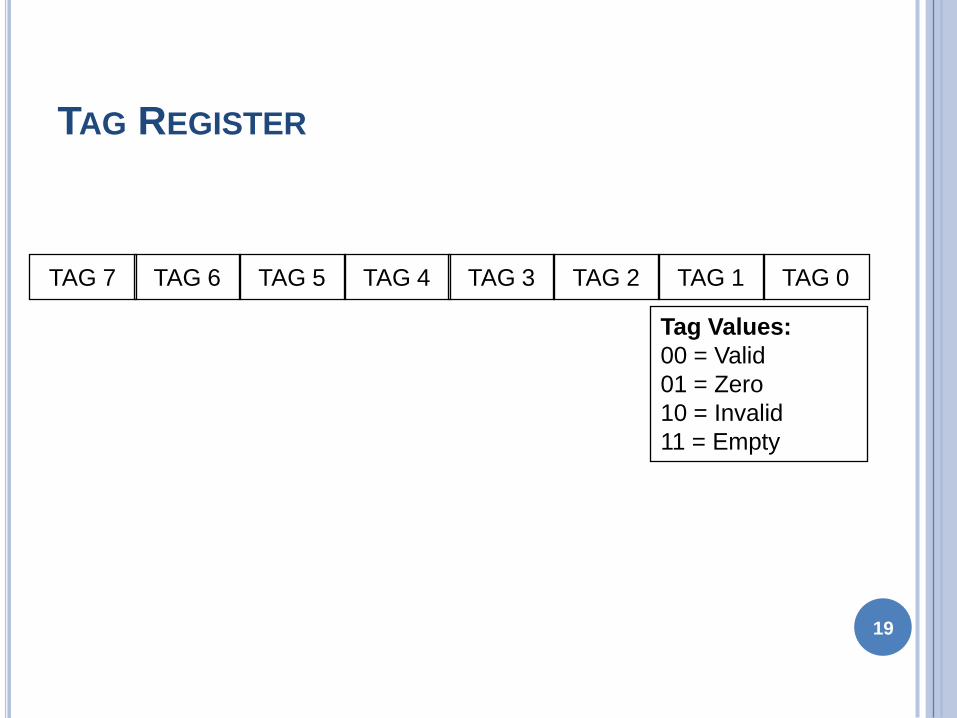
TAG REGISTER
Tag Register is used to indicate the contents of
each register in the stack
There are total 8 tags (Tag 0 to Tag 7) in this
register and each tag uses 2 bits to represent a
value
Therefore it is a 16-bit register
20
Tag Values
00 = Valid
01 = Zero
10 = Invalid
11 = Empty
TAG 7 TAG 6 TAG 5 TAG 4 TAG 3 TAG 2 TAG 1 TAG 0
PIN DIAGRAM OF 8087
21
8
0
8
7
GND
GND
CLK
NC
NC
AD0
AD1
AD2
AD3
AD4
AD5
AD6
AD7
AD8
AD9
AD10
AD11
AD12
AD13
AD14
VCC
AD15
A16S3
A17S4
A18S5
A19S6
BHES7
RQGT1
INT
RQGT0
NC
NC
S2
S1
S0
QS0
QS1
BUSY
READY
RESET
INTERFACING OF 8086 AND 8087
Multiplexed address-data bus lines are connected
directly from 8086 to 8087
The status lines and the queue status lines are
connected directly from 8086 to 8087
The RequestGrant (RQGT0 and RQGT1) signals
of 8087 are connected to RQGT0 and RQGT1 of
8086
BUSY signal of 8087 is connected to TEST pin of
8086
22
EXCEPTION HANDLING
The 8087 detects six different types of exception
conditions that occur during instruction execution
These will cause an interrupt if unmasked and
interrupts are enabled
1) INVALID OPERATION
2) OVERFLOW
3) ZERO DIVISOR
4) UNDERFLOW
5) DENORMALIZED OPERAND
6) INEXACT RESULT23
SYNCHRONIZATION BETWEEN 8086 AND 8087
24
Escape
Activate
Test Pin
Execute
8086
Instruction
Wait
Deactivate
Test Pin
Monitor
8086Wake up Co-processor
Wakeup 8086
8086 8087
DATA TYPES
Internally all data operands are converted to the
80-bit temporary real format
We have 3 types
bullInteger data type
bullPacked BCD data type
bullReal data type
25
INSTRUCTION SET
The 8087 instruction mnemonics begins with the
letter F which stands for Floating
point and distinguishes from 8086
The 8087 detects an error condition usually called
an exception when it executing an
instruction it will set the bit in its Status register
Types
I DATA TRANSFER INSTRUCTIONS
II ARITHMETIC INSTRUCTIONS
III COMPARE INSTRUCTIONS
20
-No
v-1
0
26
ww
we
azyn
ote
sc
om
DATA TRANSFERS INSTRUCTIONS
REAL TRANSFER
FLD Load real
FST Store real
FSTP Store real and pop
FXCH Exchange registers
INTEGER TRANSFER
FILD Load integer
FIST Store integer
FISTP Store integer and pop 27
FLD Source- Decrements the stack pointer by
one and copies a real number from a
stack element or memory location to the new ST
bullFLD ST(3) Copies ST(3) to ST
bullFLD LONG_REAL[BX] Number from memory
copied to ST
FLD Destination- Copies ST to a specified stack
position or to a specified memory location
bullFST ST(2) Copies ST to ST(2)and increment
stack pointer
bullFST SHORT_REAL[BX] Copy ST to a memory at
a SHORT_REAL[BX]
28
1048766 FXCH Destination ndash Exchange the contents
of ST with the contents of a specified
stack element
bullFXCH ST(5) Swap ST and ST(5)
20
-No
v-1
0
29
ww
we
azyn
ote
sc
om
FILD Source ndash Integer load Convert integer
number from memory to temporary-real
sformat and push on 8087 stack
bullFILD DWORD PTR[BX] Short integer from
memory at [BX]
FIST Destination- Integer store Convert number
from ST to integer and copy to memory
bullFIST LONG_INT ST to memory locations named
LONG_INT
20
-No
v-1
0
30
ww
we
azyn
ote
sc
om
ARITHMETIC INSTRUCTIONSFOUR BASIC ARITHMETIC FUNCTIONS
ADDITION SUBTRACTION MULTIPLICATION AND
DIVISION
Addition
FADD Add real
FADDP Add real and pop
FIADD Add integer
Subtraction
FSUB Subtract real
FSUBP Subtract real and pop
FISUB Subtract integer
31
Multiplication
FMUL Multiply real
FMULP Multiply real and pop
FIMUL Multiply integer
Advanced
FABS Absolute value
FCHS Change sign
FPREM Partial remainder
FPRNDINT Round to integer
FSCALE Scale
FSQRT Square root
FXTRACT Extract exponent and mantissa
20
-No
v-1
0
32
ww
we
azyn
ote
sc
om
FADD ST(3) ST Add ST to ST(3) result in ST(3)
bullFADD STST(4) Add ST(4) to ST result in ST
bullFADD ST + ST(1) pop stack result at ST
bullFADDP ST(1) Add ST(1) to ST Increment stack pointer so
ST(1) become ST
bullFSUB ST(2) ST ST(2)=ST(2) ndash ST
bullFSUB Rate ST=ST ndash real no from memory
bullFSUB ST=( ST(1) ndash ST)
FSUBP - Subtract ST from specified stack element and put
result in specified stack
element Then increment the pointer by one
bullFSUBP ST(1) ST(1)-ST ST(1) becomes new ST
33
COMPARE INSTRUCTIONS
FCOM Compare real
FCOMP Compare real and pop
FCOMPP Compare real and pop twice
FICOM Compare integer
FICOMP Compare integer and pop
FTST Test ST against +00
FXAM Examine ST
Transcendental Instruction
34
35
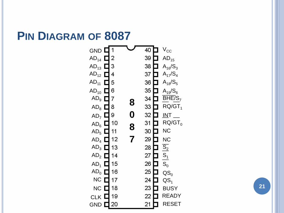
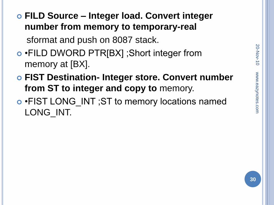
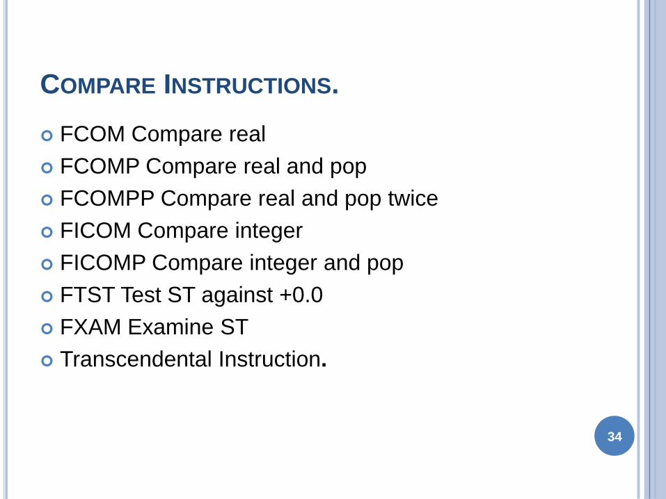
COMPARE INSTRUCTIONS
FCOM Compare real
FCOMP Compare real and pop
FCOMPP Compare real and pop twice
FICOM Compare integer
FICOMP Compare integer and pop
FTST Test ST against +00
FXAM Examine ST
Transcendental Instruction
34
35

35


