Download - MAY 0 A2018 fTiyox@soutfiernco

j.l_ Kl I MichaelJ. Yox 7825 River RoadjOUtnCrn NUCl0dr Regulatory Affairs Director Waynesboro, GA 30830
Vogtle3&4 706-848-6459 tel410-474-8587 cell
MAY 0 A 2018 [email protected]
Docket Nos.: 52-025
52-026
ND-18-0618
10CFR 52.99(c)(3)
U.S. Nuclear Regulatory CommissionDocument Control Desk
Washington, DC 20555-0001
Southern Nuclear Operating CompanyVogtle Electric Generating Plant Unit 3 and Unit 4
Notice of Uncompleted ITAAC 225-davs Prior to Initial Fuel LoadItem 3.3.00.03a [Index Number 7771
Ladies and Gentlemen:
Pursuant to 10 CFR 52.99(c)(3), Southern NuclearOperating Company hereby notifies the NRCthat as of May 1, 2018, Vogtle Electric Generating Plant (VEGP) Unit 3 and Unit 4 UncompletedInspections, Tests, Analyses, and Acceptance Criteria (ITAAC) Item 3.3.00.03a [Index Number 777]has not been completed greater than 225-days prior to initial fuel load. The Enclosure describesthe plan for completing this ITAAC. Southern Nuclear Operating Company will, at a later date,provide additional notifications for ITAAC that have not been completed 225-days prior to initial fuelload.
This notification is informed by the guidance described in NEI 08-01, Industry Guideline for theITAAC Closure Process Under 10 CFR Part 52, which was endorsed by the NRC in RegulatoryGuide 1.215. In accordance with NEI 08-01, this notification includes ITAAC for which requiredinspections, tests, or analyses have not been performed or have been only partially completed. AllITAAC will be fully completed and all Section 52.99(c)(1) ITAAC Closure Notifications will besubmitted to NRC to support the Commission finding that all acceptance criteria are met prior toplant operation, as required by 10 CFR 52.103(g).
This letter contains no new NRC regulatory commitments.
If there are any questions, please contact Tom Petrak at 706-848-1575.
Respectfully submitted,\
Michael J. YoxRegulatory Affairs Direcfor Vogtle 3 &4
Enclosure: Vogtle Electric Generating Plant (VEGP) Unit 3 and Unit 4Completion Plan for Uncompleted ITAAC 3.3.00.03a [Index Number 777]
MJY/KJD/amw

U.S. Nuclear Regulatory CommissionND-18-0618
Page 2 of 3
To:
Southern Nuclear Operating Company/ Georgia Power CompanyMr. D. A. Bost (w/o enclosures)Mr. M. D. Rauckhorst (w/o enclosures)Mr. M. D. Meier
Mr. D. H. Jones (w/o enclosures)Mr. D. L. McKlnneyMr. M. J. Yox
Mr. D. L. Fulton
Mr. J. B. Klecha
Mr. G. Chick
Mr. F. H. Willis
Ms. A. L. PughMr. A. 8. Parton
Mr. W. A. SparkmanMr. C. E. Morrow
Ms. K. M. StacyMr. M. K. WashingtonMr. J. P. Redd
Ms. A. C. Chamberlain
Mr. D. R. Culver
Mr. T. G. Petrak
Document Services RTYPE; VND.LI.L06
File AR.01.02.06
cc:
Nuclear Regulatory Commission
Mr. W. Jones (w/o enclosures)Ms. J. M. Heisserer
Mr. C. P. Patel
Mr. M. E. Ernstes
Mr. G. J. Khouri
Mr. T. E. Chandler
Ms. S. E. TempleMs. P. Braxton
Mr. N. D. Karlovich
Mr. A. J. Lerch
Mr. C. J. Even
Mr. F. D. Brown
Mr. B. J. Kemker
Ms. A. E. Rivera-Varona
Ms. L. A. Kent
Mr. P. B. DonnellyMs. N. C. Coovert
Oalethoroe Power CorporationMr. R. B. Brinkman

U.S. Nuclear Regulatory CommissionND-18-0618
Page 3 of 3
Municipal Electric Authority of GeorgiaMr. J. E. Fuller
Mr. 8. M. Jackson
Dalton Utilities
Mr. T. Bundros
Westinqhouse Electric Company. LLCDr. L. Orlani (w/o enclosures)Mr. D. C. Durham (w/o enclosures)Mr. M. M. Corletti
Ms. L. G. Iller
Mr. D. Hawkins
Ms. J. Monahan
Mr. J. L. Coward
Ms. N. E. Deangelis
Other
Mr. J. E. Hesler, Bechtel Power CorporationMs. L. Matis, Tetra Tech NUS, Inc.Dr. W. R. Jacobs, Jr., Ph.D., CDS Associates, Inc.Mr. 8. Roetger, Georgia Public Service CommissionMs. 8. W. Kernizan, Georgia Public Service CommissionMr. K. C. Greene, Troutman SandersMr. 8. Blanton, Balch BIngham

U.S. Nuclear Regulatory CommissionND-18-0618 Enclosure
Page 1 of 7
Southern Nuclear Operating CompanyND-18-0618
Enclosure
Vogtle Electric Generating Plant (VEGP) Unit 3 and Unit 4Completion Plan for Uncompleted ITAAC 3.3.00.03a [Index Number 777]

U.S. Nuclear Regulatory CommissionND-18-0618 Enclosure
Page 2 of 7
ITAAC Statement
Desion Commitment
3. Walls and floors of the nuclear island structures as defined on Table 3.3-1 except fordesigned openings or penetrations provide shielding during normal operations.
Insoections/Tests/Analvses
Inspection of the as-built nuclear island structureswall and floor thicknesses will be performed.
Acceptance Criteria
a) A report exists and concludes that the shield walls and floors of the containmentintemal structures as defined in Table 3.3-1, except for designed openings or penetrations, areconsistent with the concrete wall thicknesses provided in Table 3.3-1.
ITAAC Completion Description
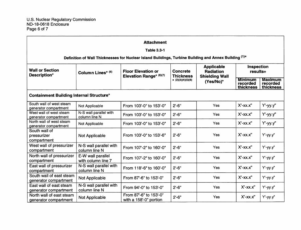
Multiple ITAAC are performed to verify that the walls of the nuclear island structures as definedon Combined License (COL) Appendix C, Table 3.3-1 except for designed openings orpenetrations provide radiation shielding during normal operation. The subject ITAAC requiresan inspection ofthe as-built shield walls and floors of the containment internal structurestoverify they are consistent with the concrete wall thicknesses provided in COL Appendix C, Table3.3-1, which is summarized in the Attachment.
The inspections are performed ofthe as-built sections (following concrete placement) inaccordancewith the requirements ofmeasurement guideline APP-GW-IT-001 (Reference 1),which identifies the location and frequency of inspection points for determining wall thickness toensure the resulting measurements are representative ofthe entire section being inspected.The measurements are based on the size and construction type of each section. Measurementsare taken usingsurvey equipment inaccordance with site survey procedures.
The inspection results are documented in the Unit 3 and Unit 4 principal closure documents(References 2 and3, respectively) andsummarized in theAttachment which meets the ITAACacceptance criteria.
References 1 thru 3 are available for NRG inspeciton as part of the Unit 3 and Unit 4 ITAAC3.3.00.03a Completion Packages (Reference 4 and 5, respectively).
List of ITAAC Findings
In accordance with plant procedures for ITAAC completion, Southern NuclearOperatingCompany (SNC) performed a review ofall findings pertaining to the subject ITAAC andassociated corrective actions. This review found there are no relevant ITAAC findingsassociated with this ITAAC.

U.S. Nuclear Regulatory CommissionND-18-0618 Enclosure
Page 3 of 7
References favailable for NRG inspection)
1. APP-GW-IT-001, Revision 0, "Guidelines for Concrete Wall and Slab ThicknessMeasurements"
2. Principal Closure Document (Unit 3)3. Principal Closure Document (Unit 4)4. 3.3.00.03a U3-CP-Rev 0 ITAAC Completion Package5. 3.3.00.03a U4-CP-Rev 0 ITAAC Completion Package6. NEI 08-01, "Industry Guideline for the ITAAC Closure Process under 10 CFR Part 52"

U.S. Nuclear Regulatory CommissionND-18-0618 Enclosure
Page 4 of 7
Attachment
Table 3.3-1
Definition of Wall Thicknesses for Nuclear Island Buildings, Turbine Buiiding and Annex Buiiding
Wall or Section
Description*Column Lines* Floor Elevation or
Elevation Range*Concrete
Thickness* (2)(3)(4)(5)(8)
ApplicableRadiation
Shielding Wall(Yes/No)*
Inspectionresults+
Minimumrecordedthickness
Maximumrecordedthickness
Containment Building Internal Structure*
Shield Wall between
Reactor Vessel Cavity andROOT Room
E-W wall parallel withcolumn line 7 (Insideface is 3'-0" north of
column line 7. Widthof wall section with
stated thickness is
defined by inside wallof reactor vessel
cavity.)
From 71'-6" to 83'-0" Yes X'-xx.x" Y'-yy.y
West Reactor Vessel
Cavity Wall
N-S wall parallel withcolumn line N (Widthof wall section with
stated thickness is
defined by inside wallof reactor vessel
cavity.)
From 83'-0" to 98'-0" Yes X'-xx.x" Y'-yy.y"

U.S. Nuclear Regulatory CommissionND-18-0618 Enclosure
Page 5 of 7
Attachment
Table 3.3-1
Definition of Wall Thicknesses for Nuciear Isiand Buiidings, Turbine Building and Annex Building
Wall or Section
Description* Column Lines* Floor Elevation or
Elevation Range*Concrete
Thickness* (2)(3)(4)(5)(8)
ApplicableRadiation
Shielding Wall(Yes/No)*
Inspectionresults+
Minimumrecordedthickness
Maximumrecordedthickness
Containment Building Internal Structure*
North Reactor Vessel
Cavity Wall
E-W wall parallel withcolumn line 7 (Width ofwall section with stated
thickness is defined byInside wall of reactor
vessel cavity.)
From 83'-0" to 98'-0" Yes X'-xx.x" Y'-yy.y"
East Reactor Vessel
Cavity Wall
N-S wall parallel withcolumn line N (Widthof wall section with
stated thickness is
defined by inside wallof reactor vessel
cavity.)
From 83'-0" to 98'-0" 7'-6"(9) Yes X'-xx.x" Y'-yy.y"
West Refueling CavityWall
N-S wall parallel withcolumn line N
From 98'-0" to 135'-3" 4'-0" Yes X'-xx.x" Y'-yy.y"
North Refueling CavityWall
E-W wall parallel withcolumn line 7
From 98'-0" to 135'-3" 4'-0" Yes X'-xx.x" Y'-yy.y"
East Refueling Cavity WallN-S wall parallel withcolumn line N
From 98'-0" to 135'-3" 4'-0" Yes X'-xx.x" Y'-yy.y"
South Refueling CavityWall
E-W wall parallel withcolumn line 7
From 98'-0" to 135'-3" 4'-0" Yes X'-xx.x" Y'-yy.y"
U.S. Nuclear Regulatory CommissionND-18-0618 Enclosure
Page 6 of 7
Attachment
Table 3.3-1
Definition of Wall Thicknesses for Nuclear island Buildings, Turbine Building and Annex Building
Wall or Section
Description* Column Lines* Floor Elevation or
Elevation Range*Concrete
Thickness* (2)(3)(4)(5)(8)
ApplicableRadiation
Shielding Waii(Yes/No)*
inspectionresults-f
Minimumrecordedthickness
Maximumrecordedthickness
Containment Building Internai Structure*
South wall of west steam
generator compartmentNot Applicable From 103'-0" to 153'-0" 2'-6" Yes X'-xx.x" Y'-yy.y"
West wall of west steam
generator compartmentN-S wall parallel withcolumn line N
From 103'-0" to 153'-0" 2'-6" Yes X'-xx.x" Y'-yy.y"
North wall of west steam
generator compartmentNot Applicable From 103'-0" to 153'-0" 2'-6" Yes X'-xx.x" Y'-yy.y"
South wall of
pressurizercompartment
Not Applicable From 103'-0"to 153'-6" 2'-6" Yes X'-xx.x" Y'-yy.y
West wall of pressurizercompartment
N-S wall parallel withcolumn line N
From 107'-2" to 160'-0" 2'-6" Yes X'-xx.x" Y'-yy.y
North wall of pressurizercompartment
E-W wall parallelwith column line 7
From 107'-2" to160'-0" 2'-6" Yes X'-xx.x" Y'-yy.y
East wall of pressurizercompartment
N-S wall parallel withcolumn line N
From 118'-6"to 160'-0" 2'-6" Yes X'-xx.x" Y'-yy.y
South wall of east steamgenerator compartment
Not Applicable From 87'-6" to 153'-0" 2'-6"' Yes X'-xx.x" Y'-yy.y
East wall of east steamgenerator compartment
N-S wall parallel withcolumn line N
From 94'-0" to 153'-0" 2'-6" Yes X'-xx.x" Y'-yy.y
North wall of east steam
generator compartmentNot Applicable
From 87'-6" to 153'-0"
with a 158'-0" portion2'-6" Yes X'-xx.x" Y'-yy.y

U.S. Nuclear Regulatory CommissionND-18-0618 Enclosure
Page 7 of 7
Notes:
* Excerp from COL Appendix C, Table 3.3-1
+ Inspection results will be Unit specific
1. Thie column lines and floor elevations are identified and included on COL Appendix C, Figures 3.3-1 through 3.3-13.
2. These wall (and floor) thicknesses have a construction tolerance of ± 1 inch, except as noted and for exterior walls below gradewhere the tolerance is +12 inches, -1 inch. These tolerances are not applicable to the nuclear island basemat.
3. For walls that are part of structural modules, the concrete thickness also includes the steel face plates. Where faceplates with anominal thickness of 0.5 inches are used in the construction of the wall modules, the wall thicknesses in this column apply. Wherefaceplates thicker than the nominal 0.5 inches are used in the construction of the structural wall modules, the wall thicknesses inthe area of the thicker faceplates are greater than indicated in this column by the amount of faceplate thickness increase overthe nominal 0.5 inches. Overlay plates are not considered part of the faceplates, and thus are not considered in the wailthicknesses identified in this column.
4. For floors with steel surface plates, the concrete thickness also includes the plate thickness.
5. Where a wall (or a floor) has openings, the concrete thickness does not apply at the opening.
6. The Wall or Section Description, Column Line information, and Floor Elevation or Elevation Ranges are provided as referencepoints to define the general location. The concrete thickness of an item intersecting other walls, roofs or floors at a designatedlocation (e.g., column line) is not intended to be measured to the stated column line, but only to the point where the intersectionoccurs.
7. Where applicable, the upper wall portions extend to their associated roofs, which may vary in elevation, e.g., sloped roofs.
8. From one wall/floor section to another, the concrete thickness transitions from one thickness to another, consistent with theconfigurations in Figures 3.3-1 through 3.3-14.
9. This wall thickness has a tolerance of ± 1-5/8 inch.


