Download - MI. utt - lss.fnal.gov

· Jl!IfJ
MI. Vi utt Q SEA
THE NUMERICAL DESIGN OF A RESONANT EXTRACTION SYSTEM
FOR THE MURA 50-MEV ELECTRON ACCELERATOR
Philip F. Meads, Jr.
NUMBER _7_12__REPORT

LEGA L NOTreE
This report was prepared as an account of Government sponsored work. Neither the United States, nor the Commission, nor any person acting on behalf of the Commission:
A. Makes any warranty or representation, expressed or implied, with. respect to the accuracy, completeness, or usefulness of the information contained in this report, or that the use of any information, apparatus, method, or process disclosed in this report may not infringe privately owned rights; or
B. Assumes any liabilities with respect to the use of, or for damages resulting from the use of any information, apparatus, method, or process disclosed in this report.
As used in the above, "person acting on behalf of the Commission" includes any employee or contractor of the Commission, or employee of such contractor, to the extent that such employee or contractor of the Commission, or employee of such contractor prepares, disseminates, or provides access to, any information pursuant tG his employment or contract with the Commission, or his employment with such contractor.
Printed in USA. PricE; $1. 75,_ Available from the Offic,~ of Technical Services, DepR.rtmen.J: of Commerc,~,
Washington 25, D. C.

·�
MURA-712 UC-28: Particle Accelerators and
High - Voltage Machines TID-4500 (37th Edition)
MIDWESTERN UNIVERSITIES RESEARCH ASSOCIA TION>:<
P. O. Box 6, Stoughton, Wisconsin
THE NUMERICAL DESIGN OF A RESONANT EXTRACTION SYSTEM
FOR THE MURA 50-MEV ELECTRON ACCELERATOR
Philip F. Meads, Jr.
March 1, 1965
ABSTRACT
Detailed numerical investigations of a proposed half-integral resonant-
extraction system for fixed-field, alternating-gradient synchrotrons verify
the feasibility of extracting a high-quality beam from the MURA 50-MeV
FFAG by this method. The half-integral resonance causes a large growth
in the radial betatron amplitude, enabling the extraction of virtually the entire
beam with an exceedingly small emittance. The method is complicated by the
inclusion of time-varying parameters, required to maintain a relatively
constant emittance and apparent source in the extracted beam over the extrac
,
tion interval. Calculations were performed on an IBM -704 digital computer
using measured magnetic fields.
>:<AEC Research and Development Report. Supported by the U. S. Atomic Energy Commission through ANL by Subcontract 31-109-38-1707.

2
I. INTRODUCTION
The resonant slow extraction of the beam of a fixed-field, alternating-
gradient accelerator has been the object of considerable interest. The experi
mental advantages of a many-turn extraction system are manifold- -particularly
in counter experiments •. Recently, the FFAG has been proposed as an injector
1 2for large synchrotrons.' The large currents available in a FFAG of moderate
energy are more than sufficient to fill existing and proposed alternating-gradient
synchrotrons to their space-charge limit. The best utilization of a FFAG
injector will be realized through the development of a resonant slow-extraction
scheme.
The basic theory of resonant extraction using a radial half-integral reso
nance is presented in the paper by C. L. Hammer and L. Jackson Laslett3 and
4that by Werner William Shoultz and C. L. Hammer. The object of the present
investigation is to develop the proposed extraction systems for the MURA 50 MeV
electron FFAG accelerator by means of extensive numerical calculations using
measured fields.
II. REVIEW OF LINEAR RESONANT EXTRACTION THEORY
This method of extraction consists of perturbing the magnetic field of
the accelerator to force the radial betatron oscillation frequency into the
nearest half-integral resonance (with the rotation frequency). When in reso
nance, the amplitude of betatron oscillations is no longer constrained, but
rather grows with time. All orbits are expressable as the sum of two in
dependent solutions to the radial betatron equation. In resonance, one of these
solutions increases exponentially while the other one exponentially decays.
3
After a sufficient time interval the decaying solution may be ignored; thus
all orbits, regardless of initial conditions, approach the increasing exponen
tial solution, differing only in amplitude. In particular, every particle
achieves its maximum displacement from the equilibrium orbit at the same
azimuth and with nearly the same angle with respect to the equilibrium orbit.
The azimuth of maximum displacement remains fixed with respect to time.
Upon reaching a certain amplitude at the chosen extraction azimuth, the
particles jump a septum and emerge from the machine with virtually no spread
in angle. In other words, the radial phase space of the extracted beam has an
exceedingly small area. In the limit of increasing time and amplitude, the
angular spread becomes arbitrarily small as the decaying exponential com
ponent of the orbits tends to zero. This property of the half-integral resonant
extraction system is particularly attractive when the extracted beam is to be
injected into another accelerator.
The azimuthal envelope of the betatron motion is strongly influenced by
the field perturbations. One of the goals of this study is to shape this envelope
so that the maximum radial spread of the beam occurs at the desired azimuth
and the beam is restrained from striking obstructions elsewhere in the accel
erator.
The radial width of the beam passing the septum depends upon the growth
rate at that amplitude. The larger this width, the higher is the extraction
efficiency as a correspondingly smaller fraction of the beam collides with the
septum. Thus, we seek to obtain a large growth rate at the septum amplitude.
This too is a function of the field perturbation chosen.
4�
The field perturbation also may shift the equilibrium orbit. If the
equilibrium orbit is shifted toward the center of the accelerator, the per
mitted spread of the beam at that azimuth is increased; this is desirable to
minimize the portion of the beam striking the septum. On the other hand,
shifting the equilibrium orbit outward at the extraction amplitude brings the
entire beam closer to the exterior of the machine, thus reducing the bending
field required to extract the beam.
Another consideration involved in choosing the shape of the perturbing
field is that of bringing the beam into the unstable region. Two approaches
are considered: (1) accelerating the beam into a dc perturbing field, and
(2) stacking the accelerated beam and then pulsing the perturbing field to
bring the beam out. The relative merits of these two approaches are discussed
subs equently.
All of the preceding arguments are based on a linear theory where in
fact FFAG accelerators are decidedly nonlinear. The nonlinear effects are
particularly important in resonant extraction studies because large radial beam
amplitudes are generated. Thus we surely must carefully consider the effect
of the nonlinear terms in selecting the shape of the perturbing field imposed
to extract the beam. It is for this reason that numerical studies are particularly
valuable.
Additional considerations involved in the selection of the type of field
perturbation are those of practicality. We would prefer that the perturbing
coils be inexpensive and easy to construct. The field must not be so compli
cated that overly critical adjustments are required for successful operation.

5
It is imperative that� the perturbation chosen have no adverse effect upon the
acceleration of the beam to the extraction energy lest there be no beam to
extract.
III. THE NUMERICAL METHODS APPLIED TO THE PROBLEM
A. Equations of Motion
Individual trajectories are calculated by integrating the following dif
ferential� equations with El as the independent variable:
- 1 21:dr
== r Pr (p2 _ P 2)� "Z d Pr == (p2 - P ) - r 'B zdEl r dEl r
1 dz = r Pz (p
2- P
2) -2 and
d Pz = ~Bz
- Pr (p2 _ p 2) -"Z ~Bz1 (1)zt 1
dEl r dEl ()r r ~El •
These equations depend upon the magnetic field in the median plane of the
accelerator and its derivatives with respect to r and El. The equations for
radial motion are exact in the median plane; those for the vertical motion are
truncated to linear terms. Inasmuch as the extraction mechanism depends
only upon the radial behavior, the above equations suffice to determine the
feasibility, apart from possible vertical beam blow-up, of particular schemes
of field perturbation. Having chosen one such scheme, the stability of the
vertical motion may be investigated by using higher order approximations
to the vertical equations of motion. This choice of independent variable and
truncated equations significantly reduces computation time while retaining
the needed accuracy.
B. Orbit Code
The code developed for these calculations is an extensive modification
of Oak Ridge Orbit Code No. 1482 5, Oak Ridge General Orbit Code (GOC)6,

6�
and the Bevatron Orbit Code. 7 The unperturbed median-plane magnetic field
and its azimuthal derivative are stored for discrete values of r and 9. The
perturbing fields are added to the unperturbed field. It is assumed that each
magnet in the MURA 50 MeV accelerator may be perturbed independently of
any other magnet. Measurements confirm this simplification; perturbing one
magnet has a very minor effect on neighboring magnets providing coil currents
are trivially readjusted for those magnets. Given a particular type of perturba
tion. we measure the azimuthal and radial profiles of the perturbing field.
The azimuthal profile (and the azimuthal profile of the 9 derivative) from the
magnet center to center of the intermagnet drift space is stored; we assume
this profile to be the same. regardless of which magnet is "bumped." The
radial profile is calculated from a theoretically derived analytic expression
that contains parameters chosen to agree with actual measurements. The
analytic expression allows us to vary a number of parameters pertaining to
the perturbations. As 9 is the independent variable in the equations of motion.
this method of prescribing the field bumps retains flexibility while taking
advantage of the fact that the fields are required only at discrete values of 9.
C. Magnetic Field Format
The measured median plane fields are available on magnetic tape in the
form of dimensionless Fourier harmonics at discrete radii. These (JAN)
tapes are produced by Fourier analysis of field data measured on a grid of
o2.0 em (r) by 2.25 (9). In order to produce the field and azimuthal derivative
tapes required by the orbit code (same format as the Oak Ridge and Bevatron
codes), an IBM-704 FORTRAN code. called "GETB", was written. This code
synthesizes the fields and azimuthal derivatives from the JAN tape harmonics.

7
adjusting the azimuthal and radial intervals as specified; four-point interpolation
formulae are used. GETB may adjust the radial exponential, (r/ro)k, in the
fields (presently k = 9.25) as is possible in the real accelerator. Field per
turbations may be added while producing the field tapes though this has not been
done. Supplemental output from GETB consists of optional listings of harmonics
and synthesized fields and derivatives, radial field profile plots, and azimuthal
profile plots (using a CALCOMP plotter attached to an IBM -140 1 computer).
For the present work, a radial interval of 0.5 inch and an azimuthal interval o
of (~~~~ were specified; the fields are stored between r = 72.0 in. and
o 0 r = 82.0 in, and e between 0 and 180 . The first 48 azimuthal Fourier
harmonics of the fields are included. This method of obtaining the median
plane field data was selected because the resulting fields are "smoothed" by
truncating the (superfluous) harmonics beyond the 48th. "Smoothed" fields are
highly desirable where interpolation is required.
D. Orbit Code Capabilities
The orbit code, MURA code no. 323, uses the Runge Kutta method, as
contained in the MURA MURKY7 Runge Kutta integration routine, 8 to solve the
equations of motion. Upon demand the code integrates the linear radial and
vertical motion about a selected orbit. It may also be directed to calculate
the orbit arc length and the Courant-Snyder functions ci.(s), (3(s), ~(s). 9
Equilibrium orbits, radial and vertical tunes, and other linear properties of
equilibrium orbits may be calculated with or without field perturbations.
Linear dispersive properties about a given orbit are also included.

8�
Primary output consists of a listing of r and Pr at selected azimuths
for the orbit being calculated. Radial and vertical transf~r matrices (with
dispersive terms included in the radial matrix) and radial and vertical betatron
amplitudes (linear) are also listed if desired. An azimuthal plot of the betatron
envelope may be specified.
At 256 Runge Kutta steps per revolution, the code requires but 15 seconds to
integrate a single orbit (radial equations only) once around the accelerator.
Approximately one minute is required to integrate all sixteen equations of motion
(linear radial and vertical betatron motion, linear dispersion, and other functions
mentioned above) through one revolution. The code operates at intermediate
speeds when called upon to produce intermediate amounts of information.
The orbit code calculates the perturbing field during the integration process,
using stored data defining the magnets to be perturbed and the strength and shape
of the perturbing field at each magnet. The time required to calculate the field
perturbations is small compared to the time required to perform the integration.
The code is equipped to Fourier analyze the total field obtained by adding
the field perturbations to the stored unperturbed field. These azimuthal harmonics
may be listed at selected radii. Inasmuch as the code cannot calculate the non
linear effects due to quadratic and higher terms in z and Pz that occur in the
exact equations for both radial and vertical motions. it may be directed to prepare
a JAN (field harmonic) tape that contains the generated perturbations. This JAN
tape may then be used in other, slower codes that integrate the equations of motion
through higher terms.

9
The accuracy of the code has been verified by first plotting the developed
fields to observe their general character and then by calculating the radial and
vertical tunes as a function of radius. These tunes agree with both experi
mental observations and calculations performed on other codes.
IV. THE COMPUTATIONAL PROCEDURE
We followed a definite sequence in evaluating the desirability of each
particular field perturbation scheme. First radial and azimuthal profiles of
the perturbing field were evaluated for several coil geometries. The field
induced by a single conductor placed across a magnet at a constant radius has
been derived by J. Van Bladel for the case where the conductor lies on the pole
10face and by S. C. Snowdon for a more general case. 11 Measurements on
actual magnets for the former case were performed under the direction of
M. Shea. Electrolytic tank measurements were conducted by E. Rowe on other
possible conductor designs. Field perturbations used in the code were chosen
to coincide with experimental measurements.
A. Harmonics
Given a particular perturbation model, the code was directed to
azimuthally Fourier analyze the perturbed field. We then looked for the
relative enhancement of both desirable and undesirable harmonics.
B. Tunes
Having selected a likely field perturbation, we next determined
equilibrium orbits for a range of momenta to obtain the betatron frequencies
as functions of momentum. Of particular interest was the effect of a given
perturbation upon the V = 4. 5 stopband and associated tune shift. From these x

10
runs we determined that momentum where small radial oscillations are just
unstable.
C. Integrated Trajectories
The actual orbits in the presence of the perturbation were next calculated.
Starting well inside the bump. we assumed that the beam is uniformly distributed
in betatron-oscillation phase with a radial betatron amplitude of O. 1 inch (some
what larger than measured). We accelerated rapidly to a momentum just below
that where the beam goes unstable. This rapid acceleration is justified because
the beam shape is nearly independent of momentum until the beam becomes
unstable. Digital calculations with two rates of acceleration showed no signifi
cant differences. We accelerated the beam into the unstable region over approxi
mately one hundred turns; the acceleration. about 300 times the normal accelera
tion rate in the actual accelerator. was spread uniformly around the machine.
As the beam approached the unstable momentum. the acceleration was slowed
down to about thrice that actually experienced by the beam. In most cases the
growth rate increases rapidly with the number of turns in the unstable region;
thus a more realistic rate of acceleration was called for here.
We chose to calculate nine orbits simulataneously. The first was the
reference orbit. initially an equilibrium orbit. About this reference orbit we
calculated the linear transfer matrices for both planes and the dispersive terms.
The other eight orbits all had an initial betatron amplitude of O. 1 in (the maximum
initial amplitude) and were uniformly distributed in initial phase. By comparing
the beam envelope determined by the eight bounding orbits with the envelope
determined by the radial transfer matrix. we had an immediate measure of the

11�
effect on the beam of various nonlinearities. The trajectories and phase space
curves plotted from these runs provided the bulk of information for determining
the effectiveness of each bump configuration.
For two configurations of particular interest. the above set of orbits were
supplemented with others having smaller initial amplitudes. These orbits
require more time to reach extraction amplitude; we desired to assure ourselves
that they would be extracted at the same azimuth and direction as the larger initial
amplitude orbits.
Vertical motion was examined for a number of orbits having large radial
excursions. These orbits allowed us to determine whether bad vertical growth
occurred in the process of extraction. Due to the linear nature of the vertical
equations. resonant effects caused by quadratic and higher powers in z and Pz
would not show up in these runs. Before committing ourselves to a particular
extraction scheme. we would thoroughly check the vertical stability using the
complete equations; this we have not yet done.
We next discuss several perturbation schemes examined and the results
obtained.
V. DISCUSSION OF CALCULATIONS AND RESULTS
Two schemes of half-integral resonant extraction were considered. Most
of the effort was applied toward designing a continuous extraction system that
would extract the beam at a rate controlled by the rate at which the beam is
accelerated into the unstable region of the machine. A second approach, of
particular interest where injection into a larger accelerator is the object of the
extraction. is to extract the beam over a number of turns by means of a pulsed
bump.

12�
A. Merits of Pulsed Extraction
The pulsed-bump scheme is attractive where we desire to extract the
entire bea m during the injection cycle of the larger machine. Since the per
turbing coils are pulsed, much greater freedom exists in their design, for we
are not concerned about their effect upon the field inside the stacked-beam
radius.
A beam for injection ought to be reasonably constant in radial and angular
spreads and in current during the extraction period. This is impossible with the
pulsed-bump half-integral resonant extraction method. In order to maintain a
constant beam width, we require that the growth rate be constant which, in turn,
requires a constant bump magnitude. The radial width of the beam is given by
where X s is the distance from the reference orbit to the septum, and)A is the
growth rate; note that the radial width is maximiz:ed at the azimuth of maximum
betatron amplitude. Here we assume that all betatron trajectories satisfy the
following equation (Ref. 4) which neglects the decaying exponential component:
A; ).18 x (8) = A ~ 1 (8) e .
Since the beam is in a half-integral resonance, a particle achieves a maxi
mum displacement at intervals of two revolutions. The envelope function,
1 (8), is periodic in 8 with a period of 47C . With a constant growth rate1
and an assumption of uniform initial distribution of the beam within the bound
ing radial phase-space curve, it is easy to show that the number of particles

13�
t h - 2 7t)I (n - 1)extracted on the n turn is No e where No is the number
extracted on the first turn:
We can approach a constant beam current by programming the bump to
increase with time, thus increasing the growth rate; this has the disadvantage
of increasing the beam width from turn to turn. However, if a uniform current
is achieved by programming the bump magnitude, then the phase-space area
of the extracted beam will also be constant. It is conceivable that a series of
lenses could be programmed to alter the magnification of the extracted beam
in such a way that the beam appears to occupy the same region of phase space
during the extraction interval. The same external magnet system would have
to be programmed to compensate for any shift in extraction angle caused by the
increase in bump magnitude during the extraction period.
B. Continuous Extraction
The continuous extraction method avoids these problems for two reasons.
The beam size is necessarily constant with time because the bump and septum
location are not varied. We are able to control the current of the extracted
beam by controlling the acceleration of the stacked beam with time. (It is not
possible, by the way, to accelerate synchronously the stacked beam in the
50 MeV electron FFAG because of the very large energy spread. but the purpose
of this study is to demonstrate, numerically. extraction on that machine.) A
disadvantage of continuous extraction is that of small growth rates. At the
momentum where the beam is first unstable, the growth rate is zero. During
succeeding turns the beam is gradually accelerated further into the unstable
region; thus the growth rate increases with each turn. It is our experience
14
that the beam never achieves a large growth rate because it reaches the septum
amplitude before it has ventured very deeply into the unstable region. The
growth rate is enhanced somewhat by the nonlinear tune shift that causes the
beam to move further into the unstable region as its amplitude increases. The
efficiency of the extraction system depends upon the ratio of septum width to
beam width (Eq. (2».
1.� Bump Shape for Continuous Extraction
. 10 11The analytic work by Van Bladel and Snowdon and the measurements
by Shea and Rowe mentioned above resulted in the following expression for the
perturbing field:
B (r, e) = B (r,� (4)o
Here r n is the radius of the perturbing coil, bn is the magnitude of the bump
field at a large distance beyond the coil, f (8 - n ~) is the azimuthal profile of
the bump field as shown in Fig. 1, and an is the characteristic radial width
over which the bump rises. With the conductor lying on the magnet pole face
at the extraction radius, a numerical agreement with the measured field is
obtained for an = 1. 93 inches; this figure may be reduced by lifting the coil
from the pole face. We show in Fig. 2 a typical radial profile of the bump
field. In all calculations, we assume that correction windings are utilized to
eliminate effects of the bump inside the extraction region and in unperturbed
magnets. Perturbing fields are assumed azimuthally symmetric with respect
to the center of the "bumped magnet. "
A power series expansion of the bump magnitude as a function of r
yields a gradient at the bump center of magnitude bnl an and nonlinear terms

15
n1l1l6 (n +'1J)1I116 e
Mea_eel Azimuthal Profile of Bump Field Fig.l
8-8n
oL.-=::::=::::-------d-------------rn r
TYPical Radial Profile of Bump Field� Fig. 2�
16�
2amounting to approximately 100/0 at r = r n ± "3" an. The theory of half-integral
resonance is based on the gradient; nonlinear terms lie outside of this theory
and are generally not beneficial. We can achieve a much larger gradient by
lifting the bump coil away from the pole face (thereby decreasing an), but
this reduces the maximum betatron amplitude attainable prior to encountering
large nonlinear effects.
2. Choice of Magnets to Perturb
We choose the magnets to be perturbed primarily to enhance certain
azimuthal harmonics in the field while depressing others. The coils and
septum required for the extraction system are restricted to those magnets
where sufficient room exists. Furthermore, we seek to minimize the number
of magnets to be perturbed. In this study, we perturb either one magnet or
three magnets. The theory developed in references 3 and 4 provides the
criteria for choosing those harmonics to be enhanced and those to be depressed.
Other harmonics must be avoided as they feed nonlinear resonances near the
operating point (for example, the 3)) :;:: 13 and 3 V ;:: 8 resonances).x z
The 9 9 harmonic is needed to open up the V :;:: 4.5 stopband and the x
zeroth harmonic to shift the tune into this stopband. The choice of bumps is
restricted to those retaining symmetry for reflection about 9 :;:: 0 in order to
eliminate the introduction of sin n 9 terms which are shown in the references
to be generally undesirable. The harmonics having the greatest effect in
peaking the ampltiude at the extraction azimuth are those closest to the reso
nant frequency, namely the 4 9 and 5 9 harmonics. Further discussion of the
relative merits of other harmonics is contained in the papers by Hammer et al.
17
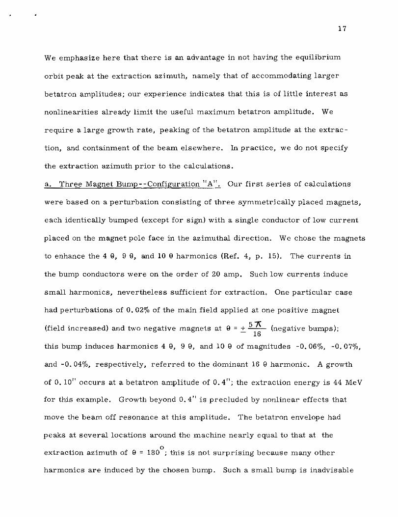
We emphasize here that there is an advantage in not having the equilibrium
orbit peak at the extraction azimuth, namely that of accommodating larger
betatron amplitudes; our experience indicates that this is of little interest as
nonlinearities already limit the useful maximum betatron amplitude. We
require a large growth rate, peaking of the betatron amplitude at the extrac
tion, and containment of the beam elsewhere. In practice, we do not specify
the extraction azimuth prior to the calculations.
a. Three Magnet Bump--Configuration "A". Our first series of calculations
were based on a perturbation consisting of three symmetrically placed magnets,
each identically bumped (except for sign) with a single conductor of low current
placed on the magnet pole face in the azimuthal direction. We chose the magnets
to enhance the 4 9, 9 8, and 10 8 harmonics (Ref. 4, p. 15). The currents in
the bump conductors were on the order of 20 amp. Such low currents induce
small harmonics, nevertheless sufficient for extraction. One particular case
had perturbations of 0.02% of the main field applied at one positive magnet
(field increased) and two negative magnets at 9 = + 51\ (negative bumps); - 16
this bump induces harmonics 4 9, 9 8, and 10 9 of magnitudes -0.06%, -0.070/0,
and -0.04%, respectively, referred to the dominant 16 9 harmonic. A growth
of 0.10" occurs at a betatron amplitude of 0.4"; the extraction energy is 44 MeV
for this example. Growth beyond 0.4" is precluded by nonlinear effects that
move the beam off resonance at this amplitude. The betatron envelope had
peaks at several locations around the machine nearly equal to that at the
o extraction azimuth of 9 = 180 ; this is not surprising because many other
harmonics are induced by the chosen bump. Such a small bump is inadvisable

18
because the induced harmonics are less than an order of magnitude greater
than the corresponding harmonics in the unperturbed field.
b. Single Magnet Bump. From a cost and simplicity standpoint, a most
attractive perturbation scheme is one where a single magnet is bumped with
a single conductor. This we did by depressing the field on a positive magnet
by 70 gauss and accepting the resulting harmonics. This bump induces all
harmonics with low harmonics having magnitudes of the order of O. 10/0 of the
16 e harmonic. A growth of O. 10" is achieved at an amplitude of 0.5". Non
linearities move the beam away from the resonance at larger amplitudes.
c. Three-Magnet Bump--Configuration "B". Dr. Hammer has proposed a
three -magnet bump designed to accentuate the 4 e and 9 e harmonics without
increasing the 3 e, 5 e, 11 e, and 13 e harmonics. The field of the magnet at
e ;: 0 is increased by 112 gauss while those at e ;: :!:. 3 '; are perturbed with
an opposing field of 79 gauss; the ratio of the two bump fields is equal to the
ocosine of 135 . With this bump, we obtain a 4 e component of -0.240/0 and a
9 e component of -0.200/0. A maximum growth of 0.35" is obtained at a
(septum) betatron amplitude of 1. 3 11 This amplitude occurs at six locations•
around the machine, but the equilibrium orbit perturbation places the maxi
0 mum radial excursion at e ;: 180 • Extraction with this bump occurs at
38.6 MeV.
Figure 3 is a radial phase-space plot showing closed phase-space
orbits and the growth of the beam envelope. The beam envelope is well approxi
mated by an ellipse until it grows beyond 0.8" in amplitude. The growth rates
from the linear equations agree with those calculated from the exact equations

20 mr
10
RX' 0 'Y
-10 I
-201
Initial Beam Distribution
Contour in Phase Space Followed by Paricles
Beam Distribution during Extraction (~)
b
tRecommended Septum
Amplitude a
~~.~
b'
L 035U
0'
Radial Growth in Two Turns
- (0 -0.5 0
X inches
0.5 1.0
Beam Distribution With Continuous Extroction
Fig.3 .... ~

20
up to this amplitude. Beyond this amplitude, the growth is more rapid than
indicated by the linear equations. However, at an amplitude of 1. 4", the beam
turns over in phase space and grows very little beyond this amplitude. We
obtain the maximum growth of 0.35" by placing the septum at "a" (Fig. 3);
o f 011 b h b "" d" I " the extracted porhon 0 the beam Wl then e t at etween a an a,
clearly very distorted due to nonlinearities. By moving the septum to a
slightly smaller amplitude as indicated by "b", we obtain a high quality
extracted beam 0.30" wide. This latter choice of septum location yields a
beam that will be much more manageable at little expense in extraction
efficiency. The radial emittance is of the order of 1% of the radial phase
area of the beam prior to resonant growth. Calculations show that particles
with smaller initial amplitudes grow to occupy the same region of phase space
at the extraction amplitude. We would expect to extract 97% of the beam with a
0.01" thick septum, assuming perfect septum alignment.
Linear vertical motion was calculated about that radial trajectory having
the largest betatron amplitude. The amplitude of vertical oscillations was
observed to approximately double by the time the particle was extracted. The
investigation would not show coupling effects involving powers of z and z I
higher than quadratic in the Hamiltonian.
d. High-Gradient Three-Magnet Bump. We investigated a bump identical in
every respect to that described above except for a gradient ten times as large
(an = 0.2"); the magnitudes of the bump fields were not changed. As mentioned
in Section B. 1 above, we expect a much larger growth rate and much larger
nonlinear effects with this bump. A maximum growth of 0.89" over two turns
is obtained. If we insist upon a high quality extracted beam (little distortion),

21
then we are limited to a growth of 0.6". The nonlinearities are not harmful
up to this point; however. there is virtually no agreement between the growths
calculated from the linear equations and those observed using the exact equa
tions. Even at small amplitudes. the beam envelope in phase space is badly
distorted from the initial elliptical shape.
C. Pulsed Extraction Calculations
A number of bump shapes were investigated for a pulsed extraction
system. We assume the initial existence of a stacked beam in an unperturbed
field. The bump is then turned on slowly over approximately 20 turns of the
beam. In each case. the beam was observed to be extracted very rapidly. well
before the bump has been brought to full amplitude.
The steep-gradient three-magnet bump described in the last section
proved to be quite undesirable for the pulsed extraction system. Large beam
growth occurred in a few turns. but no phase lock-in was observed. This lack
of phase lock -in demonstrates that the betatron motion is not dominated by the
increasing exponential component; the nonlinear terms clearly determine the
character of the oscillations.
Using a pulsed extraction system. we are released from the limitation
that the perturbation applied not affect the motion inside the extraction region.
Most of the observed nonlinearities can be eliminated by using a pure gradient
bump to replace that with the radial dependence illustrated in Fig. 2. We
investigated a number of configurations consisting of gradient bumps only.
One of these was a single gradient bump for which ~ ~~ = 1.0 inch-1; this
bump was turned on smoothly over a duration of 20 turns of the circulating
beam. The phase-space profile of the beam is plotted in Fig. 4 at the 2nd.

20
mr
10 T2thfu", l ..th tv",
RX' 0 "Y
-10�
-20�
-1.0 o X inches
Resonant Beam Growth With Single Magnet Pulsed Bump
1.0
N tv
ShoWD 22 V20
Downstream
From Bump
Fig."
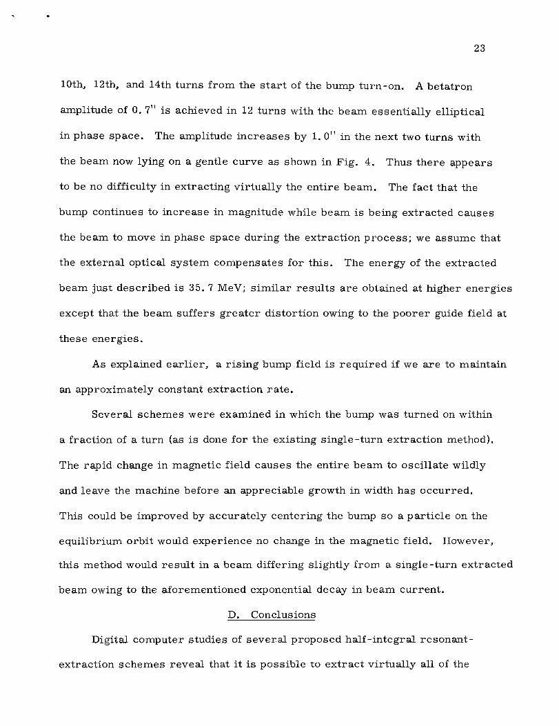
23�
10th, 12th, and 14th turns from the start of the bump turn-on. A betatron
amplitude of O. 7" is achieved in 12 turns with the beam essentially elliptical
in phase space. The amplitude increases by 1. 0" in the next two turns with
the beam now lying on a gentle curve as shown in Fig. 4. Thus there appears
to be no difficulty in extracting virtually the entire beam. The fact that the
bump continues to increase in magnitude while beam is being extracted causes
the beam to move in phase space during the extraction process; we assume that
the external optical system compensates for this. The energy of the extracted
beam just described is 35. 7 MeV; similar results are obtained at higher energies
except that the beam suffers greater distortion owing to the poorer guide field at
these energies.
As explained earlier, a rising bump field is required if we are to maintain
an approximately constant extraction rate.
Several schemes were examined in which the bump was turned on within
a fraction of a turn (as is done for the existing single-turn extraction method).
The rapid change in magnetic field causes the entire beam to oscillate wildly
and leave the machine before an appreciable growth in width has occurred.
This could be improved by accurately centering the bump so a particle on the
equilibrium orbit would experience no change in the magnetic field. However,
this method would result in a beam differing slightly from a single -turn extracted
beam owing to the aforementioned exponential decay in beam current.
D. Conclusions
Digital computer studies of several proposed half-integral resonant
extraction schemes reveal that it is possible to extract virtually all of the

24
beam with only a very small portion striking the septum. Both the continuous
extraction and pulsed extraction systems can be designed to yield an external
beam of high optical quality with a very small emittance. In both systems, a
septum location that results in a beam of low distortion is to be preferred to
the location yielding the minimum beam loss on the septum. The perturbations
required to extract the beam are provided by coils of simple construction.
Control of extraction rate is provided by a programmed rate of acceleration
in the continuous system and by a programmed bump rise in the pulsed system;
a reasonably uniform extraction rate over a large number of turns is desirable
in either case. With the pulsed system, an external array of lenses must be
programmed to compensate for the change in the apparent source of the extracted
beam during the extraction interval. The perturbations should approximate a
pure gradient bump as nearly as possible, consistent with other restrictions,
including the requirement for an adequate growth rate. We believe that the
half-integral resonant extraction system is preferable to those depending
upon higher order resonances on grounds 'of simplicity in construction and
the minimal perturbation field magnitudes required.
REFERENCES
1.� S. C. Snowdon, "Study of a 500 MeV High Intensity Injector", MURA
Report No. 700, September 8, 1964 (unpublished).
E.� M. Rowe, Addendum to MURA-700.
2.� E. M. Rowe, "On the Suitability of the 500 MeV FFAG Synchrotron as an
Injector for the AGS and ZGS", MURA Report No. 701, September 25, 1964
(unpublished). Also E. M. Rowe, Addendum to MURA-700.
3.� C. L. Hammer and L. Jackson Laslett, "Resonant Beam Extraction from
an AG Synchrotron, II Rev. Sci. Instr. 32, 144 (1961).
4.� Werner William Shoultz and C. L. Hammer, "Resonant Beam Extraction
in Fixed Field Alternating Gradient Accelerators, " MURA Report No. 666,
January 2, 1963 (unpublished).
5.� M. M. Gordon, T. A. Welton, T. I. Arnette, and H. C. Owens, "An IBM
704 Code for Determining Equilibrium Orbits and Properties of Small-
Amplitude Oscillations in Cyclotron Fields", Oak Ridge National Laboratory
Laboratory Report ORNL 59-11-2 (Oak Ridge, Tenn.) November 17, 1959
(unpublished).
6.� H. C. Owens and T. A. Welton, "An IBM-704 Code for Studying Particle
Orbits in Cyclotron Fields", Oak Ridge National Laboratory Report ORNL
59-11-3 (Oak Ridge, Tenn.) November 2, 1959 (unpublished).
7.� P. F. Meads, Jr., "II. Ion Optical Design of High Quality Extracted
Synchrotron Beams with Application to the Bevatron", Lawrence Radiation
Laboratory (Berkeley) Report UCRL-10807, May 1963 (unpublished).
8.� P. F. Meads, Jr., "Floating Point Runge-Kutta MURKY7", MURA. Report No. 704, September 10, 1964 (unpublished).
9.� E. D. Courant and H. S. Snyder, "Theory of the Alternating-Gradient�
Synchrotron, " Annals of Physics~, 1 (1958).�
10.� J. Van Bladel, "Magnetic Fields for Extractor Magnet", MURA TN -438,
October 18, 1963 (unpublished).
11.� S. C. Snowdon, "DC Extractor Magnet Field Perturbation Bump'"
MURA TN-516, November 10, 1964 (unpublished).


