
MicroCamp : ATmega8 Activity Kit Manual ��63
This chapter focus learning the applications of the MICROCAMP microcontroller.
The building of a robot integrates knowledge and technology which includes electronics,
programming, mechanical movements, and thinking process. The Microcamp Activity kit
supports this concept. This kit includes all parts for building a simple mobile robot. Users
can learn about programming and how to apply the microcontroller aspects via robotic
activities.
The Mobile robot in MICROCAMP has 2 DC Motor gearboxes for moving and 4
sensors for detecting external values. These are 2 touch sensors and 2 Infrared Reflector
Line tracking sensors for use in black and white line following.
48:1 DC motorgearbox x 2
Circle base plateBox holder x 1
Wheel andTire set x 2
Plastic spacer set x 1 Nut and Screw set x 1
Infrared reflector x 22mm. Self-tappingscrew x2
25mm. metalspacer x 2
Ploastic joiners (Straight, Right angleand Obtuse)
Swithc module x 2
MicroCamp board
Part list
Chapter 7Building robot with
MicroCamp kit
64���MicroCamp : ATmega8 Activity Kit Manual
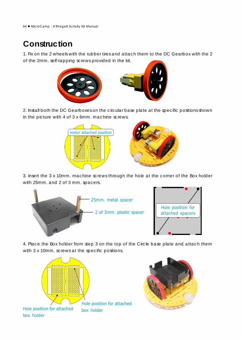
Construction1. Fix on the 2 wheels with the rubber tires and attach them to the DC Gearbox with the 2
of the 2mm. self-tapping screws provided in the kit.
���������������
���������������������
2. Install both the DC Gearboxes on the circular base plate at the specific positions shown
in the picture with 4 of 3 x 6mm. machine screws.
3. Insert the 3 x 10mm. machine screws through the hole at the corner of the Box holder
with 25mm. and 2 of 3 mm. spacers.
4. Place the Box holder from step 3 on the top of the Circle base plate and attach them
with 3 x 10mm. screws at the specific positions.
���� �����������������
�������������� ���������
��������
�������������� ���������
��������
���� �������� ��
��������� ����

MicroCamp : ATmega8 Activity Kit Manual ��65
5. Insert a 3x15mm. machine screw through the Infrared Reflector sensor, followed by 2 of
the 3mm. spacer. Do on both sides for this.
6. Attach both the Infrared Reflector structures from step 5 at the suitable holes at the
bottom and front of the robot base. Tighten with a 3mm. nut.
7. Observe the distance from the floor to the sensors. The suitable distance is 3 to 5 mm.
8. Place MicroCamp board on the box holder. Connect sensor cables and motor cables
following the diagrams shown. (P0 for Right sensor and P1 for Left sensor).
��������� ����
������������������� ��
�������������� ������������� � ���������� ����
��������������������
���
���
����
����
���� � ���������� ��� � ���������� ���� �����������
�� ������ �����
!������� �����

66���MicroCamp : ATmega8 Activity Kit Manual
9. Attach the Straight joiner with robot base at front-right side by 3 x 10mm. machine screw
and 3mm. nut. Attach 2 pieces.
10. Connect the Obtuse joiner at the end of Straight joiner. Attach the right angle joiner
with Switch module by 3 x 10mm. machine screw and 3mm. nut. Make 2 sets. Bring these
structures to connect at the end of the Obtuse joiner. Connect 2 sides.
11. Connect the Left Switch module cable to the P2 (PC2) connector and the Right Switch
module cable to the P3 (PC3) connector. Put 4 AA batteries into battery holder at the
back of MicroCamp board. The MicroCamp robot is ready for programming now.

MicroCamp : ATmega8 Activity Kit Manual ��67
Learning about the Switch circuit
"����������������#��������������� �$�����������������
��������%��
����
���
�
�
�
�� ��
���
����
��
&�����
��������
&� ��� ��������
More information of Infrared Reflector
��� � ���������� ����
&� ��� ��������
���
��������
���
�
��
��
"������ ������������ ��� �#��� ��������� ������������� ���������� ������ � ��� � ������
��������� ������� � ���!'������������� ��� � ���� ����������# ������(����)� ����� ���
����� ����*������ �������� ��� � ��� � ���������� ��� � ��� � ��� �� ����*��+�����,-"��� ����
�����*�����*��� ����������# ����������������������� ����*����� � ���� ��+������� ���
� ��� �� �# ���� ���� �� �# �� ���������)� ����� � ������� ��� ���� �������.� ��� ���� � ��
����*�������������# ��*� ������� ��� ����������������������� ����������/&��� �"$�"�000
�������#�������������������0���1�������������� 2�
"�� ��� �+�0���1��3�����������# ������ ����,-"� �� ����+����� ���������� �����������
������������������
( ��� ����������� �#������������# �����
���������������������� ����������������������������������
������������������� ���������������������������������� ������!"#��������� �
&������������������� �*������ �#�+������������ ������������� �������#������������

68���MicroCamp : ATmega8 Activity Kit Manual
#include <in_out.h>#include <sleep.h>#include <motor.h> // Motor driver libraryvoid main(){
while(1) // Endless loop{
forward(100); // Move the robot forward.sleep(1000); // Delays 1 second.backward(100); // Move the robot backward.sleep(1000); // Delays 1 second.
}}
�������� ����� ����������� ����� ������� �� ����������������� ������ � ��
����� ��
Activity 1Basic movement of MicroCamp robot
Activity 1-1 Forward and Backward movementA1.1 Open the AVR Studio to create the new project and write the C program following
the Listing A1-1. Build this project.
A1.2 Connect the PX-400 programmer to the MicroCamp board on The MicroCamp robot
at the In-System Prog. connector. Turn-on the Robot. Downlaod the HEX code to the robot.
A1.3 Turn-off power and Remove the ISP cable.
A1.4 Make sure the robot is on a flat surface. Turn-on the power and observe the operation.
The MicroCamp robot moves forward. See both LED motor indicators light in green
color. After 1 second, both indicators change color to red and the robot moves backward.
If this is incorrect you will need to re-connect the motor cable to its opposite port /
polarity. Do this until your robot moves correctly. Once its done, Use this motor port
configuration for all your programming activities from now on. The robot will move forward
and backward continually until you turn off its power.

MicroCamp : ATmega8 Activity Kit Manual ��69
#include <in_out.h>#include <sleep.h>#include <motor.h>void main(){
while(1){
while((in_d(2)==1)); // Loop for checking SW1 pressedmotor(1,100); // Apply full power for Motor 1motor(2,30); // Apply 30% power for Motor 2while((in_d(3)==1)); // Loop for checking if SW2 pressedmotor_off(); // Stop all motors.
}}
������������� ���������������������������������� ������ ����� ����������
Program description
In Listing A1-2, the forward and backward com--mands are not used for driving the robot. The MOTORfunction is used instead. This function can control bothmotor outputs separately. This means that you can controlboth the motor’s speed differently.
When both speeds are not equal, the robot willmove towards the direction where the motor is of a lowerspeed. If the speed difference is great, the MicroCamprobot will move in circles.
The While command is used in this program. If SW1at PD2 port is being pressed, the LOGIC value of “O” isreturned. The first conditional loop is false. It thencontinues with the second conditional loop. If SW2 at PD3port is press, the Program will stop both motors. The Robotwill stop its movement.
Activity 1-2 Circle-shape movement controlA1.5 Create a new project file and write the following C Codes shown in A1-2.
A1.6 Connect the PX-400 programmer to the MicroCamp board on The MicroCamp robot
at the In-System Prog. connector. Turn-on the Robot. Downlaod the HEX code to the robot.
A1.7 Turn-off power and Remove the ISP cable.
A1.8 Make sure the robot is on a flat surface. Turn-on the power and observe the robot.
The robot will be activated when you press SW1 and move in circles continually
until you press the SW2 to stop the robot movement.

70���MicroCamp : ATmega8 Activity Kit Manual
#include <in_out.h>#include <sleep.h>#include <motor.h>void main(){
while(1) // Looping{
if (in_d(2)==0) // Check SW1 pressing{
while(1){
forward(100); // Move forward with full speed 0.9 secondsleep(900);s_right(50); // Turn right with 50% speed 0.3 secondsleep(300);
}}if (in_d(3)==0) // Check SW2 pressing{
while(1){
forward(100); // Move forward with full speed 0.9 secondsleep(900);s_left(50); // Turn left with 50% speed 0.3 secondsleep(300);
}}
}}
��������� ��� ������������������ � ���� � ����������� �����������������
���������
���� ������� ���
����� ������
���������
���� ������� ���
����� �� ��
Activity 1-3 Square-shape movement controlA1.9 Create a new project file and write the following C Codes shown in A1-3. Connect
the PX-400 programmer box to the MicroCamp board on The MicroCamp robot at the In-
System Prog. connector. Turn-on the Robot. Downlaod the HEX code to the robot.
A1.10 Turn-off power and Remove the ISP cable. Make sure the robot is on a flat surface.
Turn-on the power and observe the robot.
The robot will be activated if SW1 or SW2 is being pressed. If you Press SW1, the
robot will move forward and turn left continually, making a square. If you press SW2, the
operation is vice versa.

MicroCamp : ATmega8 Activity Kit Manual ��71
Activity 2Object detection with Collision
Activity 2-1 Simple collision detectionThis activity is program the robot to detect the collision of both switches at the front
of the MicroCamp robot. After a collision is encountered, the robot will move backward
and change the its direction of movement.
A2.1 Create a new project file and write the following C Codes shown in A1-4. Build this
project.
A2.2 Connect the PX-400 programmer box to the MicroCamp board on The MicroCamp
robot at the In-System Prog. connector. Turn-on the Robot.
A2.3 Download the HEX code to the robot.
A2.4 Turn-off power and Remove the ISP cable.
A2.6 Prepare the demonstration area by placing and securing boxes or objects on the
surface.
A2.7 Bring the robot into the demonstration area .Turn-on the power and observe the
robot. The MicroCamp robot will read both switch status from PD2 and PC3 port. If any
switch is pressed or touches some object, the result is logic “0”.
In a normal operation, the robot will move forward continually.
If the Left Switch module touches any object, the robot will move backward and
change its moving direction to its right to avoid the object.
If the Right Switch module touches any object, the robot will move backward and
change its moving direction to its left to avoid the object.
72���MicroCamp : ATmega8 Activity Kit Manual
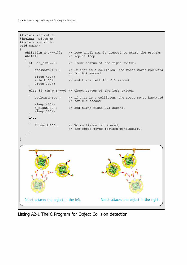
������������� ���������������!�" �������������# � �����
#include <in_out.h>#include <sleep.h>#include <motor.h>void main(){
while((in_d(2)==1)); // Loop until SW1 is pressed to start the program.while(1) // Repeat loop{
if (in_c(2)==0) // Check status of the right switch.{
backward(100); // If ther is a collision, the robot moves backward// for 0.4 second
sleep(400);s_left(50); // and turns left for 0.3 second.sleep(300);
}else if (in_c(3)==0) // Check status of the left switch.{
backward(100); // If ther is a collision, the robot moves backward// for 0.4 second
sleep(400);s_right(50); // and turns right 0.3 second.sleep(300);
}else{
forward(100); // No collision is deteced,// the robot moves forward continually.
}}
}
������������������������� ������� �� � ������������������������� ������������
MicroCamp : ATmega8 Activity Kit Manual ��73
#include <in_out.h>#include <sleep.h>#include <motor.h>#include <sound.h> // Sound libraryvoid main(){
unsigned char cnt_=0; // Declare variable for counting the number of// collision both left and right.
while((in_d(2)==1)); // Wait for SW1 is pressed to start operationsound(3000,100); // Beep at once
while(1) // Looping{
if (in_c(2)==0) // Check the right-side collision{
if ((cnt_%2)==0) // Check the counter as even number or not.// If yes, means the previous collision is left-// side collision.
{cnt_++;} // Increment the counterelse // If not left-side collision,{cnt_=0;} // clear the counterbackward(100); // Move backward 0.4 secondsleep(400); //s_left(50); // Turn leftif (cnt_>5) // Check the counter over 5 or not.{
sleep(700); // If over, turn left more 0.7 second.sound(3000,100); // Drive sound to piezo speaker
cnt_=0; // Clear counter}
��������������� ������������������������������� ��������������������$����
��������� %������$ ��&
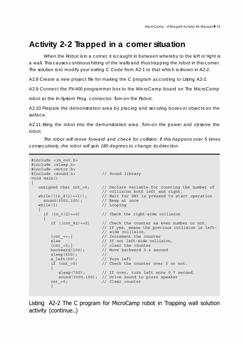
Activity 2-2 Trapped in a corner situationWhen the Robot is in a corner, it is caught in between whereby to the left or right is
a wall. This causes continous hitting of the walls and thus trapping the robot in this corner.
The solution is to modify your exiting C Code from A2-1 to that which is shown in A2-2.
A2.8 Create a new project file for making the C program according to Listing A2-2.
A2.9 Connect the PX-400 programmer box to the MicroCamp board on The MicroCamp
robot at the In-System Prog. connector. Turn-on the Robot.
A2.10 Prepare the demonstration area by placing and securing boxes or objects on the
surface.
A2.11 Bring the robot into the demonstration area .Turn-on the power and observe the
robot.
The robot will move forward and check for collision. If this happens over 5 times
consecutively, the robot will spin 180 degrees to change its direction.

74���MicroCamp : ATmega8 Activity Kit Manual
else // If counter is less than 5,{ sleep(300);} // Set time value for turning to 0.3 second.
}else if (in_c(3)==0) // Check the leftt-side collision{
if ((cnt_%2)==1) // Counter is odd number or not.// If yes, the previous collision is right-side.
{cnt_++;} // Increment counterelse{cnt_=0;} // If not, clear counterbackward(100); // Robot move backward for 0.4 secondsleep(400); //s_right(50); // Turn right for 0.3 secondsleep(300); //
}else // If not collision, move forward.{forward(100);}
}}
��������������� ������������������������������� ��������������������$����
���������%�����&
MicroCamp : ATmega8 Activity Kit Manual ��75
From the 2 first activities, these show how to read the digtal input signal and to get
the data to control robot movement. In this activity, there will be many activities about
reading analog inputs and processing the data to detect black and white areas. It also
detects Black and white line to control the robot to move along the line with conditions.
The MicroCamp robot has 5 analog inputs that directly connects to the PC0 to
PC4 of ATmega8 microcontroller. This microcontroller contains the 10-bit analog to digital
converter (ADC) module. The digital conversion data is 0 to 1023 in decimal number format.
C programming for this activity require a library file. It is the analog.h file. Functions
in this library will define relate the input port to the analog input and reads data from ADC
module to store in its memory. The resulting data range is 0 to 1023 in decimals or 0000H to
03FFH in hexadecimals.
The important devices in this activity is the 2 Infrared Reflector modules. They are
installed at the bottom of the robot base. They are used to detect the surface’s color
(black and white) including the white and black line. The Line tracking robot activity is the
classic activity. It shows the basic robot’s programming performance.
Activity 3-1 Testing black and white areaThe MicroCamp robot is attached with 2 of Infrared Reflector module at bottom of
the robot base ready. Thus, this activity will only dwell on programming.
Before develop the robot to track the line, developers must program the robot to
detect the difference between black and white color surface.
(A) White surface testingThis sub-activity presents how to detect the white surface. The Listing A3-1 is C program
for testing Infrared Reflector operation. After execution, the program will wait for SW1 or
SW2 pressing.
If press SW1 : select to read data from P0 or PC0 analog port
If press SW2 : select to read data from P1 or PC1 analog port
After pressing the switch, the program will read data at the port pin continuously
and will not switch to read another sensor unless the RESET button is pressed. Developers
must press both switches to get the sensor’s data.
Activity 3Line tracking robot

76���MicroCamp : ATmega8 Activity Kit Manual
#include <in_out.h>#include <sound.h>#include <analog.h> // Analog reading libraryvoid main(){
while(1) // Loop for waiting the key selection to// read P0 or P1
{if((in_d(2)==0)) // Check SW1 pressing{
while(1) // Repeat this loop{
if (analog(0)>350) // Read the value from P0 and check the// white surface.
{sound(3000,100); // If the white surface is deteced,
// drive the sound to speaker.}
}}if((in_d(3)==0)) // Check SW2 pressing{
while(1) // Repeat this loop{
if (analog(1)>350) // Read the value from P1 and check the// white surface.
{sound(3000,100); // If the white surface is deteced,
// drive the sound to speaker.}
}}
}}
��������� ��� ����������������������������������'��� ��$���� �� ��������������
Compare the sensor’s data with the reference data; 350.
If data values are more than 350, the color that is detected is white color.
If data values are less than 350, the color that is detected is black color.
After detect the white surface ready, program will send the sound signal to piezo
speaker.
A3.1 Make the black & white testing sheet. The white surface area is 30 x 30 cm. and
black surface is 30 x 30cm.
A3.2 Create the new project file and make the C program following the Listing A3-1. Build
this project file.
A3.3 Connect the PX-400 programmer box with MicroCamp robot and download the HEX
code to the robot.

MicroCamp : ATmega8 Activity Kit Manual ��77
A3.4 Place the robot on the black surface first. Turn on the power and press SW1 switch.
The Robot does not move.
A3.5 Place the robot on the white surface and try to roll the robot.
The robot produces sounds when its on a white surface.
A3.6 Press the RESET switch. Place the robot on the black surface again. Press switch SW2
to test the operation of the Infrared Reflector at P1 port. Observe the robot’s operation.
After press SW2, robot will get data from sensors at P1 port and compare the
reference value ; 350. If the reading value more than 350, means the robot detects the
white area. It send sound signal to drive a piezo speaker. From step A3.6, robot detects
the black surface then do not work anything.
A3.7 Place the robot on the white surface and try to roll the robot.
Robot drives sound always above the white surface.
A3.8 If the robot cannot drive the signal when placed on the white surface in testing. The
solution is
(1) Decrease the reference value from 350 but not lower 100
(2) Adjust the sensor position to decrease the distance from the floor.
A3.9 The Listing A3-2 is C program for testing the black surface. Developers can test with
this program to check the black surface detection of robot to make sure the robot can
detect white and black surface well. The procedure is same in step A3.4 to A3.8. But the
decision criteria will change from higher 350 to lower 350 instead.

78���MicroCamp : ATmega8 Activity Kit Manual
#include <in_out.h>#include <sound.h>#include <analog.h> // Analog reading libraryvoid main(){
while(1) // Loop for waiting key selection to readP0 or P1
{if((in_d(2)==0)) // Check SW1 pressing{
while(1) // Repeat this loop{
if (analog(0)<350) // Read the value from P0 and check the// black surface.
{sound(3000,100); // If the black surface is detected,
// drive the sound to speaker.}
}}if((in_d(3)==0)) // Check SW2 pressing{
while(1) // Repeat the loop{
if (analog(1)<350) // Read the value from P1 and check the// black surface.
{sound(3000,100); // If the black surface is deteced,
// drive the sound to speaker.}
}}
}}
��������� ���� ��������������������������������� �(��� �)���(��$���� ���������

MicroCamp : ATmega8 Activity Kit Manual ��79
��������
!���� ��������"���������
���������
#� �������������������������
���������
��������������������� ���� ����
Activity 3-2 Robot moves along the black line������������� ����� ���������������������������
(1) Both sensors read values that are white : The robot will move forward.
Thus, this program is written so that the robot moves forward normally.
(2) The left sensor reads black while the right sensor reads white : This occurs
when the robot is slightly turned to the right. Thus, the program is written for the robot to
move back left to resume its normal path.
(3) The left sensor read white while the right sensor reads black : This occurs
when the robot is slightly turned to the left. Thus, the program is written for the robot to
move back to the right to resume its normal path.
From all scenarioes, can make the C program in the Listing A3-3.
A3.10 Make the simple black line sheet. It has not the cross line. Most area is white color.
Size of sheet can determine suitable for your robot.
A3.11 Create the new project file and make the C program following the Listing A3-3. Build
this project file.
A3.12 Connect the PX-400 programmer box with MicroCamp robot and download the
HEX code to the robot. Turn off power and unplug ISP cable from the robot.

80���MicroCamp : ATmega8 Activity Kit Manual
#include <in_out.h>#include <sound.h>#include <analog.h>#include <motor.h> // Motor diver libraryunsigned int AD0=350,AD1=350; // Determine the sensor reference
// value.void main(){
while((in_d(2)==1)); // Wait pressing SW1 to start the// program
while(1){
if((analog(0)>AD0)&&(analog(1)>AD1)) // Both sensor detect the white// surface.
forward(100); // Move forwardif (analog(0)<AD0) // Left sensor detects black line.
s_left(100); // Turn leftif (analog(1)<AD1) // Right sensor detects black line.
s_right(100); // Turn right}
}
��������� ��� ����������� ���� ������������ �� ����������� ������ ������ �
�������� �����(����
A3.13 Place the robot across the black line on the sheet. Turn on power and press SW1
switch.
Robot will move along the black line. It is possible that the robot moves out of the
line. You can improve the precision by editing the program with adjusting the sensor
reference value and adjust to the position of both the Infrared Reflector sensors.

MicroCamp : ATmega8 Activity Kit Manual ��81
Activity 3-3 Line crossing detectionFrom the activity 3-2, you can improve the MicroCamp robot so that it moves along
the black line and detect the junction or line with same 2 sensors. One thing to do is edit
the program.
When the robot moves to line crossing, both sensors will detect black line. You must
add the program for support this scenario. The improved C program is shown in the Listing
A3-4
A3.14 Improve the simple black line sheet from Activity 3-2. Add some cross lines. The number
will depend on your inquiry.
A3.15 Create the new project file and make the C program following the Listing A3-4. Build
this project file.
A3.16 Connect the PX-400 programmer box with MicroCamp robot and download the
HEX code to the robot. Turn off power and unplug ISP cable from the robot.
A3.17 Place the robot across the black line on the sheet. Turn on power and press SW1
switch.
Robot will move along the black line. When the robot detects the crossing, it will
brake and drive sound once. When it finds the second crossing, the robot will drive sound
twice and this will increase for the subsequent crossings.
Note : In the motor brake operation, robot will stop and lock the motor’s shaft immediately.
But sometimes, this is not enough. You must program the robot to move backwards for a
short time. This will cause the robot to stop at its position.
82���MicroCamp : ATmega8 Activity Kit Manual
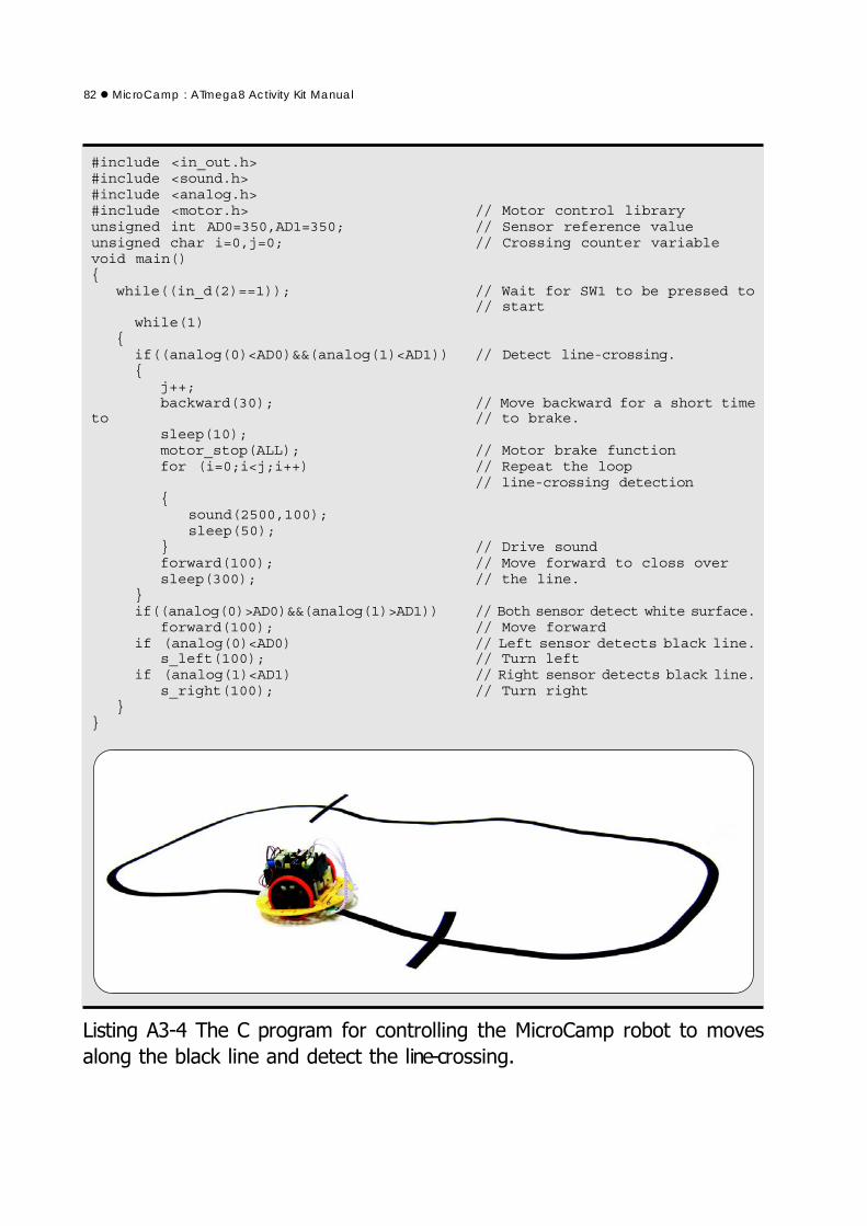
#include <in_out.h>#include <sound.h>#include <analog.h>#include <motor.h> // Motor control libraryunsigned int AD0=350,AD1=350; // Sensor reference valueunsigned char i=0,j=0; // Crossing counter variablevoid main(){
while((in_d(2)==1)); // Wait for SW1 to be pressed to// start
while(1){
if((analog(0)<AD0)&&(analog(1)<AD1)) // Detect line-crossing.{
j++;backward(30); // Move backward for a short time
to // to brake.sleep(10);motor_stop(ALL); // Motor brake functionfor (i=0;i<j;i++) // Repeat the loop
// line-crossing detection{
sound(2500,100);sleep(50);
} // Drive soundforward(100); // Move forward to closs oversleep(300); // the line.
}if((analog(0)>AD0)&&(analog(1)>AD1)) // Both sensor detect white surface.
forward(100); // Move forwardif (analog(0)<AD0) // Left sensor detects black line.
s_left(100); // Turn leftif (analog(1)<AD1) // Right sensor detects black line.
s_right(100); // Turn right}
}
��������� *��� ����������� ���� ������������ �� ����������� ������ ������ �
�������� �����(���� ���#�# � ����� ���� ���������


