Download - MicroLogix Packaged Controllers
MicroLogix Packaged Controllers
Programmable Controller BasicsMemory & Data
We are going to discuss...We are going to discuss...
1. Memory
2. Data
3. Data Files
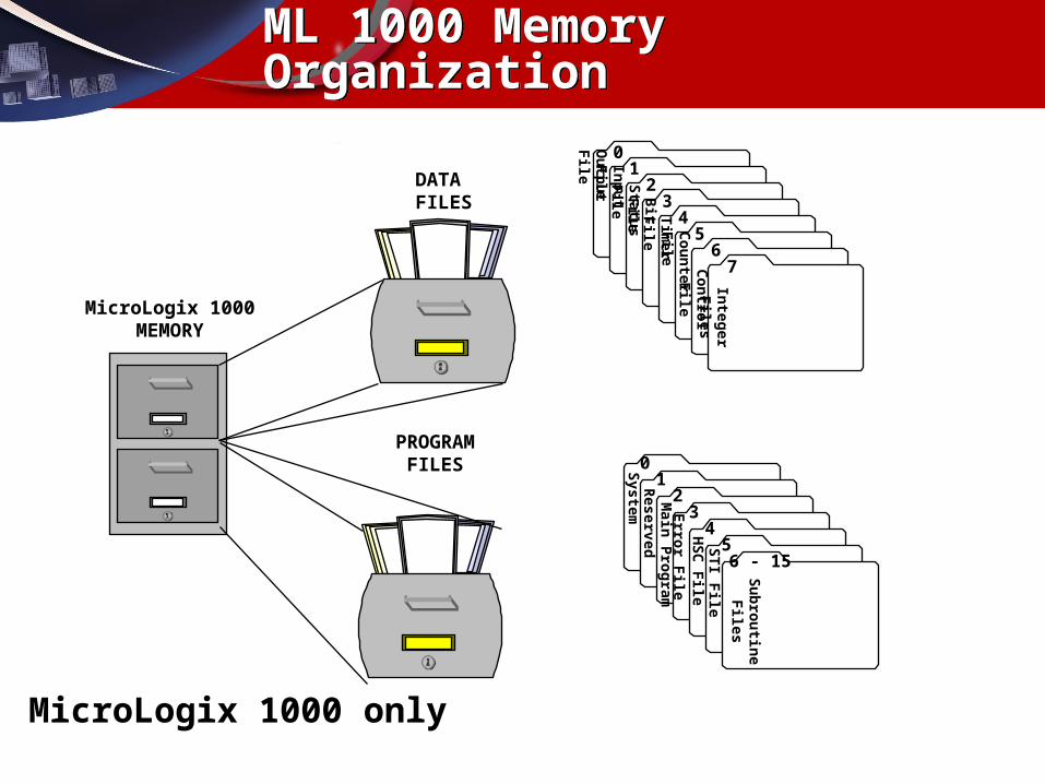
MicroLogix 1000MEMORY
PROGRAMFILES 0
12
34
56 - 15
System
ReservedM
ain P
rog
ramE
rror F
ileH
SC
File
ST
I File
Su
bro
utin
eF
iles
DATAFILES
01
23
45
67
Ou
tpu
t File
Inp
ut F
ileS
tatus F
ileB
it File
Tim
er File
Co
un
ter File
Co
ntro
l File
Integ
er Files
ML 1000 Memory OrganizationML 1000 Memory Organization
MicroLogix 1000 only
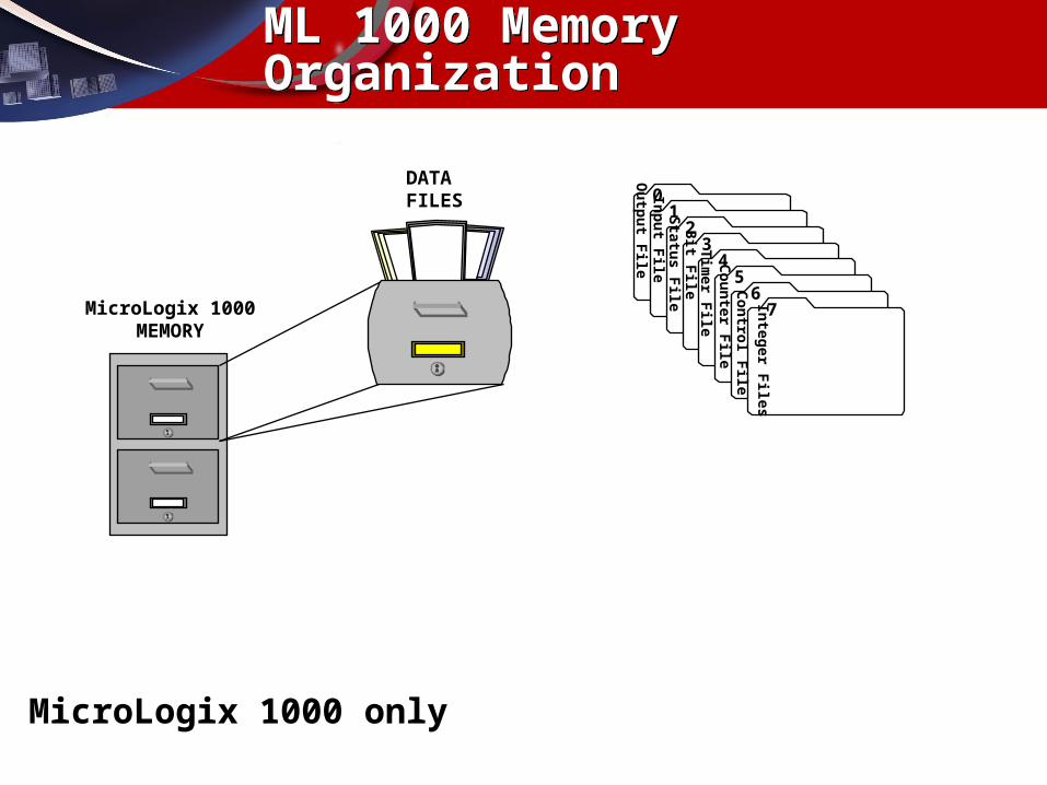
MicroLogix 1000MEMORY
DATAFILES 0
12
34
56
7
Ou
tpu
t File
Inp
ut F
ileS
tatus F
ileB
it File
Tim
er File
Co
un
ter File
Co
ntro
l File
Integ
er Files
ML 1000 Memory OrganizationML 1000 Memory Organization
MicroLogix 1000 only
Memory & DataMemory & Data
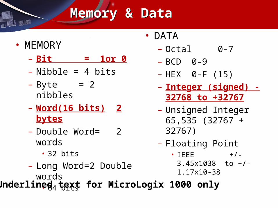
• MEMORY– Bit = 1or 0– Nibble = 4 bits– Byte = 2 nibbles– Word(16 bits) 2 bytes– Double Word= 2 words
• 32 bits
– Long Word=2 Double words• 64 bits
• DATA– Octal 0-7– BCD 0-9– HEX 0-F (15)– Integer (signed) -32768 to
+32767– Unsigned Integer 65,535
(32767 + 32767)– Floating Point
• IEEE +/- 3.45x1038 to +/-1.17x10-38
Underlined text for MicroLogix 1000 only
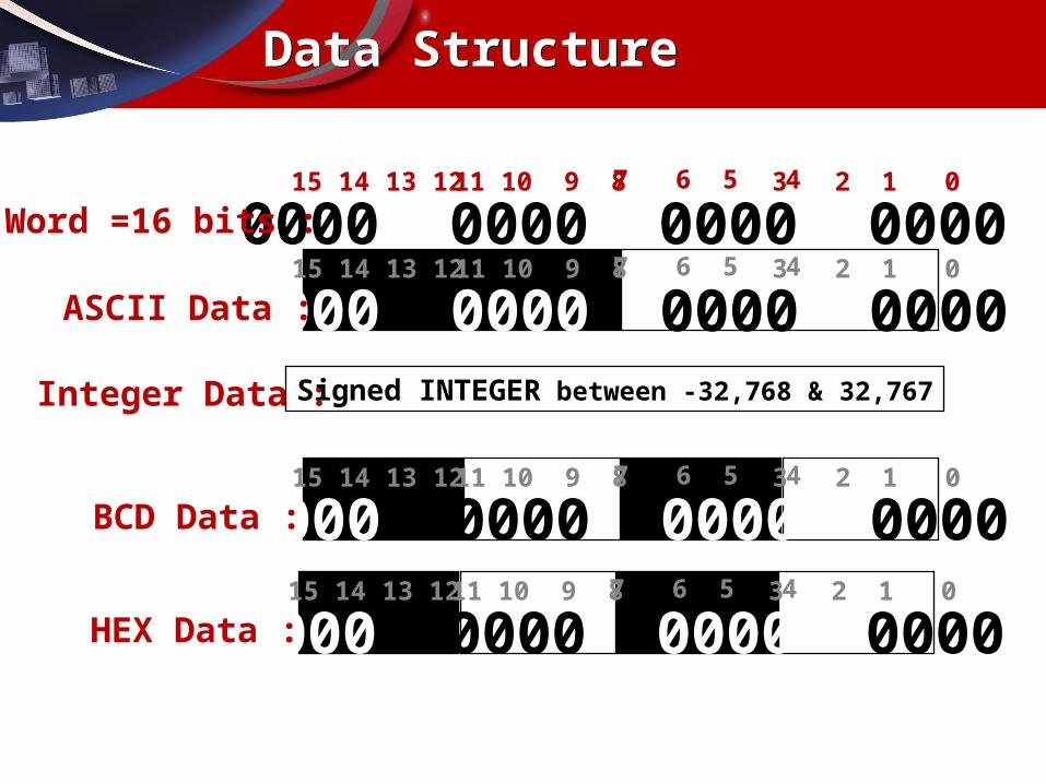
Integer Data : Signed INTEGER between -32,768 & 32,767
0000 0000 0000 000015 14 13 12 11 10 9 8 7 6 5 4 3 2 1 0
Word =16 bits :
0000 0000 0000 000015 14 13 12 11 10 9 8 7 6 5 4 3 2 1 0
ASCII Data :
0000 0000 0000 000015 14 13 12 11 10 9 8 7 6 5 4 3 2 1 0
BCD Data :
0000 0000 0000 000015 14 13 12 11 10 9 8 7 6 5 4 3 2 1 0
HEX Data :
Data StructureData Structure
ASCII
HEX DEC ASCII
HEX DEC ASCII
HEX DEC
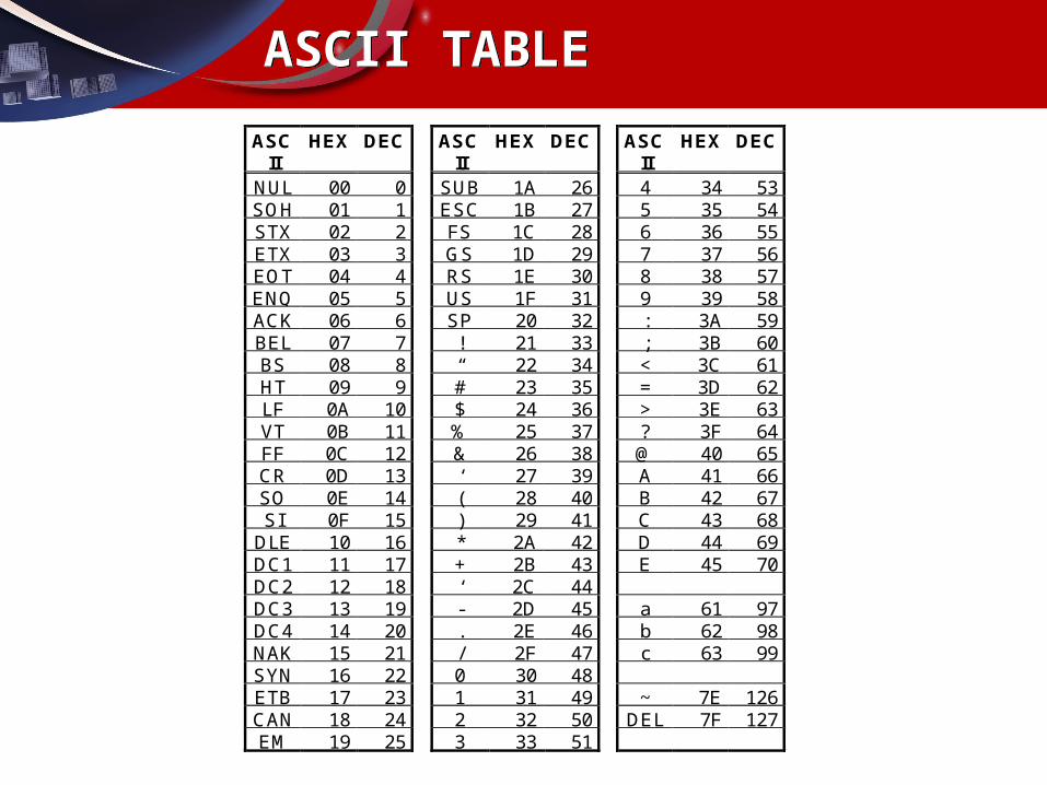
NUL 00 0 SUB 1A 26 4 34 53SOH 01 1 ESC 1B 27 5 35 54STX 02 2 FS 1C 28 6 36 55ETX 03 3 GS 1D 29 7 37 56EOT 04 4 RS 1E 30 8 38 57ENQ 05 5 US 1F 31 9 39 58ACK 06 6 SP 20 32 : 3A 59BEL 07 7 ! 21 33 ; 3B 60BS 08 8 “ 22 34 < 3C 61HT 09 9 # 23 35 = 3D 62LF 0A 10 $ 24 36 > 3E 63VT 0B 11 % 25 37 ? 3F 64FF 0C 12 & 26 38 @ 40 65CR 0D 13 ‘ 27 39 A 41 66SO 0E 14 ( 28 40 B 42 67SI 0F 15 ) 29 41 C 43 68
DLE 10 16 * 2A 42 D 44 69DC1 11 17 + 2B 43 E 45 70DC2 12 18 ‘ 2C 44DC3 13 19 - 2D 45 a 61 97DC4 14 20 . 2E 46 b 62 98NAK 15 21 / 2F 47 c 63 99SYN 16 22 0 30 48ETB 17 23 1 31 49 ~ 7E 126CAN 18 24 2 32 50 DEL 7F 127EM 19 25 3 33 51
ASCII TABLEASCII TABLE
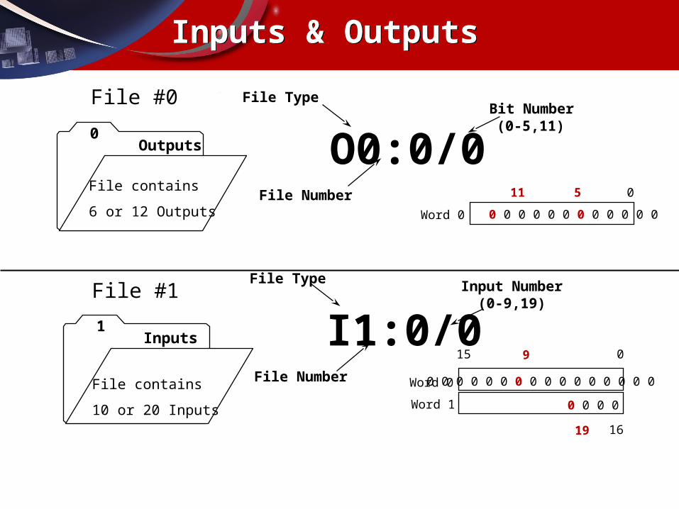
O0:0/0
File Type
File Number
Bit Number(0-5,11)0
Outputs
File contains
6 or 12 Outputs
11 5 0
0 0 0 0 0 0 0 0 0 0 0 0Word 0
15
16
0
Word 0
I1:0/0
File Type
File Number
Input Number(0-9,19)
1Inputs
File contains
10 or 20 Inputs
0 0 0 0 0 0 0 0 0 0 0 0 0 0 0 0
0 0 0 0
File #0
File #1
Inputs & OutputsInputs & Outputs
Word 1
19
9
Status FileStatus File
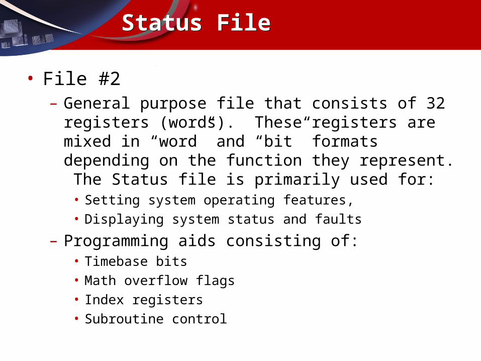
• File #2– General purpose file that consists of 32 registers (words). These
registers are mixed in “word” and “bit” formats depending on the function they represent. The Status file is primarily used for:
• Setting system operating features,• Displaying system status and faults
– Programming aids consisting of:• Timebase bits• Math overflow flags• Index registers• Subroutine control
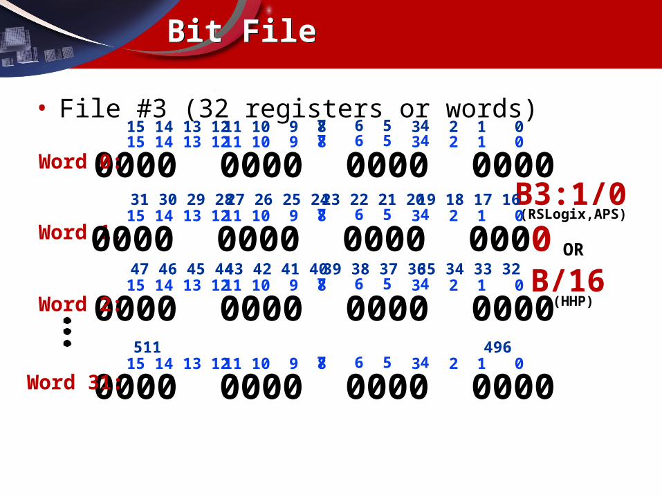
B/16
(RSLogix,APS)
OR
(HHP)
B3:1/00000 0000 0000 000015 14 13 12 11 10 9 8 7 6 5 4 3 2 1 0
Word 0:
Word 1: 0000 0000 0000 000015 14 13 12 11 10 9 8 7 6 5 4 3 2 1 031 30 29 28 27 26 25 24 23 22 21 20 19 18 17 16
0000 0000 0000 000015 14 13 12 11 10 9 8 7 6 5 4 3 2 1 0
Word 2:
47 46 45 44 43 42 41 40 39 38 37 36 35 34 33 32
15 14 13 12 11 10 9 8 7 6 5 4 3 2 1 0
0000 0000 0000 000015 14 13 12 11 10 9 8 7 6 5 4 3 2 1 0
Word 31:
511 496
Bit FileBit File
• File #3 (32 registers or words)
| |I:0.0
0
TimersTimers
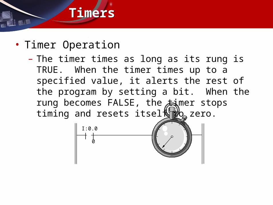
• Timer Operation– The timer times as long as its rung is TRUE. When the timer times
up to a specified value, it alerts the rest of the program by setting a bit. When the rung becomes FALSE, the timer stops timing and resets itself to zero.
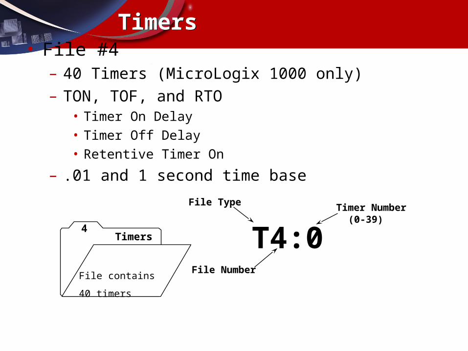
T4:0
File Type
File Number
Timer Number(0-39)
4Timers
File contains
40 timers
TimersTimers• File #4
– 40 Timers (MicroLogix 1000 only)– TON, TOF, and RTO
• Timer On Delay• Timer Off Delay• Retentive Timer On
– .01 and 1 second time base
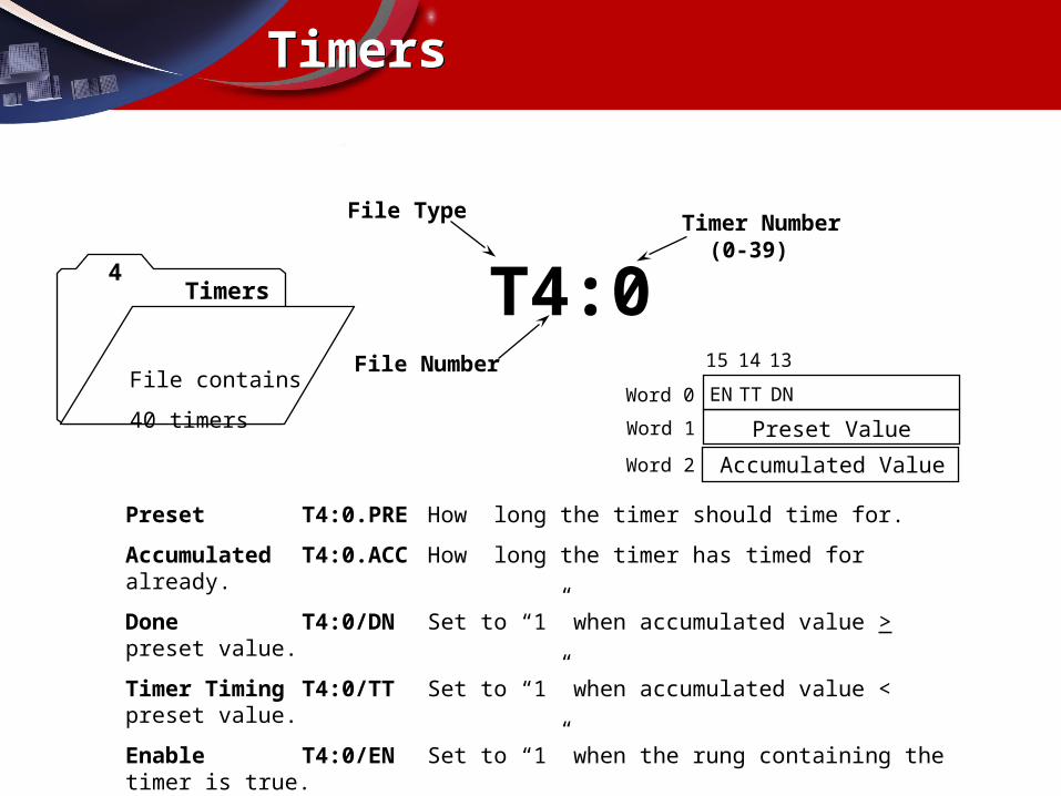
Preset T4:0.PRE How long the timer should time for.
Accumulated T4:0.ACC How long the timer has timed for already.
Done T4:0/DN Set to “1” when accumulated value > preset value.
Timer Timing T4:0/TT Set to “1” when accumulated value < preset value.
Enable T4:0/EN Set to “1” when the rung containing the timer is true.
T4:0
File Type
File Number
Timer Number(0-39)
4Timers
File contains
40 timers Preset Value
Accumulated Value
15 14 13
EN TT DNWord 0
Word 1
Word 2
TimersTimers

TIMER ON DELAYTimer T4:0Time Base 1.0Preset 10Accum 0
TON
Stop Start Motor
]/[ ] [
] [
( )I:0/0I:0/1
M1O:0/3
O:0/3
] [
M1O:0/3
]/[T4:0/DN
(EN)
(DN)
Timer Done
TimersTimers
• The Timer’s “done bit” turns the motor off after a 10 second time delay
| |I:0.0
0
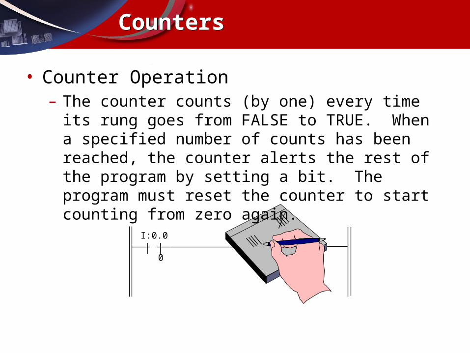
CountersCounters
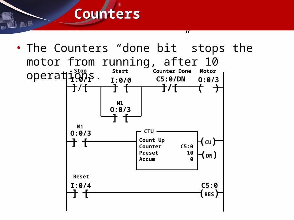
• Counter Operation– The counter counts (by one) every time its rung goes from FALSE
to TRUE. When a specified number of counts has been reached, the counter alerts the rest of the program by setting a bit. The program must reset the counter to start counting from zero again.
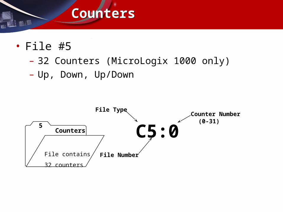
C5:0
File Type
File Number
Counter Number(0-31)
5Counters
File contains
32 counters
CountersCounters
• File #5– 32 Counters (MicroLogix 1000 only)– Up, Down, Up/Down
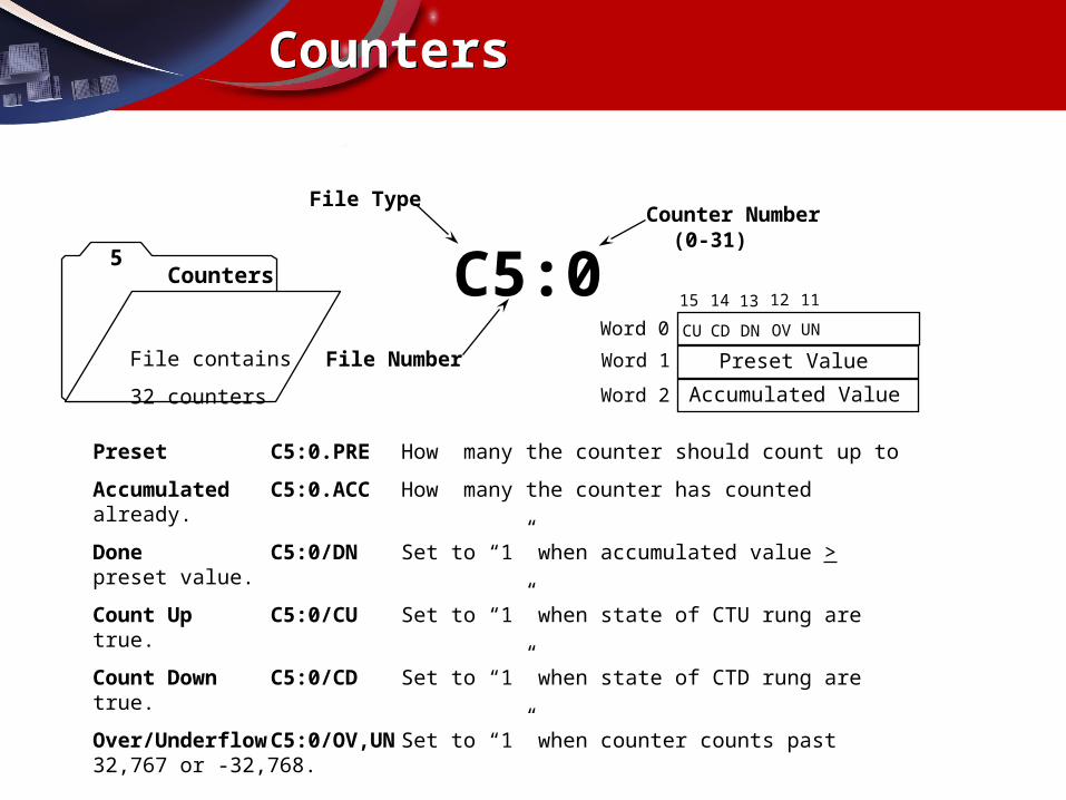
Preset C5:0.PRE How many the counter should count up to
Accumulated C5:0.ACC How many the counter has counted already.
Done C5:0/DN Set to “1” when accumulated value > preset value.
Count Up C5:0/CU Set to “1” when state of CTU rung are true.
Count Down C5:0/CD Set to “1” when state of CTD rung are true.
Over/Underflow C5:0/OV,UN Set to “1” when counter counts past 32,767 or -32,768.
C5:0
File Type
File Number
Counter Number(0-31)
5Counters
File contains
32 counters
Preset Value
Accumulated Value
15 14 13
CU CD DN OV UN
12 11
Word 0
Word 1
Word 2
CountersCounters
Count UpCounter C5:0Preset 10Accum 0
CTU
Stop Motor
]/[
] [
( )
Start
] [I:0/0I:0/1
M1O:0/3
O:0/3
] [
M1O:0/3
]/[C5:0/DN
(CU)
(DN)
Counter Done
Reset
] [I:0/4
(RES)C5:0
CountersCounters
• The Counters “done bit” stops the motor from running, after 10 operations.
ControlControl
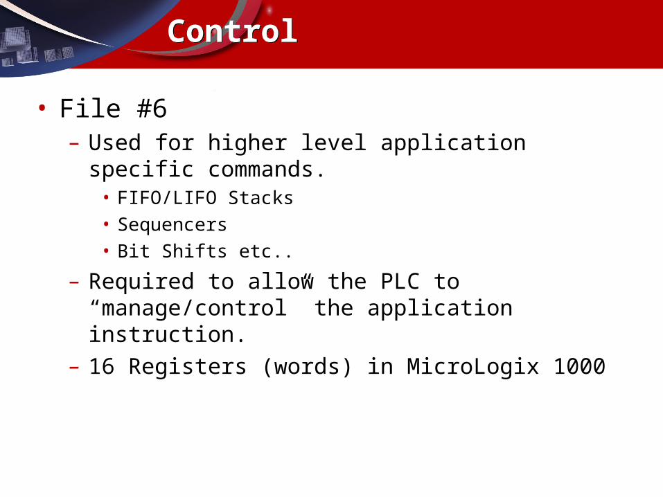
• File #6– Used for higher level application specific commands.
• FIFO/LIFO Stacks• Sequencers• Bit Shifts etc..
– Required to allow the PLC to “manage/control” the application instruction.
– 16 Registers (words) in MicroLogix 1000
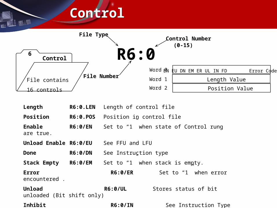
Length R6:0.LEN Length of control file
Position R6:0.POS Position in control file
Enable R6:0/EN Set to “1” when state of Control rung are true.
Unload Enable R6:0/EU See FFU and LFU
Done R6:0/DN See Instruction type
Stack Empty R6:0/EM Set to “1” when stack is empty.
Error R6:0/ER Set to “1” when error encountered .
Unload R6:0/UL Stores status of bit unloaded (Bit shift only)
Inhibit R6:0/IN See Instruction Type
Found R6:0/FD See Sequencer compare instruction (SQC)
R6:0
File Type
File Number
Control Number(0-15)
6Control
File contains
16 controls
Length Value
Position Value
Word 0
Word 1
Word 2
EN EU DN EM ER UL IN FD Error Code
ControlControl
IntegerInteger
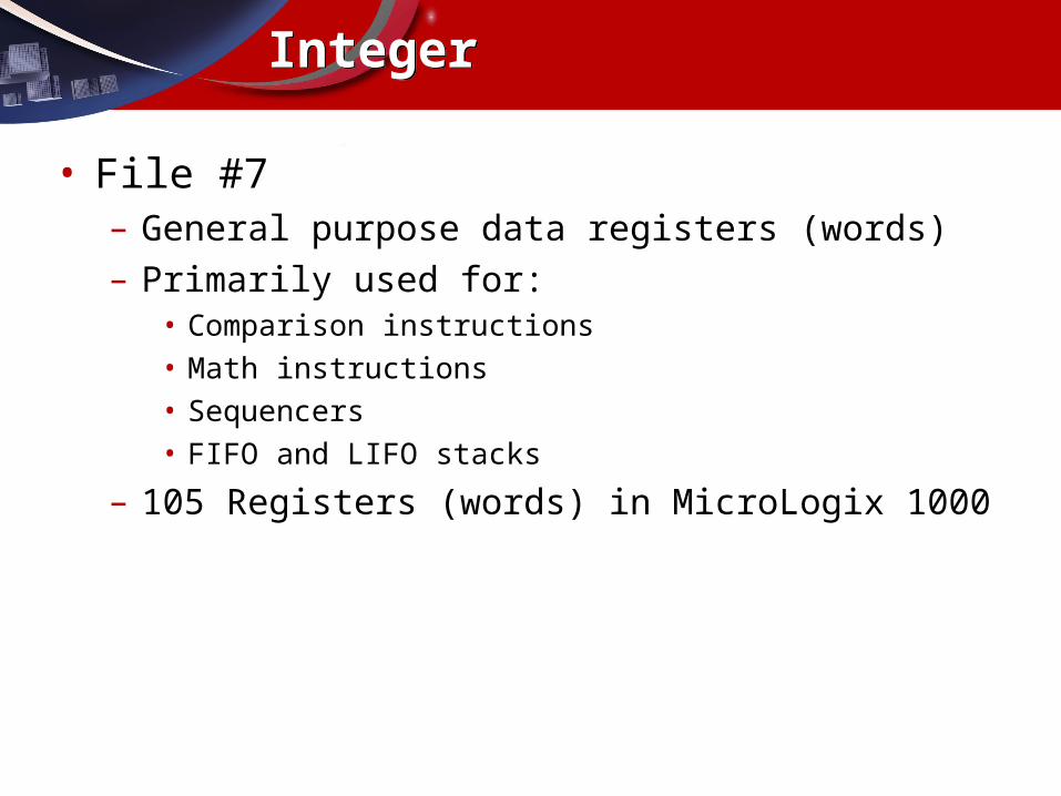
• File #7– General purpose data registers (words)– Primarily used for:
• Comparison instructions• Math instructions• Sequencers• FIFO and LIFO stacks
– 105 Registers (words) in MicroLogix 1000


