
Microsoft Kinect Based Mobile Robot Car
China Project Center E term, 2012
A Major Qualifying Project submitted to the Faculty of WORCESTER POLYTECHNIC
INSTITUTE in partial fulfillment of the requirements for the Degree of Bachelor of Science
Authors
Max Saccoccio, Robotics and Mechanical Engineering, 2013 ([email protected])
Joseph Taleb, Electrical and Computer Engineering, 2013 ([email protected])
Partnered With:
Kang Lutan, Mechanical Engineering ([email protected])
Xie Man, Mechanical Engineering, ([email protected])
Wei Bo, Mechanical Engineering ([email protected])
Wang Li, Mechanical Engineering ([email protected])
Liaison
Zhang Huiping, DEPUSH Technologies Ltd., Wuhan, China
Project Advisors
Professor Lingsong He, HUST Dept. of Mechanical Engineering
Professor Xinmin Huang, WPI Dept. of Electrical and Computer Engineering
Professor Yiming Rong, WPI Dept. of Mechanical Engineering
Professor Stephen Nestinger, WPI Dept. of Mechanical Engineering

ii
Abstract Using Microsoft Robotics Developer Studio and the Parallax Eddie robot platform, a mobile
robot car was developed using the Microsoft Kinect as the primary computer vision sensor to identify
and respond to voice and gesture commands. The project sponsor, Depush Technology of Wuhan, China
has requested a commercially viable educational platform. The end user programs the robot using
Microsoft Visual Programming Language to implement code written in C#.

iii
Acknowledgements
We would like to thank our project advisors, Professor Rong of Worcester Polytechnic Institute,
and Professor He of Huazhong University of Technology, for their help with our project. We would like to
thank them for the input they have provided to our project, especially to our presentation and this
report. Professor Rong supplied valuable suggestions to help us make our presentation the best that it
could be. We would also like to thank them for affording us the opportunity to work with students from
different countries.
We would also like to thank our contact at Depush, Zhang,Huiping, for his support to our
project. Without his constant support on our project, none of what we have achieved could have been
possible. The team is grateful to have had the opportunity to visit Depush Technology and the chance to
see the several different kinds of interesting robots they produce.

iv
Table of Contents
Abstract ......................................................................................................................................................... ii
Acknowledgements ...................................................................................................................................... iii
Table of Figures ............................................................................................................................................ vi
Table of Tables ............................................................................................................................................ vii
Introduction .................................................................................................................................................. 1
Literature Review .......................................................................................................................................... 3
Robot-Human Interaction ......................................................................................................................... 3
Task Completion.................................................................................................................................... 3
Personal Experience .............................................................................................................................. 4
Interaction Experience .......................................................................................................................... 4
Computer Vision ....................................................................................................................................... 5
Kinect Specifications ................................................................................................................................. 6
Robot Platform .......................................................................................................................................... 8
Microsoft Robotics Developer Studio ..................................................................................................... 11
Programming Languages ......................................................................................................................... 12
C# ........................................................................................................................................................ 12
VPL ...................................................................................................................................................... 13
Project Sponsor ....................................................................................................................................... 15
Educational Robotics ............................................................................................................................... 17
Methodology ............................................................................................................................................... 20
Purpose ................................................................................................................................................... 20
Objectives ............................................................................................................................................... 21
Objective 1: Kinect Technology ........................................................................................................... 21
Objective 2: Voice and Gesture Control.............................................................................................. 21
Objective 3: Self-preservation ............................................................................................................ 22
Objective 4: Final Product ................................................................................................................... 22
Project Planning ...................................................................................................................................... 22
Design .......................................................................................................................................................... 24
Follower Service ...................................................................................................................................... 24
Gesture Recognition Service ................................................................................................................... 25

v
Speech Recognition Service .................................................................................................................... 28
Operations .......................................................................................................................................... 29
Initial state properties ......................................................................................................................... 31
Service State ........................................................................................................................................ 32
Obstacle Avoidance Algorithm................................................................................................................ 33
User Interface ......................................................................................................................................... 33
Analysis ....................................................................................................................................................... 37
Final Prototype Evaluation ...................................................................................................................... 37
Kinect as Computer Vision .................................................................................................................. 37
Gesture Recognition Performance...................................................................................................... 38
Speech Recognition Performance ....................................................................................................... 39
Economic Analysis ................................................................................................................................... 40
Challenges ............................................................................................................................................... 41
Future Improvements ............................................................................................................................. 42
Bibliography ................................................................................................................................................ 44
Appendix A: Depush Product Information .............................................................................................. 46
Appendix B: Project Description from Sponsor ...................................................................................... 48
Appendix C: Visual Programming Language Demo Code ....................................................................... 49

vi
Table of Figures Figure 1: Overall Design Map ........................................................................................................................ 2
Figure 2: Kinect Features .............................................................................................................................. 6
Figure 3: Eddie 12V Supply Schematic .......................................................................................................... 9
Figure 4: Eddie 5V Supply Schematic ............................................................................................................ 9
Figure 5: Eddie 3.3V Supply Schematic ......................................................................................................... 9
Figure 6: Parallax Prop Plug Mini-USB B Connector ................................................................................... 10
Figure 7: Robot Design ................................................................................................................................ 11
Figure 8: Activity blocks have connections that represent messages sent from one activity to another
(MSDN, 2012) .............................................................................................................................................. 14
Figure 9: VPL Connections Pins (MSDN, 2012) ........................................................................................... 15
Figure 10 : Service Map ............................................................................................................................... 23
Figure 11: Follower PID Configuration Page ............................................................................................... 25
Figure 12: UML Diagram of a Gesture Class ............................................................................................... 26
Figure 13: Gesture Recognition Service Map .............................................................................................. 28
Figure 14: Speech Recognizer Configuration File Editor ............................................................................. 31
Figure 15: Sharp Infrared Sensor (Right) and Ping))) Ultrasound Sensor (Left) .......................................... 33
Figure 16: Gesture Trainer User Interface .................................................................................................. 34
Figure 17: Gesture Manager Web Interface ............................................................................................... 35
Figure 18: Gesture Recognizer Web Interface ............................................................................................ 35
Figure 19: Gesture Recognizer User Interface ............................................................................................ 36

vii
Table of Tables Table 1: Advantages of C# ........................................................................................................................... 13
Table 2: Critical Capabilities of an Educational Robot ................................................................................ 18
Table 3: Speech Recognizer Requests & Notifications ............................................................................... 30
Table 4: Speech Recognition Initial State Properties .................................................................................. 31
Table 5: Speech Recognition Service State Characteristics ........................................................................ 32

1
Introduction
The field of robotics is rapidly developing; as new technologies are released into the market,
robot design is evolving accordingly. New computer vision technologies are a large part of this. Our goal
was to develop a mobile robot that uses data collected from the Microsoft Kinect sensor to identify and
respond to gesture and voice commands. The Kinect sensor is an advanced computer vision component
with a variety of useful features unavailable with other sensors. It combines a microphone array,
infrared sensor, and color sensor to produce an accurate visual and auditory map of the environment.
One of the major advantages of the Kinect is the skeletal recognition capability. The location of certain
human joints identified by the Kinect are gathered and continuously processed by the sensor. This is
what makes it possible for the robot to recognize gesture commands.
The Eddie robotic platform and Kinect will be integrated using Microsoft Robotics Developer
Studio running on a laptop on the robot. This provides a library of open source code that take advantage
of sensor data. A secondary objective is to implement functionality that will allow the robot to avoid
obstacles. Since the end user will determine the extent of his or her obstacle avoidance algorithm, the
project team implemented a simple algorithm that keeps the robot from colliding with obstacles. The
robot was designed to fit the role of an educational platform for emerging roboticists. This eliminated
the need for the group to create a library of gesture commands, as these will be defined by the end
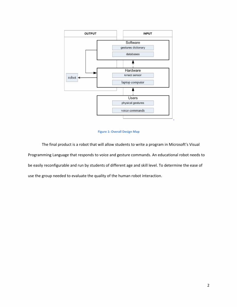
user. Below is a map of what a typical robotic system looks like that takes input from a user.
2
Figure 1: Overall Design Map
The final product is a robot that will allow students to write a program in Microsoft’s Visual
Programming Language that responds to voice and gesture commands. An educational robot needs to
be easily reconfigurable and run by students of different age and skill level. To determine the ease of
use the group needed to evaluate the quality of the human robot interaction.

3
Literature Review
Robot-Human Interaction
The field of Human-Robot Interaction (HRI) is defined as “an interdisciplinary research field
aimed at improving the interaction between human beings and robots and developing robots that are
capable of functioning effectively in real-world domains, working and collaborating with humans in their
daily activities” (Salvine, 2011). The successful completion of this project is dependent upon the robot’s
ability to respond to human command which requires a natural interface. Our sponsor, DEPUSH
Technologies has requested that we utilize the Microsoft Kinect to accomplish this interface. The Kinect
allows for the use of voice and gesture commands for control. For humans this is a very natural form of
communication, as it is also the means for human-to-human interaction. When studying the quality of
the HRI experience for a particular robot one needs to take task completion and personal experience
into consideration.
Task Completion
The task completion evaluation of a robot is aimed at evaluating the robot’s ability to complete
a task efficiently enough so that it is worth the human’s time to interact with the robot. There should
also be a sufficient library of functionalities so the robot can accurately respond to both the user and the
surrounding environment. Although obstacle avoidance is a secondary objective, the robot will still need
to locate the correct user and recognize gesture commands. The efficiency of one service is dependent
upon the efficiency of other service(s). An accurate measure of efficiency is error rates: the rate at which
the robot performs the task incorrectly. A high error rate will be detrimental to the overall functionality
of the robot. A highly efficient robot greatly increases the quality of the personal experience.

4
Personal Experience
The experience with the robot itself is a complex issue that can drastically alter the effectiveness
of the robot. This particular robot design is comparable to a service robot or “a semi-intelligent self-
propelling agent that is developed with the intention to operate with humans in home environments”
(Oestreicher, 2006). Although the robot’s environment might differ from a home environment, it will
remain similar regarding necessary maneuvers and will still serve as a service robot of sorts. “A person’s
experience of interaction is situated within a broad social and physical context that includes such things
as culture, social structures, and the particular environment they are interacting with” (Salvine,
2011).The classroom environment that this robot will be used in requires a personal experience that is
educational and entertaining. The user’s level of programming experience is also a major factor to
consider. Some of the requirements for interaction with a service robot are a cooperative interface,
simple structure, functions that are easy for humans to understand, and a gentle appearance
(Oestreicher, 2006). Students need to be able to navigate through the user interface with ease. The
services written need to be well documented and neatly written to allow for future improvements on
the platform.
Interaction Experience
All of the human robot interactions need to be predefined in some documentation. This is
typically done with a user interface map. This allows us to ignore all internal functionality and focus on
the interaction experience before delving into the system design. Documenting all interaction before the
system is developed ensures consistency throughout all interactions with the robot. This documentation
serves as an outline for the platform’s structure and is the easiest way to communicate robot
functionality to the end-user. It is also important that the user interface is easy to navigate and allows
for easy debugging.

5
Computer Vision
As the capability and portability of powerful computing systems improves, the role of computer
vision in mobile robotics is increasing (Connolly, 2007). These computing systems are able to form
detailed structural descriptions from image data provided by visible-light cameras and other image
sensors using a series of processes to condition the image and extract usable information. Despite the
computational complexity of fitting a structural description to raw image data, the quality of the output
is only limited by original sensor resolution, computation power, and the quality of the algorithms used
(Szeliski, 2011).
The use of computer vision in Robotics gained a large following from its early application in
industrial robots (Connolly, 2007). Industrial robots were a launch pad for computer vision due to their
negligible restrictions on power consumption and computational ability.
These robots have employed visible light cameras for a wide range of applications including
calibration, adapting to handle different products and recovering from positioning errors. As sensor and
processor technology improved, the technology found home on increasingly smaller, more mobile
devices.
As computer vision found home in an increasing number of industrial applications, it began to
work its way into the consumer market, eventually resulting in the Microsoft Kinect, which was released
into the North American market during November, 2010. The device, which held the Guinness World
Record for Fastest Selling Consumer Electronics Device for the year of 2010, was originally meant as way
for users to control video games by moving their body (Guiness, 2010). Needless to say, it was quickly
“hacked” by a multitude of independent software developers, eager to access the Kinect’s hardware for
their own purposes. Following the flood of open-source packages released only a few months after the
Kinect’s release, Microsoft released their own Kinect Software Development Kit (SDK) in June, 2011 so

6
any person with a Kinect and a Microsoft Windows computer could write their own programs using the
device’s impressive line of features.
Kinect Specifications
The large open-source software flood that followed the Kinect’s release popularized the
usefulness of the device for non-game applications. The Kinect boasts impressive depth, video, and
audio capturing capabilities that pose many advantages to a product developer seeking close integration
with humans (Leyvand, 2011).
These features, outlined in Figure 2, include the output of an 11-bit/pixel “depth” image as well
as a 24-bit/pixel Red-Green-Blue (RGB) image (Naone, 2012).
Figure 2: Kinect Features
The Kinect senses distance using an infrared emitter that projects a field of infrared points that
are distributed angularly uniformly. The Kinect uses a 1.3 megapixel CMOS MT9M001 digital image
•Infrared projector and camera give depth perception
•Onboard systems process raw data
•640x480 resolution – 11bits/pixel - Depth in Millimeters Infrared
•Picks up visual spectrum
•640x480 resolution – 30fps – RGB 8bits/channel
•Onboard down-sampling for less-capable host devices Camera
•Three circuit boards for onboard accelerometer, image, and audio processing
•Servo control Logic
•Limited camera FOV (57° Horizontal by 43° Vertical)
•Servo properly positions sensor body
•Sensor tilts 27 degrees Servo
•Four microphones
•16-bits/sample at 16kHz
•Physically downward facing Microphone Array
•Interfaces with MS Speech Recognition
•Echo cancelation, sound localization happens on host system Kinect SDK / MS-RDS

7
sensor. Distance information is extracted from the observed concentration of those points by an
infrared image sensor.
The color image sensor is a simple image sensor that outputs image data at a maximum
resolution of 640x480. This is done using a 1.3 megapixel CMOS MT9M112 image sensor. Both the
infrared and color are 1.3 megapixel sensors. The sensor detects color using Red, Green and Blue
channels (RGB) with a bit depth of 8 bits per channel. The device is also capable of downsampling the
output signal to lower frame rates and resolutions for less capable host-devices. This is particularly
useful for applications where computing power is limited. The onboard logic processes this in
combination with the infrared data on a separate circuit board.
In addition to the ability to downsample, the Kinect also has an onboard accelerometer that is
capable of measuring the sensor’s orientation and local acceleration. The motor is capable of tilting the
sensor 27 degrees vertically, which combines with the camera’s 43 degree vertical field of vision (Naone,
2012). The onboard logic also processes the audio signal from the microphone array.
The microphone array consists of four small microphones that record audio from the Kinect
environment with a bit depth of 16 bits per sample each and a sampling rate up to 16KHz. The sensor
then processes this into one signal that it transmits back to the host system.
Finally the Kinect SDK provided by Microsoft can perform a wide range of processes on the
incoming signal. Echo cancellation happens on the host system within the Kinect SDK in addition to
voice, speech and skeletal recognition. This allows for a high level of customizability at the application
end: system engineers can have a wide range of control over the processing tasks.

8
Robot Platform
The robot used is produced by Parallax and is known as the Eddie (Expandable development
discs for implementation and experimentation). It is a fairly recent product released at the end of 2011.
The robot is driven by two 12 V motors controlled by an eight core Propeller P8X32A microcontroller
(Eddie Robot Platform, 2012). This chip contains eight 32 bit processors that share a central hub and can
run simultaneously. This allows for an easier user experience when handling asynchronous events than
using interrupts, resulting in smoother performance. This simultaneous performance makes the chip
particularly useful when dealing with sensor integration, motor control and educational robotics which
are all important aspects of this project. The chip also has 32 KB of RAM and 32 KB of ROM, however
memory is not much of a concern since a laptop computer is connected to the system and runs all of the
user code (Eddie Robot Platform, 2012). Eddie uses a Microsoft Kinect sensor along with ultrasonic and
infrared sensors to collect environmental data. The package purchased from Parallax uses three Sharp
GP2Y0A21YK0F infrared sensors and two Parallax PING)))™ ultrasonic sensors which are located on the
front of the chassis. This creates a large blind spot behind the robot. In order to implement successful
obstacle avoidance algorithms, more sensors were obtained from the sponsor and attached to the back
of the robot. This is discussed further in the Design section.
All of the sensors are attached to the control board via copper wiring and a simple three pin I/O
(input/output) connection. The three pins connecting the infrared sensors are responsible for supply
voltage, output voltage level, and ground. The three pins connecting the ultrasonic sensors are
responsible for supply voltage, ground and output signal. The Propeller board provides multiple
different power levels to all of the devices required for the robot’s operation. The Kinect sensor requires
12V DC output. Since the motors require between 5.5 and 16V for operation, the same circuit is used to
power the sensor and motors. The circuit shown in Figure 3 below provides a 12V, 2.2A output.

9
Figure 3: Eddie 12V Supply Schematic
The Mini-USB B connection along with the ultrasonic and infrared sensors runs on 5V DC output. The 5V,
3A supply circuit is shown in Figure 4 below.
Figure 4: Eddie 5V Supply Schematic
Finally there is a 3.3V supply circuit shown in Figure 5 below. This uses 0.1 and 10 µF capacitors in
parallel to reduce the 12V input voltage to the desired level while keeping the output to 1A (Parallax).
Figure 5: Eddie 3.3V Supply Schematic

10
The laptop computer is connected to the control board via a USB to Mini-USB B connection. The
Propeller board uses a Prop Plug Mini-USB B connector, which is produced by Parallax. This has 4 pins
capable of a 3 M baud rate transfer (Parallax, 2012). This is shown below in Figure 6.
Figure 6: Parallax Prop Plug Mini-USB B Connector
It is capable of running on 3.3 or 5 V supply voltage. This Propeller control board runs the connection on
5V. The cable used is a simple twisted pair cable available from most electronics retailers. These are
made of copper wires coated in an insulating material and twisted together. Microsoft Robotics
Development Studio does require an internet (preferably wireless) to function. Therefore, a reliable
internet connection is required. An advantage of this feature is that it allows for easy tuning of the
robots functionalities through a web interface. Another computer can access this interface to train
gestures and set speech commands on the fly.
The unassembled cost of the package is $1,249, however this does not include the laptop
computer and Kinect sensor. Figure 7: Robot Design below shows the assembled robot with laptop and
Kinect sensor. It consists of two driven wheels and two idle casters for support. The robot is also circular
in shape, with one shelf for drive components and batteries and another for the control laptop. The
Kinect is placed on top of a vertical arm.

11
Figure 7: Robot Design
Microsoft Robotics Developer Studio
Microsoft’s Robotics Developer Studio (MS-RDS) is a robot operating system software
environment that allows easy development of a wide variety of robots. By providing programmers with
a software environment where normally difficult problems, such as multitasking, simulation and remote
monitoring, are solved already, Microsoft is hoping that MS-RDS will become a staple in the robotics
industry. Our sponsor has also requested that we use MS-RDS for this project.
Multitasking is easily accomplished through the use of the Concurrency and Coordination
Runtime. A group of threads can be assigned tasks through a Dispatcher Queue, which presides over the
group of threads. By passing a task, in the form of a lambda-expression (“delegate” in C#) or method, to
the Dispatcher Queue, a task is scheduled for execution. Tasks in the Dispatcher Queue can depend on
actions from other threads or outside processes using Arbiters, which wait on input from ports before
tying up a thread. By spawning several tasks, who all post their result on the same internal port, the
developer is able to easily perform several concurrent tasks, yet re-join the data when serial processing
is needed.

12
The simulation environment has the capability of displaying 3-D visualizations of the robot and
its surrounding environment as well as performing basic physics simulations using NVIDIA’s PhysX
engine. The simulation environment is useful when the robot hardware is not available or it is expensive
to crash. It could also be useful in an educational robot, where students are assigned homework but the
robot cannot leave the lab.
Remote monitoring is accomplished using Decentralized Software Services, an application model
that allows for services running on the robot to exchange messages with another service. By transferring
information using the Decentralized Software Services Protocol (DSSP, an extension of Simple Object
Access Protocol, SOAP), a mobile robot can transmit and receive valuable troubleshooting and
debugging information to and from the user easily.
Basic research into MS-RDS reveals that it has a very steep learning curve, and it can be difficult
for students to learn to use. Although the software does support a drag-and-drop visual programming
language, this language has several limitations when implementing complex functionality, such as
gesture recognition. It is our belief that most complex functionality needs to be implemented in C#.
Programming Languages
C#
There are several advantages in using C# over C++ for developing Windows applications. The
first and foremost advantage is the fact that C# is the only actively supported .NET language available for
us in MSRDS. Second, the syntax can be very similar to Java, with the exception of delegates, data
members, and a few other scenarios, this makes it easy to learn for most students. Also, C# has
established itself in recent years in industry. It is beneficial to have this knowledge if you plan to proceed
with a career in windows programming.

13
C# is a modern, very high level programming language. It's extremely easy to learn and has
many similar features to other high-level languages, including memory management.
There is also a huge amount of knowledge about C# that is freely shared, openly debated, and
which future development is decided by the community. Table 1 below lists some general advantages of
using C# and why it is the best choice for this project.
General Advantages Project Specific Advantages
+ Checks for array bounds
+ Autoboxing - every type can be treated as if it
inherits from object
+ Supports constructor-chaining (one constructor
can call another constructor from the same class)
+ Exceptions have access to a stack trace
+ Advanced runtime type information and
reflection
+ Built-in support for threads
+ No need for header files and #includes
+ No fall-through on switch-statements
+ Attributes can be attached to classes and
retrieved at runtime
+ No forward declarations required, classes can be
arranged at will
+ Structs and classes are actually different (structs
are value types, and have no default constructor; in general they cannot be derived from)
+ Huge .NET-Framework library available. There
are many off-the-shelf modules (such as speech recognition, gesture recognition, and text-to-speech) we can use.
+ It is easier and faster to develop in.
+ Native support for Concurrency and
Coordination Runtime
Table 1: Advantages of C#
VPL
The end user of this product will be programming desired functionalities in Microsoft’s Visual
Programming Language. “Microsoft Visual Programming Language (VPL) is an application development
environment designed on a graphical dataflow-based programming model” (MSDN, 2012). Instead of a
user programming in text, VPL uses a series of activity blocks that are all interconnected. The input to
one activity block can come from the output of another, and each connection represents type of
operation on that service or activity. Existing activities can be combined or the user can create activities

14
in VPL or write their own in C#. For example, this project’s final prototype features a gesture recognition
service, making it possible for users to activate VPL code when a certain gesture is recognized. The
service, written in C#, shares the same behavior that a user-written service would have.
VPL provides a visual representation of the flow of the program making it easier for beginners to
use. It is targeted for beginners with basic concept knowledge; however programmers of all skill levels
can use it to create quick prototypes or systems that can easily be reconfigured. Figure 8 below shows a
sample program written in VPL. Variables and data types can be set and fed into a certain activity. For
example a string fed into the text to speech service when run will produce an output to the speakers of
a Microsoft provided voice saying the desired string.
Figure 8: Activity blocks have connections that represent messages sent from one activity to another (MSDN, 2012)
“An activity block activates and processes the incoming message data as soon it receives a valid
incoming message… An activity may have multiple input connection pins, each with its own set of output
connection pins... Output connection pins can be one of two kinds: result output (also called a response
output) or notification output (sometimes also referred to as an event or publication output)” (MSDN,
2012). This can be seen below in Figure 9. The input can either be an output from another activity or a
piece of data defined by the user. The notification output can be very useful for users debugging his or
her program, as it provides insight into where exactly the error occurred.

15
Figure 9: VPL Connections Pins (MSDN, 2012)
Appendix C shows a sample VPL program that allows the user to train and recognize gestures.
Shown is the main diagram, the speech recognition and drive controller programs.
Project Sponsor This project was sponsored by Depush Technology of Wuhan. Founded in February 2001, the
company’s main focus has been to improve the quality of engineering education in China. The company
provides teaching platforms, textbooks, other course materials and teacher training services to 500
institutions throughout the country. The company currently markets 12 robots. Three are classified as
basic educational robots and the remaining nine are considered professional educational robots. Most
of their products are available with any of the company’s three microcontroller boards. All robots are
capable of accepting more sensors or breadboard installation.
The first basic educational robot is the Baby Car Robot. This is a miniature autonomous robot
platform which runs on a single chip controller. The package comes with an attached breadboard
allowing students to experiment with different circuits. There are three different versions of this robot
available each using a different microcontroller teaching board produced by Depush. The robot comes
equipped with two photo-resistor sensors, infrared sensors and two tentacle sensors.
The second basic educational robot is the Two Legged Walking Robot. This is a 25 cm tall walking
robot made of aluminum and brass all made using a CNC machine and is treated with an anti-corrosive
16
material. Extra mounting holes are available for users to incorporate additional peripherals. This model
also comes fitted with a bread board for user circuit experimentation. This robot can also be purchased
with any of the three microcontroller teaching boards produced by Depush It comes equipped with two
photoresistors and infrared sensors.
The final basic educational robot is the Sumo Robot. This robot is designed for students to
program and compete in mini-sumo robot competitions. It also has bread board for experimentation
including 2 QTI line tracking sensors and infrared sensors. This can also be purchased with either of the
three microcontroller teaching boards available.
The first professional educational robot is the Humanoid Robot. This robot has 16 degrees of
freedom but cannot move its head. It can walk, run, jump, execute a push-up, balance on one leg,
execute a somersault and travel down stairs. The robot is equipped with over-current protection and
supports Bluetooth control. Unlike the other products, the Humanoid Robot is only available with an
ATMEL MR-C3024 control board. This can be programmed in C or RoboBasic and runs on 1000 mAh
batteries. The robot is capable of 7.4 kg/cm of torque.
The next two professional educational robots are the Six Legged Rectangular Robot and Six
Legged Circular Robot. Both of these bionic robots run using 18 motors allowing each leg to have three
degrees of freedom (vertical, horizontal and ankle). They both run on 6V DC power supply and are
available with any of the three Depush microcontroller teaching boards. The difference between the
two is the shape of the chassis. As their name implies, one is rectangular and one is circular.
The next two professional educational robots are the Six Legged Cylindrical Iron Beetle Robot
and the Six Legged Iron Beetle Robot. Similar to the two robots described above, the difference between
these robots is the shape of the chassis. Unlike the two described above, these bionic robots do not
have an ankle motor so there are only 12 total motors. This reduces the degrees of freedom for the legs

17
to two degrees. These also run on 6V DC power supply and are available with any of the three
microcontroller boards.
The next two professional educational robots are the Four Legged Cylindrical Iron Beetle Robot
and the Four Legged Iron Beetle Robot. These are almost identical to the six legged versions besides the
number of legs. This also reduces the number of motors on the robot to eight.
The final two professional educational robots are mechanical arms with grippers. They are
available with five or six degrees of freedom and with any of the three microcontroller boards. Similar to
other Depush robots, they run on 6V DC power supply. Motors are located on the base, shoulder, elbow,
wrist and gripper. Pictures of all of these Depush products including the microcontroller boards can be
found in Appendix A.
The final prototype produced at the end of this project is very different from any other products
offered by Depush. The Parallax Eddie uses a more advanced controller board, along with a highly
improved sensor array. Although some current Depush products use infrared sensors, none use
ultrasonic sensors or the Kinect sensor. The chassis is much larger than any current Depush products
which allows for the use of a laptop computer for processing power.
Educational Robotics Educational robotics is a rapidly advancing field, not only regarding number of participants but
the age at which students start. Robotics is emerging throughout multiple levels of the education system
and, in China. Depush is one of the top producers in educational robotics material. Dan Kara, an industry
recognized expert on robotic trends, and Lloyd Spencer, President of CoroWare Robotics, released a
virtual conference series in 2011 on open platforms for education & research robotics. They list a few
critical capabilities of an educational or research robot. Table 2 below lists the capabilities that are

18
applicable to this project. Some of the capabilities are controlled by the sponsor and are indicated as
such.
Critical Capabilities Project Team Project Sponsor
Intuitive, Multi-Modal HRI X
Safe Robot Behavior X
Positioning & Navigation X
Configuration, Re-Configuration, Adaptation X
Nano-Manufacturing X
Green Manufacturing X
Adaptable & Reconfigurable Manufacturing Systems X
Autonomous Navigation X
Model-Based Integration & Design of Supply Chain X
Quantitative Diagnosis & Assessment X
Table 2: Critical Capabilities of an Educational Robot
A successful educational robot should have the characteristics listed above. The project team is
implementing a user interface that is easily reconfigurable. The gesture and speech recognition services
allow for intuitive human robot interaction. The project team also implemented obstacle avoidance and
follower services that allow for safe, autonomous robot navigation. Descriptions of these services can be
found in the Design section of this paper, and a quantitative diagnosis and assessment can be found in
the Analysis section below. The manufacturing capabilities are important for the sponsor to take into
consideration, but are out of the project team’s control.

19

20
Methodology
This result of this project is a mobile robot car which uses the Microsoft Kinect sensor as a visual
and auditory sensor serving as a robotics education tool. This prototype improves on previous designs
by using the Kinect sensor to increase computational speed for environmental recognition. To produce
such a prototype required careful development of the product starting with identifying the exact
purpose of the robot. The full project description as provided by the sponsor can be found in Appendix
B.
Purpose
The purpose of this project is to explore the use of a Microsoft Kinect on a mobile robot and
evaluate its potential as a robotics sensor. The mobile robot was designed for application in robotics
education. In order to best accomplish this purpose, we developed a list of objectives that we hope to
accomplish with our prototype. Our initial understanding of the project definition was that the final
product would be used to assist teachers in a variety of classroom tasks, but after meeting with the
sponsor we learned that the desired application is to provide a platform that is easy for students
learning robotics to learn with. The objectives of this project are:
1. Provide our sponsor with a comprehensive review of the feasibility of using the Microsoft Kinect
for gesture and speech recognition
2. Develop a program in Microsoft's Software Development Suite that can detect and respond to a
designated list of voice and gesture commands
3. Implement basic obstacle avoidance behavior using existing platform and available obstacle
avoidance algorithms
4. Provide the sponsor with a well-documented prototype that will encourage further
development

21
Objectives
Objective 1: Kinect Technology
The Microsoft Kinect is a computer vision technology that combines a variety of hardware to
capture image, depth, and sound. It is also a fairly inexpensive piece of equipment that is readily
available to the public. This objective is aimed towards gathering a complete knowledge of what the
Kinect is capable of and how this is applicable to this robot design. The goal is to take full advantage of
the data collected by the Kinect. Research was conducted on the theoretical limitations of the Kinect
and testing was conducted on the actual limitations. The follower service is dependent on the Kinect’s
field of vision. The group tested the function of the Kinect in a variety of environments. The limitation of
the Kinect in regards to the lighting in the room was also tested. The group tested with different users
with different clothing to ensure consistency in the results. The gesture recognition capabilities of the
Kinect rely on the sensor’s ability to track skeletons. The skeletal tracking feature was tested by different
users to ensure that gestures could be recognized regardless of body type. The Kinect tracks 20 different
joints on the skeleton, so the team tested the gesture recognition service varying the relevant joints to
determine how the different combinations affect the effectiveness of the gesture.
Objective 2: Voice and Gesture Control
The final prototype is to be used as an educational platform; therefore the result of this
objective is to produce a service allowing the user to train and recognize gesture and voice commands
using the Kinect sensor, all through VPL. Microsoft’s open source voice recognition served as a starting
point for the team’s service, but there is no available Microsoft open source service for gesture
recognition, so this service had to be completely developed by the team. The services are implemented
using Microsoft’s Robotics Developer Studio. Unlike speech recognition, there is not a library for
gestures. This requires a program that sets up a library of user inputted gestures that the robot can

22
respond to. The gesture trainer service is responsible for recording a new gesture. The gesture manager
is responsible for storing recorded gestures in a library. Finally, the gesture recognizer determines which
gesture the user performs and matches it to one stored in the library. It is important that all services are
documented properly.
Objective 3: Self-preservation
Obstacle avoidance was originally considered as a secondary objective. The robot purchased
from Parallax came equipped with three infrared sensors and two ultrasonic sensors mounted to the
front of the chassis. These were utilized effectively for forward obstacle avoidance. After several
instances of the robot backing into walls, it was decided that we needed to add five rear facing sensors
to the robot to avoid backing into obstacles. There are many obstacle avoidance algorithms available, so
the team researched what was available and chose one. It would not have been feasible to write our
own algorithm in the time given. The obstacle avoidance service incorporates all ten sensors, ultrasonic
and infrared.
Objective 4: Final Product
The final outcome of this project is to integrate these programs, the Microsoft Kinect sensor, a
laptop computer, and robot. It should be able to successfully respond to commands and avoid obstacles
with a low error rate. The user should have a good personal experience with the robot. This was
accomplished by integrating all of the services written and ensuring their proper functionality together.
Project Planning To complete the project on schedule, the final system was divided into its major components.
The group then developed a project schedule listing all of the parts to be completed and the dates they
needed to be completed by. The project team was then divided into subgroups with each responsible
for one aspect. The main focuses of the teams were evaluating the Eddie platform, conducting market
23
research on existing products, examining existing obstacle avoidance algorithms, and developing the
gesture and speech recognition services.
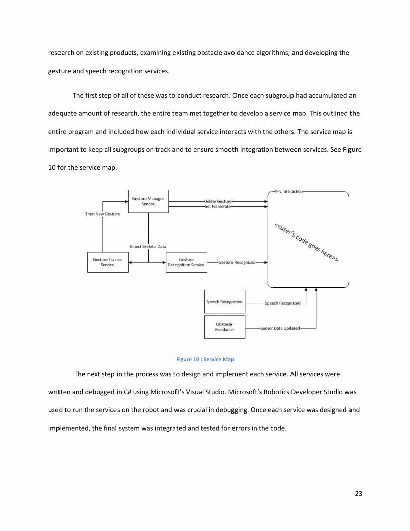
The first step of all of these was to conduct research. Once each subgroup had accumulated an
adequate amount of research, the entire team met together to develop a service map. This outlined the
entire program and included how each individual service interacts with the others. The service map is
important to keep all subgroups on track and to ensure smooth integration between services. See Figure
10 for the service map.
Figure 10 : Service Map
The next step in the process was to design and implement each service. All services were
written and debugged in C# using Microsoft’s Visual Studio. Microsoft’s Robotics Developer Studio was
used to run the services on the robot and was crucial in debugging. Once each service was designed and
implemented, the final system was integrated and tested for errors in the code.

24
Design
Follower Service The follower service was designed based on open source code available from Microsoft. This
service uses a PID control loop to accurately determine the distance and angle the robot should travel.
The follower service uses a proportional integral derivative (PID) control loop. This uses the
feedback signal from the system to make adjustments to the motor drive output. The feedback is used
to generate an error relative to the command. “The proportional term (P) gives a system control input
proportional with the error. Using only P control gives a stationary error in all cases except when the
system control input is zero and the system process value equals the desired value” (Gasbaoui, 2009). If
the constant for the proportional term is low, then the system will take a long time to get to the correct
speed, but if the value is too high it will overshoot the desired speed and take just as long to average
out. “The integral term (I) gives an addition from the sum of the previous errors to the system control
input. The summing of the error will continue until the system process value equals the desired value”
(Gasbaoui, 2009). These can be used together without the derivative term; however the follower service
uses all three. “The derivative term (D) gives an addition from the rate of change in the error to the
system control input” (Gasbaoui, 2009). The inclusion of the derivative term in the calculation improves
the response to a sudden change in the system state. The maximum drive of the motor, 100 percent,
was set as the maximum integrator for the loop and the minimum was set to zero. A simple, web-
accessible user interface is used to tune the loop. Figure 11 below shows this window. Trial and error
adjustments led to the proper values for this robot. There is minimal oscillation in either directional
plane.

25
Figure 11: Follower PID Configuration Page
A PID control loop based follower is very hard to implement in Microsoft VPL due to the
complex data structure that skeletal data has. It was important for the project team to implement this in
Microsoft Robotics Developer Studio so students would be able to easily have the robot follow them.
Since the end user will be programming in VPL it provides the versatility for use by students of multiple
age and skill levels.
Gesture Recognition Service Gesture interaction with a computer system, from the user’s standpoint, takes two different
forms: static and dynamic. In static interaction, the user achieves one, stationary pose in order to
interact with the system, whereas dynamic recognition requires the user to move through a series of
poses in order to control the robot. Each form of interaction heavily affects the amount and format of
data collected from the user. The pose, which contains the position of each of the user’s joints,
represents the user’s state at only one point in time. For static recognition this alone adequately defines

26
a gesture, but for dynamic gesture recognition a more complex data structure that represents the user’s
pose over time is required.
It was decided that this project should aim for dynamic gesture recognition, but should also be
able to recognize single poses. This poses an interesting design challenge in that each gesture represents
a rather large body of data that changes drastically depending on the type of gesture recognition
algorithm used. To overcome this challenge, we encapsulated the data types required for storing
gestures. See Figure 12 for a preliminary Unified Modeling Language (UML) diagram showing a possible
set of entity classes.
Figure 12: UML Diagram of a Gesture Class
Gesture
+Poses: Pose[1..*]+Name: string+LocalicationData: Localizer
Pose
+Joints: Joint[0..*]+Timestamp: DateTime
+DistanceFrom(Pose p): double+GetJoint(JointType t): Joint+Localize(Localizer l): Pose
Joint
+Type: JointType+Position: 3DPoint
+EuclideanDistance(Joint j): double

27
It is immediately apparent that the data is hierarchal, with Gesture being the parent class,
referencing many poses and each Pose containing many Joints. This becomes particularly challenging
when multiple lookup operations are required for each new frame. In order to keep the gesture
recognition in real-time, we optimized the Gesture Recognition service to:
1. Perform a minimal number of lookup operations for each frame.
2. Run computationally expensive operations in parallel
3. Streamline memory-write operations so that they occur in groups
With these optimizations we were able to perform real-time gesture recognition at frames
exceeding 10fps with unnoticeable delay between gesture completion and recognition. To actually
perform the gesture recognition, a Dynamic time Warping algorithm was implemented. To implement
this in an asynchronous environment, each Gesture is given a state representing the index of the last
matched pose and the current distance of that gesture to the current stream of poses. For each frame
that is observed by the Kinect, the algorithm compares that frame to all of the poses within a pre-
defined window to the last matched pose and either matches the pose or rejects it. If a Gesture
accumulates too much distance, or the skeleton leaves the frame, the gesture is reset to a distance and
frame index of 0. See Figure 13 below for a flowchart of the Gesture Recognition functionality.

28
Figure 13: Gesture Recognition Service Map
The Gesture Processing task is the most computationally expensive task performed, as it
involves calculating the distance between the new Pose from the Kinect and each of the adjacent frames
as well as comparing the frame to others and localizing it to the specific joint defined in the gesture.
Speech Recognition Service Speech recognition (SR) converts spoken words to written text. As a result, it can be used to
provide user interfaces that use spoken input. The Speech Recognizer service enables us to use speech
recognition in our application. Speech recognition is based on the Microsoft Speech Recognition Engine
API, a special type of software that can imply a string of text from a given audio signal. The SR engine is
installed with the operating system. This leads to the problem that this service works only when the aim
language is supported by the user’s operating system (MSDN, 2012). In this project, in order to
successfully run the service, we require the use of an English version a Windows operating system.
RDS (Robotics Developer Studio) offers two existing services, the SpeechRecognizer and
MicArraySpeechRecognizer. The former one is used for speech recognition using an ordinary
microphone. The latter one is used for speech recognition using the Kinect microphone array. In this
project, as we use the Kinect as the audio sensor, so we used the latter one. To successfully implement

29
this service with other services written by the group, we had to rewrite this service to combine it with
the Kinect service. As a result, in our package, we can include the Kinect service, replacing the original
one. This is due to a documented bug in the Kinect SDK in which, if the Skeletal Recognition engine is
initialized after the audio sensor, then the audio sensor will be stopped (MSDN, 2012). We needed to
make sure that each time the Skeletal Engine is restarted, the audio stream is reinitialized.
The MicArraySpeechRecognizerservice provides functions such as operations on grammar,
speech detection, offering a confidence of the recognition and giving the desired response. The specific
operations and notification are described below.
Operations
Table 3 below shows the requests and notifications supported by the Speech Recognizer service
as listed in the MSDN support database.
Operation Description
Get Returns the entire state of the Speech Recognizer service.
InsertGrammarEntry
Inserts the specified entry (or entries) of the supplied grammar
into the current grammar dictionary. If certain entries exist
already a Fault is returned and the whole operation fails
without the current dictionary being modified at all.
UpdateGrammarEntry
Updates entries that already exist in the current grammar
dictionary with the supplied grammar entries. If certain entries
in the supplied grammar do not exist in the current dictionary
no Fault is returned. Instead, only the existing entries are
updated.
UpsertGrammarEntry
Inserts entries from the supplied grammar into the current
dictionary if they do not exist yet or updates entries that
already exist with entries from the supplied grammar.
DeleteGrammarEntry
Deletes those entries from the current grammar directory
whose keys are equal to one of the supplied grammar entries. If
a key from the supplied grammar entries does not exist in the
current directory no Fault is returned, but any matching entries

30
are deleted.
SetSrgsGrammarFile
Sets the grammar type to SRGS file and tries to load the
specified file, which has to reside inside your application's
/store folder (directory). If loading the file fails, a Fault is
returned and the speech recognizer returns the state it was
before it processed this request. SRGS grammars require
Windows 7 and will not work with Windows Server 2003.
EmulateRecognize
Sets the SR engine to emulate speech input but by using Text
(string). This is mostly used for testing and debugging.
Replace
Configures the speech recognizer service, or indicates that the
service's configuration has been changed.
SpeechDetected
Indicates that speech (audio) has been detected and is being
processed.
SpeechRecognized Indicates that speech has been recognized.
SpeechRecognitionRejected
Indicates that speech was detected, but not recognized as one
of the words or phrases in the current grammar dictionary. The
duration of the speech is available as DurationInTicks.
Table 3: Speech Recognizer Requests & Notifications
We found that both Speech Recognizer services worked best when the dictionary was defined
prior to service start, in the initial state configuration file. Since this file is an XML file, we wrote a basic
program to modify this file while sheltering the user from manually changing XML. A screen shot of this
program can be found in Figure 14.

31
Figure 14: Speech Recognizer Configuration File Editor
Initial state properties
Table 4 below shows the data stored in the SpeechRecognition state.
Name Type Description
IgnoreAudioInput Boolean
Specifies whether the speech service listens for audio
(spoken) input (when this is set to false). This may useful
for turning off the SR engine temporarily(or when using
emulation recognition).
GrammarType GrammarType
Specifies the type of grammar the SR engine will use,
either a simple Dictionary grammar or SRGS grammar.
SrgsFileLocation string
Specifies the SRGS grammar file to be loaded (only used
if you set GrammarType to SRGS).
Table 4: Speech Recognition Initial State Properties
Setting GrammarType to the Dictionary configures the service to use a simple dictionary-style
grammar. A dictionary-style grammar is a list of entries that each consist of a set of words for the speech

32
engine to listen for and an optional corresponding semantic tag that represents that recognition (MSDN,
2012). For example, you might define an entry like, Tell me the time, and call its semantic tag,
TimeQuery. This is the only type that we explored as a part of this project due to time constraints.
The SpeechRecognizerGui service can also be used to generate a Web page that enables the
user to enter and save a simple dictionary grammar file. For further details, information on the
SpeechRecognizerGui service can be found on the MSDN database.
Service State
By using a Get request, the general state of the Speech Recognizer service can be returned,
however the recognition state is provided by the SpeechDetected, SpeechRecognized, and
SpeechRecognitionRejected notifications. SpeechDetected returns StartTime, which is the time when
the SR detects an audio input. Table 5 below shows the return notification message from the
SpeechRecognized service.
Name Type Description
Confidence float
Return a value between 0 and 1 indicating the SR
engine's rating of the certainty of correct recognition
for the phrase information returned (higher is better).
However, it is a relative measure of the certainty and
therefore may vary for each recognition engine. If -1 is
returned the speech engine does not provide
confidence information.
Text string Returns the words recognized.
Semantics
RecognizedSe
manticValue
Returns the semantic value object(s), if any, of the
recognized words.
DurationInTicks long integer
Returns the duration of the utterance recognized.
There are 10,000,000 ticks per second.
Table 5: Speech Recognition Service State Characteristics
33
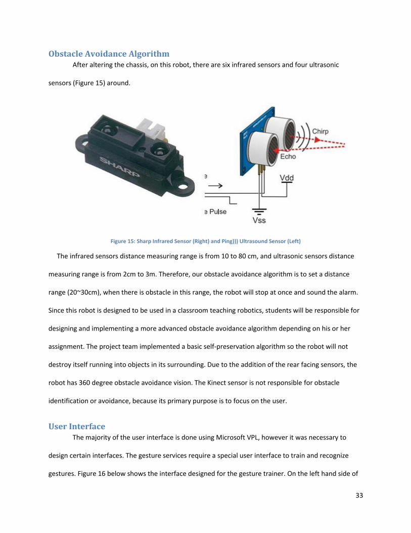
Obstacle Avoidance Algorithm After altering the chassis, on this robot, there are six infrared sensors and four ultrasonic
sensors (Figure 15) around.
Figure 15: Sharp Infrared Sensor (Right) and Ping))) Ultrasound Sensor (Left)
The infrared sensors distance measuring range is from 10 to 80 cm, and ultrasonic sensors distance
measuring range is from 2cm to 3m. Therefore, our obstacle avoidance algorithm is to set a distance
range (20~30cm), when there is obstacle in this range, the robot will stop at once and sound the alarm.
Since this robot is designed to be used in a classroom teaching robotics, students will be responsible for
designing and implementing a more advanced obstacle avoidance algorithm depending on his or her
assignment. The project team implemented a basic self-preservation algorithm so the robot will not
destroy itself running into objects in its surrounding. Due to the addition of the rear facing sensors, the
robot has 360 degree obstacle avoidance vision. The Kinect sensor is not responsible for obstacle
identification or avoidance, because its primary purpose is to focus on the user.
User Interface The majority of the user interface is done using Microsoft VPL, however it was necessary to
design certain interfaces. The gesture services require a special user interface to train and recognize
gestures. Figure 16 below shows the interface designed for the gesture trainer. On the left hand side of

34
the window, users can input a string representing the name that he or she would like associated with
the gesture. Next, the user decides which joint to set as the origin and which joints are pertinent to the
successful completion of the gesture. The right hand side of the window displays the joints of the user in
view of the Kinect that have been selected. By clicking the “Start Training” button, the service will begin
recording the user’s movements. This same button is used to stop recording the gesture.
Figure 16: Gesture Trainer User Interface
The next service requiring its own user interface is the gesture manager service. The interface
for this service is and XML web interface. This is shown below in Figure 17. This interface allows users to
set the frame rate that the Kinect uses to collect data. It also lists all of the gestures that have been
added to the dictionary using the gesture trainer service and the number of frames of the gesture. This
interface includes a feature that allows users to remove a gesture that has been stored. It also allows
users to retrieve gestures stored in any location on the computer.

35
Figure 17: Gesture Manager Web Interface
The final service requiring its own user interface is the gesture recognizer service. The group
designed two interfaces for this. One is web based and the other opens up its own window. The first is
shown below in Figure 18. Most functionalities of the recognizer service are available in the latter of the
interfaces. The web interface allows users to hide or show the interface window, and to pause the
recognition service.
Figure 18: Gesture Recognizer Web Interface
The second user interface for the recognizer service can be seen below in Figure 19. This
window displays the current skeletal data as seen by the Kinect in the leftmost panel. In the center
panel, the gesture in the dictionary that matches the attempted gesture the closest is displayed.
Underneath this is a drop down box which displays the name of the gesture, and below that is the frame
count of the attempted gesture and the distance away from the recorded gesture it is. If the attempted
gesture is too far off from the recorded gesture, the distance will be large and the service would not
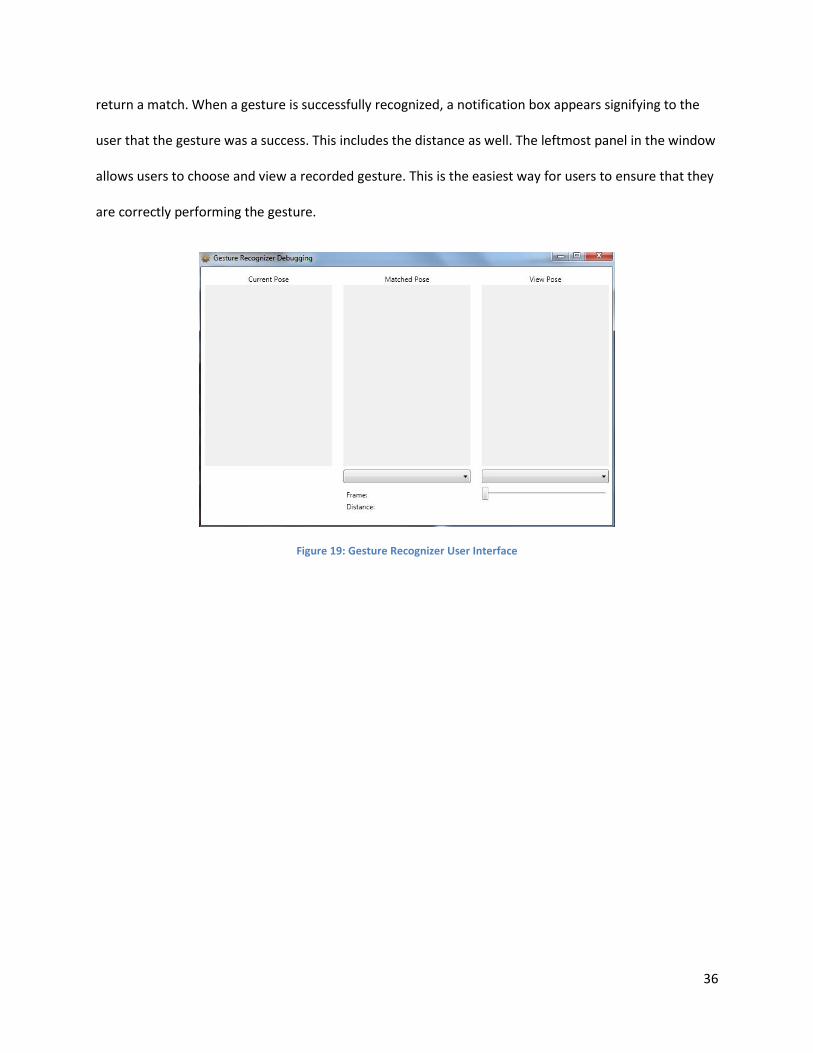
36
return a match. When a gesture is successfully recognized, a notification box appears signifying to the
user that the gesture was a success. This includes the distance as well. The leftmost panel in the window
allows users to choose and view a recorded gesture. This is the easiest way for users to ensure that they
are correctly performing the gesture.
Figure 19: Gesture Recognizer User Interface
37
Analysis This section analyzes all of the services implemented by the project team, including an analysis
of the Kinect sensor as the primary computer vision device. The restrictions and limitations of both
software and hardware are discussed. The team also encountered a few challenges that slightly
hindered the completion of the project. Although the team had no control over hardware limitations,
most issues with the software were corrected.
Final Prototype Evaluation
Kinect as Computer Vision
The Kinect sensor was used as the main computer vision device for this robot. It is more
effective than previous stereo vision techniques, although it does have some disadvantages. One of the
problems noted about the Kinect deals with the skeletal recognition capability. The Kinect occasionally
misinterprets inanimate objects as the user and “tracks” its skeleton. This occurred on a variety items
such as an air conditioner and a wall. One of the environments that the team tested the Kinect in was in
a narrow hallway. When walking around the robot the walls of the hallway were just wide enough to
allow the robot to turn around without running into a wall, however sometimes it would lose focus on
the user and begin “tracking” another skeleton on the wall. This is a minor complication and only
occurred on certain occasions, but it is worth making note of.
Another apparent problem with the Kinect deals with the skeletal recognition capability. Certain
users were easily tracked while some were recognized and tracked without a problem. Without any
changes to the code in between testing the follower service was run using two different users. One user
was wearing a black shirt and one was wearing a white shirt. The Kinect would fail to recognize the user
in the black shirt while tracking the user in the white shirt with precision. In both scenarios the primary
user was the only person in the sensor’s field of vision. This is another minor technical complication,
however it still is noteworthy.

38
The final point to be made about the Kinect is a hardware limitation which will most likely
continue to be a restriction on the Kinect for future models. The frequency of light used by the infrared
sensor restricts use to indoor environments. When the sunlight hits the infrared sensor the Kinect is no
longer able to correctly gather and process depth information. Since the application of this robot
involves a classroom setting, this should not be a major issue. It is important to note that even stray
sunlight that comes through windows will cause the robot to react unpredictably.
Despite these complications the overall functionality of the Kinect sensor far outweighs any
current market competition. When the skeletal tracking service correctly identifies the user it accurately
locates joint positions and in addition to following the user can successfully recognize when the user
changes a joint position. Since all people are proportionally different, the Kinect sensor will identify a
gesture using a confidence value based on the trained gesture and the user input. Also, once the PID
control loop discussed earlier was calibrated correctly the Kinect didn’t have any problems determining
the distance to the user allowing the robot to follow the user and stop at the correct distance.
Gesture Recognition Performance
Due to the asynchronous design of the Gesture Recognition service, we noticed many
interesting phenomena. The final application allows the user to select one joint as an origin and a subset
of the skeletal joints to use for the gesture. All joints not selected are ignored and the position of each
joint that is used in the gesture is defined with respect to the origin joint.
In some scenarios, this results in two or more gestures being recognized from one input gesture.
This can be either advantageous or inconvenient depending on the user’s intentions. When a gesture is
recognized, a Gesture Recognized notification is sent to all subscribers of the gesture recognition service
– The body of this message contains both the name of the gesture and the distance between the trained

39
and observed gestures. This allows the user to filter out potentially false gestures using logic developed
in VPL.
For future revisions of this service, we recommend that some coding effort be spent on
developing the gesture recognition system so that it:
is more efficient, to allow higher frame rates on less-capable host systems
allows for editing gestures in a graphical interface after they are trained
supports a set of unused gestures that can be activated at runtime as the user needs and
deactivated once they are not needed, to conserve processing power
has a more robust web-interface, to support remote operation
The gesture recognition system that we have designed, although introductory, is a very valuable initial
effort in the field of gesture recognition and that it has the potential to be a unique and attractive
product.
Speech Recognition Performance
At the beginning of the project, we planned to write a new service that is derived from the
Microsoft SpeechRecognition service. It was soon realized that this was unnecessary, as the original
service contains all the functions needed. Through our research, this service can effectively detect the
speech and recognize them. By using the Kinect Microphone Array, we can also compare the signals get
from different direction. This make the system have the potential to detect the direction of the source
of the sound. This function is not realized in our project, but is the responsibility of the user
programming in VPL.
It also provides a parameter called 'confidence' that shows the reliability of this detection. This
gives the developer an easy way to balance the sensitivity and accuracy. If we set a high threshold value,
the accuracy increases as the sensitivity decrease, and vice-versa.

40
From the team’s experience during the testing of this service, the performance this service still
depends on many environmental factors, such as the background noise, the accent of the instructor, etc.
The accent of the speaker has a great effect on the final confidence of the detection. We also found that
the system can detect the speech even when the speaker changes the order of the words in the
command, only with a little bit lower confidence. Both of these two problems may lead to the
misunderstanding of the user’s instruction. In conclusion, the Speech Recognition service performs
effectively, but still needs future improvements to be more reliable.
Economic Analysis To provide a complete analysis of the cost of such a product, one needs to consider both the
cost of the components plus the man hours put into designing the services. It is important to note that
this analysis excludes the laptop computer and any incidental software costs (if the users desired to
program in Microsoft Visual Studio and was not a student there is not a free version available).
Microsoft VPL is free software as is Microsoft Robotics Developer Studio.
First, the retail cost of the hardware will be discussed. As described above, the cost of the Eddie
Development Platform is $1,249 unassembled and not including the Kinect sensor and laptop computer.
Also, this price does not include the additional five sensors added to the chassis. The average price of a
Kinect sensor is $149.99. Purchasing one Ping)))TM Ultrasonic sensor from Parallax costs $28.49, or a
pack of 4 can be purchased for $99.99. Unfortunately, neither of these prices includes the mounting
stand. The individual sensor is available with the mounting stand for $39.99. The Sharp infrared sensor is
not available in bulk, but cost $12.99 individually without the mounting stand, and is not available with
the mounting stand. The Eddie platform comes disassembled and Parallax claims four to six hours of
assembly time. The total hardware package excluding the laptop would cost just under $1,600. The
Kinect sensor requires a laptop with at least for cores to run all of the services written. The CPU was
almost overloaded on a two core processor without running gesture recognition.

41
The development cost of the services designed by the project team will be discussed in hours of
programming and debugging time, not including how much it would cost per hour to pay the
programmer. Over the seven weeks of the project, the team put in just over 280 hours of work into the
programming. An entry level programmer’s average hourly pay is about $25. For 280 hours of work this
would cost a company about $7,000 in development costs. Depush provides educational robotics
products to 500 institutions throughout China. If one of these robots was sold to every institution
Depush provides robots to, they would break even selling them at $1,614. A reasonably expected retail
price for such a product would be $1,800.
Another factor to consider when determining product cost is the availability of such of product
on the current market. To date, there are no educational robotics products on the market like this.
Many development platforms are available, however none incorporate speech and gesture command
recognition. Although this is largely due to the lack of use of the Kinect sensor as the main computer
vision device, it is also due to the lack of an available gesture recognition algorithm.
Challenges The project team encountered certain challenges that involve hardware and software issues.
The hardware problem encountered involves the Parallax Propeller Control Board. The mini USB
connection used for communication with the computer was a surface mount component. This
connection was very weak and broke on two separate occasions. One recommendation that the group
has for commercial production is a more secure mount. If this robot was used in a classroom
environment the solder holding the connector on would break on a regular basis. The first time the mini
USB connector broke off the group was able to re-solder it back on, however this did not last for long.
The group consulted with our sponsor on the issue and they repaired the connection using a hot air gun
(hot air reflow machine). This is a sufficient temporary fix, but for mass production a through-hole
mount or reinforced connector is recommended.

42
The team also encountered a software bug in Microsoft’s speech recognition service. When
attempting to run speech recognition, initiating skeletal tracking will disable the speech recognition
service. This bug was documented in MSDN. The simplest fix to this problem is to enable skeletal
tracking before speech recognition. This allows for the use of both services simultaneously without an
excess amount of additional code.
Another problem encountered with the Kinect also involves the speech recognition service. The
sensor has difficulty distinguishing the user’s voice commands from background noise. This can be a
problem in a crowded environment, such as a classroom. The Kinect processes directional data from the
microphone array using its onboard processors, but does not provide distance data. It is possible to filter
out background noise, however it will distort the desired signal.
Future Improvements The services written for this project are open source code as mandated by the project sponsor.
This allows for a variety of future improvements on the platform as the sponsor sees fit. The robot is
easily reconfigurable, making it a quality educational product. The gesture command service is divided
into three separate services; the training, managing, and recognizing services. As their names imply, the
first is used to add a new gesture to the dictionary, the second keeps track of all trained gestures and
allows the user to add and remove as he or she desires, and the third determines whether or not the
user’s motion matches a trained gesture to a specific confidence. Either one of these three services
could be optimized as a future improvement.
There is also room for improvement regarding the speech recognition service. One
improvement that would be beneficial to this service would be to implement a better background noise
filter. This is challenging because the programmer needs to be careful not to filter out any of the user’s
43
speech, as this could restrict the confidence. If the confidence is too low, it would make it nearly
impossible for the sensor’s microphone array to recognize a speech command.

44
Bibliography Connolly, Christine. "A New Integrated Robot Vision System from FANUC Robotics." Industrial Robot: An
International Journal 34.2 (2007): 103-06. Print.
"Eddie Robot Platform." Eddie Robot Platform. Parallax, 2012. Web. July-Aug. 2012.
<http://www.parallax.com/ProductInfo/Robotics/EddieRobotPlatform/tabid/942/Default.aspx>.
Glenday, Craig, ed. Guinness World Records 2010. [London]: Guinness World Records, 2009. Print.
Gasbaoui, Brahim, and Brahim Mebarki. "Setting Up PID DC Motor Speed Control Alteration Parameters
Using Particle Swarm Optimization Strategy." Leonardo Electronic Journal of Practices and
Technologies 14 (2009): 19-32. Web. June 2012.
Johns, Kyle, and Trevor Taylor. Professional Microsoft Robotics Developer Studio. Indianapolis, IN: Wiley
Pub., 2008. Print.
Leyvand, T.; Meekhof, C.; Yi-Chen Wei; Jian Sun; Baining Guo; , "Kinect Identity: Technology and
Experience," Computer , vol.44, no.4, pp.94-96, April 2011.
<http://ieeexplore.ieee.org/stamp/stamp.jsp?tp=&arnumber=5742015&isnumber=5741994>.
Lu Xia; Chia-Chih Chen; Aggarwal, J.K.; , "Human detection using depth information by Kinect," Computer
Vision and Pattern Recognition Workshops (CVPRW), 2011 IEEE Computer Society Conference on
, vol., no., pp.15-22, 20-25 June 2011.
<http://ieeexplore.ieee.org/stamp/stamp.jsp?tp=&arnumber=5981811&isnumber=5981671>.
"Microsoft Robotics Developer Studio User's Guide." MSDN. Microsoft, 2012. Web. July-Aug. 2012.
<http://msdn.microsoft.com/en-us/robotics/aa731517.aspx>.
Murphy, R.; Nomura, T.; Billard, A.; Burke, J.; , "Human–Robot Interaction," Robotics & Automation
Magazine, IEEE , vol.17, no.2, pp.85-89, June 2010.
<http://ieeexplore.ieee.org/stamp/stamp.jsp?tp=&arnumber=5481144&isnumber=5480272>.
Naone, Erica. "Microsoft Kinect." Technology review 2011: 82-3. ABI/INFORM Complete. Web. 2 Apr.
2012. < http://search.proquest.com.ezproxy.wpi.edu/docview/861355465>.
Oestreicher, L.; Severinson Eklundh, K.; , "User Expectations on Human-Robot Co-operation," Robot and
Human Interactive Communication, 2006. ROMAN 2006. The 15th IEEE International Symposium
on , vol., no., pp.91-96, 6-8 Sept. 2006.
<http://ieeexplore.ieee.org/stamp/stamp.jsp?tp=&arnumber=4107791&isnumber=4107769>.
Salvine, P.; Nicolescu, M.; Ishiguro, H.; , "Benefits of Human - Robot Interaction [TC Spotlight]," Robotics
& Automation Magazine, IEEE , vol.18, no.4, pp.98-99, Dec. 2011.
<http://ieeexplore.ieee.org/stamp/stamp.jsp?tp=&arnumber=6096036&isnumber=6096005>.
Szeliski, Richard. Computer Vision: Algorithms and Applications. London: Springer, 2011. Print.

45
Wescott, Tim. "PID without a PhD." EE Times-India. FLIR Systems, Oct. 2000. Web. July 2012.
<eetindia.com>.

46
Appendix A: Depush Product Information
Basic Educational Robots Picture Name
Baby Car Robot
Two Legged Walking Robot
Sumo Robot
Professional Educational Robots
Humanoid Robot
Six Legged Rectangular Robot
Six Legged Circular Robot
Six Legged Cylindrical Iron Beetle Robot

47
Six Legged Iron Beetle Robot
Four Legged Cylindrical Iron Beetle Robot
Four Legged Iron Beetle Robot
Mechanical Arm with Gripper (Six Degrees of Freedom Manipulator)
Mechanical Arm with Gripper (Five Degrees of Freedom Manipulator)

48
Appendix B: Project Description from Sponsor
Sponsored by: Depp Shi Science and Technology, Wuhan Branch
Project Name: XBOX-based mobile robot car design and production
Objective:
Using a Microsoft Xbox Kinect as visual and auditory sensors, design a teaching mobile robot car, and
produce a prototype. As shown in the figure below.
Problem Description:
A previous HUST-WPI project designed a mobile robot car with dual cameras and stereo vision algorithm
for environmental recognition, but the computational speed is not fast enough, and the installation and
commissioning of the camera too much trouble. Using the data output and image of the Kinect camera
with object distance information, you can replace the camera in the original design to improve system
performance.
Target Description:
Y1 = XBOX-based mobile robot car design and production
X1 = XBOX as the robot's main sensor resources
X2 = a laptop as the control core
X3 = wheeled car as a mobile body
X4 = motion control card + servo motor car power
X5 = design, prototype production
Company guidance staff:
Zhang Huiping: Provides consulting project materials, background.
=

49
Appendix C: Visual Programming Language Demo Code Main Diagram:
Speech Recognition:
Drive Controller


