
UNCLASSIFIED
UNCLASSIFIED Doc. 5 December 2011 – Rev. 01 - Pag. 1
PROPRIETARY NOTICE The information contained in this document is the property of ELETTRONICA S.p.A. Use of this information is
limited to that for which it is supplied and may not be disclosed to any Third Party without the express written
permission of ELETTRONICA S.p.A..
Mind is the first defence
Patrick Longhi
Massimiliano Pingue
Area Progettazione MW

UNCLASSIFIED
UNCLASSIFIED Doc. 05 December 2011– Rev. 01 - Pag. 2
Elettronica S.p.A.
Principali prodotti:
sistemi ESM (Electronic Support Measures)
sistemi SIGINT (SIgnal INTelligence)
sistemi ECM (Electronic Counter Measures)

UNCLASSIFIED
UNCLASSIFIED Doc. 05 December 2011– Rev. 01 - Pag. 3
UNCLASSIFIED
UNCLASSIFIED Doc. 05 December 2011– Rev. 01 - Pag. 4
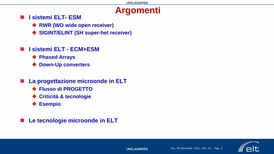
Argomenti I sistemi ELT- ESM
RWR (WO wide open receiver)
SIGINT/ELINT (SH super-het receiver)
I sistemi ELT - ECM+ESM
Phased Arrays
Down-Up converters
La progettazione microonde in ELT
Flusso di PROGETTO
Criticità & tecnologie
Esempio
Le tecnologie microonde in ELT

UNCLASSIFIED
UNCLASSIFIED Doc. 05 December 2011– Rev. 01 - Pag. 5
threat
emissions
on board emissions off board emissions
Wide Open
Receiver RF-FE control
E.M. environment control
DIG DATA
RF
Processor
RWR & HPOI - SURVEILLANCE
• Full instantaneous band
• Instantaneous Inhibition on the
interfering signal (CW)
• Fast response time
• Medium sensitivity −60 dBm
• AOA of mainbeam (up to HADF*)
• Emission analysis, mode
determination
• Emitter identification
RF front end Missions requirements:
• threat alarm & avoidance, even in partially
unknown scenario
• Surveillance, aid to situation awareness
• Electronic Reconnaissance
• ECM designation (if any)
• Emitter recording
Platforms: naval, airborne (large/medium body, tactical A/C), ground station & mobile vehicle
Missions: patrolling, coastal surveillance, SAR (mainly utility helo & cargo), light combat
t
f
DF=IBW DF =Frequency coverage
IBW=Instantaneous Band-Width
Receiver architecture vs E.M. scenario and mission:
Wide Open Rx (ESM/RWR)
*HADF, High Accuracy Direction Finding better than 1-2° RMS
UNCLASSIFIED
UNCLASSIFIED Doc. 05 December 2011– Rev. 01 - Pag. 6
SAM 1
SAM 2
AA
A 1
AAA3
SAM4
SAM3
AAA 2
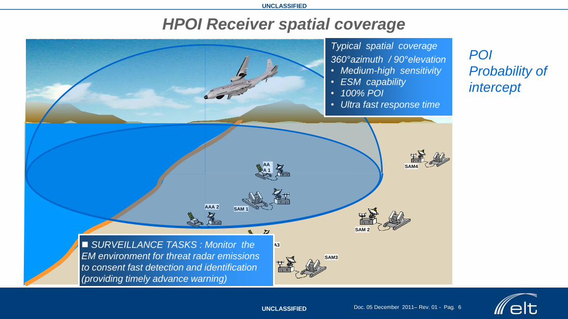
Typical spatial coverage
360°azimuth / 90°elevation
• Medium-high sensitivity
• ESM capability
• 100% POI
• Ultra fast response time
SURVEILLANCE TASKS : Monitor the
EM environment for threat radar emissions
to consent fast detection and identification
(providing timely advance warning)
HPOI Receiver spatial coverage
POI
Probability of
intercept

UNCLASSIFIED
UNCLASSIFIED Doc. 05 December 2011– Rev. 01 - Pag. 7
The EW analogue RX is typically based on an single-channel IFM (Instantaneous frequency measurement)
receiver with a multi- channel crystal video-envelope detector providing Amplitude monopulse Direction finding
Input RF,
from omni
antenna
frequency
value
delay line
RF
LO
video mixer
splitter
“ Hard limiter”
Analogue to digital
converter
Amplitude
Angle of
Arrival ,
PW,TOA
Fully open in
time,
frequency
and space
domains
Relatively poor sensitivity
Cannot sort simultaneous
signals
Simple,
(relatively) inexpensive,
instantaneous,
High Probability of
Intercept (POI) in
frequency range
Detector
Analogue to digital
converter
amplitude
value 1
Input RF,
from directive
antenna 1
RF video
“IFM RX”
“Crystal video RX”
“WIDE OPEN RX”
The WO analogue receiver: full band IFM Rx plus AM Crystal Video Rx
Detector
Analogue to digital
converter
amplitude
value N
Input RF,
from directive
antenna N
RF video Poor sensitivity and
simultaneous signal
performance
Special design for CW is
required

UNCLASSIFIED
UNCLASSIFIED Doc. 05 December 2011– Rev. 01 - Pag. 8
HIGH PERFORMANCE ESM & ELINT
threat
emissions on board emissions
off board emissions
Wide Band SH
Multichannel
DRX
RF front end &
distributor
Strategy of scanning
Dig. data
RF
Processor
• Wide instantaneous band RX
• Real time adaptive tuning on the
required band (fine analysis, threat
warning, search strategy)
• High sensitivity, -80/90 dBm
• HADF (typ 1°/2°)
• Accurate measurement of signal
parameters and Specific Emitter
Identification (fingerprinting)
Missions requirements:
• threat alarm & avoidance, on pre-mission data
• Electronic Reconnaissance
• Emitter fast and accurate geo-location
• Real time ELINT analysis
• Collection of intelligence data/ Emitter data
recording
• ECM designation (if any)
Platform & mission : ELINT/SIGINT naval, airborne
(large/medium body) and ground fixed-mobile stations
RF-FE control
DF
t
f
IBW
Ttuning
Receiver architecture vs E.M. scenario and mission:
Wide Band SH DRX (ESM/ELINT)

UNCLASSIFIED
UNCLASSIFIED Doc. 05 December 2011– Rev. 01 - Pag. 9
9
SAM 1 SAM 2
AAA 1 SAM4
AAA 2
Digital RX - Elint coverage
• Very high sensitivity
• SEI capability
• LPI detection
• Emitter location
SAM 1 SAM 2
AAA 1 SAM4
AAA 2
AAA3
SAM3
3 ELINT TASKS: Monitor the
EM environment for emitter
detection, identification, high
accuracy analysis (both
IntraPulse and InterPulse),
fingerprinting, rapid location
SH Digital Receiver spatial coverage

UNCLASSIFIED
UNCLASSIFIED Doc. 05 December 2011– Rev. 01 - Pag. 10
Frequency
RF input
RF bandwidth (RF coverage)
2GHz 18GHz
IF bandwidth
Input RF, from
antenna
RF frequency
RF amplitude,
angle of arrival,
pulse width,
time of arrival
modulation on pulse
mixer
“Superhet (NB/WB) Dig Rec”
The superheterodyne receiver uses frequency mixing to convert a received BW of signal to a fixed lower
frequency bandwidth, which can be conveniently sampled and processed using fully digital techniques
RF IF filter RF filter
LO
(variable frequency)
signal
digitizer DSP
The “Superhet” narrow/wide band digital receiver
0,5-1,0GHz
UNCLASSIFIED
UNCLASSIFIED Doc. 05 December 2011– Rev. 01 - Pag. 11
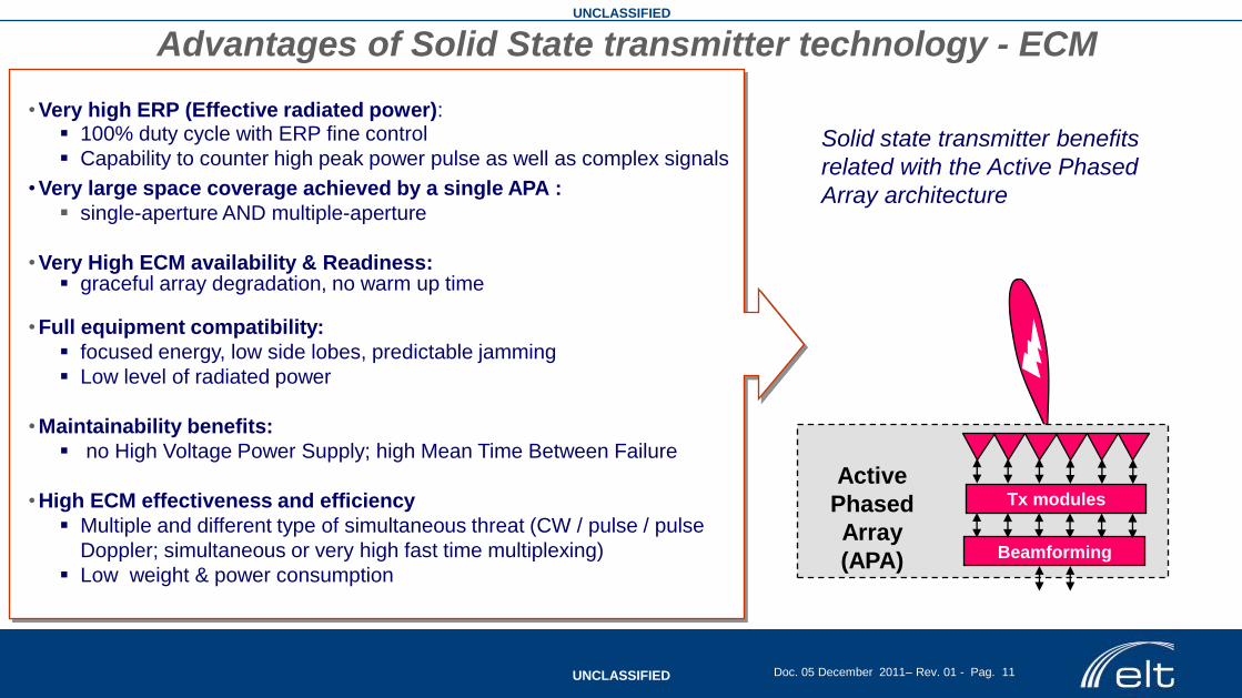
• Very high ERP (Effective radiated power): 100% duty cycle with ERP fine control
Capability to counter high peak power pulse as well as complex signals
• Very large space coverage achieved by a single APA :
single-aperture AND multiple-aperture
• Very High ECM availability & Readiness: graceful array degradation, no warm up time
• Full equipment compatibility:
focused energy, low side lobes, predictable jamming
Low level of radiated power
• Maintainability benefits:
no High Voltage Power Supply; high Mean Time Between Failure
• High ECM effectiveness and efficiency
Multiple and different type of simultaneous threat (CW / pulse / pulse
Doppler; simultaneous or very high fast time multiplexing)
Low weight & power consumption
Solid state transmitter benefits
related with the Active Phased
Array architecture
Advantages of Solid State transmitter technology - ECM
Tx modules
Beamforming
Active
Phased
Array
(APA)
UNCLASSIFIED
UNCLASSIFIED Doc. 05 December 2011– Rev. 01 - Pag. 12
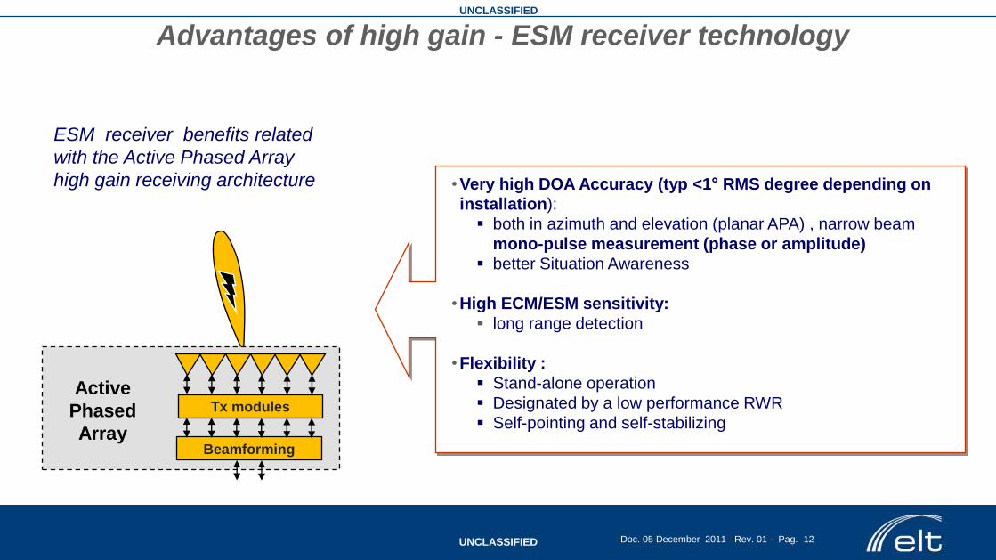
ESM receiver benefits related
with the Active Phased Array
high gain receiving architecture • Very high DOA Accuracy (typ <1° RMS degree depending on
installation):
both in azimuth and elevation (planar APA) , narrow beam
mono-pulse measurement (phase or amplitude)
better Situation Awareness
• High ECM/ESM sensitivity:
long range detection
• Flexibility :
Stand-alone operation
Designated by a low performance RWR
Self-pointing and self-stabilizing
Advantages of high gain - ESM receiver technology
Tx modules
Beamforming
Active
Phased
Array
UNCLASSIFIED
UNCLASSIFIED Doc. 05 December 2011– Rev. 01 - Pag. 13
to/from
SH ch.
(D.U.C.)
Serial Link
Mode
Selection
TX RX Module
8 W
ay D
iv / C
om
b
Array Control
Beam
Forming
Network
TX RX Module
TX RX Module
TX RX Module
TX RX Module
TX RX Module
TX RX Module
TX RX Module
TX RX Module
TX RX Module
TX RX Module
TX RX Module
TX RX Module
TX RX Module
TX RX Module
TX RX Module
8 W
ay D
iv / C
om
b
Low Voltages
to internal modules
Command to
modules
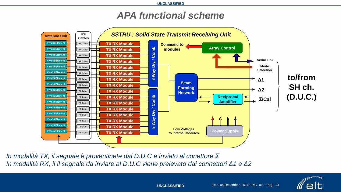
SSTRU : Solid State Transmit Receiving Unit
Power Supply
Σ/Cal
Δ1
Δ2
RF Cable
RF Cable
RF Cable
RF Cable
RF Cable
RF Cable
RF Cable
RF Cable
RF Cable
RF Cable
RF Cable
RF Cable
RF Cable
RF Cable
RF Cable
RF Cable
RF
Cables
AAU
Vivaldi Element
Antenna Unit
APA functional scheme
Reciprocal
Amplifier
Vivaldi Element
Vivaldi Element
Vivaldi Element
Vivaldi Element
Vivaldi Element
Vivaldi Element
Vivaldi Element
Vivaldi Element
Vivaldi Element
Vivaldi Element
Vivaldi Element
Vivaldi Element
Vivaldi Element
Vivaldi Element
Vivaldi Element
In modalità TX, il segnale è proventinete dal D.U.C e inviato al conettore Σ
In modalità RX, il il segnale da inviare al D.U.C viene prelevato dai connettori Δ1 e Δ2
UNCLASSIFIED
UNCLASSIFIED Doc. 05 December 2011– Rev. 01 - Pag. 14
Frequency RF input
RF bandwidth (ECM -RF coverage)
6GHz 18GHz
IF bandwidth
0.5-1,0GHz
Input RF from APA
(Δ1 or Δ2)
down
Output RF
To APA
(Σ)
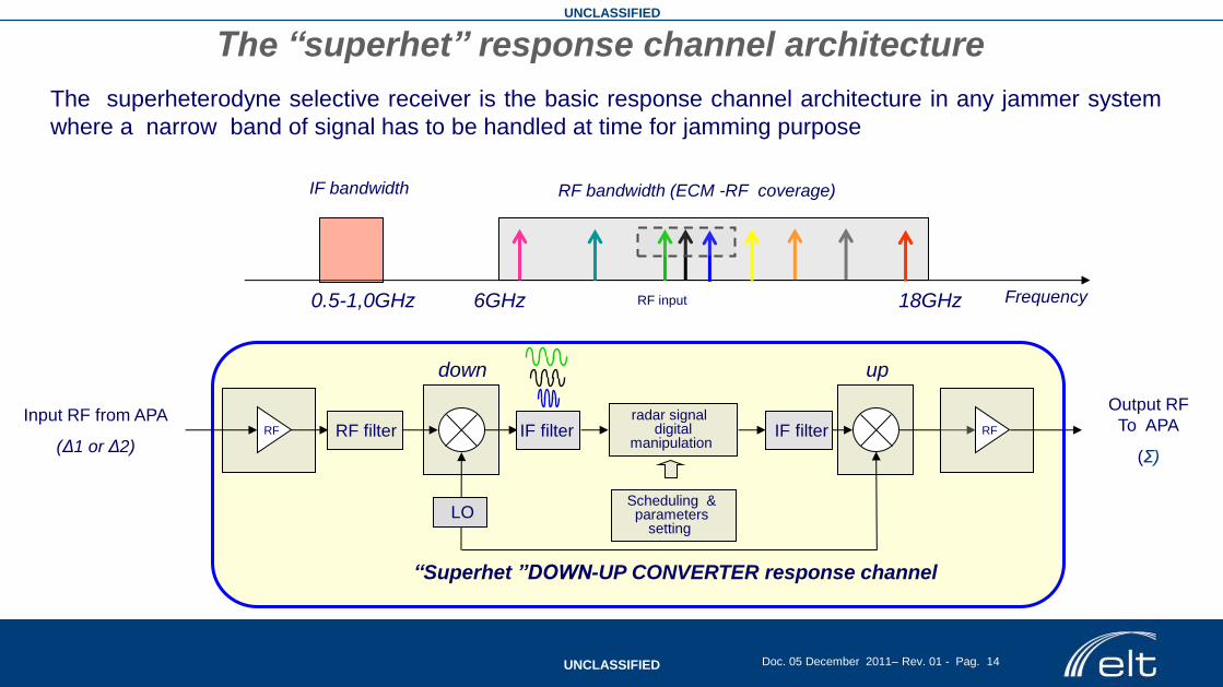
“Superhet ”DOWN-UP CONVERTER response channel
RF IF filter RF filter radar signal
digital manipulation
The superheterodyne selective receiver is the basic response channel architecture in any jammer system
where a narrow band of signal has to be handled at time for jamming purpose
up
IF filter
Scheduling & parameters
setting LO
The “superhet” response channel architecture
RF

UNCLASSIFIED
UNCLASSIFIED Doc. 05 December 2011– Rev. 01 - Pag. 15
PROGETTAZIONE MW ELT
Flusso di PROGETTO
Principali criticità & tecnologie
Esempio di progetto HW

UNCLASSIFIED
UNCLASSIFIED Doc. 05 December 2011– Rev. 01 - Pag. 16
Feasibility & Specification
Design And Simulation
Manufacturing &
Testing
Library
HW Design Flow
Know how
HW Documentation
Mechanical Engineering
Design of new Components

UNCLASSIFIED
UNCLASSIFIED Doc. 05 December 2011– Rev. 01 - Pag. 17
Microwave Technologies:
GaAs Monolithic microwave circuits (ELT
design)
GaN on SiC Monolithic microwave circuits
Multilayer video/digital circuits
Thin Film on alumina and teflon glass
substrates
Assembling processes
M.M.C.M (Microwave Multi -Chip Module)
Critical Design Constraints:
High levels of HW integration
(RF&Digital)
Time To Market
Thermal and mechanical issues
Technological upgrading
Integration in company internal design
flow
UNCLASSIFIED
UNCLASSIFIED Doc. 05 December 2011– Rev. 01 - Pag. 18
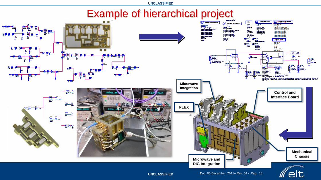
Example of hierarchical project
Microwave
Integration
FLEX
Control and
Interface Board
Microwave and
DIG Integration
Mechanical
Chassis
UNCLASSIFIED
UNCLASSIFIED Doc. 05 December 2011– Rev. 01 - Pag. 19
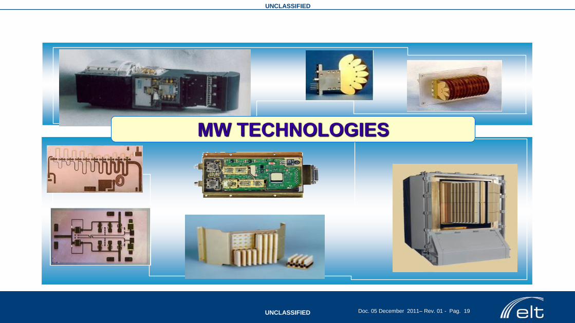
MW TECHNOLOGIES
UNCLASSIFIED
UNCLASSIFIED Doc. 05 December 2011– Rev. 01 - Pag. 20
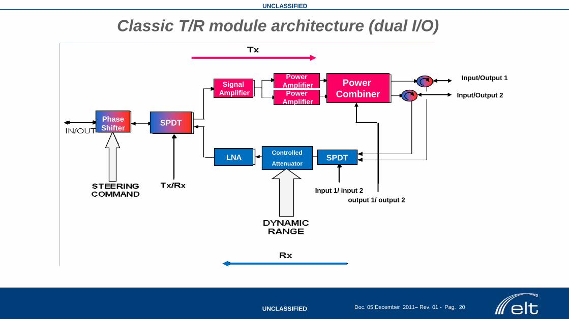
Input 1/ input 2
Input/Output 1
Input/Output 2
Phase shifter
Power
Combiner
Power
Amplifier Power
Amplifier
Signal
Amplifier
SPDT
SPDT
Phase
Shifter
LNA Controlled
Attenuator
output 1/ output 2
Classic T/R module architecture (dual I/O)
UNCLASSIFIED
UNCLASSIFIED Doc. 05 December 2011– Rev. 01 - Pag. 21
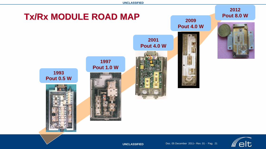
Tx/Rx MODULE ROAD MAP
1993
Pout 0.5 W
1997
Pout 1.0 W
2001
Pout 4.0 W
2009
Pout 4.0 W
2012
Pout 8.0 W
UNCLASSIFIED
UNCLASSIFIED Doc. 05 December 2011– Rev. 01 - Pag. 22
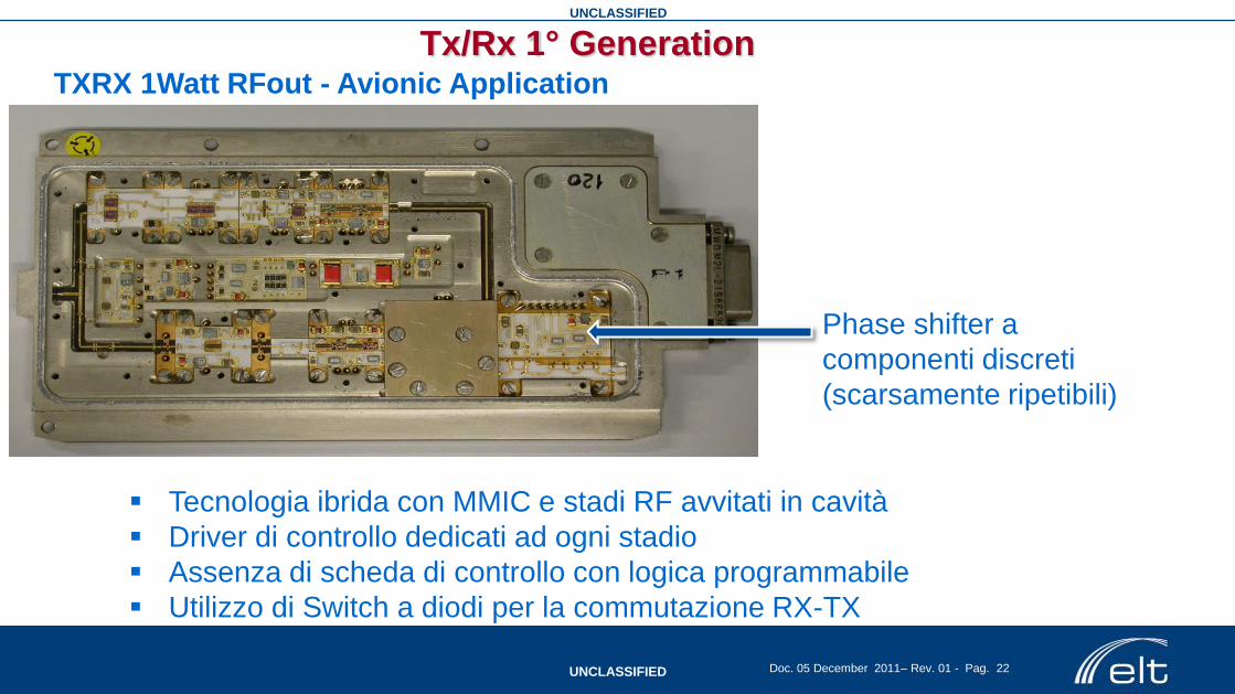
Tecnologia ibrida con MMIC e stadi RF avvitati in cavità
Driver di controllo dedicati ad ogni stadio
Assenza di scheda di controllo con logica programmabile
Utilizzo di Switch a diodi per la commutazione RX-TX
Phase shifter a
componenti discreti
(scarsamente ripetibili)
Tx/Rx 1° Generation TXRX 1Watt RFout - Avionic Application

UNCLASSIFIED
UNCLASSIFIED Doc. 05 December 2011– Rev. 01 - Pag. 23
Tecnologia con micro-package per alloggiare il Chipset di MMIC
2 Circolatori 6-18GHz per isolamento RX-TX e doppia polarizzazione
Phase Shifter in tecnologia MMIC
Impiego di un ASIC
per la scheda
controlli
TXRX 4Watt RFout - Naval Application
Tx/Rx 2° Generation

UNCLASSIFIED
UNCLASSIFIED Doc. 05 December 2011– Rev. 01 - Pag. 24
TXRX RFout - Avionic Application
Tecnologia con micro-package per alloggiare il Chipset di MMIC
Impiego del circolatore 6-18GHz per isolamento RX-TX
Scheda con logica programmabile e controllo in temperatura
PLD e E2Prom con DAC esterni
per la scheda controlli
Tx/Rx 2° Generation

UNCLASSIFIED
UNCLASSIFIED Doc. 05 December 2011– Rev. 01 - Pag. 25
• More than 30dB gain
• Hermetically sealed sub-assemblies • Cu20Mo80 heat spreaders
• Microstrip-stripline-microstrip for RF I/O
transitions
• Epoxy glued or brazed MMIC for best thermal
dissipation;
• Internal bypass capacitors
• Automatic assembling compatible
Multichip Packaging for
High Integration T/R Module

UNCLASSIFIED
UNCLASSIFIED Doc. 05 December 2011– Rev. 01 - Pag. 26
Multilayer Technology - RF and Digital circuit integrated on the same substrate.
First prototype
Tx / Rx – 3° generation of TR modules

UNCLASSIFIED
UNCLASSIFIED Doc. 05 December 2011– Rev. 01 - Pag. 27
Gallium Arsenide (GaAs) VS Gallium Nitride (GaN)
Parameter Unit SiC Si GaAs
(AlGaAs/InGaAs)
GaN
(AlGaN/GaN)
BandGap Energy eV 3.26 1.12 1.43 3.44
Electric breakdown
field MV/cm 3 0.3 0.4 3.0
Saturated (peak)
electrons velocity
x107
cm/s 2.0 (2.0) 1.0 (1.0) 1.0 (2.1) 2.5 (2.7)
Electron mobility cm2/V·s 700 1500 8500 1000-2000
Thermal conductivity W/cm·K 3.7 – 4.5 1.5 0.5 1.3 – 2.1
Relative permittivity - 10.1 11.8 12.8 9.0
UNCLASSIFIED
UNCLASSIFIED Doc. 05 December 2011– Rev. 01 - Pag. 28
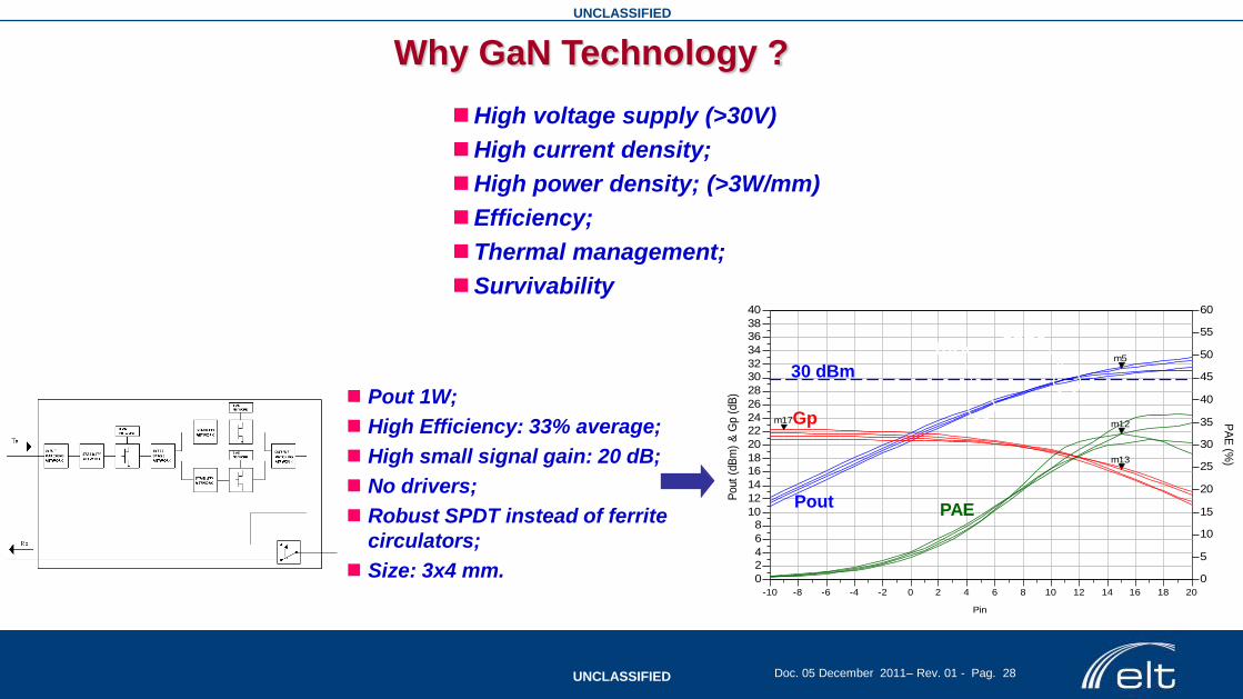
Why GaN Technology ?
High voltage supply (>30V)
High current density;
High power density; (>3W/mm)
Efficiency;
Thermal management;
Survivability
Pout 1W;
High Efficiency: 33% average;
High small signal gain: 20 dB;
No drivers;
Robust SPDT instead of ferrite
circulators;
Size: 3x4 mm. -8 -6 -4 -2 0 2 4 6 8 10 12 14 16 18-10 20
2
4
6
8
10
12
14
16
18
20
22
24
26
28
30
32
34
36
38
0
40
5
10
15
20
25
30
35
40
45
50
55
0
60
Pin
Pout
(dB
m)
& G
p (
dB
)
Readout
m5
Readout
m13
Readout
m17 PA
E (%
)
Readout
m12
m5indep(m5)=plot_vs(Pout_dBmPA[1],Pin)=31.41freqRF=10.000000
15.00 m12Pin=PAE_10GHz=32.53 / 0.00
15.00
m13Pin=Gp_10GHz=16.41
15.00m17Pin=Gp_10GHz=22.30
-9.00
PAE Pout
Gp
1dBc 3dBc
30 dBm

UNCLASSIFIED
UNCLASSIFIED Doc. 05 December 2011– Rev. 01 - Pag. 29
Divider (x4)
Divider (x4)
RF Channel
RF Channel
RF Channel
RF Channel
RF Channel
RF Channel
RF Channel
RF Channel
Control Board
8 T/R
joined
together
Innovation and applications of GaN - 4° generation of TR modules
VS
…x8…
MMIC Size reduction: 60 %
Cost reduction: 60 %
Efficiency increase: 90 %
Cooling system lighter
Losses reduction versus antennas
T/R modules
UNCLASSIFIED
UNCLASSIFIED Doc. 05 December 2011– Rev. 01 - Pag. 30
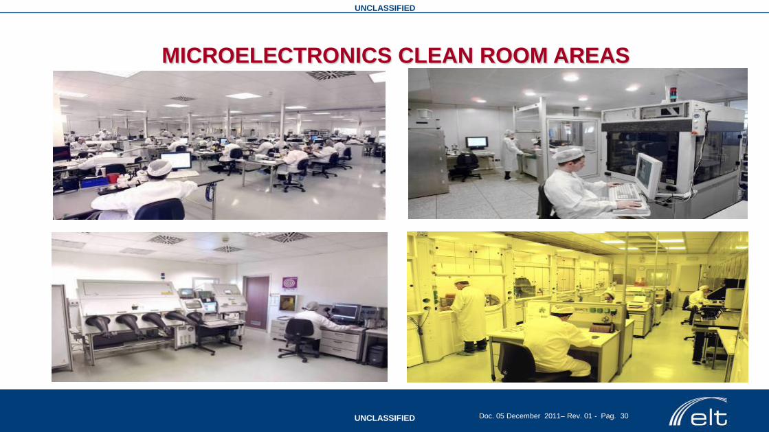
MICROELECTRONICS CLEAN ROOM AREAS
UNCLASSIFIED
UNCLASSIFIED Doc. 05 December 2011– Rev. 01 - Pag. 31
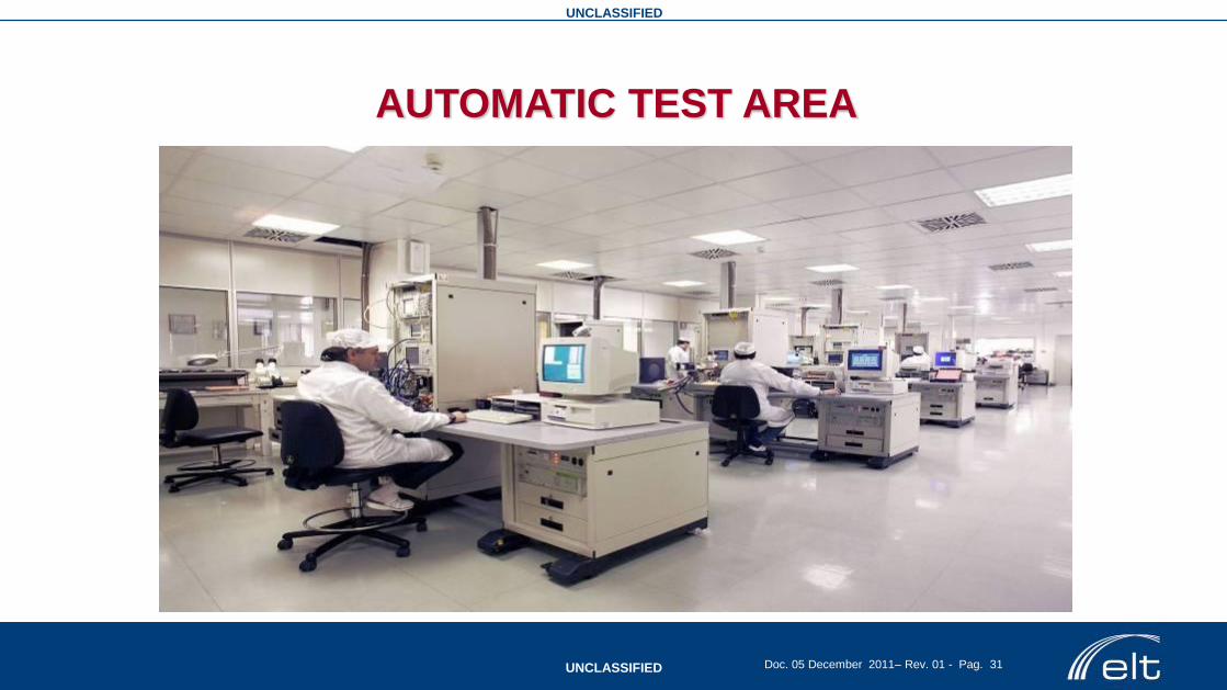
AUTOMATIC TEST AREA
UNCLASSIFIED
UNCLASSIFIED Doc. 05 December 2011– Rev. 01 - Pag. 32
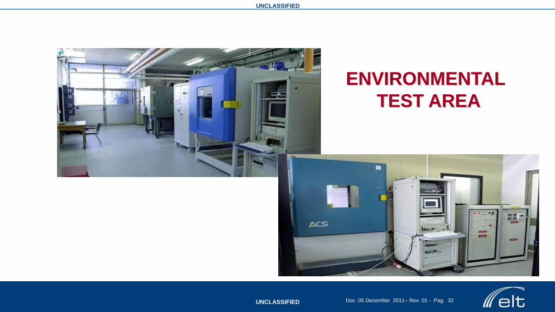
ENVIRONMENTAL
TEST AREA

UNCLASSIFIED
UNCLASSIFIED Doc. 05 December 2011– Rev. 01 - Pag. 33
www.elt-roma.com
Letture di riferimento
• Microwave Receivers With Electronic Warfare Applications, James Tsui, WILEY
• Integrated Microwave Front-Ends with Avionics Applications, Leo G. Maloratsky, ARTECH HOUSE RADAR LIBRARY
• Fundamentals of Electronic Warfare, Sergei A. Vakin, Lev N. Shustov, Robert H. Dunwell, ARTECH HOUSE RADAR LIBRARY
• EW 101: A First Course in Electronic Warfare, David L. Adamy, ARTECH HOUSE RADAR LIBRARY
• EW 102: A Second Course in Electronic Warfare, David L. Adamy, ARTECH HOUSE RADAR LIBRARY
• EW 103: Tactical Battlefield Communications Electronic Warfare, David L. Adamy, ARTECH HOUSE RADAR LIBRARY


