
Model 3150 DownflowService Manual
IMPORTANT: Fill in Pertinent Information on Page 3 for Future Reference

Job Specification Sheet.......................................................................................................................................... 3General Commercial Pre-Installation Check List.................................................................................................... 43200 Timer Setting Procedure................................................................................................................................ 53200 & 3210 Timer Series Regeneration Cycle Program Setting Procedure......................................................... 6Commercial Demand Regeneration Control Timer Settings.................................................................................. 73210 Timer Assembly............................................................................................................................................. 83210 Timer Assembly Parts List............................................................................................................................. 9Control Valve Assembly........................................................................................................................................ 10Control Valve Assembly Parts List.........................................................................................................................11Control Drive Assembly........................................................................................................................................ 12Control Drive Assembly Parts List........................................................................................................................ 131800 Series Brine System Assembly................................................................................................................... 141800 Series Brine System Assembly Parts List................................................................................................... 152” Brass Meter Assembly & Parts List.................................................................................................................. 16Service Valve Operator Assembly & Parts List..................................................................................................... 17Service Assemblies.............................................................................................................................................. 18Troubleshooting.................................................................................................................................................... 19General Service Hints for Meter Control.............................................................................................................. 20Water Conditioner Flow Diagrams........................................................................................................................ 21Flow Data & Injector Draw Rates......................................................................................................................... 23Typical Timer Settings.......................................................................................................................................... 24Installation Drawings............................................................................................................................................ 25System #4 Immediate/Delayed Regeneration Valve Wiring................................................................................. 27System #4 - Remote Signal Start Valve Wiring.................................................................................................... 28System #5 - Duplex Valve Wiring......................................................................................................................... 29System #6 - Duplex Valve Wiring......................................................................................................................... 30System #7 - Duplex 24V/120V 3-Way Valve Wiring............................................................................................. 31System #7 - Duplex 230V 3-Way Valve Wiring.................................................................................................... 32
Table of Contents
IMPORTANT: The information, specifications and illustrations in this manual are based on the latest information available at the time of printing. The manufacturer reserves the right to make changes at any time without notice.

Job.No..
Model No.
Water Test
Capacity Per Unit
Mineral Tank Size Diameter Height
Brine Tank Size & Salt Setting per Regeneration
Control Valve Specifications
1. Type of Timer
A. 7 Day or 12 Day
B. 1,250 to 21,250 Gallon Meter or
6,250 to 106,250 Gallon Meter or
Other C. Meter Wiring Package
1. System #4 - 1 Tank, 1 Meter, Immediate or Delayed Regeneration
2. System #5 - 2 Tanks, 2 Meters, Interlock
3. System #6 - 2 Tanks, 1 Meter, Series Regeneration
4. System #7 - 2 Tanks, 1 Meter, Alternator
2. Timer Program Settings
A. Backwash Minutes
B. Brine & Slow Rinse Minutes
C. Rapid Rinse Minutes
D. Brine Tank Refill Minutes
3. Drain Line Flow Control gpm
4. Brine Line Flow Controller gpm
5. Injector Size #
6. Service Valve Operation Units (SVO)
Size of Service Valve
Page 3
Job Specification Sheet

Page 4
General Commercial Pre-Installation Check List
WATER PRESSURE: A minimum of 25 pounds of water pressure is required for regeneration valve to operate effectively.
ELECTRICAL FACILITIES: A continuous 115 volt, 60 Hertz current supply is required. (Other voltages available.) Make certain the current supply is always hot and cannot be turned off with another switch.
EXISTING PLUMBING: Condition of existing plumbing should be free from lime and iron buildup. Piping that is built up heavily with lime and/or iron should be replaced. If piping is clogged with iron, a separate iron filter unit should be installed ahead of the water softener.
LOCATION OF SOFTENER AND DRAIN: The softener should be located close to a drain.
BY-PASS VALVES: Always provide for the installation of a by-pass valve.
CAUTION: Water pressure is not to exceed 120 p.s.i., water temperature is not to exceed 100°F, and the unit can-not be subjected to freezing conditions.
INSTALLATION INSTRUCTIONS1. Place the softener tank where you want to install the unit making sure the unit is level and on a firm base. (Maximum 7 feet apart for twin units.)
2. All plumbing should be done in accordance with local plumbing codes. The pipe size for the drain line should be the same size as the drain line flow control connection. Water meters are to be installed on soft water outlets. Twin units with (1) one meter shall be installed on common soft water outlet of units.
3. Make sure that the floor is clean beneath the salt storage tank and that it is level.
4. Place approximately 1” of water above the grid plate (if used) in your salt tank Salt may be placed in the unit at this time.
5. Place in by-pass position. Turn on the main water supply. Open a cold soft water tap nearby and let run a few minutes or until the system is free from foreign material (usually solder) that may have resulted from the installation.
6. Place the by-pass in service position.
7. Manually index the softener control into “service” position and let water flow into the mineral tank. When water flow stops, close inlet valve, place control in “backwash” position to relieve head of air, then gradually open inlet valve to purge remaining air in tank. Return control to “service” position.
8. Electrical: All electrical connections must be connected according to codes. Use electrical conduit if applicable. Plug into power supply.

Page 5
3200 Timer Setting Procedure
How To Set Days On Which Water Conditioner Is To Regenerate:Rotate the skipper wheel until the number “1” is at the red pointer. Set the days that regeneration is to occur by sliding tabs on the skipper wheel outward to expose trip fingers. Each tab is one day. Finger at red pointer is tonight. Moving clockwise from the red pointer, extend or retract fingers to obtain the desired regeneration sched-ule.
How To Set The Time Of Day:1. Press and hold the red button in to disengage the drive gear.2. Turn the large gear until the actual time of day is at the time of day pointer.3. Release the red button to again engage the drive gear.
How To Manually Regenerate Your Water Conditioner At Any Time:1. Turn the manual regeneration knob clockwise.2. This slight movement of the manual regeneration knob engages the program wheel and starts the regeneration program.3. The black center knob will make one revolution in the following approximately three hours and stop in the position shown in the drawing.4. Even though it takes three hours for this center knob to complete one revolution, the regeneration cycle of your unit might be set only one half of this time.5. In any event, conditioned water may be drawn after rinse water stops flowing from the water conditioner drain line.
How to Adjust Regeneration Time:1. Disconnect the power source.2. Locate the three screws behind the manual regeneration knob by pushing the red button in and rotating the 24 hour dial until each screw appears in the cut out portion of the manual regeneration knob.3. Loosen each screw slightly to release the pressure on the time plate from the 24 hour gear.4. Locate the regeneration time pointer on the inside of the 24 hour dial in the cut out.5. Turn the time plate so the desired regeneration time aligns next to the raised arrow.6. Push the red button in and rotate the 24 hour dial. Tighten each of the three screws.7. Push the red button and locate the pointer one more time to ensure the desired regeneration time is correct.8. Reset the time of day and restore power to the unit.

Page 6
3200 & 3210 Timer SeriesRegeneration Cycle Program Setting Procedure
How To Set The Regeneration Cycle Program:The regeneration cycle program on your water condi-tioner has been factory preset, however, portions of the cycle or program may be lengthened or shortened in time to suit local conditions.
3200 & 3210 Series Timers (Figure to Right)To expose cycle program wheel, grasp timer in upper left-hand corner and pull, releasing snap retainer and swinging timer to the right.To change the regeneration cycle program, the program wheel must be removed. Grasp program wheel and squeeze protruding lugs toward cen-ter, lift program wheel off timer. (Switch arms may require movement to facilitate removal)Return timer to closed position engaging snap retainer in back plate. Make certain all electrical wires locate above snap retainer post.
Timer Setting Procedure for the 3200 & 3210 Timers
How To Change The Length Of The Backwash Time:The program wheel as shown in the drawing is in the service position. As you look at the numbered side of the program wheel, the group of pins starting at zero determines the length of time your unit will backwash.
EXAMPLE: If there are six pins in this section, the time of backwash will be 12 min. (2 min. per pin). To change the length of backwash time, add or remove pins as required. The number of pins times two equals the backwash time in minutes.
How To Change The Length Of Brine And Rinse Time:
The group of holes between the last pin in the backwash section and the second group of pins determines the length of time that your unit will brine and rinse (2 min. per hole.)To change the length of brine and rinse time, move the rapid rinse group of pins to give more or fewer holes in the brine and rinse section. Number of holes times two equals brine and rinse time in minutes.
1.
2.
3.
1.
2.
How To Change The Length Of Rapid Rinse:The second group of pins on the program wheel determines the length of time that your water condi-tioner will rapid rinse. (2 min. per pin.)To change the length of rapid rinse time, add or remove pins at the higher numbered end of this section as required. The number of pins times two equals the rapid rinse time in minutes.
How To Change The Length Of Brine Tank Refill Time:
The second group of holes in the program wheel determines the length of time that your water condi-tioner will refill the brine tank (2 min. per hole.)To change the length of refill time, move the two pins at the end of the second group of holes as required.The regeneration cycle is complete when the outer microswitch is tripped by the two pin set at end of the brine tank refill section.The program wheel, however, will continue to rotate until the inner micro-switch drops into the notch on the program wheel.
1.
2.
1.
2.
3.
4.

Page 7
Commercial Demand Regeneration Control Timer Settings
Typical Programming ProcedureCalculate the gallon capacity of the system, subtract the necessary reserve requirement and set the gallons available opposite the small white dot on the program wheel gear.
NOTE: Drawing shows 8,750 gallon setting. The capacity (gallons) arrow denotes remaining gallons exclusive of fixed reserve.
How To Set The Time Of Day:Press and hold the red button in to disengage the drive gear.Turn the large gear until the actual time of day is opposite the time of day pointer.Release the red button to again engage the drive gear.
1.
2.
3.
How To Manually Regenerate Your Water Condi-tioner At Any Time:
Turn the manual regeneration knob clockwise.This slight movement of the manual regeneration knob engages the program wheel and starts the regeneration program.The black center knob will make one revolution in the following approximately three hours and stop in the position shown in the drawing.Even though it takes three hours for this center knob to complete one revolution, the regeneration cycle of your unit might be set for only one half of this time.In any event, conditioned water may be drawn after rinse water stops flowing from the water conditioner drain line.
Immediate Regeneration Timers:These timers do not have a 24 hour gear. Setting the gallons on the program wheel and manual regeneration procedure are the same as previous instructions.
1.2.
3.
4.
5.
NOTE: To set meter capacity rotate manual knob one - 360° revolution to set gallonage.

Page 8
3210 Timer Assembly

Page �
3210 Timer Assembly Parts List
Item No. Quantity Part No. Description. 1.................... 1..................... 13870-01.............. Housing Assy, Timer, 3210. 2.................... 1..................... 13802................... Gear, Cycle Actuator. 3.................... 1..................... 400�6-xx.............. 24 Hour Gear Assy, 12 Midnight 400�6-02.............. Dial 2 AM Regen Assy, Black. 5.................... 1..................... 13886................... Knob, 3200. 6.................... 4..................... 13296................... Screw, Hex Wsh, 6-20 x 1/2. 7.................... 2..................... 11999................... Label, Button. 8.................... 1..................... 60405-50.............. Program Wheel Assy, w/2” Std Label Set @ 21. 9.................... 1..................... 13806................... Retainer, Program Wheel. 10.................. 1..................... 13748................... Screw, Flt Hd St, 6-20 x 1/2. 11.................. 1..................... 14265................... Clip, Spring. 12.................. 1..................... 15424................... Spring, Detent, Timer. 13.................. 1..................... 15066................... Ball, 1/4” Delrin. 14.................. 1..................... 13911................... Gear, Main Drive, Timer. 15.................. 1..................... 19210................... Program Wheel Assy. 16.................. 21................... 15493................... Pin, Spring, 1/16 x 5/8 SS. 18.................. 1..................... 13018................... Pinion, Idler. 19.................. 1..................... 13312................... Spring, Idler Shaft. 20.................. 1..................... 13017................... Gear, Idler. 21.................. 1..................... 13164................... Gear, Drive. 23.................. 1..................... 13887................... Plate, Motor Mounting. 24.................. 1..................... 18743................... Motor, 120V, 60 Hz 1/30 RPM, 5600 1�65�-1................ Motor, 24V, 60 Hz 1/30 RPM. 25.................. 2..................... 13278................... Screw, Phil Hd Mach, 6-32 x 1/8. 26.................. 1..................... 13830................... Pinion, Program Wheel Drive. 27.................. 1..................... 13831................... Clutch, Drive Pinion. 28.................. 1..................... 14276................... Spring, Meter Clutch. 29.................. 1..................... 14253................... Retainer, Clutch Spring. 31.................. 3..................... 11384................... Screw, Phil, 6-32 x 1/4. 32.................. 1..................... 13881................... Bracket, Hinge Timer. 33.................. 3..................... 14087................... Insulator. 34.................. 1..................... 10896................... Switch, Micro. 35.................. 1..................... 15320................... Switch, Micro, Timer. 36.................. 2..................... 11413................... Screw, Pan Hd Mach, 4-40 x 1 1/8. 37.................. 1..................... 14007................... Label, Time of Day. 38.................. 1..................... 14045................... Label, Instruction Not Shown.... 1..................... 13902................... Harness, 3200 Not Shown.... 2..................... 40422................... Nut, Wire, Tan Not Shown.... 1..................... 15354-01.............. Wire, Ground, 4” Not Shown.... 1..................... 15465................... Caution Label Not Shown.... 1..................... 14198................... Capacity Label

Page 10
Control Valve Assembly

Page 11
Control Valve Assembly Parts List
Item No. Quantity Part No. Description. 1.................... 1..................... 15114.......................Valve Body, 3150. 2.................... 8..................... 11720.......................Seal, Piston, 2�00/3150. 3.................... 5..................... 10369.......................Spacer, 2”, 2�00/3150. . . 16141.......................Spacer, Port Ring. 4.................... 2..................... 10368.......................Spacer, Narrow, 3150/3�00 10368-01..................Spacer, Quad Ring, Brass. 5.................... 1..................... 16130.......................Piston, High Backwash 1�611-01..................Piston Assy, 3150, NHWBP, O-ring. 6.................... 1..................... 14818.......................Ring, Piston Rod, Snap. 7.................... 1..................... 15125.......................Rod, Piston, 3150. . . 19708.......................Rod, Piston, 3150 NHWBP. 8.................... 1..................... 14922.......................O-ring, -035, Piston. 9.................... 1..................... 163�8-01..................End Plug Assy, 3150, White. 10.................. 1..................... 15112.......................Seal, 3150 Adapter Base. 11.................. 1..................... 17407.......................Adapter, 3150, Sidemount. 12.................. 2..................... 40118.......................Screw, Sckt Hd, 1/2 - 13 Unc
Options. 13.................. 1..................... 15117-01..................Adapter, 3150, Machined. *14................ 1..................... 15247.......................O-ring, -22�. 15.................. 1..................... 13575.......................O-ring, -240. . . 15210.......................O-ring, -343, Park Tank. 16.................. 1..................... 1�608-20..................Disperser, Commercial, 2”, 3150 (Not Shown)
Options. 17.................. 1..................... 40365.......................Base, 3130/3150, Rotating. 18.................. 1..................... 40316.......................Adapter, Sidemount. 19.................. 1..................... 16804-01..................O-ring, -150. 20.................. 1..................... 40368.......................O-ring, -160, Sidemount, Flange. 21.................. 7..................... 19768.......................Screw, Hex Hd, 3/8 - 16 x 1, Cap 18-8. 22.................. 7..................... 40375.......................Washer, Flat, 3/8, Type A, N-sers
* Do not use this o-ring if control is side-mounted.

Page 12
Control Drive Assembly

Page 13
Control Drive Assembly Parts List
Item No. Quantity Part No. Description. .1....................1..................... 1�304-00................................Backplate, 3150/3�00 Upper, Env Sys #4, 5, 6, Lag, 3�00 Lead. .2....................1..................... 15120-01................................Bracket, Motor Mtg, 3150/3�00 Environmental. .3....................2..................... 16346......................................Nut, Hex, Jam, 5/16 - 18. .4....................1..................... 40392......................................Motor, Drive, 115V, 50/60 Hz, Sp. . . 40390......................................Motor, Drive, 220V, 50 Hz, Sp, Fam 3. . . 40391......................................Motor, Drive, 24V, 50/60 Hz, Sp Fam 3. .5....................1..................... 17797......................................Bracket, Switch Mounting, 3150/3�00. .6....................4..................... 10302...................................... Insulator, Limit Switch. .7....................3..................... 10218......................................Switch, Micro. .8....................1..................... 17845-03................................Pin, Hinge, 3150/3�00, Env. .9....................4..................... 11235......................................Nut, Hex, 1/4 -20, Mach Screw, Zinc. .10..................2..................... 13365......................................Washer, Lock, #4, External. .11..................2..................... 12624......................................Screw, Phil Pan, 40 x 1 1/2. .13..................1..................... 16053......................................Bracket, Brine Side. .14..................2..................... 40133......................................Screw, Pan Hd, 4-40 x 1/4. .15..................1..................... 15226-*...................................Terminal Block. .16..................2..................... 16052......................................Bushing, 3150/3�00. .17..................1..................... 16059......................................Washer, SS, .88, 3150/3�00. .18..................1..................... 16051......................................Ring, Retaining, Bowed. 19...................2..................... 10300......................................Screw, Slot Hex Wsh, 18-8 x 3/8. .21..................4..................... 10231......................................Screw, Slot Hex, 1/4 - 20 x 1/2. .22..................2..................... 17567......................................Screw, Hex Wsh Hd, 8 x 1/2. .23..................2..................... 12288......................................Washer, Lock, #8 Zinc Plated. .24..................1..................... 164�4-05................................Cam Assy, 3150/3�00 Upper Signal After Rapid Rinse 164�4-03................................Cam Assy, 3150/3�00 Signal After Brine Fill. .25..................4..................... 11224......................................Screw, Hex Hd, 5/16 - 18 x 5/8. .27..................1..................... 19813......................................Screw, Env Cover, 1/4 - 20 SHCS 28A................1..................... 1�277-020..............................Cover, 3150/3�00 Env, Black. .30..................1..................... 18745......................................Window, Cover, 2�00. .32..................4..................... 13296......................................Screw, Hex Wsh, 6-20 x 1/2. .33..................1..................... 16046......................................Gear, Drive. .34..................1..................... 16050......................................Ring, Retaining. .35..................1..................... 11774......................................Ring, Retaining. .36..................1..................... 16047......................................Link, Drive. .37..................1..................... 11709......................................Pin, Drive Link. .38..................1..................... 16048......................................Bearing, Drive Link. .39..................1..................... 11898......................................Clip, 3150/3�00. .40..................1..................... 16045......................................Pinion, Drive. .41..................1..................... 11381......................................Pin, Roll, 2�00/3�00. .42..................1..................... 11080......................................Screw, Flt Hd Mach, 8-32 x 3/8. .43..................3..................... 10872......................................Screw, Hex Wsh, 8-32 x 17/64 Not Shown.....1.....................................................................Timer Not Shown.....1..................... 40084-12................................Power Cord, 12’ US, Round, 120V Sys 5, 6, 7 & 2�00/ 3150/3�00 #4 Not Shown.....1..................... 17967......................................Fitting Assy, Liquid Tight, Blk Not Shown.....1..................... 40396......................................Harness, Drive, Environmental Not Shown.....1..................... 19691......................................Plug, .750 Dia, Recessed, Black Not Shown.....1..................... 19591......................................Plug, .8750 Hole, Recessed, Black Not Shown.....1..................... 16427-04................................Wire, Lead, 12”, White Not Shown.....1..................... 40396......................................Harness, Drive, Environmental Not Shown.....1..................... 14924......................................Strain Relief Heyco #1247 Not Shown.....1..................... 15513......................................Meter Cable, 17.5” Not Shown.....2..................... 15250......................................Label, Terminal Strip Not Shown.....1..................... 17470......................................Cable Guide Assy, 2850/3150 Not Shown.....1..................... 19856......................................Ring, Retaining
* Specify number of terminals

Page 14
1800 Series Brine System Assembly

Page 15
1800 Series Brine System Assembly Parts List
Item No. Quantity Part No. Description. 1.................... 1..................... 16340.......................Body, Injector, 1800 D/F. 2.................... 1..................... 15128-xx..................Injector Nozzle. 3.................... 1..................... 15127-xx..................Injector Throat. 4.................... 3..................... 15246.......................O-ring, -116. 5.................... 1..................... 16341-01..................Cap, Injector, 1800. 6.................... 8..................... 12473.......................Screw, Hex Wsh, 10-24 x 5/8. 7.................... 1..................... 16341-02..................Plug, Injector, 1800. 8.................... 1..................... 13303-01..................O-ring, -021, 560CD. 9.................... 1..................... 164�7-01..................Stem Assy, 1800, Brine Valve. 10.................. 1..................... 18713.......................Brine Valve Body, 1800. 11.................. 1..................... 11772.......................Spring, 3150 Brine Valve. 12.................. 1..................... 11774.......................Ring, Retaining. 13.................. 1..................... 164�8-01..................Stem Guide Assy, Brine. 14.................. 1..................... 16387.......................Plug, Pipe, 1/2” NPT. 15.................. 2..................... 18702.......................Fitting, Tube, 1/2 NPT 5/8. 16.................. 1..................... 18703.......................Tube, Brine, 5/8 OD Annealed. 17.................. 1..................... 6000�-00..................Air Check, #�00, Commercial Less Fittings 6000�-01..................Air Check, #�00, Commercial, HW Less Fittings Not Shown.... 1......................................................Flow Control (Specify Flow Rate)
Option Without Brine Valve. . . 1...............................16605.......... Retainer Plate. . . 1...............................19860.......... Fitting, Brine Valve, 1800 Delete: Items 9 through 16. Injector Throat 15127-04..................#4................ Green 15127-05..................#5................ Red 15127-06..................#6................ White 15127-07..................#7................ Blue 15127-08..................#8................ Yellow 15127-0�..................#�................ Violet 15127-10..................#10.............. Black
Injector Nozzle 15128-04..................#4................ Green 15128-05..................#5................ Red 15128-06..................#6................ White 15128-07..................#7................ Blue 15128-08..................#8................ Yellow 15128-0�..................#�................ Violet 15128-10..................#10.............. Black

Page 16
2” Brass Meter Assembly & Parts List
Item No. Quantity Part No. Description. 1.................... 1..................... 14456.......................Body, Meter, 2”. 2.................... 1..................... 15532.......................Seat, Impeller, Shaft, Hex. 3.................... 1..................... 15432.......................Shaft, Impeller, SS. 5.................... 1..................... 15374.......................Impeller Assy, 2” Meter. 6.................... 1..................... 13847.......................O-ring, -137, Std/560CD, Meter 7A................. 1..................... 15218.......................Meter Cap Assy 7B................. 1..................... 15237.......................Meter Cap Assy, Ext. 8.................... 4..................... 12112.......................Screw, Hex Hd Mach, 10-24 x 1/2. 9.................... 1..................... 14679.......................O-ring, -227 Meter. 10.................. 1..................... 14568.......................Fitting, Nipple, 2”. 11.................. 1..................... 14680.......................Flow Straightener. 12.................. 1..................... 14569.......................Nut, 2�00 Meter

Page 17
Service Valve Operator Assembly & Parts List
Item No. Quantity Part No. Description. 1.................... 1..................... 15074.......................Body, SVO. 2.................... 1..................... 16065.......................Piston & Stem, SVO. 3.................... 1..................... 10141.......................O-ring, -010. 4.................... 2..................... 14835.......................Seal, 3150. 5.................... 1..................... 14834.......................Spacer, Softwater Fill. 6.................... 1..................... 16509.......................Plug, End, SVO. 7.................... 1..................... 12977.......................O-ring, -015. 8.................... 1..................... 15965.......................Fitting, Bias. 9.................... 1..................... 10249.......................Spring, Brine Valve. 10.................. 1..................... 10250.......................Ring, Retaining. 11.................. 1..................... 164�8-02..................Stem Guide Assy, SVO. 12.................. 3..................... 10332.......................Fitting, Insert, 3/8. 13.................. 3..................... 10330.......................Fitting, Sleeve, 3/8 Celcon. 14.................. 3..................... 10329.......................Fitting, Tube, 3/8 Nut, Brass. 15.................. 1..................... 16503.......................Fitting, Elbow, �0 Deg. Not Shown.... 1..................... 16511.......................Tube, 3150, PVC, SVO

Page 18
Service Assemblies 60036-02 Brine Valve, 1800, Design 3
1......11772...........Spring, 3150 Brine Valve1......11774...........Ring, Retaining1......18713...........Brine Valve Body, 18001......164�7-01......Stem Assy, 1800 Brine Valve New Style1......164�8-01......Stem Guide Assy, Brine
60277-xx .....1800 Injector Assembly
4......12473...........Screw, Hex Wsh, 10-24 x 5/81......15127...........Injector Throat Assy1......15128-xx......Injector Nozzle - Specify Size2......15246...........O-ring, -1161......16340...........Body, Injector, 1800, D/F1......16341-01......Cap, Injector, 1800
60106-00 .....Piston Assy, 3900/3150 Std
1......14818...........Ring, Piston Rod, Snap1......14922...........O-ring, -035, Piston1......16130...........Piston, High Backwash1......15125...........Rod, Piston, 31501......163�8-01......End Plug Assy, 3150, White
60113-01 .....Piston Assy, 3150, NHWBP, D-Flow Conversion/Replacement
1......163�8-01......End Plug Assy, 3150, White1......1�611-01......Piston Assy, 3150, NHWBP, O-ring1......19708...........Rod, Piston, 3150 NHWBP1......14818...........Ring, Piston Rod, Snap
60131 ..........Seal & Spacer Kit 2930/3130/3150
2......10368...........Spacer, Narrow, 3150/3�005......10369...........Spacer, 2”, 2�00/31508......11720...........Seal, Piston, 2�00/3150
60057-01 .....Drive Assy, 3150, 120V, B/Fill 3900 Upper Sys #5 or Sys # 7
4......10302...........Insulator, Limit Switch3......10872...........Screw, Hex Wsh, 8-32 x 17/641......11080...........Screw, Flt Hd Mach, 8-32 x 3/83......10218...........Switch, Micro2......12660...........Nut, Hex, 10-24 SS2......17567...........Screw, Hex Wsh Hd, 8 x 1/21......15120...........Bracket, Motor Mtg, 3150/3�001......40392...........Motor, Drive, 115V, 50/60 Hz SP11......16052...........Bushing, 3150/3�001......17797...........Bracket, Switch Mounting 3150/3�002......12624...........Screw, Phil Pan, 40 x 1 1/2
60150-3150 ...SVO Assy, 3150
60393 ............Meter Assy, 2900, 2” Std
60394 ............Meter Assy, 2900, 2” Ext
Side Mount Adapter61414...................Adapter, Assy, Sdmnt, 3130/3150 Rotating61414NP...............Adapter Assy, Sdmnt, 3130/3150 Nickel Plated Rotating61414-20..............Adapter Assy, Sdmnt61414-20NP.........Adapter Assy, Sdmnt

Page 1�
Troubleshooting
Problem Cause Correction1. Water conditioner fails to regenerate.
A. Electrical service to unit has been interrupted
A. Assure permanent electrical service (check fuse, plug, pull chain, or switch)
B. Timer is defective. B. Replace timer.C. Power failure. C. Reset time of day.
2. Hard water. A. By-pass valve is open. A. Close by-pass valve.B. No salt is in brine tank. B. Add salt to brine tank and maintain
salt level above water level.C. Injector screen plugged. C. Clean injector screen.D. Insufficient water flowing into brine tank.
D. Check brine tank fill time and clean brine line flow control if plugged.
E. Hot water tank hardness. E. Repeated flushings of the hot water tank is required.
F. Leak at distributor tube. F. Make sure distributor tube is not cracked. Check O-ring and tube pilot.
G. Internal valve leak. G. Replace seals and spacers and/or piston.
3. Unit used too much salt. A. Improper salt setting. A. Check salt usage and salt setting.B. Excessive water in brine tank. B. See problem 7.
4. Loss of water pressure. A. Iron buildup in line to water conditioner.
A. Clean line to water conditioner.
B. Iron buildup in water condi-tioner.
B. Clean control and add mineral cleaner to mineral bed. Increase frequency of regeneration.
C. Inlet of control plugged due to foreign material broken loose from pipes by recent work done on plumbing system.
C. Remove piston and clean control.
5. Loss of mineral through drain line.
A. Air in water system. A. Assure that well system has proper air eliminator control. Check for dry well condition.
B. Improperly sized drain line flow control.
B. Check for proper drain rate.
6. Iron in conditioned water. A. Fouled mineral bed. A. Check backwash, brine draw, and brine tank fill. Increase frequency of re-generation. Increase backwash time.

Page 20
Troubleshooting
Problem Cause Correction7. Excessive water in brine tank.
A. Plugged drain line flow control. A. Clean flow control.B. Plugged injector system. B. Clean injector and screen.C. Timer not cycling. C. Replace timer.D. Foreign material in brine valve. D. Replace brine valve seat and clean
valve.E. Foreign material in brine line flow control.
E. Clean brine line flow control.
8. Softener fails to draw brine. A. Drain line flow control is plugged.
A. Clean drain line flow control.
B. Injector is plugged. B. Clean injectorC. Injector screen plugged. C. Clean screen.D. Line pressure is too low. D. Increase line pressure to 20 P.S.I.E. Internal control leak E. Change seals, spacers, and piston
assembly.F. Service adapter did not cycle. F. Check drive motor and switches.
�. Control cycles continuously. A. Misadjusted, broken, or shorted switch.
A. Determine if switch or timer is faulty and replace it, or replace complete power head.
10. Drain flows continuously. A. Valve is not programming cor-rectly.
A. Check timer program and positioning of control. Replace power head assem-bly if not positioning properly.
B. Foreign material in control. B. Remove power head assembly and inspect bore. Remove foreign material and check control in various regeneration positions.
C. Internal control leak. C. Replace seals and piston assembly.
General Service Hints For Meter Control
Problem: Softener delivers hard water
. Reason: Reserve capacity has been exceeded.
. Correction: Check salt dosage requirements and reset program wheel to provide additional reserve.
.
. Reason: Program wheel is not rotating with meter output.
. Correction: Pull cable out of meter cover and rotate manually. Program wheel must move without binding and clutch must give positive clicks when program wheel strikes regeneration stop. If it does not, replace timer.
. Reason: Meter is not measuring flow.
. Correction: Check meter with meter checker.

Page 21
Water Conditioner Flow Diagrams
1 Service Position
Hard water enters at valve inlet — flows through valve to the top of tank — down through mineral to the bottom distributor. Conditioned water flows to the valve, around the piston and out the outlet.
2 Backwash Position 3 Brine and Slow Rinse Position
Hard water enters at valve inlet — flows thorough valve to the bottom of tank — up through mineral to top of tank, around the piston and out the drain. Hard water is also available at valve outlet.
Hard water enters at valve inlet — flows through injec-tor nozzle and throat to draw brine from the brine tank — brine flows through valve to the top of tank — down thorough mineral to bottom distributor — back to the valve, around the piston and out the drain. Flow thor-ough injectors continues for slow rinse for remainder of cycle. Hard water is also available at valve outlet.

Page 22
Water Conditioner Flow Diagrams
4 Rapid Rinse Position
5 Brine Tank Refill Position
Hard water enters at valve inlet — flows thorough valve to the top of tank — down thorough mineral to bottom distributor — back to the valve, around the piston and out the drain. Hard water is also available at valve outlet.
Hard water enters at valve inlet — flows through nozzle and tthrough throat to brine valve to refill the brine tank. Conditioned water is also available at valve outlet during this cycle.
Page 23
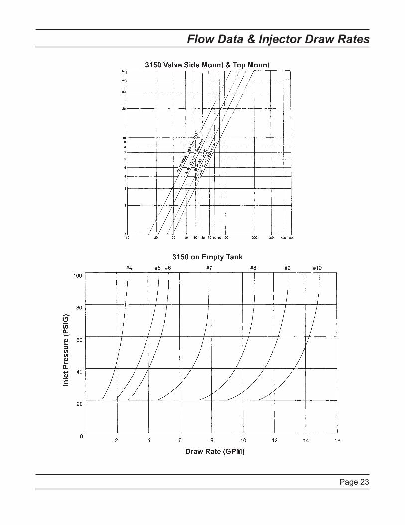
Flow Data & Injector Draw Rates

Page 24
Typical Timer Settings

Page 25
Installation Drawings
System #4 - Typical Single Tank Installation with Optional Meter
System #5 - Interlock - Typical Twin Tank Installation with Optional Meter Interlock and No Hard Water Bypass

Page 26
Installation Drawings
System #6 - Twin Series Regeneration Installation with a Remote Meter
System #7 - Twin Alternator Installation with a Remote Meter

Page 27
System #4 Immediate/Delayed Regeneration Valve Wiring
1866
�_R
EV
C

Page 28
System #4 - Remote Signal Start Valve Wiring
4050
0_R
EV
B

Page 2�
System #5 - Duplex Valve Wiring
186�0-01_REVD
186�0-02_REVD

Page 30
System #6 - Duplex Valve Wiring
18671-01_REVD
18671-02_REVD

Page 31
System #7 - Duplex 24V/120V 3-Way Valve Wiring
40503-01_REVB
40503-02_REVB

Page 32
System #7 - Duplex 230V 3-Way Valve Wiring
40504-01_REVB
40504-02_REVB

Page 33
Notes

Page 34
Notes

Page 35
Notes

P/N 16504 Rev. D 03/06


