Download - MP3 125 Workshop Manual
SERVICE STATION MANUAL633929(IT)-633930(EN)-633931(FR)-633932
(ES)-633937(ES)-633938(PT)-633941(NL)-633942(EL)
MP3 125

SERVICE STATIONMANUAL
MP3 125
The descriptions and illustrations given in this publication are not binding. While the basic features asdescribed and illustrated in this manual remain unchanged, PIAGGIO - GILERA reserves the right, atany time and without being required to update this publication beforehand, to make any changes to
components, parts or accessory supplies, which it considers necessary to improve the product or whichare required for manufacturing or construction reasons.
Not all versions shown in this publication are available in all Countries. The availability of individualversions should be confirmed with the official Piaggio sales network.
"© Copyright 2007 - PIAGGIO & C. S.p.A. Pontedera. All rights reserved. Reproduction of this publicationin whole or in part is prohibited."
PIAGGIO & C. S.p.A. - After-SalesV.le Rinaldo Piaggio, 23 - 56025 PONTEDERA (Pi)

SERVICE STATION MANUALMP3 125
This service station manual has been drawn up by Piaggio & C. Spa to be used by the workshops ofPiaggio-Gilera dealers. It is assumed that the user of this manual for maintaining and repairing Piaggiovehicles has a basic knowledge of mechanical principles and vehicle repair technique procedures. Anysignificant changes to vehicle characteristics or to specific repair operations will be communicated byupdates to this manual. Nevertheless, no mounting work can be satisfactory if the necessary equipmentand tools are unavailable. It is therefore advisable to read the sections of this manual relating to specialtools, along with the special tool catalogue.
N.B. Provides key information to make the procedure easier to understand and carry out.
CAUTION Refers to specific procedures to carry out for preventing damages to the vehicle.
WARNING Refers to specific procedures to carry out to prevent injuries to the repairer.
Personal safety Failure to completely observe these instructions will result in serious risk of personalinjury.
Safeguarding the environment Sections marked with this symbol indicate the correct use of the vehicleto prevent damaging the environment.
Vehicle intactness The incomplete or non-observance of these regulations leads to the risk of seriousdamage to the vehicle and sometimes even the invalidity of the guarantee.

INDEX OF TOPICS
CHARACTERISTICS CHAR
TOOLING TOOL
MAINTENANCE MAIN
TROUBLESHOOTING TROUBL
ELECTRICAL SYSTEM ELE SYS
ENGINE FROM VEHICLE ENG VE
ENGINE ENG
SUSPENSIONS SUSP
BRAKING SYSTEM BRAK SYS
COOLING SYSTEM COOL SYS
CHASSIS CHAS
PRE-DELIVERY PRE DE
TIME TIME


INDEX OF TOPICS
CHARACTERISTICS CHAR

This section describes the general specifications of the vehicle.
Rules
This section describes general safety rules for any maintenance operations performed on the vehicle.
Safety rules
- If work can only be done on the vehicle with the engine running, make sure that the premises are well-
ventilated, using special extractors if necessary; never let the engine run in an enclosed area. Exhaust
fumes are toxic.
- The battery electrolyte contains sulphuric acid. Protect your eyes, clothes and skin. Sulphuric acid is
highly corrosive; in the event of contact with your eyes or skin, rinse thoroughly with abundant water
and seek immediate medical attention.
- The battery produces hydrogen, a gas that can be highly explosive. Do not smoke and avoid sparks
or flames near the battery, especially when charging it.
- Fuel is highly flammable and it can be explosive given some conditions. Do not smoke in the working
area, and avoid open flames or sparks.
- Clean the brake pads in a well-ventilated area, directing the jet of compressed air in such a way that
you do not breathe in the dust produced by the wear of the friction material. Even though the latter
contains no asbestos, inhaling dust is harmful.
Maintenance rules
- Use original PIAGGIO spare parts and lubricants recommended by the Manufacturer. Non-original or
non-conforming spares may damage the vehicle.
- Use only the appropriate tools designed for this vehicle.
- Always use new gaskets, sealing rings and split pins upon refitting.
- After removal, clean the components using non-flammable or low flash-point solvent. Lubricate all the
work surfaces except the tapered couplings before refitting.
- After refitting, make sure that all the components have been installed correctly and work properly.
- For removal, overhaul and refit operations use only tools with metric measures. Metric bolts, nuts and
screws are not interchangeable with coupling members with English measurement. Using unsuitable
coupling members and tools may damage the scooter.
- When carrying out maintenance operations on the vehicle that involve the electrical system, make
sure the electric connections have been made properly, particularly the ground and battery connections.
Characteristics MP3 125
CHAR - 2

Vehicle identification
Chassis prefix (FULL OPTIONAL): ZAPM47301
Chassis prefix (BASE): ZAPM300
Engine prefix: M473M
Dimensions and mass
WEIGHTS AND DIMENSIONSSpecification Desc./Quantity
Dry weight (FULL OPTIONAL) 210 ± 5 kgDry weight (BASE) 199 ± 5 kg
Wheelbase 1490 mmHeight 1245 mm
Width (handlebar) 745 mmOverall length 2130 mm
Track 420 mm
MP3 125 Characteristics
CHAR - 3

Engine
DATASpecification Desc./Quantity
Type single-cylinder, four-strokeTiming system single overhead camshaft chain driven on the left-
hand side, three-arm rocking levers set up withthreaded set screw
Bore x stroke 57 x 48.6 mmCubic capacity 124 cm³
Compression ratio 11.5 - 12.5 : 1Air filter sponge, impregnated with mixture (50% petrol and
50% oil)Starting system electric starter motor with freewheel
Lubrication with lobe pump (inside the crankcase) controlledby a chain and double filter: mesh and paper
Fuel supply Unleaded petrol; depression carburettor, electricpump or vacuum pump.
valve clearance intake: 0.10 mm - discharge: 0.15 mmEngine idle speed 1,650±100 rpm
Max. speed 100 km/h
Transmission
TRANSMISSIONSpecification Desc./QuantityTransmission With automatic expandable pulley variator with tor-
que server, V belt, self-ventilating automatic cen-trifugal dry clutch, gear reduction unit and trans-
mission housing with forced air circulation cooling.
Capacities
CAPACITYSpecification Desc./Quantity
Engine oil 1200 cm³Rear hub oil Capacity ~ 150 cm³
Fuel tank capacity Tank capacity: ~12 l (approximate value)Fuel reserve ~ 2.0 l (approximate value)
Cooling circuit Capacity: ~ 2.0 l
Electrical system
ELECTRICAL COMPONENTSSpecification Desc./Quantity
Ignition/advance Electronic, with inductive discharge and variableadvance with three-dimensional mapping
Spark plug NGK CR 8EBSpark plug Champion RG 4 HC
Characteristics MP3 125
CHAR - 4
Specification Desc./QuantityBattery 12V-12Ah
Generator Three-phase alternating current
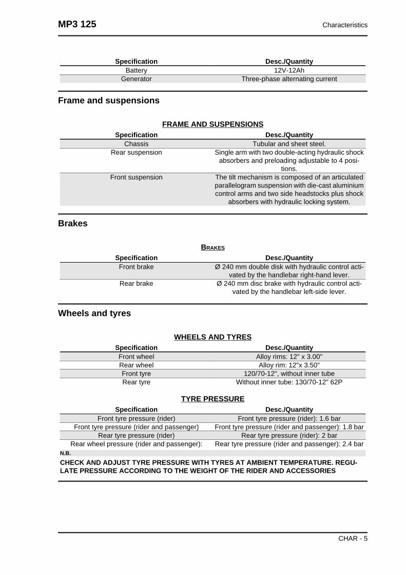
Frame and suspensions
FRAME AND SUSPENSIONSSpecification Desc./Quantity
Chassis Tubular and sheet steel.Rear suspension Single arm with two double-acting hydraulic shock
absorbers and preloading adjustable to 4 posi-tions.
Front suspension The tilt mechanism is composed of an articulatedparallelogram suspension with die-cast aluminiumcontrol arms and two side headstocks plus shock
absorbers with hydraulic locking system.
Brakes
BRAKES
Specification Desc./QuantityFront brake Ø 240 mm double disk with hydraulic control acti-
vated by the handlebar right-hand lever.Rear brake Ø 240 mm disc brake with hydraulic control acti-
vated by the handlebar left-side lever.
Wheels and tyres
WHEELS AND TYRESSpecification Desc./QuantityFront wheel Alloy rims: 12" x 3.00"Rear wheel Alloy rim: 12"x 3.50"Front tyre 120/70-12", without inner tubeRear tyre Without inner tube: 130/70-12" 62P
TYRE PRESSURESpecification Desc./Quantity
Front tyre pressure (rider) Front tyre pressure (rider): 1.6 barFront tyre pressure (rider and passenger) Front tyre pressure (rider and passenger): 1.8 bar
Rear tyre pressure (rider) Rear tyre pressure (rider): 2 barRear wheel pressure (rider and passenger): Rear tyre pressure (rider and passenger): 2.4 bar
N.B.
CHECK AND ADJUST TYRE PRESSURE WITH TYRES AT AMBIENT TEMPERATURE. REGU-LATE PRESSURE ACCORDING TO THE WEIGHT OF THE RIDER AND ACCESSORIES
MP3 125 Characteristics
CHAR - 5

Tightening Torques
STEERINGName Torque in Nm
Steering lower ring nut (central headstock) 22 ÷ 27 loosen by 90°Steering upper ring nut (central headstock) 27 ÷ 33
Handlebar fixing screw 50 ÷ 55Fixing screws for handlebar control assembly U-
bolts7 ÷ 10
FRAMEName Torque in Nm
Engine arm bolt - frame arm 33 ÷ 41Swinging arm buffer nut 64 - 72
Engine-swinging arm bolt 55 ÷ 61Frame-swinging arm bolt 55 ÷ 61
Centre stand bolt 31 ÷ 39
FRONT SUSPENSIONName Torque in Nm
Shock absorber lower clamp 19 ÷ 26Upper shock absorber clamp 19 ÷ 29
Front wheel fixing screws 19 ÷ 24Steering arm bolt nut 20 ÷ 25
Tilt calliper fixing screws 20 ÷ 25Front wheel shaft 74 ÷ 88
Arm coupling screws 45 ÷ 50Screws fixing arms to side headstocks 45 ÷ 50
Screws fixing arms to central headstock 45 ÷ 50Screws fixing the half-arm coupling flange 20 ÷ 25Fixing screws for tilt locking disc section 20 ÷ 25
Side headstock upper ring nut 20 - 24Side headstock lower ring nut 12 ÷ 15
Screw fixing sliding stem to shock absorber 45 ÷ 50Clamp for sliding stem locking device 6.5 ÷ 10.5
Fixing nuts for constant-velocity universal joints 18 ÷ 20Potentiometer to anti-tilting device clamp 8 ÷ 10Electric motor to anti-tilting device clamp 11 ÷ 13
Clamp fixing pump bolt to anti-tilting device 11 ÷ 13Pump to anti-tilting device clamp 11 ÷ 13
Pressure switch to distribution frame 18 ÷ 20Sensor to tilt gripper clamp 2.5 ÷ 2.9
Pipe terminals to fifth wheel check spring 7 ÷ 11Joint to anti-tilting device pump 20 ÷ 25
Lower fitting for shock absorber sliding lockingclamp pipes
20 ÷ 25
Upper fitting for shock absorber sliding lockingclamp pipes
20 ÷ 25
REAR SUSPENSIONName Torque in Nm
Upper shock absorber clamp 33 ÷ 41Shock absorber lower clamp 33 ÷ 41
Characteristics MP3 125
CHAR - 6
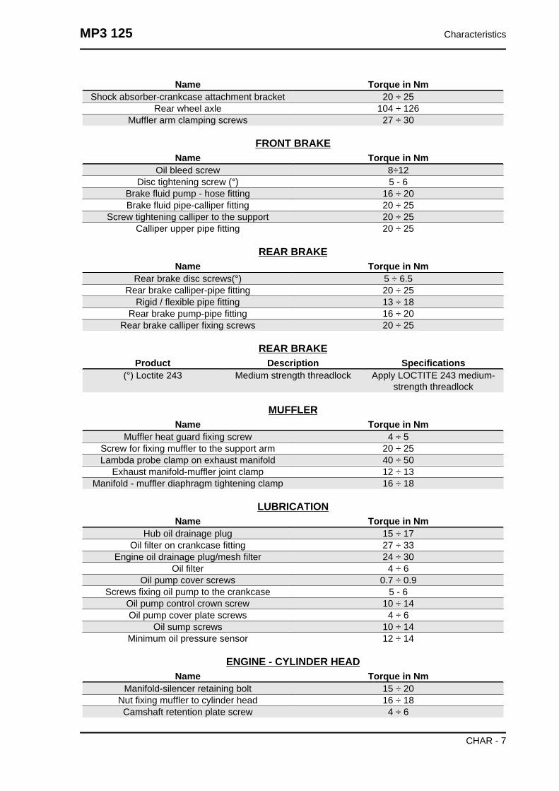
Name Torque in NmShock absorber-crankcase attachment bracket 20 ÷ 25
Rear wheel axle 104 ÷ 126Muffler arm clamping screws 27 ÷ 30
FRONT BRAKEName Torque in Nm
Oil bleed screw 8÷12Disc tightening screw (°) 5 - 6
Brake fluid pump - hose fitting 16 ÷ 20Brake fluid pipe-calliper fitting 20 ÷ 25
Screw tightening calliper to the support 20 ÷ 25Calliper upper pipe fitting 20 ÷ 25
REAR BRAKEName Torque in Nm
Rear brake disc screws(°) 5 ÷ 6.5Rear brake calliper-pipe fitting 20 ÷ 25
Rigid / flexible pipe fitting 13 ÷ 18Rear brake pump-pipe fitting 16 ÷ 20
Rear brake calliper fixing screws 20 ÷ 25
REAR BRAKEProduct Description Specifications
(°) Loctite 243 Medium strength threadlock Apply LOCTITE 243 medium-strength threadlock
MUFFLERName Torque in Nm
Muffler heat guard fixing screw 4 ÷ 5Screw for fixing muffler to the support arm 20 ÷ 25Lambda probe clamp on exhaust manifold 40 ÷ 50
Exhaust manifold-muffler joint clamp 12 ÷ 13Manifold - muffler diaphragm tightening clamp 16 ÷ 18
LUBRICATIONName Torque in Nm
Hub oil drainage plug 15 ÷ 17Oil filter on crankcase fitting 27 ÷ 33
Engine oil drainage plug/mesh filter 24 ÷ 30Oil filter 4 ÷ 6
Oil pump cover screws 0.7 ÷ 0.9Screws fixing oil pump to the crankcase 5 - 6
Oil pump control crown screw 10 ÷ 14Oil pump cover plate screws 4 ÷ 6
Oil sump screws 10 ÷ 14Minimum oil pressure sensor 12 ÷ 14
ENGINE - CYLINDER HEADName Torque in Nm
Manifold-silencer retaining bolt 15 ÷ 20Nut fixing muffler to cylinder head 16 ÷ 18Camshaft retention plate screw 4 ÷ 6
MP3 125 Characteristics
CHAR - 7

Name Torque in NmTiming chain tensioner central screw 5 - 6Timing chain tensioner support screw 11 ÷ 13
Starter ground support screw 11 ÷ 15Timing chain tensioner slider screw 10 ÷ 14
Inlet manifold screws 11 ÷ 13Tappet set screw lock nut 6 ÷ 8
Starter ground screw 7 ÷ 8.5Head fixing side screws 11 ÷ 12
Nuts fixing head to cylinder (*) 27 ÷ 29Tappet cover screws 6 ÷ 7
Spark plug 12 ÷ 14
ENGINE - TRANSMISSIONName Torque in Nm
Rear hub cover screws 24 ÷ 27Driven pulley shaft nut 54 ÷ 60
Transmission cover screws 11 ÷ 13Drive pulley nut 75 ÷ 83
Clutch unit nut on driven pulley 55 ÷ 60Belt support roller screw 11 ÷ 13
ENGINE - FLYWHEELName Torque in Nm
Pick-Up clamping screws 3 ÷ 4Stator assembly screws (°) 3 ÷ 4
Flywheel cover fixing screws 5 - 6Flywheel nut (250) 94 ÷ 102
Screw fixing freewheel to flywheel 13 ÷ 15
CRANKCASE AND CRANKSHAFTName Torque in Nm
Internal engine crankcase bulkhead (transmis-sion-side half shaft) screws
4 ÷ 6
Engine-crankcase coupling screws 11 ÷ 13Starter motor screws 11 ÷ 13
Crankcase timing system cover screws (°) 3.5 ÷ 4.5
ENGINE - COOLINGProduct Description Specifications
(°) Loctite 243 Medium strength threadlock Apply LOCTITE 243 medium-strength threadlock
Overhaul data
Assembly clearances
Characteristics MP3 125
CHAR - 8

Cylinder - piston assy.
ENGINE COUPLING CATEGORIESName Initials Cylinder Piston Play on fitting
Cylinder A 56.997 ÷ 57.004 56.945 ÷ 56.952 0.045 - 0.059Cylinder B 57.004 ÷ 57.011 56.952 ÷ 56.959 0.045 - 0.059Piston C 57.011 ÷ 57.018 56.959 ÷ 56.966 0.045 - 0.059Piston D 57.018 ÷ 57.025 56.966 ÷ 56.973 0.045 - 0.059
Cylinder 1st Over-size
A1 57.197 ÷ 57.204 57.145 ÷ 57.152 0.045 - 0.059
Cylinder 1st Over-size
B 1 57.204 ÷ 57.211 57.152 ÷ 57.159 0.045 - 0.059
Piston 1st Over-size
C 1 57.211 ÷ 57.218 57.159 ÷ 57.166 0.045 - 0.059
Piston 1st Over-size
D 1 57.218 ÷ 57.225 57.166 ÷ 57.173 0.045 - 0.059
Cylinder 2nd Over-size
A2 57.397 ÷ 57.404 57.345 ÷ 57.352 0.045 - 0.059
Cylinder 2nd Over-size
B 2 57.404 ÷ 57.411 57.352 ÷ 57.359 0.045 - 0.059
Piston 2nd Over-size
C 2 57.411 ÷ 57.418 57.359 ÷ 57.366 0.045 - 0.059
Piston 2nd Over-size
D 2 57.418 ÷ 57.425 57.366 ÷ 57.373 0.045 - 0.059
Cylinder 3rd Over-size
A 3 57.597 ÷ 57.604 57.545 ÷ 57.552 0.045 - 0.059
Cylinder 3rd Over-size
B 3 57.604 ÷ 57.611 57.552 ÷ 57.559 0.045 - 0.059
Piston 3rd Over-size
C 3 57.611 ÷ 57.618 57.559 ÷ 57.566 0.045 - 0.059
Piston 3rd Over-size
D 3 57.618 ÷ 57.625 57.566 ÷ 57.573 0.045 - 0.059
MP3 125 Characteristics
CHAR - 9
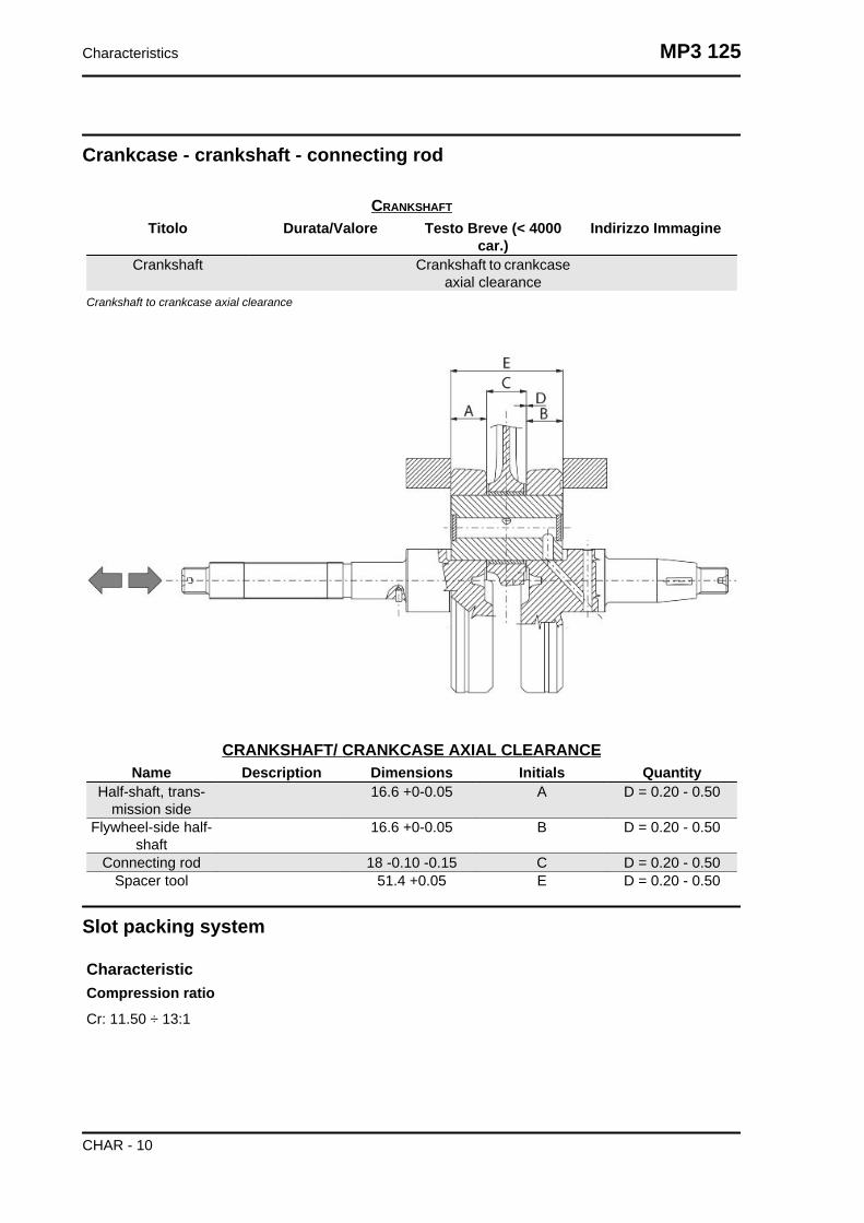
Crankcase - crankshaft - connecting rod
CRANKSHAFT
Titolo Durata/Valore Testo Breve (< 4000car.)
Indirizzo Immagine
Crankshaft Crankshaft to crankcaseaxial clearance
Crankshaft to crankcase axial clearance
CRANKSHAFT/ CRANKCASE AXIAL CLEARANCEName Description Dimensions Initials Quantity
Half-shaft, trans-mission side
16.6 +0-0.05 A D = 0.20 - 0.50
Flywheel-side half-shaft
16.6 +0-0.05 B D = 0.20 - 0.50
Connecting rod 18 -0.10 -0.15 C D = 0.20 - 0.50Spacer tool 51.4 +0.05 E D = 0.20 - 0.50
Slot packing system
CharacteristicCompression ratio
Cr: 11.50 ÷ 13:1
Characteristics MP3 125
CHAR - 10

Measurement «A» to be taken, is a value of piston protrusion. It indicates by how much the plane formed
by the piston crown protrudes from the plane formed by the upper part of the cylinder. The further the
piston protrudes from the cylinder, the thicker the base gasket to be used (to restore the compression
ratio) and vice versa.N.B.
NO GASKETS AND SEALS SHOULD BE ASSEMBLED BETWEEN THE CRANKCASE AND CYL-INDER AND THE DIAL GAUGE EQUIPPED WITH SUPPORT SHOULD BE SET TO ZERO FORMEASUREMENT «A» TO BE TAKEN WITH THE PISTON AT TOP DEAD CENTRE POSITION ANDON A RECTIFIED PLANE.
MODELS WITH FIBRE HEAD GASKET (1.1)Name Measure A Thickness
Shimming 125 - Cylinder 67 -Head gasket 1.1 - Base gasket
0.4
2.20 ÷ 2.45 0.4 ± 0.05
Shimming 125 - Cylinder 67 -Head gasket 1.1 - Base gasket
0.6
2.45 ÷ 2.70 0.6 ± 0.05
CharacteristicCompression ratio
Cr: 11.50 ÷ 13:1
MP3 125 Characteristics
CHAR - 11

Measurement «A» to be taken, is a value of piston protrusion. It indicates by how much the plane formed
by the piston crown protrudes from the plane formed by the upper part of the cylinder. The further the
piston protrudes from the cylinder, the thicker the base gasket to be used (to restore the compression
ratio) and vice versa.N.B.
NO GASKETS AND SEALS SHOULD BE ASSEMBLED BETWEEN THE CRANKCASE AND CYL-INDER AND THE DIAL GAUGE EQUIPPED WITH SUPPORT SHOULD BE SET TO ZERO FORMEASUREMENT «A» TO BE TAKEN WITH THE PISTON AT TOP DEAD CENTRE POSITION ANDON A RECTIFIED PLANE.
MODELS WITH METALLIC HEAD GASKET (0.3)Name Measure A Thickness
Shimming 125 - Cylinder 67.8 -Head gasket 0.3 - Base gasket
0.4
1.40 ÷ 1.65 0.4 ± 0.05
Shimming 125 - Cylinder 67.8 -Head gasket 0.3 - Base gasket
0.6
1.65 ÷ 1.90 0.6 ± 0.05
Products
RECOMMENDED PRODUCTS TABLEProduct Description Specifications
AGIP ROTRA 80W-90 Rear hub oil SAE 80W/90 Oil that exceeds therequirements of API GL3 specifi-
cations
Characteristics MP3 125
CHAR - 12

Product Description SpecificationsAGIP CITY HI TEC 4T Oil to lubricate flexible transmis-
sions (throttle control)Oil for 4-stroke engines
AGIP FILTER OIL Oil for air filter sponge Mineral oil with specific additivesfor increased adhesiveness
AGIP GP 330 Calcium complex soap-basedgrease with NLGI 2; ISO-L-
XBCIB2
Grease (brake control levers,throttle grip)
AGIP CITY HI TEC 4T Engine oil SAE 5W-40, API SL, ACEA A3,JASO MA Synthetic oil
AGIP BRAKE 4 Brake fluid FMVSS DOT 4 Synthetic fluidSPECIAL AGIP PERMANENT
fluidcoolant Monoethylene glycol-based anti-
freeze fluid, CUNA NC 956-16
MP3 125 Characteristics
CHAR - 13

Characteristics MP3 125
CHAR - 14

INDEX OF TOPICS
TOOLING TOOL

APPROPRIATE TOOLStores code Description
001330Y Tool for fitting steering seats
001467Y014 Pliers to extract ø 15-mm bear-ings
005095Y Engine support
002465Y Pliers for circlips
006029Y Punch for fitting fifth wheel seaton steering tube
020004Y Punch for removing fifth wheelsfrom headstock
020055Y Wrench for steering tube ring nut
Tooling MP3 125
TOOL - 2

Stores code Description020074Y Support base for checking crank-
shaft alignment
020150Y Air heater support
020151Y Air heater
020193Y Oil pressure gauge
020262Y Crankcase splitting strip
020263Y Sheath for driven pulley fitting
MP3 125 Tooling
TOOL - 3

Stores code Description020306Y Punch for assembling valve seal
rings
020329Y MityVac vacuum-operated pump
020330Y Stroboscopic light for timing con-trol
020331Y Digital multimeter
020332Y Digital rev counter
Tooling MP3 125
TOOL - 4

Stores code Description020333Y Single battery charger
020334Y Multiple battery charger
020335Y Magnetic support for dial gauge
020357Y 32 x 35 mm adaptor020359Y 42x47-mm adaptor
020360Y Adaptor 52 x 55 mm
MP3 125 Tooling
TOOL - 5

Stores code Description020363Y 20 mm guide
020375Y Adaptor 28 x 30 mm
020376Y Adaptor handle
020382Y Valve cotters equipped with part012 removal tool
020382Y011 adapter for valve removal tool
Tooling MP3 125
TOOL - 6

Stores code Description020393Y Piston fitting band
020412Y 15 mm guide
020423Y driven pulley lock wrench
020424Y Driven pulley roller casing fittingpunch
020426Y Piston fitting fork
MP3 125 Tooling
TOOL - 7

Stores code Description020431Y Valve oil seal extractor
020434Y Oil pressure control fitting
020444Y Tool for fitting/ removing the driv-en pulley clutch
020456Y Ø 24 mm adaptor020477Y Adaptor 37 mm
020483Y 30 mm guide
Tooling MP3 125
TOOL - 8
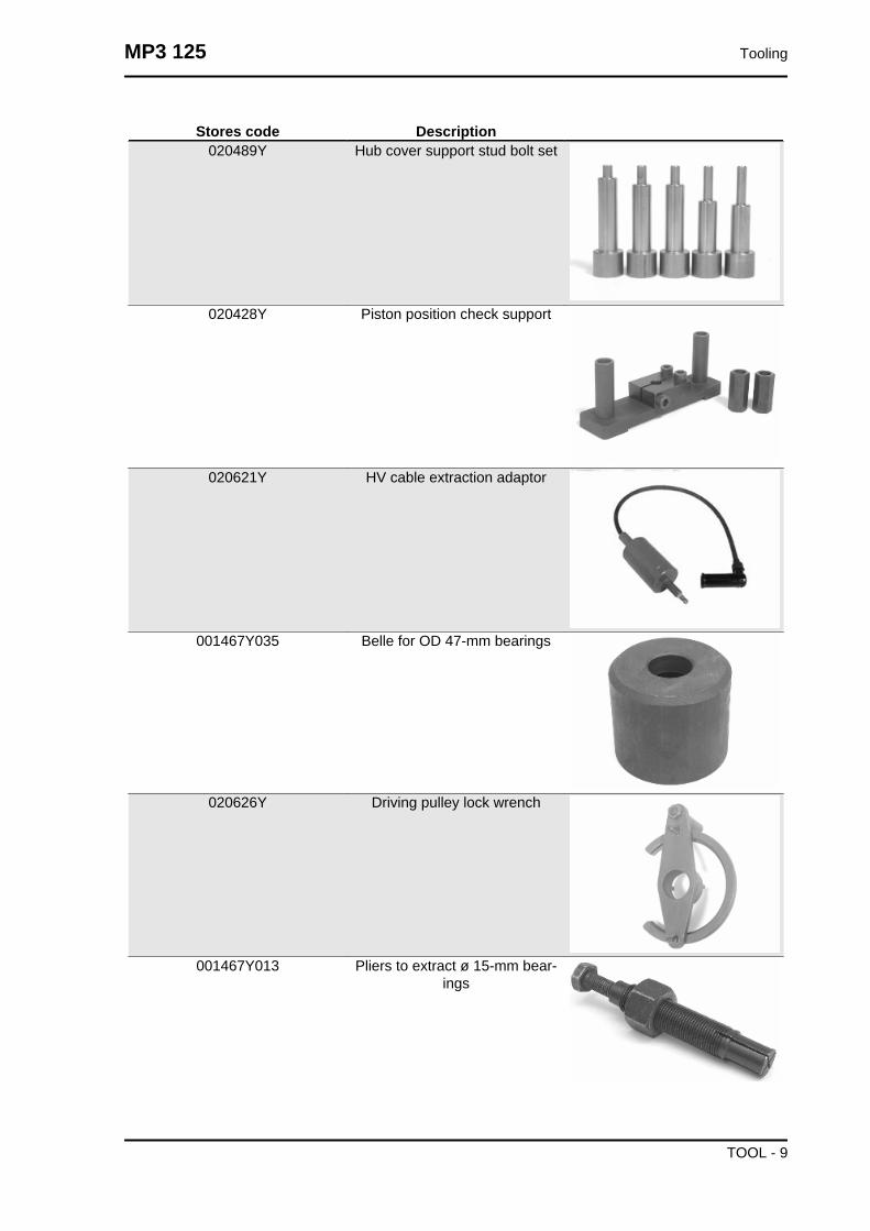
Stores code Description020489Y Hub cover support stud bolt set
020428Y Piston position check support
020621Y HV cable extraction adaptor
001467Y035 Belle for OD 47-mm bearings
020626Y Driving pulley lock wrench
001467Y013 Pliers to extract ø 15-mm bear-ings
MP3 125 Tooling
TOOL - 9

Stores code Description020627Y Flywheel lock wrench
020467Y Flywheel extractor
020454Y Tool for fitting piston pin stops(200 - 250)
020622Y Transmission-side oil guardpunch
020480Y Petrol pressure check set
020244Y 15 mm diameter punch
Tooling MP3 125
TOOL - 10

Stores code Description020115Y Ø 18 punch
020271Y Tool for removing-fitting silentbloc
001467Y017 Driver for OD 36 mm bearings
020234y extractor020441Y 26 x 28 mm adaptor
020362Y 12 mm guide
020358Y 37x40-mm adaptor
MP3 125 Tooling
TOOL - 11

Stores code Description001467Y002 Driver for OD 73 mm bearing
020641Y EFI Technology software up-grade
020469Y Reprogramming kit for scooterdiagnosis tester
020639Y Tilt locking control unit software
020481Y Control unit interface wiring
Tooling MP3 125
TOOL - 12

Stores code Description020481Y004 Parking control unit interface wir-
ing
020460Y Scooter diagnosis and tester
MP3 125 Tooling
TOOL - 13

Tooling MP3 125
TOOL - 14

INDEX OF TOPICS
MAINTENANCE MAIN

Follow these steps to reset the service icons:
1. With the key set to OFF, hold down the
"SET" button and turn the key to ON : the
"BELT" and "SERVICE" icons start flashing.
2. Push the "CLOCK" button for less than 1
second and the icons are displayed sequen-
tially. The icon selected remains ON and the
other is no longer displayed.
3. Press the "CLOCK" button again for more
than 3 seconds to reset the relative mainte-
nance step and the icon is no longer dis-
played.
Maintenance chart
EVERY 2 YEARS75
ActionCoolant - changeBrake fluid - changesecondary air filter - cleaning
EVERY 3.000 KM10'
ActionEngine oil - level check/ top-up
AFTER 1,000 KM
90'Action
Engine oil - replacementHub oil - changeEngine oil - changeIdle speed (*) - adjustmentThrottle lever - adjustmentSteering - adjustmentBrake control levers - greasingBrake pads - check condition and wearBrake fluid level - checkTilt locking gripper control cable - adjustmentSafety locks - checkElectrical system and battery - checkTyre pressure and wear - checkVehicle and brake test - road test
(*) See instructions in «Idle speed adjustment» section
Maintenance MP3 125
MAIN - 2

AFTER 6.000 KM
130'Action
Hub oil level - checkSpark plug/ electrode gap - checkAir filter - cleanSliding blocks / variable speed rollers - checkDriving belt - checkCoolant level - checkBrake pads - check condition and wearBrake fluid level - checkTilt locking gripper control cable - adjustmentElectrical system and battery - checkTyre pressure and wear - checkVehicle and brake test - road testEngine oil - changeOil filter -ReplacementValve clearance - check
AFTER 12,000 KM AND AFTER 60,000 KM
140'Action
Engine oil - replacementHub oil level - checkSpark plug / electrode gap - check / replacementAir filter - cleanEngine oil - changeIdle speed (*) - adjustmentSliding block / variable speed rollers - changeThrottle lever - adjustmentCoolant level - checkSteering - adjustmentBrake control levers - greasingBrake pads - check condition and wearBrake fluid level - checkTilt locking gripper control cable - adjustmentTransmission elements - lubricationSafety locks - checkSuspensions - checkElectrical system and battery - checkHeadlight - adjustmentTyre pressure and wear - checkVehicle and brake test - road testDriving Belt - replacement
(*) See instructions in «Idle speed adjustment» section
AFTER 18,000 KM AND AFTER 54,000 KM
110'Action
Hub oil level - checkSpark plug/ electrode gap - checkAir filter - clean
MP3 125 Maintenance
MAIN - 3

ActionSliding blocks / variable speed rollers - checkDriving belt - checkCoolant level - checkRadiator - external cleaning/ checkBrake pads - check condition and wearBrake fluid level - checkTilt locking gripper control cable - adjustmentElectrical system and battery - checkTyre pressure and wear - checkVehicle and brake test - road testEngine oil - changeOil filter -ReplacementValve clearance - Check
AFTER 24,000 KM AND AFTER 48,000 KM
170'Action
Engine oil - replacementHub oil - changeSpark plug / electrode gap - check / replacementAir filter - cleanEngine oil - changeIdle speed (*) - adjustmentSliding block / variable speed rollers - changeThrottle lever - adjustmentCoolant level - checkSteering - adjustmentBrake control levers - greasingBrake pads - check condition and wearBrake fluid level - checkTilt locking gripper control cable - adjustmentTransmission elements - lubricationSafety locks - checkSuspensions - checkElectrical system and battery - checkHeadlight - adjustmentTyre pressure and wear - checkVehicle and brake test - road testDriving Belt - replacement
(*) See instructions in «Idle speed adjustment» section
AFTER 30,000 KM, AFTER 42,000 KM AND AFTER 66,000 KM
100'Action
Hub oil level - checkSpark plug/ electrode gap - checkAir filter - cleanSliding blocks / variable speed rollers - checkDriving belt - checkCoolant level - checkBrake pads - check condition and wearBrake fluid level - checkTilt locking gripper control cable - adjustment
Maintenance MP3 125
MAIN - 4

ActionElectrical system and battery - checkTyre pressure and wear - checkVehicle and brake test - road testEngine oil - changeOil filter -Replacement
AFTER 36.000 KM
260'Action
Engine oil - replacementHub oil level - checkSpark plug / electrode gap - check / replacementAir filter - cleanEngine oil - changeValve clearance - CheckIdle speed (*) - adjustmentSliding block / variable speed rollers - changeThrottle lever - adjustmentDriving belt - replacementCoolant level - checkRadiator - external cleaning/ checkSteering - adjustmentBrake control levers - greasingBrake pads - check condition and wearBrake fluid hoses - replacementBrake fluid level - checkTilt locking gripper control cable - adjustmentTransmission elements - lubricationSafety locks - checkSuspensions - checkElectrical system and battery - checkHeadlight - adjustmentTyre pressure and wear - checkVehicle and brake test - road test
(*) See instructions in «Idle speed adjustment» section
AFTER 72.000 KM
280'Action
Engine oil - replacementHub oil - changeSpark plug / electrode gap - check / replacementAir filter - cleanEngine oil - changeValve clearance - CheckIdle speed (*) - adjustmentSliding block / variable speed rollers - changeThrottle lever - adjustmentDriving belt - replacementCoolant level - checkRadiator - external cleaning/ checkSteering - adjustmentBrake control levers - greasing
MP3 125 Maintenance
MAIN - 5

ActionBrake pads - check condition and wearBrake fluid hoses - replacementBrake fluid level - checkTilt locking gripper control cable - adjustmentTransmission elements - lubricationSafety locks - checkSuspensions - checkElectrical system and battery - checkHeadlight - adjustmentTyre pressure and wear - checkVehicle and brake test - road test
(*) See instructions in «Idle speed adjustment» section
Carburettor
- Disassemble the carburettor in its parts, wash all of them with solvent, dry all body grooves with
compressed air to ensure adequate cleaning.
- Check carefully that the parts are in good condition.
- The throttle valve should move freely in the chamber. Replace it in case of excessive clearance due
to wear.
- If there are wear marks in the chamber causing inadequate tightness or a free valve slide (even if it
is new), replace the carburettor.
- It is advisable to replace the gaskets at every refitWARNING
PETROL IS HIGHLY EXPLOSIVE ALWAYS REPLACE THE GASKETS TO AVOID PETROL LEAKS
Checking the spark advance
The ignition advance is determined electronically
on the basis of parameters known by the control
unit. For this reason it is not possible to declare the
reference values based on the engine rpm. The
ignition timing value is detectable any time using
the diagnostic tester. It is possible to check wheth-
er the ignition advance determined by the system
does in fact correspond with the value actually ac-
tivated on the engine, by means of the strobo-
scopic light.
Proceed as follows:
- Remove the spark plug.
- Remove the transmission crankcase.
Maintenance MP3 125
MAIN - 6

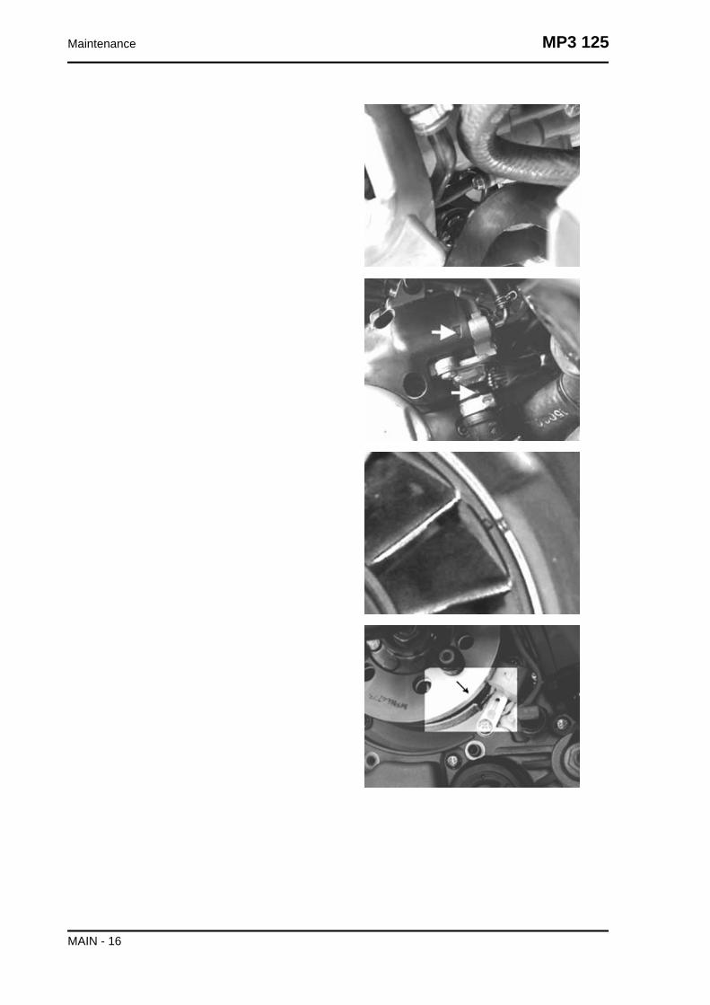
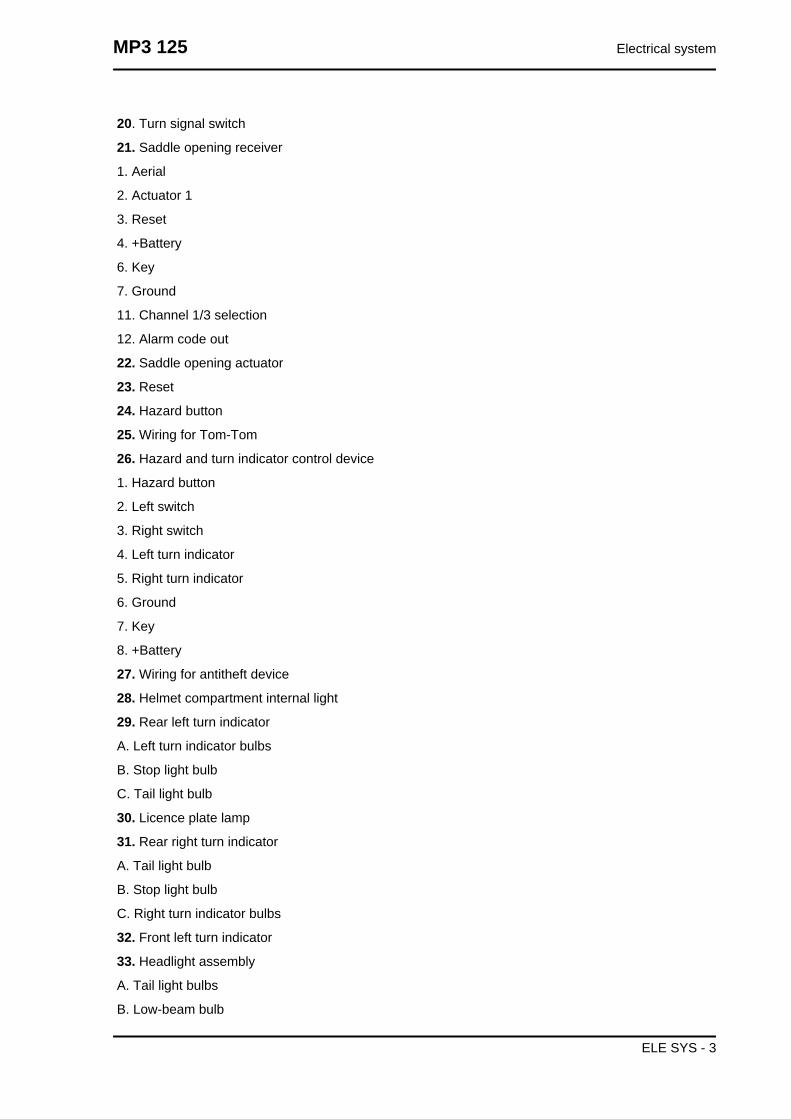
- Rotate the driving pulley fan until the reference
marks between the flywheel and flywheel cover
coincide as shown in the photograph.
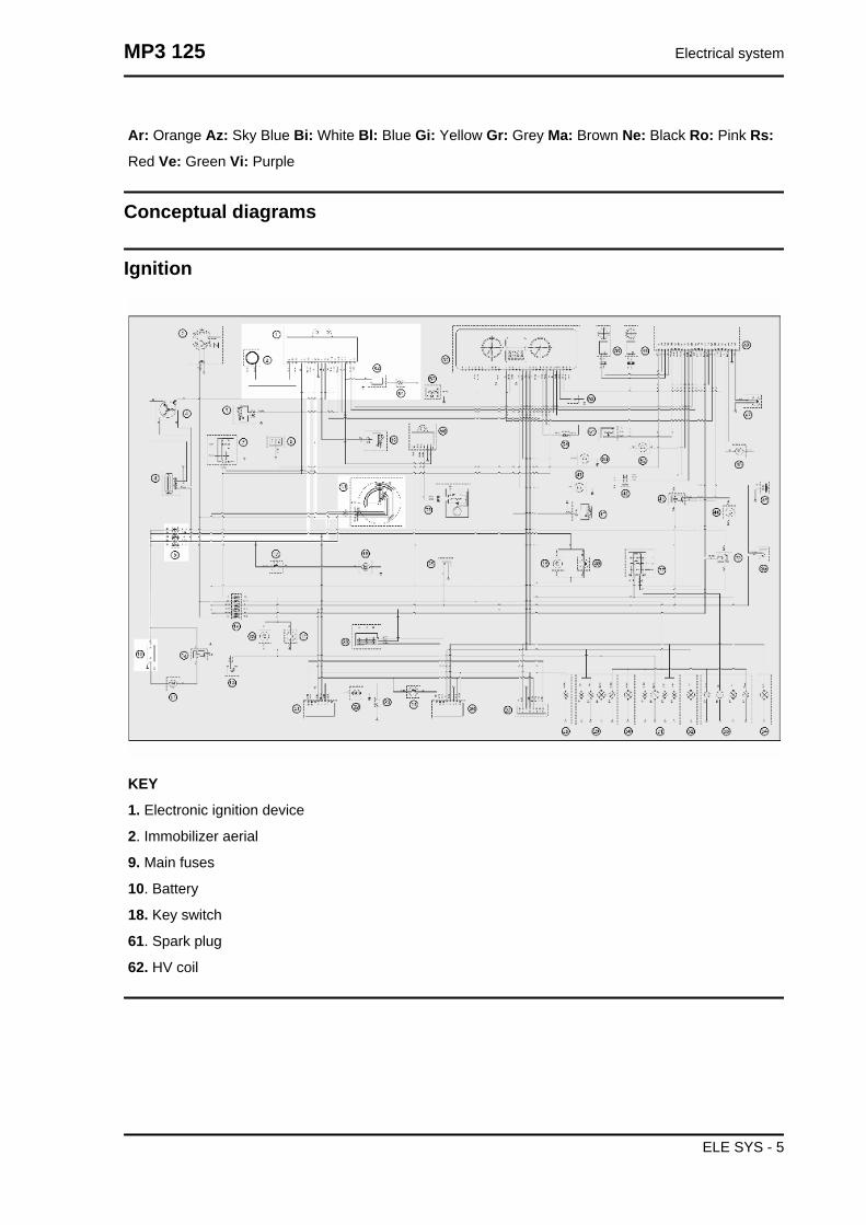
- Bring the reference mark onto the transmission
side between the fan and the transmission cover
as shown in the photograph.
- Refit the spark plug.
- Refit the plastic cap on the flywheel cover.
- Adjust the spark gap to the contact position (no
reference mark visible) and install it on engine be-
tween the spark plug and spark plug cap
- Connect the induction calliper on the spark gap
cable respecting the proper polarity (the arrow on
the calliper must be pointing at the spark plug).
- Connect the diagnostic tester.
- Start the engine.
- Select the «parameter» function in this menu.
- Select the stroboscopic light command in the tra-
ditional four-stroke engine position (1 spark 2
revs).
- Check that the real values of rpm and ignition
advance match those measured using the diag-
nostic tester.
If the values do not correspond, check:
- distribution timing
- revolution-timing sensor
- Injection control unit
Specific tooling020460Y Scooter diagnosis and tester
020330Y Stroboscopic light for timing control
020621Y HV cable extraction adaptor
MP3 125 Maintenance
MAIN - 7
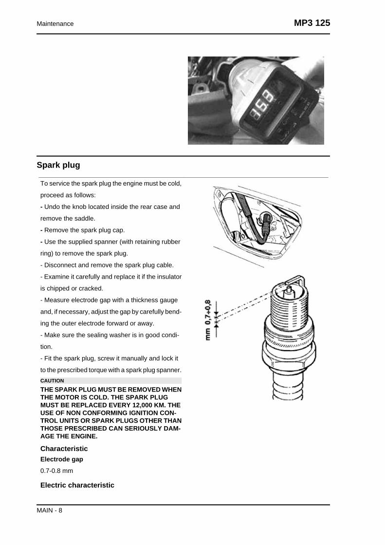
Spark plug
To service the spark plug the engine must be cold,
proceed as follows:
- Undo the knob located inside the rear case and
remove the saddle.
- Remove the spark plug cap.
- Use the supplied spanner (with retaining rubber
ring) to remove the spark plug.
- Disconnect and remove the spark plug cable.
- Examine it carefully and replace it if the insulator
is chipped or cracked.
- Measure electrode gap with a thickness gauge
and, if necessary, adjust the gap by carefully bend-
ing the outer electrode forward or away.
- Make sure the sealing washer is in good condi-
tion.
- Fit the spark plug, screw it manually and lock it
to the prescribed torque with a spark plug spanner.CAUTION
THE SPARK PLUG MUST BE REMOVED WHENTHE MOTOR IS COLD. THE SPARK PLUGMUST BE REPLACED EVERY 12,000 KM. THEUSE OF NON CONFORMING IGNITION CON-TROL UNITS OR SPARK PLUGS OTHER THANTHOSE PRESCRIBED CAN SERIOUSLY DAM-AGE THE ENGINE.
CharacteristicElectrode gap
0.7-0.8 mm
Electric characteristic
Maintenance MP3 125
MAIN - 8

Spark plug
NGK CR 8EB
Locking torques (N*m)Spark plug 12 ÷ 14
Hub oil
Make sure that there is oil in the rear hub (amount
of oil contained ~ 150 cm³). To check the rear hub
oil level, proceed as follows:
1) Park the scooter on level ground and place it on
the centre stand.
2) Unscrew the dipstick "A", dry it with a clean rag
and then reinsert it, screwing it tightly into
place;
3) Remove the dipstick and check that the oil level
is above the first notch from the bottom.
4) Screw the dipstick back in, checking that it is
locked in place.N.B.
THE REFERENCE MARKS ON THE HUB OILLEVEL DIPSTICK, EXCEPT FOR THE ONE IN-DICATING THE "MAX" LEVEL, REFER TO OTH-ER MODELS BY THE MANUFACTURER ANDHAVE NO SPECIFIC FUNCTION FOR THISMODEL.CAUTION
RIDING THE VEHICLE WITH INSUFFICIENTHUB LUBRICATION OR WITH CONTAMINA-TED OR IMPROPER LUBRICANTS ACCELER-ATES THE WEAR AND TEAR OF THE MOVINGPARTS AND CAN CAUSE SERIOUS DAMAGE.CAUTION
USED OILS CONTAIN SUBSTANCES HARM-FUL TO THE ENVIRONMENT. FOR OIL RE-PLACEMENT, CONTACT AN AUTHORISEDSERVICE CENTRE, WHICH IS EQUIPPED TODISPOSE OF USED OILS IN AN ENVIRONMEN-TALLY FRIENDLY AND LEGAL WAY.CAUTION
MP3 125 Maintenance
MAIN - 9

UPON REPLACING HUB OIL, AVOID THE OILCOMING INTO CONTACT WITH THE REARBRAKE DISC.
Recommended productsAGIP ROTRA 80W-90 Rear hub oil
SAE 80W/90 Oil that exceeds the requirements of
API GL3 specifications
Check
- Rest the vehicle on its centre stand on an even surface. - Unscrew the oil dipstick, dry it with a clean
cloth and reinsert it, screwing it in thoroughly.- Take out the dipstick and check that the oil level reaches
the 2nd notch from the bottom.- Screw the dipstick back into place completely.
Recommended productsAGIP ROTRA 80W-90 Rear hub oil
SAE 80W/90 Oil that exceeds the requirements of API GL3 specifications
Locking torques (N*m)Hub oil drainage plug 15 ÷ 17
Replacement
-Remove the oil cap «A».
- Unscrew the oil drainage cap "B" and drain out
all the oil.
- Screw on the drainage plug and fill up the hub
with oil (about 150 cc)
Air filter
Remove the air cleaner cap after undoing the re-
tainer screws, then extract the filter.
- Wash with water and neutral soap.
-Dry with a clean cloth and short blasts of com-
pressed air.
- Soak with a mixture of 50% petrol and 50% SE-
LENIA AIR FILTER OIL.
Maintenance MP3 125
MAIN - 10

-Drip dry the filter and then squeeze it between the
hands without wringing.CAUTION
NEVER RUN THE ENGINE WITHOUT THE AIRFILTER, THIS WOULD RESULT IN AN EXCES-SIVE WEAR OF THE PISTON AND CYLINDER.CAUTION
WHEN TRAVELLING ON DUSTY ROADS, THEAIR FILTER MUST BE CLEANED MORE OFTENTHAN SHOWN IN THE SCHEDULED MAINTE-NANCE CHART.
Engine oil
Replacement
The engine oil and cartridge filter, "C", must be re-
placed after the first km, and every 6.000 km there-
after, by an Authorised Piaggio Service Cen-
tre. The engine should be emptied by draining the
oil from the drainage cap "B" of the gauze filter on
the flywheel side. In order to facilitate the oil drain-
age, loosen the cap/dipstick. Since a certain quan-
tity of oil remains in the circuit still, the top-up
should be carried out with around 600 ÷ 650 cm³
of oil from cap "A". Then start up the scooter, leave
it running for a few minutes and switch it off: after
five minutes, check the level and if necessary top
up without exceeding the MAX. level. The car-
tridge filter must be replaced at every oil change.
For top up and change, use new oil of the recom-
mended type.WARNING
RUNNING THE ENGINE WITH INSUFFICIENTLUBRICATION OR WITH INADEQUATE LUBRI-CANTS ACCELERATES THE WEAR AND TEAROF THE MOVING PARTS AND CAN CAUSE IR-RETRIEVABLE DAMAGE.WARNING
MP3 125 Maintenance
MAIN - 11

EXCESSIVE OIL LEVEL AT TOP-UPS CANLEAD TO SCALE FORMATION AND VEHICLEMALFUNCTIONING.CAUTION
USED OILS CONTAIN SUBSTANCES HARM-FUL TO THE ENVIRONMENT. FOR OIL RE-PLACEMENT, CONTACT AN AUTHORISEDPIAGGIO SERVICE CENTRE, AS THEY AREEQUIPPED TO DISPOSE OF SPENT OILS IN ANENVIRONMENTALLY FRIENDLY AND LEGALWAY.CAUTION
USING OILS OTHER THAN THOSE RECOM-MENDED CAN SHORTEN THE LIFE OF THEENGINE.
Recommended productsAGIP CITY HI TEC 4T Engine oil
SAE 5W-40, API SL, ACEA A3, JASO MA Syn-
thetic oil
Check
Every time the scooter is used, a visual check
should be made on the level of the engine oil when
the engine is cold. The oil level should be some-
where between the MAX and MIN index marks on
the level bar; the check must be made with the
scooter upright, resting on the centre stand. If the
check is carried out after the vehicle has been
used, and therefore with a hot engine, the level line
will be lower; in order to carry out a correct check
it is necessary to wait at least 10 minutes after the
engine has been stopped, so as to get the correct
level.
Maintenance MP3 125
MAIN - 12

Checking the ignition timing
-Remove the 4 fixing screws and move away from
the engine the flywheel cover fitted with a water
pump and cooling manifolds.
-Rotate the flywheel until the reference matches
the crankcase operation end as shown in the figure
(TDC). Make sure that the 4V reference point on
the camshaft control pulley is aligned with the ref-
erence point on the head as shown in the second
figure. If the reference mark is opposite the indi-
cator on the head, make the crankshaft turn once
more.
-The TDC reference mark is repeated also be-
tween the flywheel cooling fan and the flywheel
cover.
To use this reference mark, remove the spark plug
and turn the engine in the opposite direction to the
normal direction using a calliper spanner applied
to the camshaft command pulley casing.N.B.
TIME THE TIMING SYSTEM UNIT IF IT IS NOTIN PHASE.
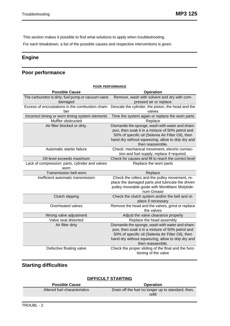
Checking the valve clearance
-To check valve clearance, centre the reference
marks of the timing system
- Use a thickness gauge to check that the clear-
ance between the valve and the register corre-
sponds with the indicated values. When the valve
clearance values, intake and drainage respective-
ly, are different from the ones indicated below,
adjust them by loosening the lock nut and operate
on the register with a screwdriver as shown in the
figure.
Intake: 0.10 mm (when cold)
Discharge: 0.15 mm (when cold)
MP3 125 Maintenance
MAIN - 13

Headlight adjustment
Proceed as follows:
1. Position the unloaded vehicle, in running order
and with the tyres inflated to the prescribed pres-
sure, on a flat surface 10 m away from a half-lit
white screen; ensure that the longitudinal axis of
the vehicle is perpendicular to the screen;
2. Remove the headlight assembly central cover
3. Turn on the headlight and check that the limit of
the projected light beam is not over 9/10 or below
7/10 of the distance from the ground to the centre
of the vehicle headlight;
4. Otherwise, adjust the headlight with the
screws«A» indicated in the figureN.B.
THE ABOVE PROCEDURE COMPLIES WITHTHE EUROPEAN STANDARDS REGARDINGMAXIMUM AND MINIMUM HEIGHT OF LIGHTBEAMS. REFER TO THE STATUTORY REGU-LATIONS IN FORCE IN EVERY COUNTRYWHERE THE vehicle IS USED.
SAS filters inspection and cleaning
Insert the filter into its housing.
Fit the valve support with the 3 screws
Insert the rubber spacer on the valve and proceed
with the assembly on the support.
Fix the support with the 2 screws.
Fit the pre-filter and position it matching the 2 ref-
erences shown in the figure.
Fit the sealing gasket.
Maintenance MP3 125
MAIN - 14
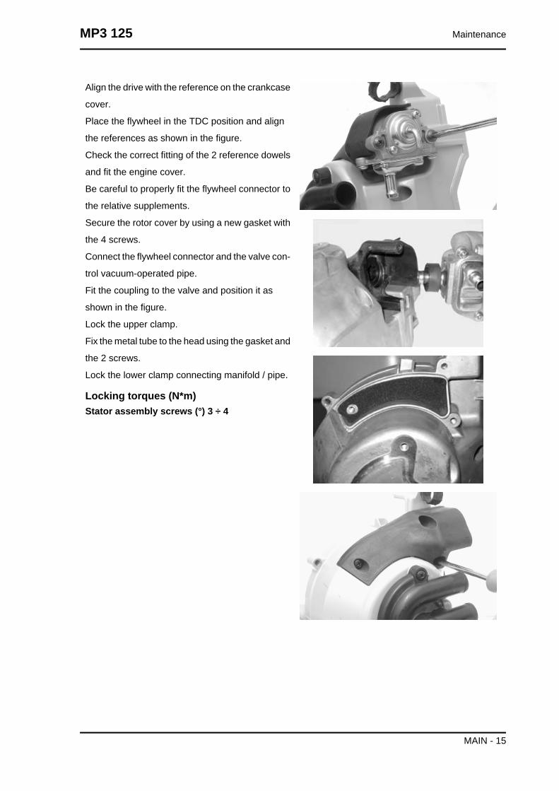
Align the drive with the reference on the crankcase
cover.
Place the flywheel in the TDC position and align
the references as shown in the figure.
Check the correct fitting of the 2 reference dowels
and fit the engine cover.
Be careful to properly fit the flywheel connector to
the relative supplements.
Secure the rotor cover by using a new gasket with
the 4 screws.
Connect the flywheel connector and the valve con-
trol vacuum-operated pipe.
Fit the coupling to the valve and position it as
shown in the figure.
Lock the upper clamp.
Fix the metal tube to the head using the gasket and
the 2 screws.
Lock the lower clamp connecting manifold / pipe.
Locking torques (N*m)Stator assembly screws (°) 3 ÷ 4
MP3 125 Maintenance
MAIN - 15
Maintenance MP3 125
MAIN - 16

Undo the 3 fixing screws "A", remove the secon-
dary air filter cover and then take out the filtering
element "B".
- Wash with water and neutral soap.
-Dry with a clean cloth and short blasts of com-
pressed air.
Remove the flywheel cover by operating on its
clamps and remove the primary filtering element.
- Wash with water and neutral soap.
-Dry with a clean cloth and short blasts of com-
pressed air.
Check that the filter casing is clean paying special
attention to "A" and "B" passagesCAUTION
NEVER RUN THE ENGINE WITHOUT THE SEC-ONDARY AIR FILTERCAUTION
WHEN TRAVELLING ON DUSTY ROADS, THEAIR FILTER MUST BE CLEANED MORE OFTENTHAN SHOWN IN THE SCHEDULED MAINTE-NANCE CHART.
MP3 125 Maintenance
MAIN - 17

Maintenance MP3 125
MAIN - 18

INDEX OF TOPICS
TROUBLESHOOTING TROUBL
This section makes it possible to find what solutions to apply when troubleshooting.
For each breakdown, a list of the possible causes and respective interventions is given.
Engine
Poor performance
POOR PERFORMANCE
Possible Cause OperationThe carburettor is dirty; fuel pump or vacuum valve
damagedRemove, wash with solvent and dry with com-
pressed air or replaceExcess of encrustations in the combustion cham-
berDescale the cylinder, the piston, the head and the
valvesIncorrect timing or worn timing system elements Time the system again or replace the worn parts
Muffler obstructed ReplaceAir filter blocked or dirty. Dismantle the sponge, wash with water and sham-
poo, then soak it in a mixture of 50% petrol and50% of specific oil (Selenia Air Filter Oil), then
hand dry without squeezing, allow to drip dry andthen reassemble.
Automatic starter failure Check: mechanical movement, electric connec-tion and fuel supply, replace if required.
Oil level exceeds maximum Check for causes and fill to reach the correct levelLack of compression: parts, cylinder and valves
wornReplace the worn parts
Transmission belt worn ReplaceInefficient automatic transmission Check the rollers and the pulley movement, re-
place the damaged parts and lubricate the drivenpulley moveable guide with Montblanc Molybde-
num GreaseClutch slipping Check the clutch system and/or the bell and re-
place if necessaryOverheated valves Remove the head and the valves, grind or replace
the valvesWrong valve adjustment Adjust the valve clearance properly
Valve seat distorted Replace the head assemblyAir filter dirty Dismantle the sponge, wash with water and sham-
poo, then soak it in a mixture of 50% petrol and50% of specific oil (Selenia Air Filter Oil), then
hand dry without squeezing, allow to drip dry andthen reassemble.
Defective floating valve Check the proper sliding of the float and the func-tioning of the valve
Starting difficulties
DIFFICULT STARTINGPossible Cause Operation
Altered fuel characteristics Drain off the fuel no longer up to standard; then,refill
Troubleshooting MP3 125
TROUBL - 2

Possible Cause OperationRpm too low at start-up or engine and start-up
system damagedCheck the starter motor, the system and the torque
limiterIncorrect valve sealing or valve adjustment Inspect the head and/or restore the correct clear-
anceEngine flooded Try starting-up with the throttle fully open. If the
engine fails to start, remove the spark plug, dry itand before refitting, make the motor turn so as toexpel the fuel excess taking care to connect the
cap to the spark plug, and this in turn to the ground.If the fuel tank is empty, refuel and start up.
Automatic starter failure Check: mechanical movement, electric connec-tion and fuel supply, replace if required.
Air filter blocked or dirty. Dismantle the sponge, wash with water and sham-poo, then soak it in a mixture of 50% petrol and50% of specific oil (Selenia Air Filter Oil), then
hand dry without squeezing, allow to drip dry andthen reassemble.
Faulty spark plug or incorrect ignition advance Replace the spark plug or check the ignition circuitcomponents
The carburettor is dirty; fuel pump or vacuum valvedamaged
Remove, wash with solvent and dry with com-pressed air or replace
Flat battery Check the charge of the battery, if there are anysulphur marks, replace and use the new batteryfollowing the instructions shown in the chapter
Intake coupling cracked or clamps incorrectlytightened
Replace the intake coupling and check the clampsare tightened
Defective floating valve Check the proper sliding of the float and the func-tioning of the valve
Carburettor nozzles clogged Dismantle, wash with solvent and dry with com-pressed air
Excessive oil consumption/Exhaust smoke
EXCESSIVE OIL CONSUMPTION/SMOKEY EXHAUSTPossible Cause Operation
Worn valve guides Check and replace the head unit if requiredWorn valve oil guard Replace the valve oil guard
Oil leaks from the couplings or from the gaskets Check and replace the gaskets or restore the cou-pling seal
Worn or broken piston rings or piston rings thathave not been fitted properly
Replace the piston cylinder unit or just the pistonrings
Insufficient lubrication pressure
POOR LUBRICATION PRESSUREPossible Cause Operation
By-Pass remains open Check the By-Pass and replace if required. Care-fully clean the By-Pass area.
Oil pump with excessive clearance Perform the dimensional checks on the oil pumpcomponents
Oil filter too dirty Replace the cartridge filter
MP3 125 Troubleshooting
TROUBL - 3

Possible Cause OperationOil level too low Restore the level using the recommended oil type
(Selenia HI Scooter 4 Tech)
Engine tends to cut-off at full throttle
ENGINE STOP FULL THROTTLEPossible Cause OperationFaulty fuel supply Check or replace the pump and the vacuum valve,
check the vacuum intake and the pipe sealingIncorrect float level Restore the level in the tank by bending on the float
the thrusting reed of the petrol inlet rod so as tohave the float parallel to the tank level with the
carburettor inverted.Water in the carburettor Empty the tank through the appropriate bleed nip-
ple.Maximum nozzle dirty - lean mixture Wash the nozzle with solvent and dry with com-
pressed air
Engine tends to cut-off at idle
ENGINE STOP IDLINGPossible Cause OperationIncorrect timing Time the system and check the timing system
componentsCut off device failure Check that the following parts work properly:
valve; diaphragm; spring; and that the air calibra-tion elements are clean; check if the sponge filter
is clean tooIncorrect idle adjustment Adjust using the rpm indicator
Pressure too low at the end of compression Check the thermal group seals and replace worncomponents
Faulty spark plug or incorrect ignition advance Replace the spark plug or check the ignition circuitcomponents
The starter remains on Check: electric wiring, circuit not interrupted, me-chanical movement and power supply; replace if
necessaryMinimum nozzle dirty Wash the nozzle with solvent and dry with com-
pressed air
Excessive exhaust noise
EXCESSIVE EXHAUST NOISE
Possible Cause OperationSecondary air device cut-off valve not working Replace the secondary air device
Depression intake pipe of the secondary air devicedisconnected or dented
Replace the pipe
Reed valve of the secondary air device does notclose correctly and wears out the rubber coupling
between the device and the head pipe
Replace the device and the coupling
Troubleshooting MP3 125
TROUBL - 4

High fuel consumption
HIGH FUEL CONSUMPTIONPossible Cause Operation
Float level Restore the level in the tank by bending on the floatthe thrusting reed of the petrol inlet rod so as tohave the float parallel to the tank level with the
carburettor inverted.Loose nozzles Check the maximum and minimum nozzles are
adequately fixed in their fittingsFuel pump failure Check that there is no fuel in the low-pressure ductStarter inefficient Check: electric wiring, circuit continuity, mechani-
cal sliding and power supplyAir filter blocked or dirty. Dismantle the sponge, wash with water and sham-
poo, then soak it in a mixture of 50% petrol and50% of specific oil (Selenia Air Filter Oil), then
hand dry without squeezing, allow to drip dry andthen reassemble.
SAS malfunctions
ANOMALIES IN THE SECONDARY AIR DEVICE
Possible Cause OperationSecondary air device cut-off valve not working Replace the secondary air device
Depression intake pipe of the secondary air devicedisconnected or dented
Replace the pipe
Reed valve of the secondary air device does notclose correctly and wears out the rubber coupling
between the device and the head pipe
Replace the device and the coupling
Transmission and brakes
Clutch grabbing or performing inadequately
IRREGULAR CLUTCH PERFORMANCE OR SLIPPAGEPossible Cause Operation
Faulty clutch Check that there is no grease on the masses.Check that the clutch mass contact surface withthe casing is mainly in the centre with equivalentcharacteristics on the three masses. Check that
the clutch casing is not scored or worn in an anom-alous way
MP3 125 Troubleshooting
TROUBL - 5

Insufficient braking
INSUFFICIENT BRAKING
Possible Cause OperationInefficient braking system Check the pad wear (1.5 min). Check that the
brake discs are not worn, scored or warped. Checkthe correct level of fluid in the pumps and replacebrake fluid if necessary. Check there is no air in
the circuits; if necessary, bleed the air. Check thatthe front brake calliper moves in axis with the disc.
Fluid leakage in hydraulic braking system Failing elastic fittings, plunger or brake pumpseals, replace
Brakes overheating
BRAKES OVERHEATINGPossible Cause Operation
Rubber gaskets swollen or stuck Replace gaskets.Compensation holes on the pump clogged Clean carefully and blast with compressed air
Brake disc slack or distorted Check the brake disc screws are locked; use a dialgauge and a wheel mounted on the vehicle to
measure the axial shift of the disc.Defective piston sliding Check calliper and replace any damaged part.
Electrical system
Battery
BATTERYPossible Cause Operation
Battery This is the device in the system that requires themost frequent attention and the most thorough
maintenance. If the vehicle is not used for sometime (1 month or more) the battery needs to be re-charged periodically. The battery runs down com-pletely in the course of 3 months. If the battery isfitted on a motorcycle, be careful not to invert theconnections, keeping in mind that the black groundwire is connected to the negative terminal while the
red wire is connected to the terminal marked+.
Turn signal lights malfunction
TURN INDICATOR NOT WORKINGPossible Cause Operation
Electronic ignition device failure With the key switch set to "ON" jump the contacts1 (Blue - Black) and 5 (Red/Blue) on the controlunit connector. If by operating the turn indicator
Troubleshooting MP3 125
TROUBL - 6

Possible Cause Operationcontrol the lights are not steadily on, replace thecontrol unit; otherwise, check the cable harness
and the switch.
Steering and suspensions
Rear wheel
REAR WHEEL ROTATES WITH ENGINE AT IDLEPossible Cause Operation
Idling rpms too high Adjust the engine idle speed and the CO%, if nec-essary.
Clutch fault Check the springs / clutch masses
Controls
STEERING CONTROLS AND SUSPENSIONSPossible Cause Operation
Torque not conforming Check the tightening of the top and bottom ringnuts. If irregularities continue in turning the steer-
ing even after making the above adjustments,check the seats in which the ball bearings rotate:if they are recessed or if the balls are squashed,
replace them.Steering hardening Check the tightening of the top and bottom ring
nuts. If irregularities continue in turning the steer-ing even after making the above adjustments,
check the seats in which the ball bearings rotate:if they are recessed or if the balls are squashed,
replace them.Malfunctions in the suspension system If the front suspension is noisy, check: the efficien-
cy of the front shock absorbers; the condition ofthe ball bearings and relevant lock-nuts, the limitswitch rubber buffers and the movement bushings.In conclusion, check the tightening torque of the
wheel hub, the brake calliper, the shock absorberdisk in the attachment to the hub and the steering
tube.Seal fault or breakage Replace the shock absorber Check the condition
of wear of the steering covers and the adjust-ments.
MP3 125 Troubleshooting
TROUBL - 7

Troubleshooting MP3 125
TROUBL - 8

INDEX OF TOPICS
ELECTRICAL SYSTEM ELE SYS

KEY
1. Electronic ignition device
2. Immobilizer aerial
3. Throttle body position
4. Magneto flywheel Pick-up
5. CDI temperature sensor
6. Diagnostics socket
7. Engine stop switch
8. Voltage regulator
9. Main fuses
10. Battery
11. Starter motor
12. Start up remote control switch
13. Starter button
14 Secondary fuses
15. Stop button on rear brake
16. Stop button on front brake
17. Thermoswitch
18. Key switch
19. Radiator electric fan
Electrical system MP3 125
ELE SYS - 2
20. Turn signal switch
21. Saddle opening receiver
1. Aerial
2. Actuator 1
3. Reset
4. +Battery
6. Key
7. Ground
11. Channel 1/3 selection
12. Alarm code out
22. Saddle opening actuator
23. Reset
24. Hazard button
25. Wiring for Tom-Tom
26. Hazard and turn indicator control device
1. Hazard button
2. Left switch
3. Right switch
4. Left turn indicator
5. Right turn indicator
6. Ground
7. Key
8. +Battery
27. Wiring for antitheft device
28. Helmet compartment internal light
29. Rear left turn indicator
A. Left turn indicator bulbs
B. Stop light bulb
C. Tail light bulb
30. Licence plate lamp
31. Rear right turn indicator
A. Tail light bulb
B. Stop light bulb
C. Right turn indicator bulbs
32. Front left turn indicator
33. Headlight assembly
A. Tail light bulbs
B. Low-beam bulb
MP3 125 Electrical system
ELE SYS - 3

C. High-beam bulb
34. Front right turn indicator
35. Horn button
36. Remote control headlight
37. Light switch
38. Helmet compartment light switch
39. Helmet compartment light switch
40. Instrument panel coolant temperature sensor
41. Mode button
42. Locking/unlocking switch
43. Horn remote control
44. Pressure sensor
45. Horn
46. Geared motor
47. Brake calliper sensor
48. Parking electronic control unit
49. Right wheel revolution sensor
50. Left wheel revolution sensor
51. Potentiometer
52. Rider presence sensor
53. Oil pressure sensor
54. External temperature sensor
55. Parking brake button
56. Instrument panel
57. Fuel level transmitter
58. Electric pump control device (for scooters with electric pump only)
1. +Key
3. Pump ground connection
4. +Pump
5. Ground
6. Engine revs
59. Fuel pump (for scooters with electric pump only)
60. Starter
61. Spark plug
62. HV coil
KEY
Electrical system MP3 125
ELE SYS - 4
Ar: Orange Az: Sky Blue Bi: White Bl: Blue Gi: Yellow Gr: Grey Ma: Brown Ne: Black Ro: Pink Rs:
Red Ve: Green Vi: Purple
Conceptual diagrams
Ignition
KEY
1. Electronic ignition device
2. Immobilizer aerial
9. Main fuses
10. Battery
18. Key switch
61. Spark plug
62. HV coil
MP3 125 Electrical system
ELE SYS - 5

Battery recharge and starting
KEY
1. Electronic ignition device
4. Magneto flywheel Pick-up
7. Engine stop switch
8. Voltage regulator
9. Main fuses
10. Battery
11. Starter motor
12. Start up remote control switch
13. Starter button
14. Secondary fuses
15. Stop button on rear brake
16. Stop button on front brake
18. Key switch
29. Rear left turn indicator
A. Left turn indicator bulbs
B. Stop light bulb
C. Tail light bulb
Electrical system MP3 125
ELE SYS - 6
31. Rear right turn indicator
A. Tail light bulb
B. Stop light bulb
C. Right turn indicator bulbs
60. Starter
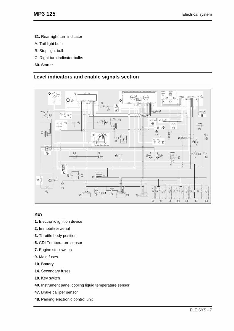
Level indicators and enable signals section
KEY
1. Electronic ignition device
2. Immobilizer aerial
3. Throttle body position
5. CDI Temperature sensor
7. Engine stop switch
9. Main fuses
10. Battery
14. Secondary fuses
18. Key switch
40. Instrument panel cooling liquid temperature sensor
47. Brake calliper sensor
48. Parking electronic control unit
MP3 125 Electrical system
ELE SYS - 7
49. Right wheel revolution sensor
50. Left wheel revolution sensor
51. Potentiometer
52. Rider presence sensor
53. Oil pressure sensor
54. External temperature sensor
56. Instrument panel
57. Fuel level transmitter
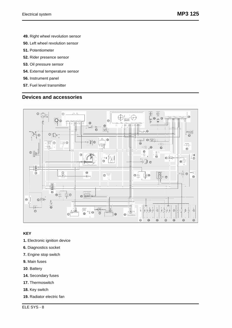
Devices and accessories
KEY
1. Electronic ignition device
6. Diagnostics socket
7. Engine stop switch
9. Main fuses
10. Battery
14. Secondary fuses
17. Thermoswitch
18. Key switch
19. Radiator electric fan
Electrical system MP3 125
ELE SYS - 8
21. Saddle opening receiver
1. Aerial
2. Actuator 1
3. Reset
4. +Battery
6. Key
7. Ground
11. Channel 1/3 selection
12. Alarm code out
22. Saddle opening actuator
23. Reset
25. Wiring for Tom-Tom
27. Wiring for antitheft device
28. Helmet compartment internal light
35. Horn button
38. Helmet compartment light switch
39. Helmet compartment light switch
41. Mode button
42. Locking/unlocking switch
43. Horn remote control
44. Pressure sensor
45. Horn
46. Geared motor
48. Parking electronic control unit
55. Parking brake button
56. Instrument panel
58. Electric pump control device (for scooters with electric pump only)
1. +Key
3. Pump ground connection
4. +Pump
5. Ground
6. Engine revs
59. Fuel pump (for scooters with electric pump only)
MP3 125 Electrical system
ELE SYS - 9

Lights and turn indicators
KEY
7. Engine stop switch
9. Main fuses
10. Battery
14. Secondary fuses
18. Key switch
20. Turn signal switch
24. Hazard button
26. Hazard and turn signal control device
1. Hazard button
2. Left switch
3. Right switch
4. Left turn indicator
5. Right turn indicator
6. Ground
7. Key
8. +Battery
29. Rear left turn indicator
Electrical system MP3 125
ELE SYS - 10

A. Left turn indicator bulbs
B. Stop light bulb
C. Tail light bulb
30. Licence plate lamp
31. Rear right turn indicator
A. Tail light bulb
B. Stop light bulb
C. Right turn indicator bulbs
32. Front left turn indicator
33. Headlight assembly
A. Tail light bulbs
B. Low-beam bulb
C. High-beam bulb
34. Front right turn indicator
36. Remote control headlight
37. Light switch
48. Parking electronic control unit
56. Instrument panel
Checks and inspections
This section is devoted to the checks on the electrical system components.
Immobiliser
The electric ignition system is fed with direct cur-
rent and is protected by an anti-theft immobilizer
integrated to the control unit.
The ignition system consists of:
- electronic control unit
- immobilizer aerial
- master and service keys with built-in transponder
- H.V. coil
- diagnosis led
The diagnosis led also works as a blinking light to
deter theft. This function is activated every time the
key switch is turned to "OFF" and it remains active
48 hours so as not to damage the battery charging
process.
MP3 125 Electrical system
ELE SYS - 11

When the key switch is turned to "ON", this blinking
function is deactivated. A flash then confirms the
system has switched to "ON".
The duration of the flash depends on the electronic
control unit program (see figure).
If the led turns off and remains so when switching
to "ON", it is necessary to check if there is battery
voltage in the electric control unit.
Connect the immobilizer tester to the diagnosis
socket (see ET4 125 manual) located below the
spark plug inspection port.
If the serial led remains off, check the control unit
voltage supply; in order to do this, disconnect the
control unit connector and check if:
- there is battery voltage between the terminal No.
6 (Red/Green) and the ground connection.
- there is battery voltage between the terminal No.
6 (Red/Green) and the terminal No. 9 (Negative)
as shown in the figure.
If no voltage is detected, check the wiring to the
battery positive lead and see if 15A fuse No. 4 is
in good conditions.
- there is battery voltage between the terminal No.
8 (Orange) and the terminal No. 9 (Negative) with
the key switch set to "ON" and the emergency
switch set to "RUN".
If no faults are found, replace the control unit; oth-
erwise check the wiring and the following compo-
nents:
- Engine stop remote control;
- Emergency cut-off switch;
- Key switch contacts.
Electrical system MP3 125
ELE SYS - 12

Virgin circuitIf the ignition system has not been programmed,
the engine can be started but it will run limited to
2000 rpm. When trying to accelerate, some evi-
dent loss of power may be felt.
Program the system with the MASTER (Brown)
and SERVICE (Black) keys as follows:
- Insert the MASTER key, turn it to "ON" and keep
it in that position for 2 seconds (limit values: 1 ÷ 3
seconds).
- Alternately insert all the available black keys and
turn each one of them to "ON" for 2 seconds.
- Insert the MASTER key again and turn it to "ON"
for 2 seconds.
The maximum time to change keys is 10 seconds.
A maximum of 7 (Black) service keys can be pro-
grammed at one time.
Sequence and times must be strictly observed or
it will be necessary to repeat the procedure from
the start.
Once the control unit has been programmed, the
control unit is inseparably matched with the MAS-
TER key transponder.
This matching allows programming further service
keys in case of loss, replacement, etc. Each new
time new data is programmed the previously stor-
ed one is deleted.
If a service key setting is lost, it is essential to
carefully check the efficiency of the high voltage
system:
Shielded cap resistance ~ 5000 Ω.
In any case it is advisable to use resistive spark
plugs.
Diagnostic codesThe flash indicating the switching to "ON" can be followed by a phase of programmed failure warnings.
That is, the led is off for 2 seconds, and then diagnosis codes are transmitted with 0.5-second flashes.
After the failure code indication, a steadily on LED signals that ignition is disabled; see the table:
MP3 125 Electrical system
ELE SYS - 13
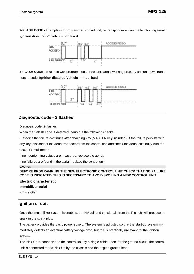
2-FLASH CODE - Example with programmed control unit, no transponder and/or malfunctioning aerial.
Ignition disabled-Vehicle immobilised
3-FLASH CODE - Example with programmed control unit, aerial working properly and unknown trans-
ponder code. Ignition disabled-Vehicle immobilised
Diagnostic code - 2 flashes
Diagnosis code: 2-flashes
When the 2-flash code is detected, carry out the following checks:
- Check if the failure continues after changing key (MASTER key included). If the failure persists with
any key, disconnect the aerial connector from the control unit and check the aerial continuity with the
020331Y multimeter.
If non-conforming values are measured, replace the aerial.
If no failures are found in the aerial, replace the control unit.CAUTIONBEFORE PROGRAMMING THE NEW ELECTRONIC CONTROL UNIT CHECK THAT NO FAILURECODE IS INDICATED. THIS IS NECESSARY TO AVOID SPOILING A NEW CONTROL UNIT
Electric characteristicimmobilizer aerial~ 7 ÷ 9 Ohm
Ignition circuit
Once the immobilizer system is enabled, the HV coil and the signals from the Pick-Up will produce a
spark in the spark plug.
The battery provides the basic power supply. The system is adjusted so that the start-up system im-
mediately detects an eventual battery voltage drop, but this is practically irrelevant for the ignition
system.
The Pick-Up is connected to the control unit by a single cable; then, for the ground circuit, the control
unit is connected to the Pick-Up by the chassis and the engine ground lead.
Electrical system MP3 125
ELE SYS - 14

To avoid disturbances in the ignition system during start-up, it is very important that the engine-chassis
ground connection bonding is efficient.
No spark plug
Once the lack of power to the spark plug has been
detected and the led indicates it can be ignited,
follow this procedure:
- Pick-Up check.
Disconnect the control unit connector and check
that the cable between terminal No. 11 (Green)
and terminal No. 9 (Black) is not interrupted.
Check the Pick-Up and its power line:
Electric characteristicPick-up resistance value
Pick-up resistance value: 105 ÷ 124 Ohm
If a break in the circuit is found, check again the flywheel and the engine ground connectors (see engine
manual). If non-conforming values are detected, replace the Pick-Up, otherwise check the cable har-
ness and the connections. In case conforming values are measured and the wiring and connections
check is OK, try replacing the control unit (without programming) and make sure the failure has been
solved by checking sparks are produced in the spark plug; only then program the control unit. If no
sparks are produced with the new control unit, proceed as follows.
- HV primary coil check
Disconnect the control unit connector and check
that the cable between terminal No. 17 (Violet) and
terminal No. 9 (Black) is not interrupted (see fig-
ure). If non-conforming values are detected, dis-
connect the two connectors on the HV coil and
check its continuity (see figure). If the values are
correct, repair the cable harness and restore the
connections; otherwise, replace the HV coil.
Electric characteristicHigh voltage coil primary resistance value
High voltage coil primary resistance value: 0.4 ÷
0.5 Ohm
HV coil secondary check
MP3 125 Electrical system
ELE SYS - 15

Disconnect the spark plug cap from the HV cable and measure the resistance between the HV cable
terminal and the HV coil negative terminal (see figure). If non-conforming values are measured, replace
the HV coil. To carry out a more complete diagnosis, check the peak voltage with the multimeter adaptor.
Electric characteristicHigh voltage coil secondary resistance value
High voltage coil secondary resistance value: ~ 3000 ± 300 Ohm
- Pick-Up.
Disconnect the control unit connector and connect
the positive wire to connector No. 11 and the neg-
ative wire to connector No. 9 (see figure).
Use the start-up system to run the engine and
measure the voltage produced by the Pick-Up.
Replace Pick-Up if non-conforming values are
measured.
Electric characteristicPick-Up voltage value
Pick-Up voltage value: > 2 Volt
- H.V. coil
With the control unit and HV coil connected, meas-
ure the voltage of the coil primary during the start-
up test with the voltage peak adaptor and con-
necting the positive terminal to the earth one and
the negative to the coil positive connector.
If non-conforming values are measured, replace
the control unit.N.B.
THE PLASTIC CAP OF THE POSITIVE TERMI-NAL ON THE HV COIL PRIMARY IS BLACKAND THE NEGATIVE TERMINAL ONE ISGREEN.
Electric characteristicHigh voltage coil voltage value
Electrical system MP3 125
ELE SYS - 16

High voltage coil voltage value: > 100 Volt
Battery recharge circuit
The recharge system is provided with a three phase alternator with permanent flywheel.
The alternator is directly connected to the voltage regulator.
In turn, the latter is directly connected to earth and to the battery positive passing through the 15A safety
fuse.
The three- phase generator provides good recharge power and at low revs a good compromise is
achieved between generated power and idle stability.
Stator check
Disconnect the connector from the voltage regulator and check there is continuity between any yellow
cable and the other two cables.
Electric characteristicOhm value:
0.7 ÷ 0.9 Ohm
Also check that all yellow cables are insulated from
the ground connection.
If non-conforming values are detected, repeat the
checks directly to the stator. In case of further rep-
etitions of incorrect values replace the stator or
repair the wiring.
MP3 125 Electrical system
ELE SYS - 17
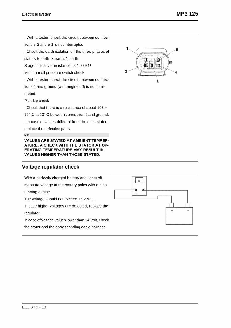
- With a tester, check the circuit between connec-
tions 5-3 and 5-1 is not interrupted.
- Check the earth isolation on the three phases of
stators 5-earth, 3-earth, 1-earth.
Stage indicative resistance: 0.7 - 0.9 Ω
Minimum oil pressure switch check
- With a tester, check the circuit between connec-
tions 4 and ground (with engine off) is not inter-
rupted.
Pick-Up check
- Check that there is a resistance of about 105 ÷
124 Ω at 20° C between connection 2 and ground.
- In case of values different from the ones stated,
replace the defective parts.N.B.
VALUES ARE STATED AT AMBIENT TEMPER-ATURE. A CHECK WITH THE STATOR AT OP-ERATING TEMPERATURE MAY RESULT INVALUES HIGHER THAN THOSE STATED.
Voltage regulator check
With a perfectly charged battery and lights off,
measure voltage at the battery poles with a high
running engine.
The voltage should not exceed 15.2 Volt.
In case higher voltages are detected, replace the
regulator.
In case of voltage values lower than 14 Volt, check
the stator and the corresponding cable harness.
Electrical system MP3 125
ELE SYS - 18

Recharge system voltage check
Connect an ammeter induction clamp to the volt-
age regulator positive terminal, measure the bat-
tery voltage and turning on the vehicles lights with
engine off, wait for the voltage to set at about 12
V. Start the engine and measure the current gen-
erated by the system with lights on and a high
running engine.
In case the generated current value is lower than
10A, repeat the test using a new regulator and/
stator alternatively.
Choke Inspection
Refer to the engine section to check the resistance
and operating conditions of the component. As re-
gards voltage supply, keep the connector connec-
ted to the system and check that the two terminals
receive battery voltage when the engine is on (see
figure).
If voltage is detected, replace the automatic starter
as it is surely failing.
If no voltage is detected, connect the multimeter
negative terminal to the earth terminal and the
positive terminal to the automatic starter orange
cable; with the key switch set to «ON» check
whether there is battery voltage; if there is no volt-
age, check the wiring connections to the key
switch and that the 15A fuse works properly.
If there is voltage, check again the ignition control
unit connector. After disconnecting the starter,
start up the engine and keep it at idle speed; then
check there is voltage connecting the multimeter
MP3 125 Electrical system
ELE SYS - 19

positive probe to terminal No. 8 (Orange), and the
negative one to terminal No. 10 (Brown) (see fig-
ure).
Replace the control unit if there is no voltage; oth-
erwise, check the wiring connections between the
starter and the control unit.
Lights list
LIGHT BULBS TABLE
Specification Desc./Quantity1 Low-beam bulb Type: HALOGEN (H1)
Power: 12V - 55WQuantity: 1
2 High-beam light bulb Type: HALOGEN (H1)Power: 12V - 55W
Quantity: 13 Helmet compartment light bulb Type: CYLINDRIC
Power: 12V - 5WQuantity: 1
4 Rear turn indicator bulb Type: ALL GLASSPower: 12V - 5W
Quantity: 2 RHS + 2 LHS5 Rear tail light bulb Type: ALL GLASS
Power: 12V - 5WQuantity: 1 RHS + 1 LHS
6 Stop light bulb Type: SPHERICALPower: 12V - 10W
Quantity: 27 License plate light bulb Type: ALL GLASS
Power: 12V - 5WQuantity: 1
8 Front turn indicator bulb Type: ALL GLASSPower: 12V - 10W
Quantity: 1 RHS + 1 LHS9 Front tail light bulb Type: ALL GLASS
Power: 12V - 3WQuantity: 1 RHS + 1 LHS
10 Instrument panel bulb Type: ALL GLASSPower: 12V - 2W
Quantity: 4
Electrical system MP3 125
ELE SYS - 20

Fuses
The electrical system has eleven fuses divided into
two fuse boxes to protect the different installation
circuits. One of them is inside the battery compart-
ment and the other is at the right internal side of
the footrest. To be able to reach them, loosen the
screw "A" and remove the plastic cover. The chart
shows the position and characteristics of the fuses
in the vehicle.CAUTION
BEFORE REPLACING THE BLOWN FUSE,FIND AND SOLVE THE FAILURE THATCAUSED IT TO BLOW. NEVER TRY TO RE-PLACE THE FUSE WITH ANY OTHER MATERI-AL (E.G., A PIECE OF ELECTRIC WIRE).
FUSE CHART
Specification Desc./Quantity1 Fuse No. 1 Capacity: 10A
Protected circuits:from the battery: headlight remote control
Location:battery compartment2 Fuse No. 2 Capacity: 7.5 A
Protected circuits:from the battery: saddle opening receiver,
hazard and turn indicator control device, anti-theft device pre-installation, instrument pan-
el, helmet compartment lightingLocation:battery compartment
3 Fuse No. 3 Capacity: 15 AProtected circuits:
live: parking control ECU, fuses 8, 9 and 10Location:battery compartment
4 Fuse No. 4 Capacity: 15 AProtected circuits:
from the battery: voltage regulator, electricfan, electronic ignition device
live: engine stop switch, starter, electronic ig-nition device, TPS, fuses 7 and 11
Location:battery compartment5 Fuse No. 5 Capacity: 20A
Protected circuits:
MP3 125 Electrical system
ELE SYS - 21

Specification Desc./Quantityfrom the battery: parking control ECU
Location:battery compartment6 Fuse No. 6 Capacity: 4A
Protected circuits:start-up, stop lights.Location:footrest
7 Fuse No. 7 Capacity: 4AProtected circuits:panel lighting, tail lights,
license plate lightLocation:footrest
8 Fuse No. 8 Capacity: 7.5 AProtected circuits:lights switch, horn, wiring
for Tom-TomLocation:footrest
9 Fuse No. 9 Capacity: 7.5 AProtected circuits:saddle opening receiver,hazard and turn indicator control device, anti-
theft device pre-installation, turn indicatorswitch, instrument panel, horn remote control
Location:footrest10 Fuse No. 10 Capacity: 7.5 A
Protected circuits:headlight remote controlLocation:footrest
11 Fuse No. 11 Capacity: 3AProtected circuits:electric pump control de-
viceLocation:footrest
Dashboard
A = Led immobilizer / anti-theft device
B= Speedometer with twin scale (km/h and mph)
C = CLOCK switch
D = Digital display
E = Front suspension locking system warning light
(if available)
F = SET switch
G = Rpm indicator
H = Fuel gauge
I = Warning light for helmet compartment courtesy
light on
L = Engine control telltale light and injection sys-
tem failure warning light
M = Low fuel warning light
N = Engine stop warning light
D= Turn indicator warning light
P = Low oil pressure warning light
Electrical system MP3 125
ELE SYS - 22

Q = Front suspension locking system failure warn-
ing light (if available)
R = Warning light for parking brake engaged
C = High-beam warning light
Pushing the «CLOCK» button for less than 1 second displays the following sequence:
• TIME
• DATE
To set the clock push and hold the «CLOCK» button longer than 3 seconds.
The numbers showing the hours will begin flashing.
Set the hour using the «SET» button. Push the «CLOCK» button again and the minutes numbers start
flashing.
Set the minutes using the «SET»button. Push the «CLOCK» button again and the day numbers start
flashing.
Set the day with the «SET» button. Push the «CLOCK» button again and the month numbers start
flashing.
Set the month with the «SET» button. Push the «CLOCK» button again and the year numbers start
flashing.
Set the year with the «SET» button. Press the «CLOCK » button again for 4 seconds to exit the ad-
justment menu.
During the reset process, not pressing any buttons for a period longer than 8 seconds ends the process
automatically and the display shows the modified time.
Sealed batteryIf the vehicle is provided with a sealed battery, the only maintenance required is the check of its charge
and recharging, if necessary.
These operations should be carried out before delivering the vehicle, and on a six-month basis while
the vehicle is stored in open circuit.
Besides, upon pre-delivery it is therefore necessary to check the battery charge and recharge it, if
required, before storing the vehicle and, afterwards, every six months.
INSTRUCTIONS FOR THE BATTERY REFRESH AFTER OPEN-CIRCUIT STORAGE
1) Voltage check
Before installing the battery on the vehicle, check the open circuit voltage with a regular tester.
- If voltage exceeds 12.60 V, the battery can be installed without any renewal recharge.
- If voltage is below 12.60 V, a renewal recharge is required as explained in 2).
2) Constant voltage battery charge mode
- Constant voltage charge equal to 14.40 ÷ 14.70V
-Initial charge voltage equal to 0.3 ÷ 0.5 for Nominal capacity
- Charge time:
MP3 125 Electrical system
ELE SYS - 23

10 to 12 h recommended
Minimum 6 h
Maximum 24 h
3) Constant current battery charge mode
-Charge current equal to 1/10 of the nominal capacity of the battery
- Charge time: 5 hCAUTION
NEVER USE FUSES WITH A CAPACITY HIGHER THAN THE RECOMMENDED CAPACITY. USINGA FUSE OF UNSUITABLE RATING MAY SERIOUSLY DAMAGE THE VEHICLE OR EVEN CAUSEA FIRE.CHARGE THE BATTERY BEFORE USE TO ENSURE OPTIMUM PERFORMANCE. INADEQUATECHARGING OF THE BATTERY WITH A LOW ELECTROLYTE LEVEL BEFORE IT IS FIRST USEDSHORTENS THE LIFE OF THE BATTERY.IF THE VEHICLE IS NOT USED FOR SOME TIME (1 MONTH OR MORE) THE BATTERY NEEDSTO BE RECHARGED PERIODICALLY. THE BATTERY RUNS DOWN COMPLETELY IN THECOURSE OF THREE MONTHS. IF IT IS NECESSARY TO REFIT THE BATTERY IN THE VEHICLE,BE CAREFUL NOT TO REVERSE THE CONNECTIONS TAKING INTO ACCOUNT THAT THEGROUND WIRE (BLACK) MARKED(-) MUST BE CONNECTED TO THE - NEGATIVE TERMINALWHILE THE OTHER TWO RED WIRES MARKED (+) MUST BE CONNECTED TO THE TERMINALMARKED WITH THE +POSITIVE SIGNWARNING
WHEN THE BATTERY IS REALLY FLAT (WELL BELOW 12.6V) IT MIGHT OCCUR THAT 5 HOURSOF RECHARGING ARE NOT ENOUGH TO ACHIEVE OPTIMAL PERFORMANCE.GIVEN THESE CONDITIONS IT IS HOWEVER ESSENTIAL NOT TO EXCEED 8 HOURS OF CON-TINUOUS RECHARGING SO AS NOT TO DAMAGE THE BATTERY ITSELF.
Dry-charge batteryCOMMISSIONING A NEW DRY-CHARGED BATTERY
- Remove the battery air pipe stop cap and each single element caps.
- Fill the battery with electrolyte of 1.270+/-0.01 kg/l density (corresponding to 31+/-1 Bé) with an am-
bient temperature not below 15°C, until it reaches the upper level indicated on the block.
- Tilt the battery slightly to remove any air bubbles formed during filling.
- Place the caps on each single element filling holes without screwing them and leave the battery to
rest. During this stage, the battery is subjected to a gasification phenomenon and temperature increa-
ses.
- Let it rest until it reaches ambient temperature (this stage can take up to 60 minutes).
- Tilt the battery slightly to facilitate the elimination of any gas bubbles present inside; restore the level
using the same filling electrolyte
Note: This is the last time that electrolyte can be added. Future top-ups should be done only with distilled
water;
- Before 24 hours elapse, recharge the battery following these steps:
- Connect the battery charger terminals observing the correct polarity;
- Wit the battery charger drw. 020333Y and/or drw. 020334Y operate the battery charger control by
selecting the position corresponding to that capacity;
Electrical system MP3 125
ELE SYS - 24
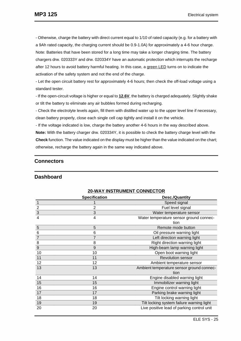
- Otherwise, charge the battery with direct current equal to 1/10 of rated capacity (e.g. for a battery with
a 9Ah rated capacity, the charging current should be 0.9-1.0A) for approximately a 4-6 hour charge.
Note: Batteries that have been stored for a long time may take a longer charging time. The battery
chargers drw. 020333Y and drw. 020334Y have an automatic protection which interrupts the recharge
after 12 hours to avoid battery harmful heating. In this case, a green LED turns on to indicate the
activation of the safety system and not the end of the charge.
- Let the open circuit battery rest for approximately 4-6 hours; then check the off-load voltage using a
standard tester.
- If the open-circuit voltage is higher or equal to 12.6V, the battery is charged adequately. Slightly shake
or tilt the battery to eliminate any air bubbles formed during recharging.
- Check the electrolyte levels again, fill them with distilled water up to the upper level line if necessary,
clean battery properly, close each single cell cap tightly and install it on the vehicle.
- If the voltage indicated is low, charge the battery another 4-6 hours in the way described above.
Note: With the battery charger drw. 020334Y, it is possible to check the battery charge level with the
Check function. The value indicated on the display must be higher than the value indicated on the chart;
otherwise, recharge the battery again in the same way indicated above.
Connectors
Dashboard
20-WAY INSTRUMENT CONNECTORSpecification Desc./Quantity
1 1 Speed signal2 2 Fuel level signal3 3 Water temperature sensor4 4 Water temperature sensor ground connec-
tion5 5 Remote mode button6 6 Oil pressure warning light7 7 Left direction warning light8 8 Right direction warning light9 9 High-beam lamp warning light10 10 Open boot warning light11 11 Revolution sensor12 12 Ambient temperature sensor13 13 Ambient temperature sensor ground connec-
tion14 14 Engine disabled warning light15 15 Immobilizer warning light16 16 Engine control warning light17 17 Parking brake warning light18 18 Tilt locking warning light19 19 Tilt locking system failure warning light20 20 Live positive lead of parking control unit
MP3 125 Electrical system
ELE SYS - 25

12-WAY INSTRUMENT CONNECTORSpecification Desc./Quantity
1 5 Lighting2 6 Battery positive3 11 Earth4 12 Live positive lead
Remote seat opening
Zeroing
- Remove the left side fairing to access the saddle
opening receiver control unit indicated in the pho-
tograph
- Remove the metal terminal and connect it to a
good earth point, or to terminal 7 (black), for at
least 10 seconds.
- In this operation all the remote controls stored in
the control unit will be deleted.WARNING
THE CONTROL UNIT CAN PROGRAMME UPTO 8 REMOTE CONTROLS.
Programming
Follow these steps to program the remote controls:
1. Insert the remote control key to be programmed in the steering lock key block.
Electrical system MP3 125
ELE SYS - 26

2. Turn the key to «ON», press the button on the remote control, release the button, turn the key back
to «OFF» from the «ON» position, all within 4 seconds.
3 Wait 1 to 8 seconds.
4. Repeat steps 2 and 3 for 4 times without removing the key.
The control unit confirms the programming has been successfully executed by opening the saddle.WARNING
TO STORE THE OTHER REMOTE CONTROLS TO MEMORY, (MAXIMUM 8), YOU NEED TO RE-PEAT THE WHOLE PROCEDURE AGAIN. FAILURE TO CARRY OUT THESE OPERATIONSWITHIN THE INDICATED TIMES WILL RESULT IN THE AUTOMATIC CANCELLATION OF THEPROCESS FOR PROGRAMMING THE REMOTE-CONTROLLED KEYS.WARNING
AVOID PRESSING THE REMOTE CONTROL BUTTON MORE THAN ONCE WHEN FAR AWAYFROM THE SCOOTER. THE SYNCHRONISM BETWEEN THE REMOTE CONTROL AND THE RE-CEIVER CAN BE IMPAIRED. SHOULD THIS BE THE CASE, REPEAT THE PROGRAMMINGPROCEDURE. DO NOT KEEP THE REMOTE CONTROL IN PLACES WITH TEMPERATURES EX-CEEDING 60° C THE BATTERY WILL RUN DOWN TOO QUICKLY.WARNING
TO AVOID BATTERY DISCHARGE, THE SADDLE OPENING REMOTE CONTROL RADIO RE-CEIVER DEACTIVATES 7 DAYS AFTER THE LAST TIME THE VEHICLE WAS SHUT OFF.JUST TURN THE KEY TO «ON» TO REACTIVATE THE RECEIVER.
MP3 125 Electrical system
ELE SYS - 27

Electrical system MP3 125
ELE SYS - 28

INDEX OF TOPICS
ENGINE FROM VEHICLE ENG VE

This section describes the operations to carry out when removing the engine from the vehicle.
Exhaust assy. Removal
- Remove the Lambda probe from its support and
disconnect it.
- Undo the two exhaust manifold fixings on the
head. To undo the nuts fixing the muffler flange to
the head properly, you must use a jointed wrench
that enables you to get at the right nut as well, ac-
cording to the direction of travel, that is difficult to
get at with a traditional straight wrench.
- Undo the three screws fixing the muffler to the
support arm.
Remove the full muffler unit.
Remove the lambda probe from the manifold.
Engine from vehicle MP3 125
ENG VE - 2

CAUTION: SHOULD IT BE NECESSARY TO REMOVE ONLY THE MUFFLER TIP, ALWAYS RE-
PLACE THE GRAPHITE GASKET BETWEEN STUB AND TIP.
Removal of the engine from the vehicle
- Disconnect the battery
- Remove the engine cover inside the helmet com-
partment
- Remove the side panels
Remove the full muffler assembly.CAUTION
THIS OPERATION MUST BE CARRIED OUTWHEN THE ENGINE IS COLD.
- Remove the rear wheel.
- Remove the pipe feeding coolant into the pump
as shown in the photograph and then empty the
system.
- Remove the engine coolant outlet pipe as indi-
cated.
- Disconnect the fuel delivery and return pipes from
the injector by removing the screw locking the re-
taining clip.
- Disconnect the injector wiring and the throttle
body control unit wiring.
MP3 125 Engine from vehicle
ENG VE - 3

- Remove the coolant outlet pipe from the motor
as indicated.
- Remove the spark plug caps.
- Remove the coolant temperature sensor con-
nector indicated in the photo.
- Remove the throttle cable from the throttle body
by undoing the nut shown in the photo.
- Remove the positive and negative wiring from the
starter motor as shown in the photo.
Engine from vehicle MP3 125
ENG VE - 4
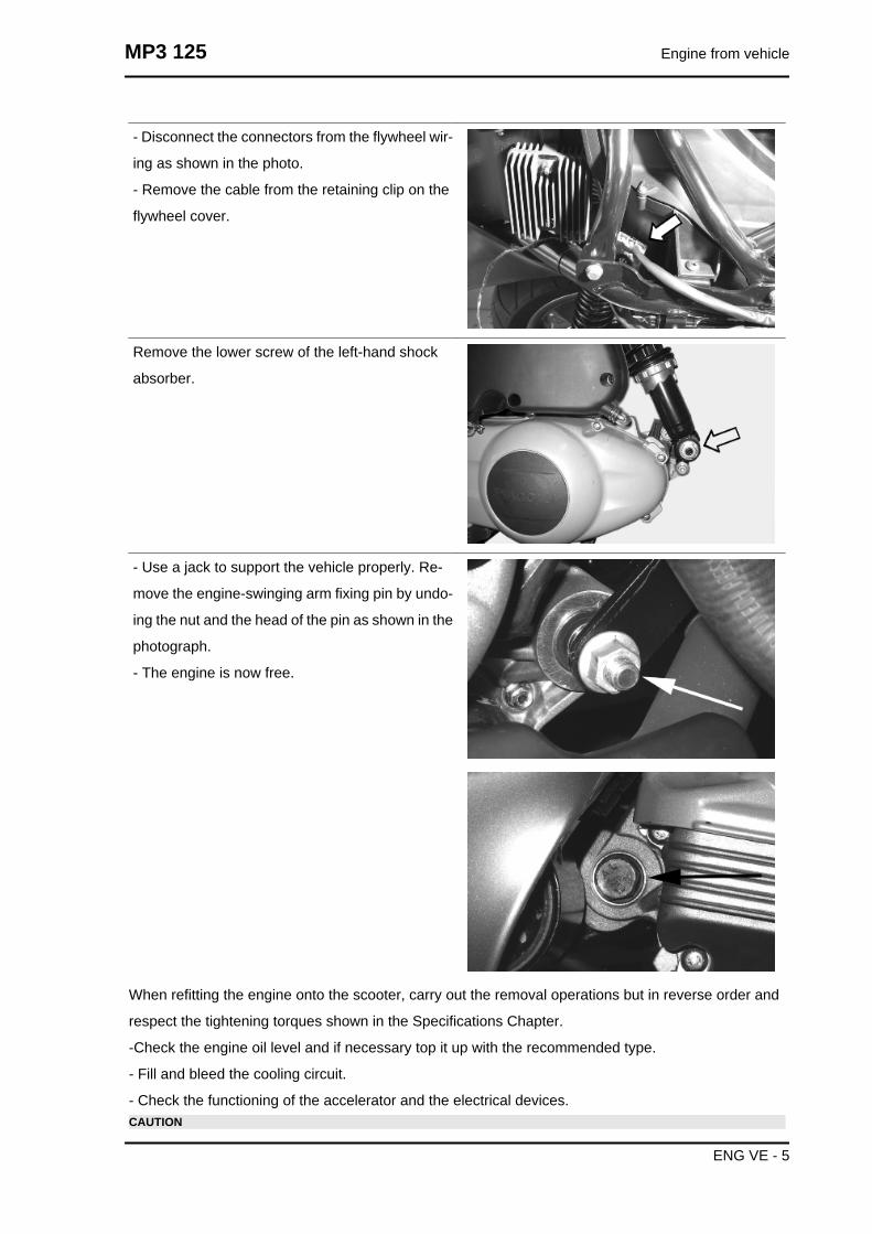
- Disconnect the connectors from the flywheel wir-
ing as shown in the photo.
- Remove the cable from the retaining clip on the
flywheel cover.
Remove the lower screw of the left-hand shock
absorber.
- Use a jack to support the vehicle properly. Re-
move the engine-swinging arm fixing pin by undo-
ing the nut and the head of the pin as shown in the
photograph.
- The engine is now free.
When refitting the engine onto the scooter, carry out the removal operations but in reverse order and
respect the tightening torques shown in the Specifications Chapter.
-Check the engine oil level and if necessary top it up with the recommended type.
- Fill and bleed the cooling circuit.
- Check the functioning of the accelerator and the electrical devices.CAUTION
MP3 125 Engine from vehicle
ENG VE - 5

PAY PARTICULAR ATTENTION TO POSITIONING THE THROTTLE COMMAND TRANSMISSIONPROPERLY.
Engine from vehicle MP3 125
ENG VE - 6

INDEX OF TOPICS
ENGINE ENG
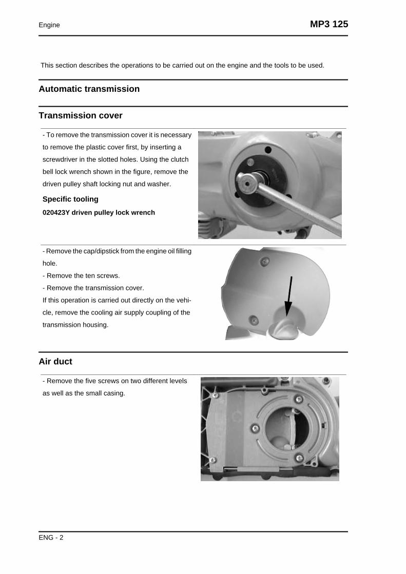
This section describes the operations to be carried out on the engine and the tools to be used.
Automatic transmission
Transmission cover
- To remove the transmission cover it is necessary
to remove the plastic cover first, by inserting a
screwdriver in the slotted holes. Using the clutch
bell lock wrench shown in the figure, remove the
driven pulley shaft locking nut and washer.
Specific tooling020423Y driven pulley lock wrench
- Remove the cap/dipstick from the engine oil filling
hole.
- Remove the ten screws.
- Remove the transmission cover.
If this operation is carried out directly on the vehi-
cle, remove the cooling air supply coupling of the
transmission housing.
Air duct
- Remove the five screws on two different levels
as well as the small casing.
Engine MP3 125
ENG - 2

- To remove the intake throat on the transmission
cover, just remove the 2 fixing screws indicated in
the figure.
Removing the driven pulley shaft bearing
- Remove the clip from the inside of the cover.
- Remove the bearing from the crankcase by
means of:
Specific tooling020376Y Adaptor handle
020375Y Adaptor 28 x 30 mm
020412Y 15 mm guide
Refitting the driven pulley shaft bearing
- Slightly heat the crankcase from the inside so as
not to damage the painted surface.
- Insert the bearing in its seat.
- Refit the Seeger ring.CAUTION
USE AN APPROPRIATE REST SURFACE TOAVOID DAMAGING THE COVER PAINT.N.B.
ALWAYS REPLACE THE BEARING WITH ANEW ONE UPON REFITTING.
Specific tooling020376Y Adaptor handle
020357Y 32 x 35 mm adaptor
020412Y 15 mm guide
MP3 125 Engine
ENG - 3

Removing the driven pulley
- Remove the spacer, the clutch bell and the whole
driven pulley unit.N.B.
THE UNIT CAN ALSO BE REMOVED WITH THEDRIVING PULLEY MOUNTED.
Inspecting the clutch drum
- Check that the clutch bell is not worn or damaged.
- Measure the clutch bell inside diameter.
CharacteristicMax. value clutch bell
Max. value: Ø 134.5 mm
Clutch bell standard value
Standard value: Ø 134 - 134.2 mm
Checking the bell working surface eccentricity
- Install the bell on a driven pulley shaft using 2
bearings (inner diameter 15 and 17 mm).
- Lock with the original spacer and nut.
- Place the bell/shaft assembly on the support to
check the crankshaft alignment.
Engine MP3 125
ENG - 4

- Using a feeler pin gauge and the magnetic base,
measure the bell eccentricity.
- Repeat the measurement in 3 positions (Central,
internal, external).
- If faults are found, replace the bell.
Specific tooling020074Y Support base for checking crankshaftalignment
020335Y Magnetic support for dial gauge
Characteristicclutch bell inspection: Limit eccentricity.
Admissible limit eccentricity: 0.15 mm
Removing the clutch
Clutch removal (125 cm³ H2O)
Fit the driven pulley spring compressor specific
tool with medium length pins screwed in position
F from the tool internal side.
- Insert the adapter ring 8 in the pins.
- Assemble the driven pulley unit on the tool intro-
ducing the rivets heads in the adapter ring.
- Make sure that the clutch is perfectly inserted into
the adapter ring before proceeding to loosen/tight-
en the clutch nut.
- Use the special 46x55 wrench component n°9 to
remove the nut fixing the clutch in place.
- Separate the driven pulley components (Clutch,
fan and spring with plastic fitting).CAUTION
THE TOOL MUST BE FIRMLY FIXED IN THECLAMP AND THE CENTRAL SCREW MUST BEBROUGHT INTO CONTACT WITH THE TOOL.EXCESSIVE TORQUE CAN CAUSE THE SPE-CIFIC TOOL TO BUCKLE.
Specific tooling020444Y009 46x55 Wrench
020444Y010 adapter ring
MP3 125 Engine
ENG - 5
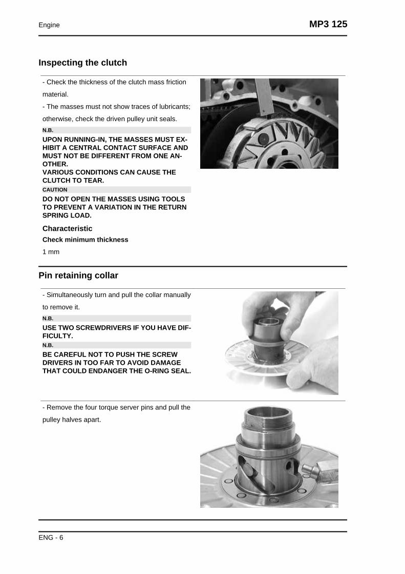
Inspecting the clutch
- Check the thickness of the clutch mass friction
material.
- The masses must not show traces of lubricants;
otherwise, check the driven pulley unit seals.N.B.
UPON RUNNING-IN, THE MASSES MUST EX-HIBIT A CENTRAL CONTACT SURFACE ANDMUST NOT BE DIFFERENT FROM ONE AN-OTHER.VARIOUS CONDITIONS CAN CAUSE THECLUTCH TO TEAR.CAUTION
DO NOT OPEN THE MASSES USING TOOLSTO PREVENT A VARIATION IN THE RETURNSPRING LOAD.
CharacteristicCheck minimum thickness
1 mm
Pin retaining collar
- Simultaneously turn and pull the collar manually
to remove it.N.B.
USE TWO SCREWDRIVERS IF YOU HAVE DIF-FICULTY.N.B.
BE CAREFUL NOT TO PUSH THE SCREWDRIVERS IN TOO FAR TO AVOID DAMAGETHAT COULD ENDANGER THE O-RING SEAL.
- Remove the four torque server pins and pull the
pulley halves apart.
Engine MP3 125
ENG - 6

Removing the driven half-pulley bearing
- Check there are no signs of wear and/or noisi-
ness; - Replace with a new one if there are.
- Remove the retaining ring using two flat blade
screwdrivers.
- Support the pulley bushing adequately from the
threaded side using a wooden surface.
- Using a hammer and pin, knock the ball bearing
out as shown in the figure.
- Support the pulley properly using the bell as shown in the figure.
Specific tooling001467Y035 Belle for OD 47-mm bearings
- Remove the roller bearing using the modular
punch.
Specific tooling020376Y Adaptor handle
020456Y Ø 24 mm adaptor
020363Y 20 mm guide
Inspecting the driven fixed half-pulley
- Measure the outer diameter of the pulley bushing.
- Check the contact surface with the belt to make
sure there are no flaws.
CharacteristicHalf-pulley standard diameter
Standard diameter: Ø 40.985 mm
Half-pulley minimum diameter
Minimum admissible diameter Ø 40.96 mm
MP3 125 Engine
ENG - 7

Inspecting the driven sliding half-pulley
- Remove the two internal grommets and the two
O-rings.
- Measure the movable half-pulley bushing inside
diameter.
CharacteristicMovable driven half-pulley max. diameter
Max. diameter admitted: Ø 41.08 mm
Movable driven half-pulley standard diameter
Standard diameter: Ø 41.000 ÷ 41.035 mm
- Remove the two internal grommets and the two
O-rings.
- Measure the movable half-pulley bushing inside
diameter.
- Check that the faying surface with the belt is not
abnormally worn.
- Check the riveted joints are functional.
- Check the evenness of the belt faying surface.
MOVABLE DRIVEN HALF-PULLEY DIMENSIONSSpecification Desc./Quantity
Wear limit 0.3 mmstandard diameter Diameter 41.000 - 41.035 mm
maximum allowable diameter Ø 41.08 mm
- Remove the belt and slide the movable half-pulley with the relevant bush, taking care of the falling
free assembled rollers.
- Remove the return rollers plate with the relative guide pads.
Engine MP3 125
ENG - 8

Refitting the driven half-pulley bearing
- Support the pulley bushing adequately from the
threaded side using a wooden surface.
- Fit a new roller sleeve as in the figure.
- For the fitting of the new ball bearing, follow the
example in the figure using a modular punch.
- Fit the clip.N.B.
FIT THE BALL BEARING WITH THE SHIELDVISIBLE.
Specific tooling020376Y Adaptor handle
020375Y Adaptor 28 x 30 mm
020424Y Driven pulley roller casing fittingpunch
Refitting the driven pulley
- Insert the new oil guards and O-rings on the mov-
able half-pulley.
- Lightly grease the O-rings (A) shown in the figure.
MP3 125 Engine
ENG - 9

- Insert the new oil guards and O-rings on the mov-
able half-pulley.
- Lightly grease the O-rings (A) shown in the figure.
- Fit the half-pulley over the bushing using the ap-
propriate tool
- Check that the pins are not worn and proceed to
refitting them in their slots.
- Refit the torque server closure collar.
Using a curved-spout grease gun, lubricate the
driven pulley assembly with approximately 6 g of
grease. Apply the grease through one of the holes
in the bushing until it comes out through the hole
on the opposite side. This operation is necessary
to avoid the presence of grease beyond the O-
rings.N.B.
THE TORQUE SERVER CAN BE GREASEDWHETHER WITH BEARINGS FITTED ORWHEN THEY ARE BEING REPLACED; UNDER-TAKING THE OPERATION WHEN THE BEAR-INGS ARE BEING SERVICED MIGHT BE EAS-IER.
Specific tooling020263Y Sheath for driven pulley fitting
Recommended productsAGIP GREASE SM 2 Grease for the tone wheelrevolving ring
Soap-based lithium grease containing NLGI 2 Mo-
lybdenum disulphide; ISO-L-XBCHB2, DIN
KF2K-20
Engine MP3 125
ENG - 10
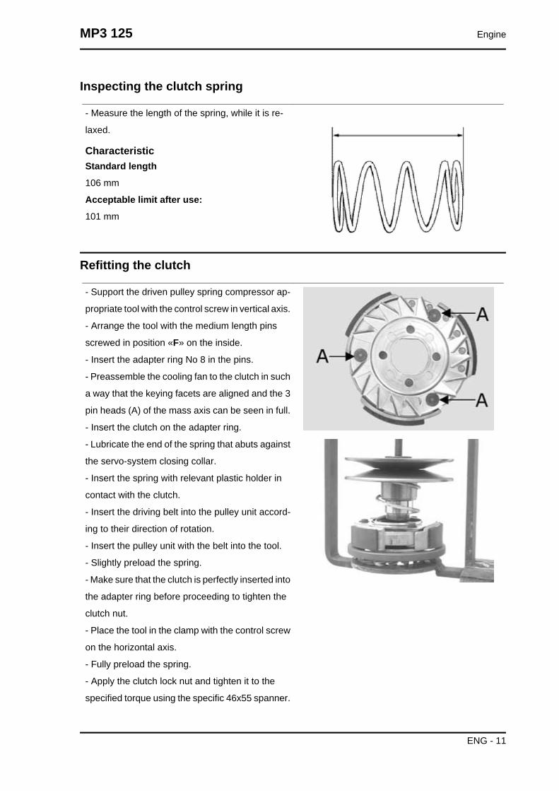
Inspecting the clutch spring
- Measure the length of the spring, while it is re-
laxed.
CharacteristicStandard length
106 mm
Acceptable limit after use:
101 mm
Refitting the clutch
- Support the driven pulley spring compressor ap-
propriate tool with the control screw in vertical axis.
- Arrange the tool with the medium length pins
screwed in position «F» on the inside.
- Insert the adapter ring No 8 in the pins.
- Preassemble the cooling fan to the clutch in such
a way that the keying facets are aligned and the 3
pin heads (A) of the mass axis can be seen in full.
- Insert the clutch on the adapter ring.
- Lubricate the end of the spring that abuts against
the servo-system closing collar.
- Insert the spring with relevant plastic holder in
contact with the clutch.
- Insert the driving belt into the pulley unit accord-
ing to their direction of rotation.
- Insert the pulley unit with the belt into the tool.
- Slightly preload the spring.
- Make sure that the clutch is perfectly inserted into
the adapter ring before proceeding to tighten the
clutch nut.
- Place the tool in the clamp with the control screw
on the horizontal axis.
- Fully preload the spring.
- Apply the clutch lock nut and tighten it to the
specified torque using the specific 46x55 spanner.
MP3 125 Engine
ENG - 11
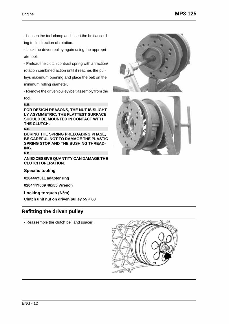
- Loosen the tool clamp and insert the belt accord-
ing to its direction of rotation.
- Lock the driven pulley again using the appropri-
ate tool.
- Preload the clutch contrast spring with a traction/
rotation combined action until it reaches the pul-
leys maximum opening and place the belt on the
minimum rolling diameter.
- Remove the driven pulley /belt assembly from the
tool.N.B.
FOR DESIGN REASONS, THE NUT IS SLIGHT-LY ASYMMETRIC; THE FLATTEST SURFACESHOULD BE MOUNTED IN CONTACT WITHTHE CLUTCH.N.B.
DURING THE SPRING PRELOADING PHASE,BE CAREFUL NOT TO DAMAGE THE PLASTICSPRING STOP AND THE BUSHING THREAD-ING.N.B.
AN EXCESSIVE QUANTITY CAN DAMAGE THECLUTCH OPERATION.
Specific tooling020444Y011 adapter ring
020444Y009 46x55 Wrench
Locking torques (N*m)Clutch unit nut on driven pulley 55 ÷ 60
Refitting the driven pulley
- Reassemble the clutch bell and spacer.
Engine MP3 125
ENG - 12

Drive-belt
• Check that the driving belt is not dam-
aged.
• Check the width of the belt is adequate.
CharacteristicDriving belt - standard width:
22.5 ± 0.2 mm
Driving belt - minimum width:
21.5 mm
During the wear checks foreseen in the scheduled
maintenance services at 6,000 km; 18,000 km;
etc., check that the rim bottom of the toothing does
not show signs of incisions or cracking (see figure):
The rim bottom of the tooth must not have incisions
or cracking; if it does, change the belt.
Removing the driving pulley
- With the appropriate tool, remove the nut with the
built-in Belleville washer, the drive common to the
kick-starter version, and the steel washer.
- Remove the fixed driving half-pulley.
- Remove the steel washer separating from the
bushing.
Specific tooling020368Y driving pulley lock wrench
MP3 125 Engine
ENG - 13

Inspecting the rollers case
- Check that the internal bushing shown in the fig-
ure is not abnormally worn and measure inner
diameter A.
- Measure the pulley sliding bushing outside di-
ameter shown in the figure.
- Check that the rollers are not damaged or worn.
- Check the guide shoes for the variator back-plate
are not worn.
- Check the wear of the roller housings and of the
belt contact surfaces on both pulley halves.
- Check that stationary driving pulley does not
show signs of abnormal wear on the grooved edge
and on the surface in contact with the belt.
- Check that the O-ring is not pushed out of shape.CAUTION
DO NOT LUBRICATE OR CLEAN SINTEREDBUSHINGS
CharacteristicRoller: Minimum diameter permitted
Ø 18.5 mm
Sliding bushing: Minimum admissible diame-ter
Ø 25.95 mm
Movable driving half-pulley bushing: Maxi-mum allowable diameter
Ø 26.12 mm
Roller: Standard Diameter
Ø 18.9 ÷ 19.1 mm
Sliding bushing: Standard Diameter
Ø 25.959 ÷ 25.98 mm
Movable driving half-pulley bushing: StandardDiameter
26.000 - 26.021 mm
Engine MP3 125
ENG - 14
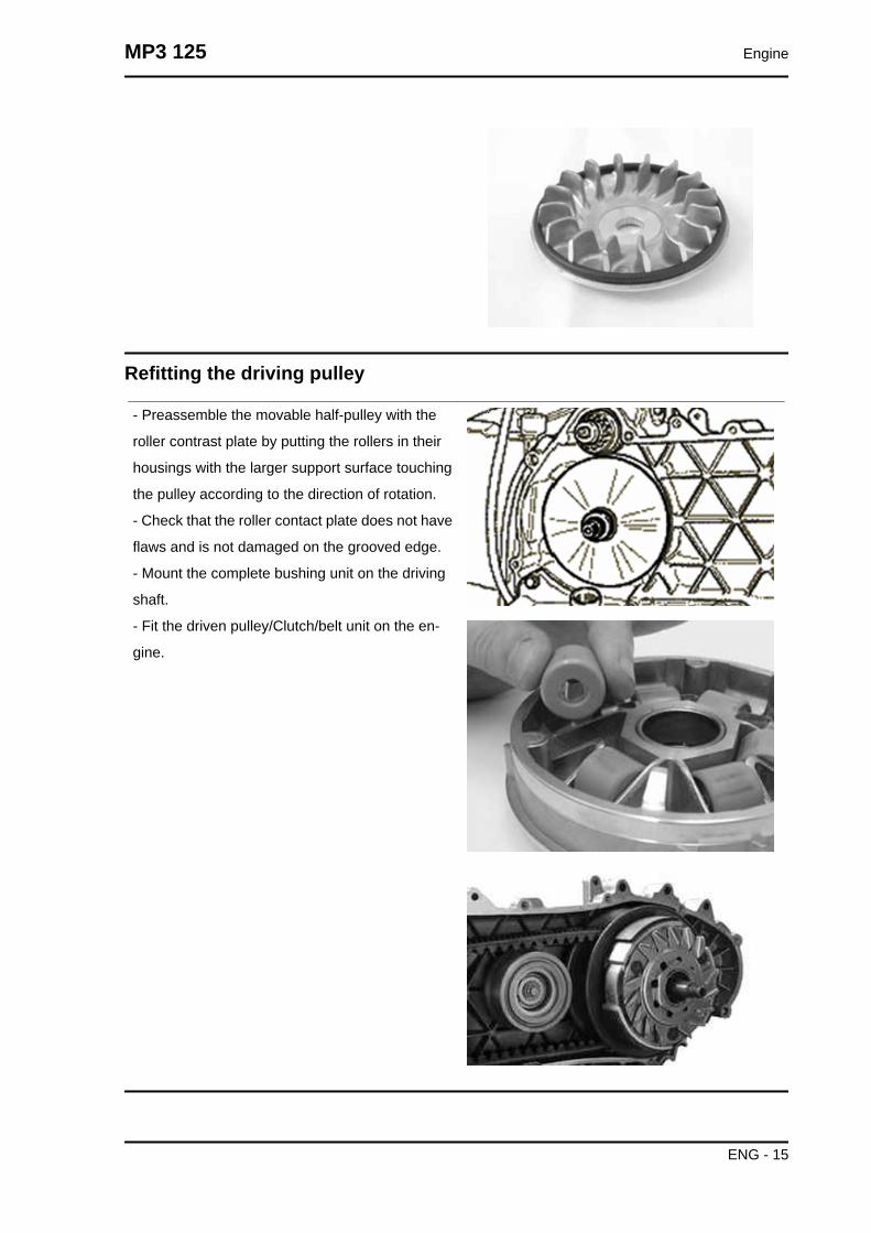
Refitting the driving pulley
- Preassemble the movable half-pulley with the
roller contrast plate by putting the rollers in their
housings with the larger support surface touching
the pulley according to the direction of rotation.
- Check that the roller contact plate does not have
flaws and is not damaged on the grooved edge.
- Mount the complete bushing unit on the driving
shaft.
- Fit the driven pulley/Clutch/belt unit on the en-
gine.
MP3 125 Engine
ENG - 15

- Correctly refit the previously removed Bendix
back to its position.
- Reassemble the parts of the unit (internal lining,
fixed half-pulley, external lining, drive and nut),
spread Loctite 243 Quick Set threadlock on the
thread and tighten the nut to the prescribed torque.
- Avoid the half-pulley rotation with the appropriate
stop key tool..
- Rotate the engine manually until the belt is slight-
ly taut.CAUTION
IT IS EXTREMELY IMPORTANT THAT THEBELT IS PERFECTLY FREE WHEN THE FIXEDDRIVING HALF-PULLEY IS ASSEMBLED. THISIS TO AVOID CARRYING OUT A WRONGTIGHTENING OF THE DRIVING HALF-PULLEY.
Specific tooling020368Y driving pulley lock wrench
Locking torques (N*m)Drive pulley nut 75 ÷ 83
Refitting the transmission cover
- Check the presence of the 2 centring dowels and
the correct installation of the sealing gasket for the
oil sump on the transmission cover.
- Replace the cover tightening the 10 screws at the
specified torque.
- Refit the oil loading cap/bar.
- refit the steel washer and the driven pulley nut.
- Tighten the nut to the prescribed torque using the
lock wrench and the torque wrench tools.
- Replace the plastic cover.
Specific tooling020423Y driven pulley lock wrench
Locking torques (N*m)Transmission cover screws 11 ÷ 13 Driven pul-ley shaft nut 54 ÷ 60
Engine MP3 125
ENG - 16

End gear
Removing the hub cover
- Empty the rear hub through the oil drainage plug.
- Remove the 7 flanged screws indicated in the
figure.
- Remove the hub cover and its gasket.
Removing the wheel axle
- Remove the wheel axis complete with gear.
- Remove the intermediate gear.
Removing the hub bearings
- Check the state of the bearings being examined
(wear, clearance and noisiness). If faults are de-
tected, do the following.
- Use the specific bearing extractor to remove the
three 15 mm bearings (2 in the crankcase and 1 in
the hub cover).
Specific tooling001467Y013 Pliers to extract ø 15-mm bearings
MP3 125 Engine
ENG - 17

Removing the wheel axle bearings
Hold up the hub cover and take out the bearing.
Specific tooling020376Y Adaptor handle
020477Y Adaptor 37 mm
020483Y 30 mm guide
With the appropriate tools, remove the oil seal as
shown in the figure.
Specific tooling020359Y 42x47-mm adaptor
Engine MP3 125
ENG - 18

Removing the driven pulley shaft bearing
When removing the driven pulley shaft, the corre-
sponding bearing and oil seal, remove the trans-
mission cover and the clutch group as explained
above.
- Extract the driven pulley shaft from its bearing.
- Remove the oil guard using a screwdriver, work-
ing from inside the bearing and being careful not
to damage the housing, make it come out of the
belt transmission side.
- Remove the seeger ring shown in the figure
With the sectional punch, remove the driven pulley
shaft bearing.
Specific tooling020376Y Adaptor handle
020375Y Adaptor 28 x 30 mm
020363Y 20 mm guide
Inspecting the hub shaft
- Check the three shafts for wear or distortion of
the toothed surfaces, the bearing housings, and
the oil seal housings.
- In case of anomalies, replace the damaged com-
ponents.
Inspecting the hub cover
- Check that the fitting surface is not dented or distorted.
- Check the bearing bearings.
- In case of anomalies, replace the damaged components.
MP3 125 Engine
ENG - 19

Refitting the wheel axle bearing
Support the hub cover on a wooden surface.
- Heat the cover crankcase with special heat gun.
- Fit the wheel shaft bearing with a modular punch
as shown in the figure.
Specific tooling020150Y Air heater support
020151Y Air heater
020376Y Adaptor handle
020360Y Adaptor 52 x 55 mm
020483Y 30 mm guide
Assemble the seeger ring.
- Fit the oil guard with seal lip towards the inside
of the hub and place it flush with the internal sur-
face by means of the appropriate tool used from
the 52 mm side.
The 52 mm side of the adapter must be turned to-
wards the bearing.
Engine MP3 125
ENG - 20
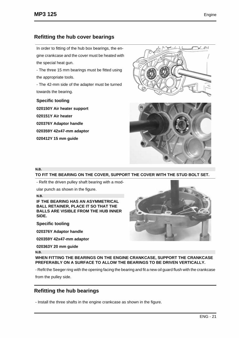
Refitting the hub cover bearings
In order to fitting of the hub box bearings, the en-
gine crankcase and the cover must be heated with
the special heat gun.
- The three 15 mm bearings must be fitted using
the appropriate tools.
- The 42-mm side of the adapter must be turned
towards the bearing.
Specific tooling020150Y Air heater support
020151Y Air heater
020376Y Adaptor handle
020359Y 42x47-mm adaptor
020412Y 15 mm guide
N.B.
TO FIT THE BEARING ON THE COVER, SUPPORT THE COVER WITH THE STUD BOLT SET.
- Refit the driven pulley shaft bearing with a mod-
ular punch as shown in the figure.N.B.
IF THE BEARING HAS AN ASYMMETRICALBALL RETAINER, PLACE IT SO THAT THEBALLS ARE VISIBLE FROM THE HUB INNERSIDE.
Specific tooling020376Y Adaptor handle
020359Y 42x47-mm adaptor
020363Y 20 mm guideN.B.
WHEN FITTING THE BEARINGS ON THE ENGINE CRANKCASE, SUPPORT THE CRANKCASEPREFERABLY ON A SURFACE TO ALLOW THE BEARINGS TO BE DRIVEN VERTICALLY.
- Refit the Seeger ring with the opening facing the bearing and fit a new oil guard flush with the crankcase
from the pulley side.
Refitting the hub bearings
- Install the three shafts in the engine crankcase as shown in the figure.
MP3 125 Engine
ENG - 21

Refitting the ub cover
- Fit a new gasket together with the centring dowels.
- Seal the gasket of the breather pipe using black silicone sealant.
- Fit the gearbox cover, making sure the breather pipe is in the correct position.
- Place the 3 shortest screws, identifiable by their different colour, as shown in the figure.
- Fasten the breather pipe support bracket with the lower short screw.
- Assemble the remaining 4 screws and tighten the 7 screws to the prescribed torque.
Locking torques (N*m)Rear hub cover screws 24 ÷ 27
Engine MP3 125
ENG - 22

Flywheel cover
Removing the hub cover
- Remove the two clamps, the two couplings and
empty the cooling system.
- Remove the 4 retainers and the flywheel cover
Removing the stator
- Remove the electric terminal of the minimum oil
pressure switch.
- Remove the two Pick-Up screws and the one for
the wiring harness bracket as well as the two stator
fixing screws shown in the figure.
- Remove the stator and its wiring.
MP3 125 Engine
ENG - 23
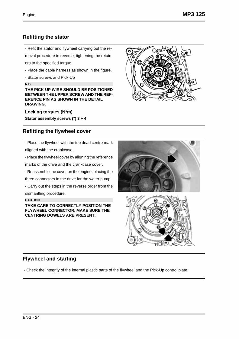
Refitting the stator
- Refit the stator and flywheel carrying out the re-
moval procedure in reverse, tightening the retain-
ers to the specified torque.
- Place the cable harness as shown in the figure.
- Stator screws and Pick-UpN.B.
THE PICK-UP WIRE SHOULD BE POSITIONEDBETWEEN THE UPPER SCREW AND THE REF-ERENCE PIN AS SHOWN IN THE DETAILDRAWING.
Locking torques (N*m)Stator assembly screws (°) 3 ÷ 4
Refitting the flywheel cover
- Place the flywheel with the top dead centre mark
aligned with the crankcase.
- Place the flywheel cover by aligning the reference
marks of the drive and the crankcase cover.
- Reassemble the cover on the engine, placing the
three connectors in the drive for the water pump.
- Carry out the steps in the reverse order from the
dismantling procedure.CAUTION
TAKE CARE TO CORRECTLY POSITION THEFLYWHEEL CONNECTOR. MAKE SURE THECENTRING DOWELS ARE PRESENT.
Flywheel and starting
- Check the integrity of the internal plastic parts of the flywheel and the Pick-Up control plate.
Engine MP3 125
ENG - 24
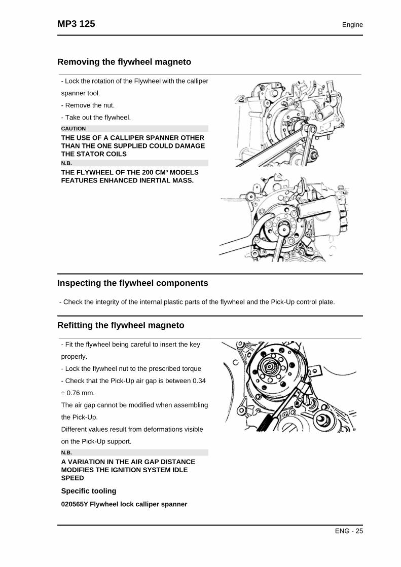
Removing the flywheel magneto
- Lock the rotation of the Flywheel with the calliper
spanner tool.
- Remove the nut.
- Take out the flywheel.CAUTION
THE USE OF A CALLIPER SPANNER OTHERTHAN THE ONE SUPPLIED COULD DAMAGETHE STATOR COILSN.B.
THE FLYWHEEL OF THE 200 CM³ MODELSFEATURES ENHANCED INERTIAL MASS.
Inspecting the flywheel components
- Check the integrity of the internal plastic parts of the flywheel and the Pick-Up control plate.
Refitting the flywheel magneto
- Fit the flywheel being careful to insert the key
properly.
- Lock the flywheel nut to the prescribed torque
- Check that the Pick-Up air gap is between 0.34
÷ 0.76 mm.
The air gap cannot be modified when assembling
the Pick-Up.
Different values result from deformations visible
on the Pick-Up support.N.B.
A VARIATION IN THE AIR GAP DISTANCEMODIFIES THE IGNITION SYSTEM IDLESPEED
Specific tooling020565Y Flywheel lock calliper spanner
MP3 125 Engine
ENG - 25
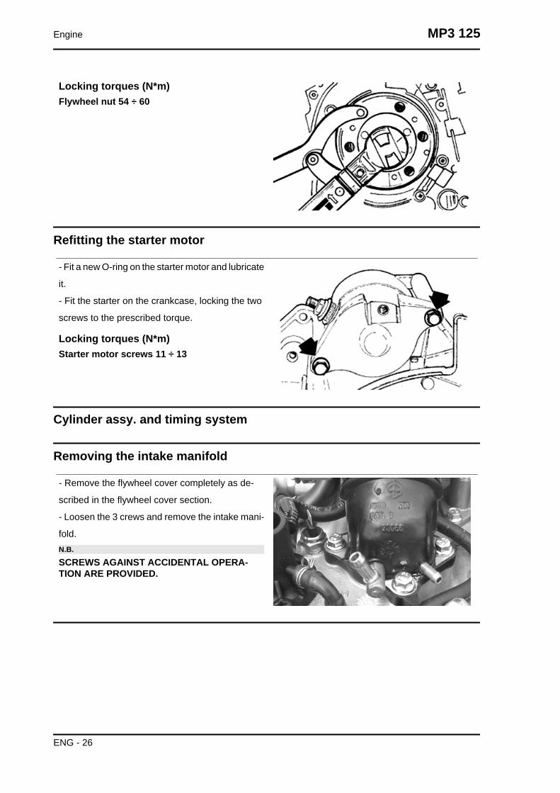
Locking torques (N*m)Flywheel nut 54 ÷ 60
Refitting the starter motor
- Fit a new O-ring on the starter motor and lubricate
it.
- Fit the starter on the crankcase, locking the two
screws to the prescribed torque.
Locking torques (N*m)Starter motor screws 11 ÷ 13
Cylinder assy. and timing system
Removing the intake manifold
- Remove the flywheel cover completely as de-
scribed in the flywheel cover section.
- Loosen the 3 crews and remove the intake mani-
fold.N.B.
SCREWS AGAINST ACCIDENTAL OPERA-TION ARE PROVIDED.
Engine MP3 125
ENG - 26

Removing the rocker-arms cover
- Remove the 5 screws indicated in the figure
Removing the timing system drive
- First remove the parts listed below: transmission
cover, drive pulley with belt, oil sump with spring
and by-pass piston, oil pump pulley cover, O-ring
on the crankshaft and the sprocket wheel separa-
tion washer.
- Remove the tappet cover.
- Remove the central screw fastener and the au-
tomatic valve-lifter retaining cover, as shown in the
figure.
- Remove the return spring of the automatic valve
lifter unit and the automatic valve lifter unit and its
end of stroke washer.
MP3 125 Engine
ENG - 27

- Loosen the central screw on the tensioner first.
- Remove the two fixings shown in the figure.
- Remove the tensioner with its gasket.
- Remove the internal hex screw and the counter-
weight shown in the figure.
- Remove the camshaft control pulley with its
washer.
- Remove the command sprocket wheel and the
timing chain.
- Remove the screws indicated in the figure, the
spacer bar and the tensioner slider.
The chain tensioning pad must be removed from
the transmission side. As regards the lower chain
guide pad, it may only be removed after the head
has been removed.N.B.
IT IS ADVISABLE TO MARK THE CHAIN IN OR-DER TO ENSURE THAT THE INITIAL DIREC-TION OF ROTATION IS MAINTAINED.
Engine MP3 125
ENG - 28
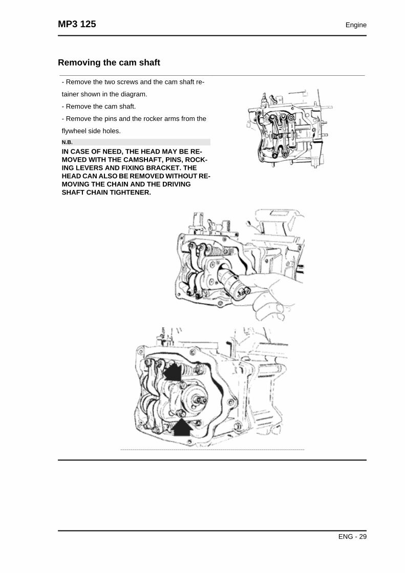
Removing the cam shaft
- Remove the two screws and the cam shaft re-
tainer shown in the diagram.
- Remove the cam shaft.
- Remove the pins and the rocker arms from the
flywheel side holes.N.B.
IN CASE OF NEED, THE HEAD MAY BE RE-MOVED WITH THE CAMSHAFT, PINS, ROCK-ING LEVERS AND FIXING BRACKET. THEHEAD CAN ALSO BE REMOVED WITHOUT RE-MOVING THE CHAIN AND THE DRIVINGSHAFT CHAIN TIGHTENER.
MP3 125 Engine
ENG - 29

Removing the cylinder head
- Remove the spark plug.
- Remove the 2 side fixings shown in the figure.
- Loosen the 4 head-cylinder fastening nuts in two
or three stages and in criss-cross fashion.
- Remove the head, the two centring dowels and
the gasket.N.B.
IN CASE OF NEED, THE HEAD MAY BE RE-MOVED WITH THE CAMSHAFT, PINS, ROCK-ING LEVERS AND FIXING BRACKET. THEHEAD CAN ALSO BE REMOVED WITHOUT RE-MOVING THE CHAIN AND THE DRIVINGSHAFT CHAIN TIGHTENER.
Removing the valves
- Using the appropriate tool fitted with an adapter,
remove the cotter pins, plates, springs and valves.
- Remove the oil guards with the appropriate tool.
- Remove the lower spring supports.CAUTION
REPLACE THE VALVES IN SUCH A WAY ASTO RECOGNISE THEIR ORIGINAL POSITIONON THE HEAD.
Specific tooling020382Y011 adapter for valve removal tool
020382Y Valve cotters equipped with part 012removal tool
020306Y Punch for assembling valve sealrings
Removing the cylinder - piston assy.
- Remove the chain guide pad.
- Pull out the cylinder.
- Remove the cylinder base gasket.
- Remove the two stop rings, the wrist pin and the piston.
- Remove the piston seals.
Engine MP3 125
ENG - 30

CAUTION
TO AVOID DAMAGING THE PISTON, SUPPORT IT WHILE REMOVING THE CYLINDER.N.B.
BE CAREFUL NOT TO DAMAGE THE SEALING RINGS DURING REMOVAL.
MP3 125 Engine
ENG - 31

Inspecting the small end
- Measure the internal diameter of the small end
using an internal micrometer.N.B.
REPLACE THE CRANKSHAFT IF THE DIAME-TER OF THE ROD SMALL END EXCEEDS THESTANDARD DIAMETER OR SHOWS SIGNS OFWEAR OR OVERHEATING.
CharacteristicRod small end check-up: Maximum diameter
15.030 mm
Rod small end check-up: Standard diameter
15 +0.015+0.025 mm
Engine MP3 125
ENG - 32

Inspecting the wrist pin
- Measure the outer diameter of the gudgeon pin.
- Calculate the coupling clearance between pin
and connecting rod end.
- Measure the capacity diameter on the piston.
- Calculate the piston pin coupling clearance.
- Measure the outside diameter of the piston, per-
pendicular to the gudgeon pin axis.
- Carry out the measurement as shown in the fig-
ure.
d: 41.1 mm (from the crown)
- Using a bore meter, measure the inner cylinder
diameter at three different points according to the
directions shown in the figure.
- Check that the head matching surface exhibits no
deformations or wear.
Maximum admissible displacement: 0,05 mm
- Pistons and cylinders are classified into catego-
ries based on their diameter. The coupling is car-
ried out in pairs (A-A, B-B, C-C, D-D).
- The cylinder rectifying operation should be car-
ried out with a surfacing that respects the original
angle.
- The cylinder surface roughness should be 0.9
micron.
- This is indispensable for a good seating of the
sealing rings, which in turn minimises oil consump-
tion and guarantees optimum performance.
- The pistons are oversized due to cylinder rectifi-
cation and are subdivided into three categories
1st, 2nd, 3rd with 0.2-0.4-0.6 mm oversize. They
are also classified into 4 categories A-A, B-B, C-
C, D-D.N.B.
THE PIN HOUSINGS HAVE 2 LUBRICATIONCHANNELS. FOR THIS REASON MEASURE-MENT OF THE DIAMETER MUST BE CARRIEDOUT ACCORDING TO THE AXIS OF THE PIS-TON.
MP3 125 Engine
ENG - 33

CharacteristicPin diameter Standard diameter:
56.997 ÷ 57.025
piston diameter
56.945 ÷ 56.973 mm
Pin diameter: Standard clearance
0.015 ÷ 0.029 mm
Pin diameter Standard diameter
14.996 - 15.000 mm
Wrist pin seat on the piston: Standard diameter
15.001 ÷ 15.006 mm
Diameter of the wrist pin seat on the piston:Standard clearance
0.001 ÷ 0.010 mm
Engine MP3 125
ENG - 34

Inspecting the piston
- Carefully clean the seal housings.
- Measure the coupling clearance between the
seal rings and the grooves using suitable sensors,
as shown in the diagram.
- If the clearance is greater than that indicated in
the table, replace the piston.
Removing the piston
- Install piston and wrist pin onto the connecting rod, aligning the piston arrow the arrow facing towards
the exhaust.
- Fit the pin stop ring onto the appropriate tool.
- With opening in the position indicated on the tool
S = left
D = right
- Place the wrist pin stop ring into position using a punch
- Fit the wrist pin stop using the plug as shown in the figureCAUTIONUSING A HAMMER MIGHT DAMAGE THE STOPS' HOUSING.
MP3 125 Engine
ENG - 35

N.B.
THE TOOL FOR INSTALLING THE STOP RINGS MUST BE USED MANUALLY.
Specific tooling020430Y Pin lock fitting tool
Choosing the gasket
- Provisionally fit the piston into the cylinder, with-
out any base gasket.
- Assemble a dial gauge on the specific tool
Support to check piston position 020428Y
- Set the dial gauge to zero placing the tool on a
contrasting surface. Keeping the zero position, as-
semble the tool on the cylinder and lock it with 2
supplied nuts as shown in the figure.
- Rotate the crankshaft until TDC (the inverted
point of the dial gauge rotation)
- Position the dial gauge on the piston as shown in
the figure and measure how much the piston pro-
trudes.
Engine MP3 125
ENG - 36

- By means of the table shown in the specifications
chapter identify the cylinder base gasket thickness
to be used for refitting. The proper identification of
the cylinder base gasket thickness allows main-
taining the correct compression ratio.
- Remove the specific tool and the cylinder.N.B.
MEASURE PISTON PROTRUSION.
See alsoSlot packing system
Refitting the piston rings
- Place the oil scraper spring on the piston.
- Refit the oil scraper ring with the join of spring
ends on the opposite side from the ring gap and
the word 'TOP' towards the crown of the piston.
The chamfered side of the oil scraper ring should
always be facing the piston crown.
- Fit the middle piston ring with the identification
letter facing the crown of the piston. In any case,
the step must be facing opposite the piston top.
- Fit the top piston ring with the word 'TOP' or the
reference mark facing the crown of the piston.
- Offset the piston ring gaps on the three rings by
120° to each other as shown in the figure.
- Lubricate the components with engine oil.N.B.
THE TWO PISTON RINGS ARE MADE WITH ATAPERED CYLINDRICAL CONTACT CROSS-SECTION. THIS IS TO ACHIEVE A BETTERBEDDING.
MP3 125 Engine
ENG - 37
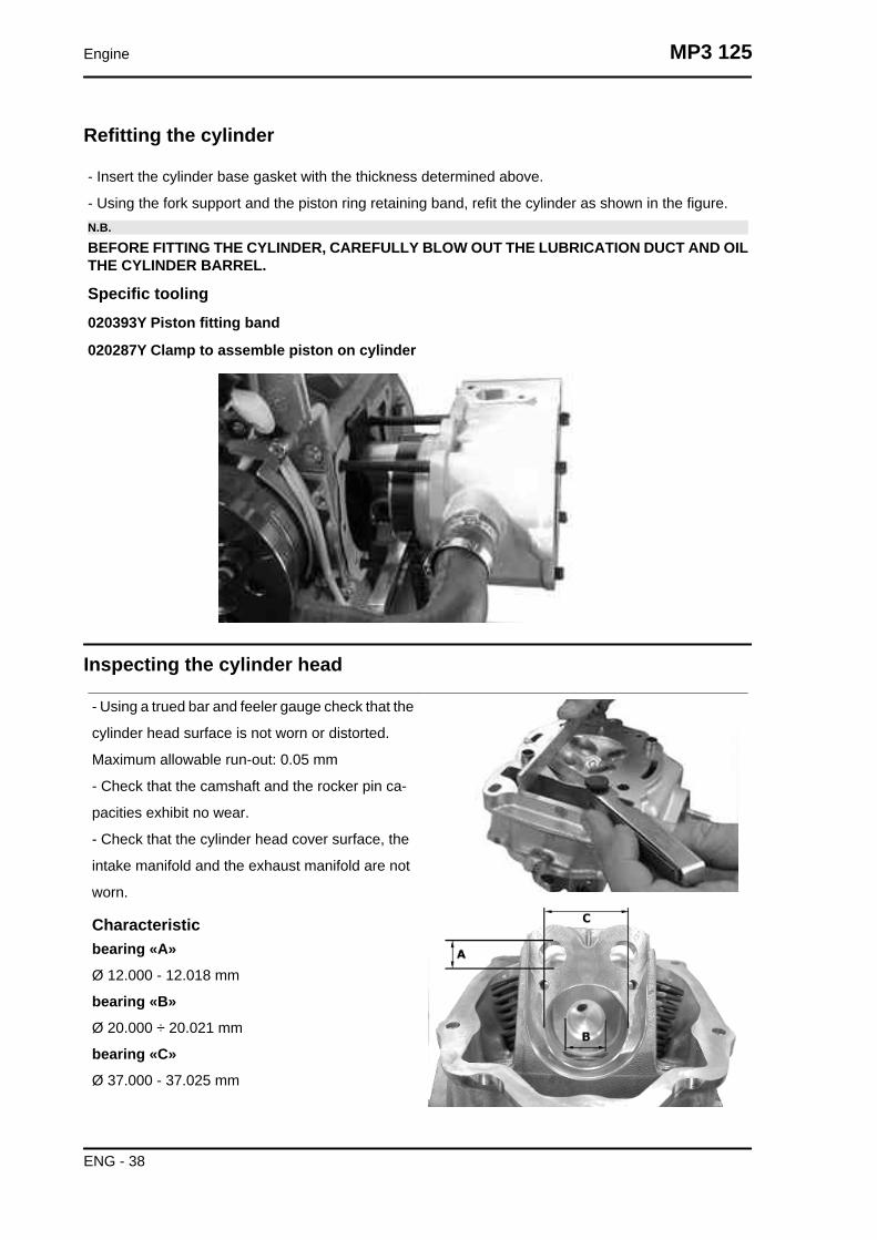
Refitting the cylinder
- Insert the cylinder base gasket with the thickness determined above.
- Using the fork support and the piston ring retaining band, refit the cylinder as shown in the figure.N.B.
BEFORE FITTING THE CYLINDER, CAREFULLY BLOW OUT THE LUBRICATION DUCT AND OILTHE CYLINDER BARREL.
Specific tooling020393Y Piston fitting band
020287Y Clamp to assemble piston on cylinder
Inspecting the cylinder head
- Using a trued bar and feeler gauge check that the
cylinder head surface is not worn or distorted.
Maximum allowable run-out: 0.05 mm
- Check that the camshaft and the rocker pin ca-
pacities exhibit no wear.
- Check that the cylinder head cover surface, the
intake manifold and the exhaust manifold are not
worn.
Characteristicbearing «A»
Ø 12.000 - 12.018 mm
bearing «B»
Ø 20.000 ÷ 20.021 mm
bearing «C»
Ø 37.000 - 37.025 mm
Engine MP3 125
ENG - 38

Inspecting the timing system components
- Check that the guide shoe and the tensioner shoe
are not worn out.
- Ensure that the camshaft control pulley chain as-
sembly and the sprocket wheel are not worn.
- If you encounter wear, replace the parts or, if the
chain, sprocket wheel and pulley are worn replace
the whole assembly.
- Remove the centre screw with the washer and
the tensioner spring. Check that the one-way
mechanism is not worn.
- Check the condition of the tensioner spring.
- If examples of wear are found, replace the whole
assembly.
Inspecting the valve sealings
- Insert the valves into the cylinder head.
- Alternatively check the intake and exhaust
valves.
- The test is carried out by filling the manifold with
petrol and checking that the head does not ooze
through the valves when these are just pressed
with the fingers.
MP3 125 Engine
ENG - 39

Inspecting the valve housings
- Check the width of the imprint on the valve
seat«V» wear limit max. 1.6 mm.
- Remove any carbon formation from the valve
guides.
- Measure the inside diameter of each valve guide.
- Take the measurement at three different heights
in the rocker arm push direction.
- If the width of the impression on the valve seat or
the diameter of the valve guide exceed the speci-
fied limits, replace the cylinder head.
CharacteristicValve seat wear Intake guide
limit accepted: 5.022
Valve seat wear Intake guide
Standard diameter: 5.000 ÷ 5.012 mm
Valve seat wear Exhaust guide
Accepted limit 5.022
Valve seat wear Exhaust guide
Standard diameter: 5.000 ÷ 5.012 mm
Inspecting the valves
- Measure the diameter of the valve stems in the
three positions indicated in the diagram.
- Calculate the clearance between valve and valve
guide.
- Check that there are no signs of wear on the sur-
face of contact with the articulated register termi-
nal.
- If the checks above give no failures, you can use
the same valves. For best sealing results, it is ad-
visable to grind the valves. Grind the valves gently
with a fine-grained lapping compound. During the
grinding, keep the cylinder head with the valve ax-
es in a horizontal position. This will prevent the
lapping compound residues from penetrating be-
tween the valve stem and the guide (see figure).
Engine MP3 125
ENG - 40

CAUTION
TO AVOID SCORING THE FAYING SURFACE,DO NOT KEEP ROTATING THE VALVE WHENNO LAPPING COMPOUND IS LEFT. CAREFUL-LY WASH THE CYLINDER HEAD AND THEVALVES WITH A SUITABLE PRODUCT FORTHE TYPE OF LAPPING COMPOUND BEINGUSED.N.B.
DO NOT CHANGE THE POSITIONS THEVALVES ARE FITTED IN
CharacteristicValve check standard length
Outlet: 94.4 mm
Valve check standard length
Inlet: 94.6 mm
Valve check Maximum admissible clearance
Outlet: 0.072 mm
Valve check Maximum admissible clearance
Inlet: 0.062 mm
Valve check standard clearance
Outlet: 0.025 ÷ 0.052 mm
Valve check standard clearance
Inlet: 0.013 ÷ 0.040 mm
Valve check Minimum admissible diameter
Outlet: 4.95 mm
Valve check Minimum admissible diameter
Inlet: 4.96 mm
Valve check Standard diameter:
Inlet: 4.972 ÷ 4.987 mm
Valve check Standard diameter:
Outlet: 4.96 ÷ 4.975 mm
MP3 125 Engine
ENG - 41
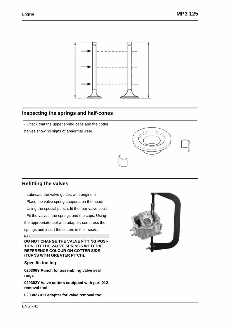
Inspecting the springs and half-cones
- Check that the upper spring caps and the cotter
halves show no signs of abnormal wear.
Refitting the valves
- Lubricate the valve guides with engine oil.
- Place the valve spring supports on the head.
- Using the special punch, fit the four valve seals.
- Fit the valves, the springs and the caps. Using
the appropriate tool with adapter, compress the
springs and insert the cotters in their seats.N.B.
DO NOT CHANGE THE VALVE FITTING POSI-TION. FIT THE VALVE SPRINGS WITH THEREFERENCE COLOUR ON COTTER SIDE(TURNS WITH GREATER PITCH).
Specific tooling020306Y Punch for assembling valve sealrings
020382Y Valve cotters equipped with part 012removal tool
020382Y011 adapter for valve removal tool
Engine MP3 125
ENG - 42
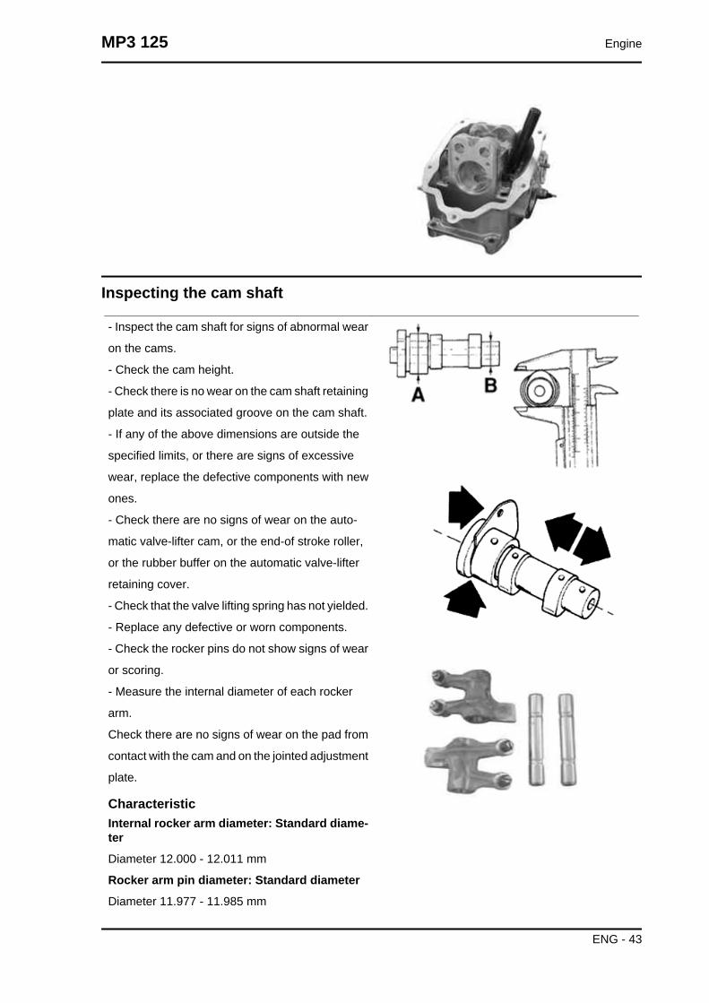
Inspecting the cam shaft
- Inspect the cam shaft for signs of abnormal wear
on the cams.
- Check the cam height.
- Check there is no wear on the cam shaft retaining
plate and its associated groove on the cam shaft.
- If any of the above dimensions are outside the
specified limits, or there are signs of excessive
wear, replace the defective components with new
ones.
- Check there are no signs of wear on the auto-
matic valve-lifter cam, or the end-of stroke roller,
or the rubber buffer on the automatic valve-lifter
retaining cover.
- Check that the valve lifting spring has not yielded.
- Replace any defective or worn components.
- Check the rocker pins do not show signs of wear
or scoring.
- Measure the internal diameter of each rocker
arm.
Check there are no signs of wear on the pad from
contact with the cam and on the jointed adjustment
plate.
CharacteristicInternal rocker arm diameter: Standard diame-ter
Diameter 12.000 - 12.011 mm
Rocker arm pin diameter: Standard diameter
Diameter 11.977 - 11.985 mm
MP3 125 Engine
ENG - 43
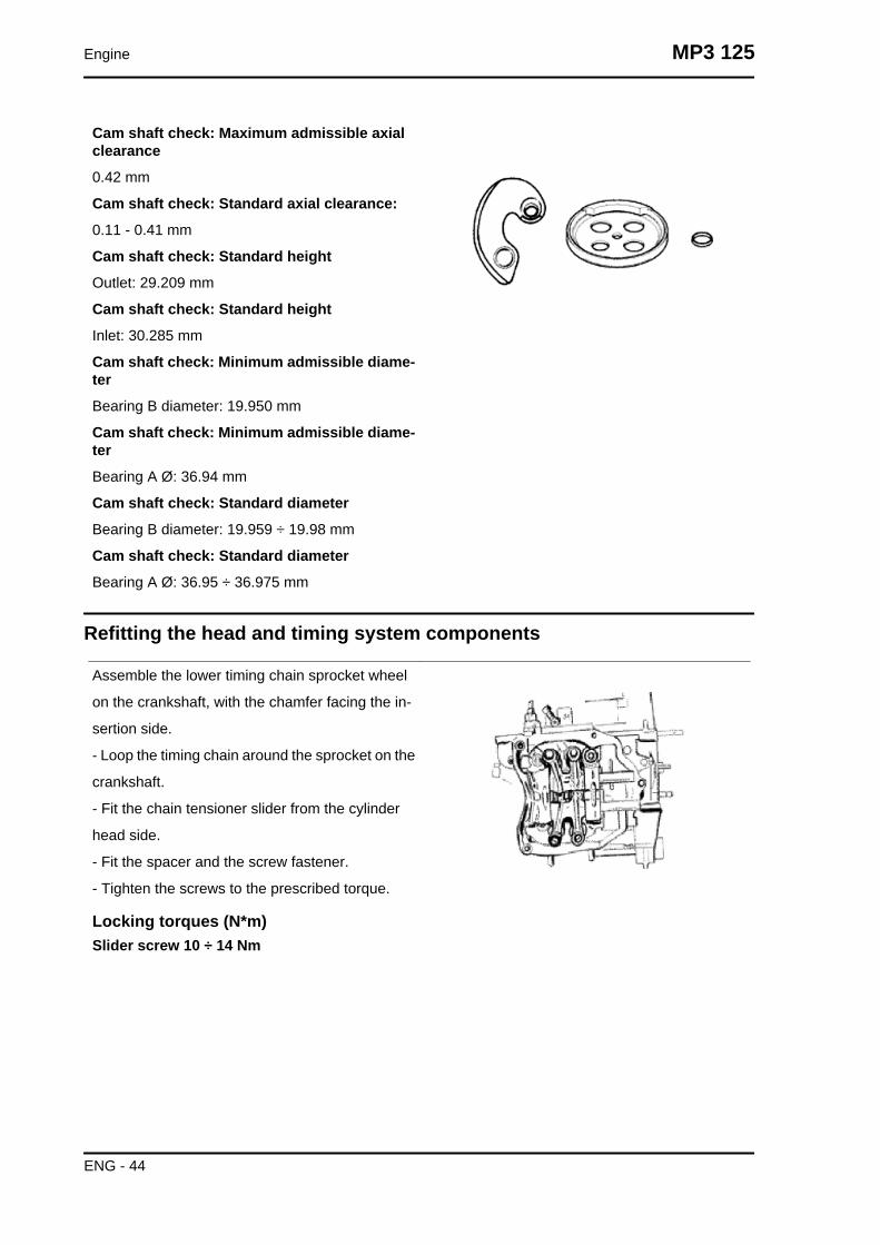
Cam shaft check: Maximum admissible axialclearance
0.42 mm
Cam shaft check: Standard axial clearance:
0.11 - 0.41 mm
Cam shaft check: Standard height
Outlet: 29.209 mm
Cam shaft check: Standard height
Inlet: 30.285 mm
Cam shaft check: Minimum admissible diame-ter
Bearing B diameter: 19.950 mm
Cam shaft check: Minimum admissible diame-ter
Bearing A Ø: 36.94 mm
Cam shaft check: Standard diameter
Bearing B diameter: 19.959 ÷ 19.98 mm
Cam shaft check: Standard diameter
Bearing A Ø: 36.95 ÷ 36.975 mm
Refitting the head and timing system components
Assemble the lower timing chain sprocket wheel
on the crankshaft, with the chamfer facing the in-
sertion side.
- Loop the timing chain around the sprocket on the
crankshaft.
- Fit the chain tensioner slider from the cylinder
head side.
- Fit the spacer and the screw fastener.
- Tighten the screws to the prescribed torque.
Locking torques (N*m)Slider screw 10 ÷ 14 Nm
Engine MP3 125
ENG - 44

Fit the pins and rocking levers.
- Lubricate the two rocking levers through the
holes at the top.
- Lubricate the 2 bearings and insert the cam shaft
in the cylinder head with the cams corresponding
to the rockers.
- Insert the retention plate and tighten the two
screws shown in the figure to the prescribed tor-
que.
Locking torques (N*m)Plate screws 4 ÷ 6 Nm
Insert the spacer on the cam shaft.
- Rotate the engine so that the piston is at top dead
centre, using the reference marks on the flywheel
and the crankcase.
- Holding this position insert the chain on the cam-
shaft control pulley.
- Insert the pulley on the cam shaft while keeping
the reference 4V in correspondence with the ref-
erence mark on the head.
- Assemble the counterweight with the corre-
sponding fixing screw and tighten to the prescribed
torque.
Locking torques (N*m)Counterweight screw 7 ÷ 8.5
Fit the end-of stroke ring on the valve-lifting mass
and fit the automatic valve-lifting cam to the cam-
shaft.N.B.
LUBRICATE WITH GREASE THE END-OF-STROKE RING IN ORDER TO AVOID ACCIDEN-TAL LEAKS THAT MAY FALL INTO THEENGINE. ASSEMBLE THE AUTOMATICVALVE-LIFTER RETURN SPRING. DURINGTHIS OPERATION THE SPRING MUST BE LOA-DED AT APPROXIMATELY 180°.
MP3 125 Engine
ENG - 45

Assemble the limiting bell using the counterweight
fixing screw as a reference.
- Tighten the clamping screw to the prescribed tor-
que.
Locking torques (N*m)Limiting bell screw 11 ÷ 15 Nm
Set the tensioner cursor to the rest position.
- Fit the chain tensioner on the cylinder, using a
new gasket, and tight the two screws to the pre-
scribed torque.
Insert the chain tensioning screw, together with the
spring and washer, tightening it to the prescribed
torque.
Locking torques (N*m)Tensioner screws 11 ÷ 13 Tensioner cover 5 ÷6 Nm
Adjust valve clearance
- Fit the spark plug.
Electrode distance 0.8 mm
Locking torques (N*m)Spark plug 12 ÷ 14
Refit the cylinder head cover, tightening the 5 screws to the prescribed torque. Make sure the gasket
is positioned properly.
Remove the flywheel cover completely as already described in the flywheel chapter.
- Reassemble the oil pump control, the chain compartment cover, the by-pass and the oil sump as
described in the lubrication chapter.
- Reassemble the driving pulley, the belt and the transmission cover as described in the transmission
chapter.
Locking torques (N*m)Tappet cover screws 6 - 7 Nm
TIMING SYSTEM COMPONENTS ASSEMBLYName Torque in Nm
Tappet cover screws 6 - 7 NmSpark plug 12 ÷ 14
Tensioner cover 5 ÷ 6 NmTensioner screws 11 ÷ 13Limiting bell screw 11 ÷ 15 Nm
Engine MP3 125
ENG - 46

Name Torque in NmCounterweight screw 7 ÷ 8.5
Plate screws 4 ÷ 6 NmSlider screw 10 ÷ 14 Nm
- Fit the timing chain guide pad.
- Insert the centring dowel between the cylinder
head to the cylinder, fit the cylinder head gasket
and the cylinder head.
- Lubricate the stud bolt threading.
- Tighten up the nuts to a pre-torque of 7±1 N·m
- Rotate by a 180° angle (2 rotations of 90° each)
- To carry out the operations described above, fol-
low the tightening sequence in the figure.
- Fit the two screws on the outside of the timing
chain side and tighten them to the specified torque.N.B.
BEFORE INSTALLING THE HEAD, MAKESURE THAT THE LUBRICATION CHANNEL ISCLEAN USING A COMPRESSED AIR JET.
Locking torques (N*m)Timing chain tensioner support screw 11 ÷ 13
MP3 125 Engine
ENG - 47
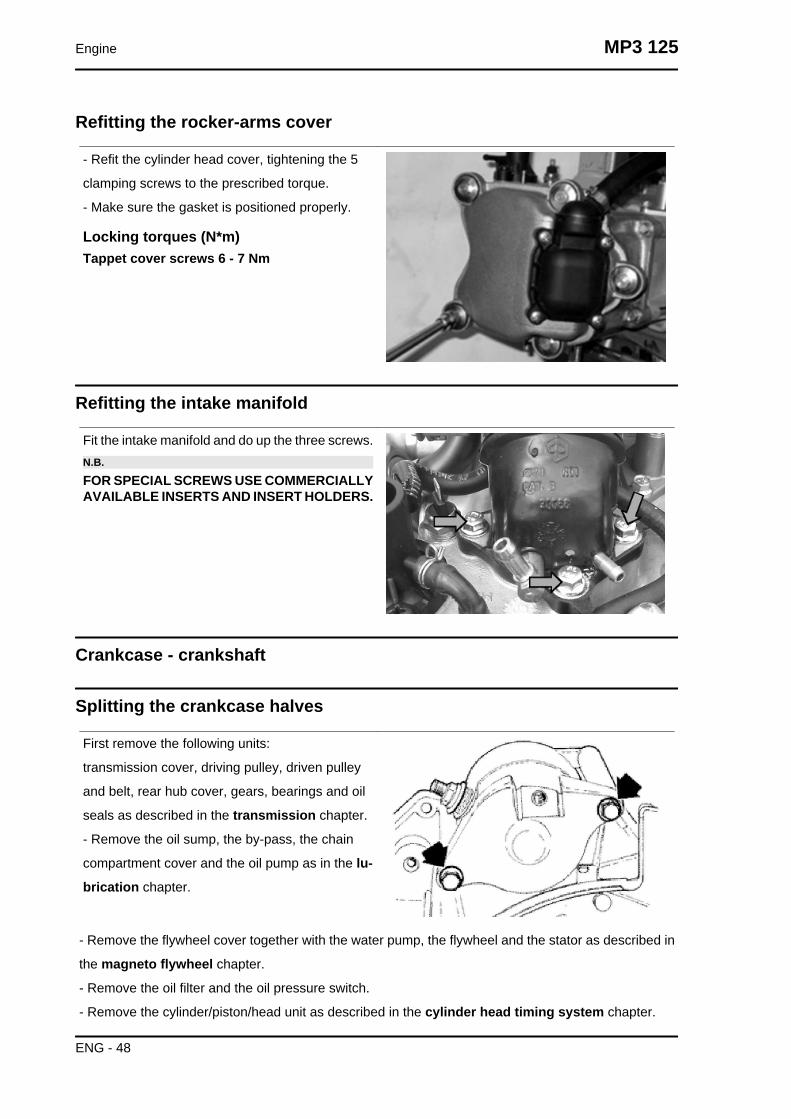
Refitting the rocker-arms cover
- Refit the cylinder head cover, tightening the 5
clamping screws to the prescribed torque.
- Make sure the gasket is positioned properly.
Locking torques (N*m)Tappet cover screws 6 - 7 Nm
Refitting the intake manifold
Fit the intake manifold and do up the three screws.N.B.
FOR SPECIAL SCREWS USE COMMERCIALLYAVAILABLE INSERTS AND INSERT HOLDERS.
Crankcase - crankshaft
Splitting the crankcase halves
First remove the following units:
transmission cover, driving pulley, driven pulley
and belt, rear hub cover, gears, bearings and oil
seals as described in the transmission chapter.
- Remove the oil sump, the by-pass, the chain
compartment cover and the oil pump as in the lu-
brication chapter.
- Remove the flywheel cover together with the water pump, the flywheel and the stator as described in
the magneto flywheel chapter.
- Remove the oil filter and the oil pressure switch.
- Remove the cylinder/piston/head unit as described in the cylinder head timing system chapter.
Engine MP3 125
ENG - 48

- Remove the two retainers indicated in the figure and the starter motor.
Before opening the engine crankcase, it is advis-
able to check axial clearance of the crankshaft. To
do this, use a plate and a support with appropriate
tool dial gauge.
Higher clearances are signs of wear on the sup-
porting surfaces of the crankshaft casing.
Standard clearance: 0.15 ÷ 0.40 mm
Remove the 11 coupling screws to the crankcase.
- Separate the crankcase while keeping the crank-
shaft in one of the two halves of the crankcase.
Remove the crankshaft.CAUTION
KEEP THE CRANKSHAFT IN ONE OF THE TWOHALVES OF THE CRANKCASE WHEN SEPA-RATING IT. IF YOU FAIL TO DO THIS, THECRANKSHAFT MIGHT ACCIDENTALLY FALL.
- Remove the coupling gasket of the crankcase
halves.
- Remove the two screws and the internal cover
shown in the diagram.CAUTION
WHILE OPENING THE CRANKCASES AND RE-MOVING THE DRIVING SHAFT, CHECK THATTHE THREADED SHAFT ENDS DO NOT INTER-FERE WITH THE MAIN BUSHINGS. FAILURETO OBSERVE THIS PRECAUTION CAN DAM-AGE THE MAIN BUSHINGS.
- Remove the oil guard on the flywheel side.
- Remove the oil filter fitting shown in the diagram
MP3 125 Engine
ENG - 49

Fitting clearanceConnecting rod axial clearance 0.20 - 0.50
Check the radial clearance on the connecting rod.
Standard clearance: 0.036 ÷ 0.054 mm
-Check the surfaces that limit the axial free-play
are not scored and measure the width of the crank-
shaft between these surfaces, as shown in the
diagram.
Standard dimensions:
55.75 ÷ 55.90 mmN.B.
WHEN MEASURING THE WIDTH OF THECRANKSHAFT, MAKE SURE THAT THE MEAS-UREMENTS ARE NOT MODIFIED BY THE RAD-IUSES OF FITTINGS WITH THE CRANKSHAFTBEARINGS.
The crankshaft can be reused when the width is
within the standard values and the surfaces show
no signs of scoring.N.B.
IN CASE OF NEW UTILISATION, MAINTAINTHE FIRST FITTING POSITION.
If the axial clearance between crankshaft and crankcase exceeds the standard and the crankshaft does
not have any defect, the problem must be due to either excessive wear or wrong machining on the
engine crankcase.
Engine MP3 125
ENG - 50

Check the diameters of both bearings of the crank-
shaft according to the axes and surfaces shown in
the figure. The half-shafts are classified in two cat-
egories Cat. 1 and Cat. 2 as shown the chart
below.
CharacteristicStandard diameter - Category 2
29.004 ÷ 29.010
Standard diameter - Category 1
28.994 ÷ 29.000
STANDARD DIAMETER
Specification Desc./QuantityStandard diameter - Category 2 29.004 ÷ 29.010Standard diameter - Category 1 28.994 ÷ 29.000
Inspecting the crankshaft alignment
Measure the capacity of both axes X-Y
Specific tooling020074Y Support base for checking crankshaft alignment
CRANKSHAFT ALIGNMENT
Titolo Durata/Valore Testo Breve (< 4000car.)
Indirizzo Immagine
Crankshaft alignment
MP3 125 Engine
ENG - 51

To install the drive shaft on the support and to
measure the misalignment in the 4 points indicated
in figure.
- Check that the driving shaft cone, the tab seat,
the oil seal capacity, the toothed gear and the
threaded tangs are in good working order.
- In case of failures, replace the crankshaft.
The connecting rod head bushings cannot be re-
placed. For the same reason, the connecting rod
may not be replaced and, when cleaning the
crankshaft, be very careful that no impurities get in
through the shaft's lubrication holes.
In order to prevent damaging the connecting rod
bushings, do not attempt cleaning the lubrication
duct with compressed air.
- Make sure that the 2 caps on the crankpin are
properly fitted.
- A wrong installation of a cap can seriously affect
the bushing lubrication pressure.N.B.
THE MAIN BEARINGS ARE NOT GRINDABLE
Specific tooling020074Y Support base for checking crankshaftalignment
CharacteristicOff-line maximum admitted
A = 0.15 mm
B = 0.01 mmC = 0.01 mmD = 0.10 mm
Engine MP3 125
ENG - 52

Inspecting the crankcase halves
- Before proceeding to check the crankcase
halves, thoroughly clean all surfaces and oil ducts.
- On the transmission-side crankcase half, take
particular care when handling the oil pump com-
partment and the oil ducts, the by-pass duct, the
main bushings and the cooling jet on the trans-
mission side (see diagram).
- Take particular care, also, that there are no signs
wear in the oil by-pass valve housing (see Chapter
Lubrication), as this could prevent a good seal in
the valve, which regulates the oil pressure.
- On the flywheel side crankcase half, take partic-
ular care cleaning the oil ducts for the main bush-
ings, the oil duct for the jet that lubricates the
cylinder head and the oil drainage duct at the fly-
wheel side oil seal.
- Inspect the coupling surfaces on the crankcase
halves for scratches or deformation, taking partic-
ular care with the cylinder/crankcase surfaces and
the crankcase halves surfaces.
- Defects in the crankcase coupling gasket be-
tween the crankcase halves or the mating surfaces
shown in the diagram, could cause a drop in the
oil pressure lubricating the main bearings and con-
nection rod.
- Check the main bearing seats that limit axial
clearance in the crankshaft show no signs of wear.
The dimension between these seats is measured
by way of the procedure described previously for
measuring the crankshaft axial clearance and di-
mensions.N.B.THE JET IS FED THROUGH THE MAIN BUSH-INGS. PROPER OPERATION OF THIS COMPO-NENT IMPROVES THE PISTON TOP COOLING.CLOGGING HAS EFFECTS THAT ARE DIFFI-CULT TO DETECT (PISTON TEMPERATUREINCREASE). FAILURE OR LEAK CAN CONSID-
MP3 125 Engine
ENG - 53

ERABLY DECREASE THE MAIN BUSHINGAND CONNECTING ROD LUBRICATION PRES-SURE.N.B.
THE HEAD LUBRICATION CHANNEL IS PRO-VIDED WITH A SHUTTER JET; THIS GIVES A"LOW PRESSURE" HEAD LUBRICATION; THISCHOICE WAS MADE TO REDUCE THE OILTEMPERATURE IN THE SUMP. THE JETCLOGGING IMPAIRS THE HEAD LUBRICA-TION AND THE TIMING MECHANISMS. A JETFAILURE CAUSES A DECREASE OF THE MAINBUSHING AND CONNECTING ROD LUBRICA-TION PRESSURE.
Inspecting the crankshaft plain bearings
- T
o obtain a good bushing lubrication it is necessary
to have both an optimal lubricating pressure (3,2
bar) and a good oil flow rate; the bushings must be
correctly positioned so as not to obstruct the oil
supply channels.
- The main bushings are comprised of two half-
bearings, one with holes and channels for lubrica-
tion whereas the other is solid.
- The solid half-bearing is intended to stand the
thrusts caused by combustion, and for this reason
it is arranged opposite the cylinder.
- To prevent obstructions in the oil feeding chan-
nels, the matching surface of the two half-bearings
must be perfectly perpendicular to the cylinder ax-
is, as shown in the figure.
- The oil feeding channel section is also affected
by the bushings driving depth compared with the
crankshaft axial clearance of the limiting surface.
- Check the inside diameter of the main bushings
in the three directions indicated in the diagram.
- Repeat the measurements for the other bushing
half. see diagram.
- There are three crankcase versions: with RED
main bushings, with BLUE main bushings and with
YELLOW main bushings.
Engine MP3 125
ENG - 54

- There is only one type of main bushing housing
hole in the crankcase
The standard bushing diameter after driving is var-
iable on the basis of a coupling selection.
- The bushing housings in the crankcase are avail-
able in two categories, Cat. 1 and Cat. 2, as are
the crankshafts.
- The main bushings are available in three thick-
ness categories, identified by colour markings, as
shown in the table below.
TYPE IDENTIFICATION
A RED
B BLUE
C YELLOW
Type "A"
- RED
Type "B"
- BLUE
Type "C"
- YEL-
LOW
Crankshaft
half-bearing
1.970 ÷
1.973
1.9703 ÷
1.976
1.976 ÷
1.979
Bush-
ing cat-
egory
Crank-
case
halves
category
Internal bush-
ing diameter
after fitting
Possible
fitting
A 1 29.025 ÷
29.040
Original
B 1 29.019 ÷
29.034
Original
and spare
2 29.028 ÷
29.043
C 2 29.022 ÷
29.037
Original
Match the shaft with two category 1 crank webs
with the category 1 crankcase (or cat. 2 with cat.
2) Furthermore a spare crankcase cannot be
matched with a crankshaft with mixed categories.
The spare crankshaft has half shafts of the same
category.
MP3 125 Engine
ENG - 55

Crankcase
halves
Engine half
shaft
Bushing
Cat. 1 Cat. 1 B
Cat. 2 Cat. 2 B
Cat. 1 Cat. 2 A
Cat. 2 Cat. 1 CN.B.
TO KEEP THIS POSITION OF THE BUSHINGSON THE CRANKCASE, FITTING IS FORCED ONSTEEL RINGS INSERTED IN THE CASTING OFBOTH CRANKCASE HALVES.N.B.
DO NOT TAKE THE MEASUREMENT ON THETWO HALF-SHELL COUPLING SURFACESINCE THE ENDS ARE RELIEVED TO ALLOWBENDING DURING THE DRIVING OPERATION.N.B.
CRANKCASES FOR REPLACEMENTS ARESELECTED WITH CRANKCASE HALVES OFTHE SAME CATEGORY AND ARE FITTEDWITH CATEGORY B BUSHINGS (BLUE)
CharacteristicStandard driving depth
1.35 ÷ 1.6
Diameter of crankcase without bushing
32.953 ÷ 32.963
Refitting the crankcase halves
Studs
Check that the stud bolts have not worked loose
from their seat in the crankcase.
Check the depth of stud bolt driving with a gauge,
as indicated in the photograph. If it varies signifi-
cantly from the driving depth indicated, it means
that the stud bolt has yielded.
In this case, replace it.
Engine MP3 125
ENG - 56

By working on two fitted cylinder head fixing nuts,
nut and lock nut, as shown in the photograph, re-
move the stud bolt from its seat.
Clean the threaded seat on the carter thoroughly.
Refit a new stud bolt and apply the special product
on the threading crankcase side.
Tighten up to the depth of the driving indicated.
Recommended productsLoctite 'Quick Set' Strong 270 threadlock
Strong 270 threadlock
Lubrication
Conceptual diagrams
LUBRICATION CIRCUIT
MP3 125 Engine
ENG - 57

Engine MP3 125
ENG - 58

Oil pressure check
- After removing the flywheel cover as described in the "Flywheel" chapter, remove the electrical con-
nexion of the minimum oil pressure switch and then remove the switch.
- With engine idling at 1650 rpm check that the oil pressure is between 0.5 ÷ 1.2 atm.
- With engine at 6000 rpm check that the oil pressure is between 3.2 ÷ 4.2 atm.
- Remove the appropriate tools once the measurement is complete, refit the oil pressure switch and
washer, tightening it to the specified torque and fit the fan cover.
- If the oil pressure is outside the specified limits, in the following order, check: the oil filter, the oil by-
pass valve, the oil pump and the crankshaft seals.N.B.
THE CHECK MUST BE CARRIED OUT WITH OIL AT THE CORRECT LEVEL AND WITH AN OILFILTER IN GOOD CONDITION.
CharacteristicOil pressure
Minimum pressure admitted at 6000 rpm: 3.2 atm.
Locking torques (N*m)Minimum oil pressure sensor 12 ÷ 14
Crankshaft oil seals
MP3 125 Engine
ENG - 59

Refitting
- Fit the internal bulkhead by locking the two
screws to the prescribed torque.
- Fit the oil filter fitting and tighten it to the specified
torque.
- Place a new gasket on one of the crankcase
halves, preferably on the transmission side, to-
gether with the locating dowels.
- Lubricate the main bushings and insert the crank-
shaft in the transmission side crankcase half.
- Reassemble the two crankcase halves.
For the 200 models reposition the shim washers
as in the original fitting.
- Fit the 11 screws and tighten them to the pre-
scribed torque.
- Lubricate the flywheel oil seal.
- Using the appropriate tool, assemble the oil seal.
- Fit a new O-ring on the pre-filter and lubricate it.
- Insert the filter on the engine with the relative cap.
Tighten to the specified torque.N.B.
FAILURE TO USE THE SPECIFIC TOOL CANRESULT IN AN INCORRECT DEPTH POSITIONAND AS A CONSEQUENCE IN INADEQUATEOIL SEALING.
Specific tooling020425Y Punch for flywheel-side oil seal
Locking torques (N*m)Internal engine crankcase bulkhead (transmis-sion-side half shaft) screws 4 ÷ 6 Oil filter oncrankcase fitting 27 ÷ 33 Engine-crankcasecoupling screws 11 ÷ 13 Engine oil drainageplug/mesh filter 24 ÷ 30
Engine MP3 125
ENG - 60
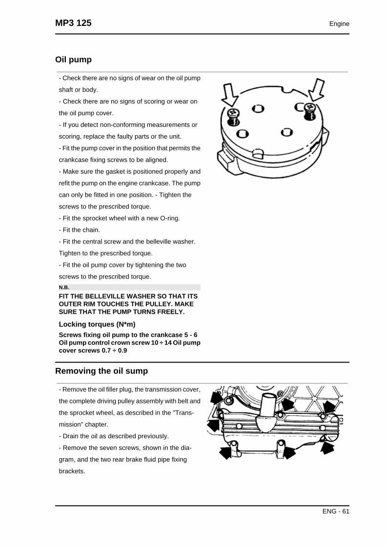
Oil pump
- Check there are no signs of wear on the oil pump
shaft or body.
- Check there are no signs of scoring or wear on
the oil pump cover.
- If you detect non-conforming measurements or
scoring, replace the faulty parts or the unit.
- Fit the pump cover in the position that permits the
crankcase fixing screws to be aligned.
- Make sure the gasket is positioned properly and
refit the pump on the engine crankcase. The pump
can only be fitted in one position. - Tighten the
screws to the prescribed torque.
- Fit the sprocket wheel with a new O-ring.
- Fit the chain.
- Fit the central screw and the belleville washer.
Tighten to the prescribed torque.
- Fit the oil pump cover by tightening the two
screws to the prescribed torque.N.B.
FIT THE BELLEVILLE WASHER SO THAT ITSOUTER RIM TOUCHES THE PULLEY. MAKESURE THAT THE PUMP TURNS FREELY.
Locking torques (N*m)Screws fixing oil pump to the crankcase 5 - 6Oil pump control crown screw 10 ÷ 14 Oil pumpcover screws 0.7 ÷ 0.9
Removing the oil sump
- Remove the oil filler plug, the transmission cover,
the complete driving pulley assembly with belt and
the sprocket wheel, as described in the "Trans-
mission" chapter.
- Drain the oil as described previously.
- Remove the seven screws, shown in the dia-
gram, and the two rear brake fluid pipe fixing
brackets.
MP3 125 Engine
ENG - 61

- Remove the screw, the by-pass piston, the gas-
ket and centring dowels shown in the figure.
Inspecting the by-pass valve
- Check the unloaded spring length.
- Check that the small piston is not scored.
- Ensure that it slides freely on the crankcase and that it guarantees a good seal.
- If not, eliminate any impurities or replace defective parts.
CharacteristicBy-pass check up: Standard length
54.2 mm
Refitting the oil sump
- Refit the by-pass valve plunger in its housing.
- Insert the pressure-regulating spring.
- Fit a new sump seal.
- Refit the two centring dowels.
- Refit the sump, taking care to locate the spring in
the appropriate recess machined into the inside of
the sump.
- Refit the rear brake cable brackets and the
screws in the reverse order from which they were
removed.
- Tighten the screws to the prescribed torque.
Engine MP3 125
ENG - 62
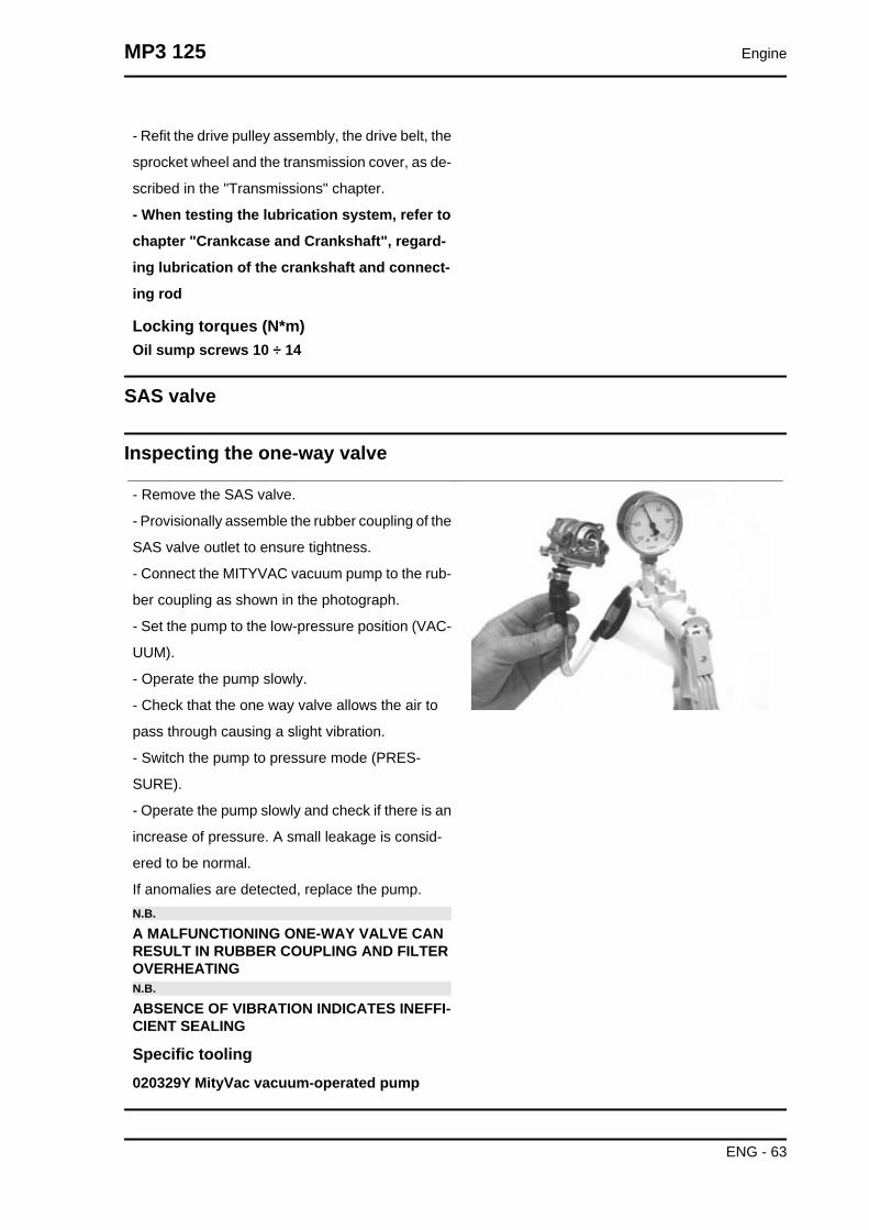
- Refit the drive pulley assembly, the drive belt, the
sprocket wheel and the transmission cover, as de-
scribed in the "Transmissions" chapter.
- When testing the lubrication system, refer to
chapter "Crankcase and Crankshaft", regard-
ing lubrication of the crankshaft and connect-
ing rod
Locking torques (N*m)Oil sump screws 10 ÷ 14
SAS valve
Inspecting the one-way valve
- Remove the SAS valve.
- Provisionally assemble the rubber coupling of the
SAS valve outlet to ensure tightness.
- Connect the MITYVAC vacuum pump to the rub-
ber coupling as shown in the photograph.
- Set the pump to the low-pressure position (VAC-
UUM).
- Operate the pump slowly.
- Check that the one way valve allows the air to
pass through causing a slight vibration.
- Switch the pump to pressure mode (PRES-
SURE).
- Operate the pump slowly and check if there is an
increase of pressure. A small leakage is consid-
ered to be normal.
If anomalies are detected, replace the pump.N.B.
A MALFUNCTIONING ONE-WAY VALVE CANRESULT IN RUBBER COUPLING AND FILTEROVERHEATINGN.B.
ABSENCE OF VIBRATION INDICATES INEFFI-CIENT SEALING
Specific tooling020329Y MityVac vacuum-operated pump
MP3 125 Engine
ENG - 63

Inspecting the cut-off
- Remove the SAS valve
- Connect the MITYVAC pump in depression mode
(VACUUM) to the depression valve socket CUT -
OFF
- Apply a vacuum value higher than 0.5 BAR
- Check that this value is kept at all times
- If a worn seal is detected, replace it.
- With a "T" bypass and flexible rubber hoses make
a parallel connection between the rubber coupling
and the depression uptake of the CUT-OFF valve.
- Connect the bypass to the MITYVAC pump
- Set the pump set to the depression position
(VACUUM)
- Using a pair of long flat pliers, pinch the rubber
hose next to the valve
- Operate the pump until a vacuum higher than 0.5
BAR is created
- Release the hose and check how the vacuum re-
acts
- Under normal functioning the vacuum undergoes
a slight fall and then readjusts. There follows a
slow and continuous loss of depression up to ap-
proximately 0.4 BAR. At this point the valve opens
and the depression is suddenly set to zero.
Lack of tightness or the fact that the valve opens
at different vacuum values should be regarded as
anomalies. In this case, replace it.N.B.
LACK OF TIGHTNESS IN THE CUT-OFF VALVERESULTS IN EXHAUST NOISE (EXPLOSIONSIN THE MUFFLER). INCORRECT CUT-OFFVALVE CALIBRATION CAN RESULT IN CATA-LYTIC CONVERTER MALFUNCTION.N.B.
A FAULTY CUT - OFF VALVE DIAPHRAGM,BESIDES JEOPARDISING THE CORRECT OP-ERATION OF THE CUT-OFF VALVE, ALSODAMAGES IDLE FUNCTIONING.
Specific tooling
Engine MP3 125
ENG - 64

020329Y MityVac vacuum-operated pump
Fuel supply
Removing the carburettor
- To detach the carburettor from the engine, it is
necessary to move the air filter and remove the
throttle control transmission, the automatic starter
connection, the clamps anchoring the carburettor
to the filter housing and to the inlet manifold, the
air delivery pipe to the diaphragm, the heater, the
intake fitting and the TPS cable.
- Remove the heater
- Remove the protection, the bracket and the start-
er acting on the screw shown in the figure.
MP3 125 Engine
ENG - 65

- Remove the 2 screws and the starter support with
the gasket.
- Remove the 4 fixing screws shown in the figure
and the vacuum chamber cover.WARNING
DURING THE REMOVAL OF THE CARBURET-TOR COVER TAKE SPECIAL CARE NOT TORELEASE THE SPRING ACCIDENTALLY.
- Remove the vacuum valve together with the di-
aphragm.
Engine MP3 125
ENG - 66

Remove the tapered pin from the vacuum-operat-
ed valve
- Remove the 4 screws indicated in the figure.
- Remove the chamber with the accelerating
pump, its control and gasket.
- Remove the oil pump seal.
- Remove the intake and outlet valves of the intake
pump from the tankN.B.
CAUTION, THE ACCELERATION PUMPVALVES ARE MADE UP OF NOZZLES, SPRINGAND BALL.N.B.
AVOID REMOVING THE PISTON OF THE PUMPAND ITS CONTROL.
MP3 125 Engine
ENG - 67

Adequately support the carburettor and using a
rod and hammer remove the float pin acting from
the throttle control side.
- Remove the float and the plunger.
- Remove the maximum nozzle
-Remove the maximum nozzle.
Engine MP3 125
ENG - 68

-Remove diffuser.
- Remove the sprayer.N.B.
WHEN CLEANING THE CARBURETTOR BODYREMOVE THE SPRAYER TO AVOID LOSINGPARTS. IF THE SPRAYER IS FORCED IN ITSHOUSING DO NOT ATTEMPT TO REMOVE ITAS THIS WILL ONLY DAMAGE IT.
-Remove the minimum nozzle.
MP3 125 Engine
ENG - 69

- Remove the minimum flow set screw and the
spring.CAUTION
DO NOT ATTEMPT REMOVING PARTS EM-BEDDED IN THE CARBURETTOR BODY SUCHAS: FUEL SUPPLY PIPE, PLUNGER HOUSING,STARTER NOZZLE, PIT COVER FOR PRO-GRESSIONS AND INLET NOZZLE, MINIMUMAND MAXIMUM AIR GAUGE, THROTTLEVALVE CONTROL SHAFT. DO NOT REMOVETHROTTLE-SHAFT CONNECTION SCREWS.THE FIXING SCREWS ARE CAULKED AFTERASSEMBLY AND THEIR REMOVAL DAMAGESTHE SHAFT.
Refitting the carburettor
- Before refitting, wash the carburettor body accu-
rately with petrol and compressed air.
- Pay special attention to the fuel supply pipe and
the plunger seat.
- For maximum circuit, check the air adjustment is
correct as shown in the figure.
Engine MP3 125
ENG - 70

- For the minimum circuit, make sure the following
points are properly cleaned: air gauging, outlet
section controlled by flow screw, progression
holes near the throttle valve.
- For the starter circuit, blow the connection pipe properly with the jet. This is necessary because the
nozzle support hides other inaccessible internal calibrations.
- Blow the intake nozzle properly.N.B.
THE ACCELERATION NOZZLE OUTLET IS EXTREMELY SMALL AND IS ORIENTED TO THETHROTTLE VALVE. NOZZLE INCORRECT ORIENTATION RESULTS IN INADEQUATE SPRAY-ING.
- Check that there are 5 closing ball joints for the operating pipes on the carburettor body.
- Check that the coupling surfaces, the tank and the diaphragm are not dented.
-Check that the depression valve housing pipe is not scratched.
- Check that the throttle valve and the shaft do not show abnormal wear.
- Check that the plunger seat does not show abnormal wear.
- Replace the carburettor in case of irregularities.
- Check that the return spring of the accelerating pump rocking lever is not deformed by over-stretching.N.B.
TO AVOID DAMAGES, DO NOT INTRODUCE METAL OBJECTS IN THE ADJUSTED SECTIONS.
- Wash and blow the minimum nozzle properly and
reassemble it.
MP3 125 Engine
ENG - 71

- Properly wash and blow the components of the
sprayer maximum circuit, the diffuser and the noz-
zle.
- Introduce the sprayer in the carburettor body with
the shortest cylindrical part directed to the diffuser.
- Assemble the diffuser making sure the sprayer is
being adequately inserted and lock it.
-Assemble the maximum nozzle.
- Check that the tapered pin does not show signs
of wear on the sealing surfaces of the shock ab-
sorber pin and the return clamp.
- Replace the rod if worn out.
- Check that the float is not worn on the pin housing or on the contact plate with the plunger and that
there are no fuel infiltration.
- Replace it in case of anomalies.
- Introduce the float with the rod on the fuel feeding tube side.N.B.
INTRODUCE THE RETURN SPRING ON THE FLOAT PLATE ADEQUATELY
Engine MP3 125
ENG - 72

- Remove the drainage screw from the tank, wash
and blow it properly and make sure the accelera-
tion pump pipes are clean.
- Operate the acceleration pump piston repeatedly
and blow with compressed air.
- Reassemble the acceleration pump valves fol-
lowing this order:
INTAKE VALVE (A)
• Spring
• Ball
• Nozzle
IN VALVE (M)
• Ball
• Spring
• NozzleN.B.
THE IN VALVE NOZZLE, CORRESPONDINGTO THE ACCELERATION PUMP, IS MILLED.
-Check the screw tightness introducing a small
amount of fuel in the tank.
- Assemble a new gasket on the tank.
- Assemble the tank on the carburettor body fas-
tening the 4 screws.
- Check that the control roller is free to rotate in its
own seat.N.B.
MAKE SURE THE TANK GASKET IS COR-RECTLY INTRODUCEDN.B.
AVOID DEFORMING THE ACCELERATIONPUMP CONTROL ROCKING LEVER.
- Wash and blow the flow screw properly.
- Check that screw is not deformed and/or rusty.
- Assemble the spring on the screw.
- Screw the flow screw on the carburettor body.
- The screw final position should be determined by an exhaust fume analysis.
MP3 125 Engine
ENG - 73

- Adjust the carburettor by turning the screw twice from the close position.
Level check
- Place the carburettor inclined as shown in the
figure.
- Check that the float reference is parallel to the tank coupling surface
- If different positions are detected, change the plunger control metal plate direction to obtain the position
described above.
Inspecting the valve and needle
- Check that the tapered pin of the vacuum valve
does not show wear.
- Check that the depression valve does not show
threads on the external surfaces.
- Check that the vacuum intake hole is not clogged.
- Check that the diaphragm is not damaged or has
hardened, otherwise replacement the whole valve.
- Insert the tapered pin into the vacuum valve
housing.
- Reassemble the vacuum valve on the carburettor
body taking care that the tapered pin is inserted
into the sprayer.N.B.
THE VALVE CAN BE INSERTED IN ONLY ONEPOSSIBLE POSITION.
Engine MP3 125
ENG - 74

- Reassemble the spring with the pin lock.
- Remove the cover of the vacuum chamber being
careful to correctly insert the spring in its place on
the cover.
- Tighten the screws.
- Wash and blow dry the starter support.
Assemble a new gasket on the carburettor body
and tighten the 2 fixing screws.
Inspecting the automatic choke device
- Check that the automatic starter piston is not de-
formed or rusty.
- Check that the piston slides freely from the seat
to the support.
- Check that the piston sealing gasket is not de-
formed.
- The starter must be more or less functional de-
pending on the ambient temperature.
- Measure the protrusion of the piston as shown in
the figure and check its corresponding value.
- Make sure that the starter is adjusted for the am-
bient temperature.
- The starter should disconnect progressively by
means of electrical heating.
- Check the starter resistance when adjusted to the
ambient temperature.
MP3 125 Engine
ENG - 75

With a 12V battery power the automatic starter and
check that the piston protrudes as much as possi-
ble.
- The correct warm up time depends on the ambi-
ent temperature.
- If protrusion, resistance or timing values are dif-
ferent from the ones prescribed, replace the start-
er.
- Assemble the starter to the carburettor being
careful to position the O-Ring correctly, insert the
plate with the machined side contacting the starter,
tighten the fixing screws.
- Position the starter as shown in the figure.
- Assemble the protection casing.N.B.
TO CARRY OUT THIS CHECK PAY SPECIALATTENTION NOT TO GENERATE SHORT CIR-CUITS USE A CABLE SECTION WITH A TER-MINAL SUITABLE TO BE CONNECTED TO THESTARTER.
CharacteristicCheck the automatic starter: Kehin: Protrusionvalue
10 mm at about 20°C
Check the automatic starter: Keihin maximumtime
5 min
Starter resistance:
20 Ohm
Engine MP3 125
ENG - 76

Adjusting the idle
- The engine does not require frequent idle speed
adjustments, but it is essential to strictly follow cer-
tain rules when adjusting the idle speed.
- Before adjusting the carburettor make sure to re-
spect the lubrication requirements, valve clear-
ance, and complying timing, spark plug should be
in optimum conditions, air filter clean and sealed,
and the exhaust system tight.
- Warm up the engine until the electrical fan is ac-
tivated at least once.
- Using the rpm indicator (020332y), adjust the idle
set screw until reaching 1600 ÷ 1700 rpm.N.B.
THE WASTED SPARK IGNITION SYSTEM OF-FERS REMARKABLE POWER. READINGSMAY NOT BE ACCURATE IF INADEQUATERPM INDICATORS ARE USED. CORRECTCOUPLING OF THE RPM INDICATOR WILL BEINDICATED WHEN IT CAN READ RPM OVER6000 ÷ 8000
After adjusting the idle speed, proceed with the TPS zero setting.
MP3 125 Engine
ENG - 77

Engine MP3 125
ENG - 78

INDEX OF TOPICS
SUSPENSIONS SUSP

This section is devoted to operations that can be carried out on the suspension.
Front
Removing the front wheel
- Remove the 5 fixing screws indicated in the pho-
tograph.
Locking torques (N*m)Wheel fixing screw 20 ÷ 25
Front wheel hub overhaul
- Remove the ball bearing seeger ring indicated in
the photograph
Extract the ball bearing using the specific tool
Specific tooling001467Y014 Pliers to extract ø 15-mm bearings
001467Y017 Bell for bearings, outside Ø 39 mm
Suspensions MP3 125
SUSP - 2

- Remove the oil seal on the roller bearing side
using a screwdriver.
- Remove the roller bearing using the specific tool
Specific tooling020376Y Adaptor handle
020456Y Ø 24 mm adaptor
020363Y 20 mm guide
- Heat the roller bearing seat with a heat gun
- Use the specific tool to introduce and push the
bearing until it stops, with the shielded side facing
out
- Refit the ball bearing locking seeger ring
Specific tooling020151Y Air heater
020376Y Adaptor handle
020359Y 42x47-mm adaptor
020412Y 15 mm guide
- Use the specific tool to fit and push the roller cas-
ing until it stops
- Refit the oil seal on the roller bearing side
- Lubricate the area between the roller bearing and
the ball bearing
Specific tooling020038Y Punch
Recommended productsAGIP GREASE MU3 Grease for odometertransmission gear case
MP3 125 Suspensions
SUSP - 3

Soap-based lithium grease with NLGI 3; ISO-L-
XBCHA3, DIN K3K-20
Handlebar
Removal
• Remove the two handlebar covers as
explained in the Bodywork Chapter.
• Remove the handlebar wiring fixing
clips and disconnect the electric con-
nectors from the brake levers.
• Unscrew the fittings, then remove the
front and rear brake pump piping.
• Remove the flexible transmission of
the accelerator and remove the throt-
tle.
• Loosen the clamp fixing the handlebar
to the steering tube and pulling up-
wards, remove the handlebar, then re-
move the lower plastic cover.N.B.
IF THE HANDLEBAR IS BEING REMOVED TOREMOVE THE STEERING, IT IS ONLY NECES-SARY TO TILT THE HANDLEBAR FORWARDONTO THE FRONT PART OF THE VEHICLEWITHOUT REMOVING THE PARTS FITTED SOAS TO AVOID DAMAGING THE SHAFTS.
Refitting
Carry out the above operations by working in the reverse order from those of the removal.
Locking torques (N*m)Handlebar fixing screw 50 ÷ 55
The tilt mechanism
Suspensions MP3 125
SUSP - 4

Hydraulic system layout
When tilting is locked, the geared motor activates
the hydraulic pump indicated in the photograph
and pressurises the circuit.
The pressurised oil reaches the distribution frame
"T" and the pressure sensor "A". Then, the pipes
branch out to reach the upper joints on the side
steering tubes.
Through the rigid-flexible pipes inside the side
steering tubes, the oil reaches the stem sliding
locking device placed parallel to the shock absorb-
er.
Steering tubes
Remove the brake calliper pipe retainers and the
hydraulic pipe fitting from the brake calliper making
sure there is a container to collect the brake fluid.
MP3 125 Suspensions
SUSP - 5

Disconnect the tone wheel connector indicated in
the photograph.
Remove the hydraulic pipe fitting from the sliding
locking device, making sure again that the liquid
drained is collected.
Remove the upper fittings, on the parallelogram,
of the brake hydraulic pipes and the suspension
lock indicated in the photograph.
Remove the hydraulic pipe fitting fixing nuts indi-
cated in the figure from the support bracket.
Suspensions MP3 125
SUSP - 6

Remove the suspension tilt locking device pipes
from the headstock.
Remove first the flexible part of the calliper from
the steering tube as shown in the photograph, and
then remove the rigid part.
Remove the tone wheel wiring by disconnecting
the connector on the fuel tank after removing the
chassis central cover.
After that, remove the retainers indicated in the
figure.
MP3 125 Suspensions
SUSP - 7

Remove the constant-velocity universal joint from
the steering bar by undoing the nut indicated in the
photograph.
Use a specific tool to remove the upper tightening
ring nut of the steering tube.
Specific tooling020055Y Wrench for steering tube ring nut
Remove the hydraulic pipe support bracket.
Suspensions MP3 125
SUSP - 8

Remove the steering tube lower ring nut and the
protection cap indicated in the photograph.
Now, it is possible to remove the steering tube.
Check that the roller tapered bearing does not
show signs of abnormal wear. If it is, replace it.
MP3 125 Suspensions
SUSP - 9

THE OPERATIONS DESCRIBED BELOW CAN
ALSO BE CARRIED OUT EVEN WHEN THE
SUSPENSION IS FITTED
Remove the lower retainer of the sliding stem
shown in the photograph.
Remove the sliding stem locking device retainers
indicated in the photograph.
Check that the sliding stem locking device does
not show signs of abnormal wear.
Suspensions MP3 125
SUSP - 10
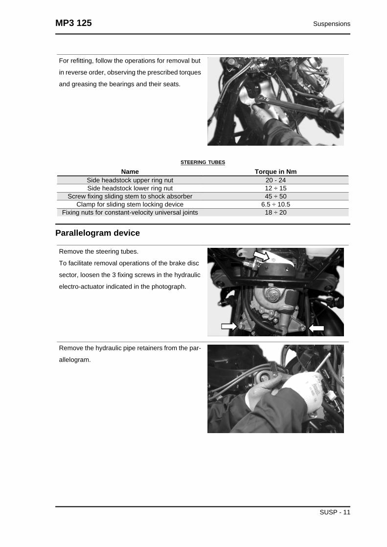
For refitting, follow the operations for removal but
in reverse order, observing the prescribed torques
and greasing the bearings and their seats.
STEERING TUBES
Name Torque in NmSide headstock upper ring nut 20 - 24Side headstock lower ring nut 12 ÷ 15
Screw fixing sliding stem to shock absorber 45 ÷ 50Clamp for sliding stem locking device 6.5 ÷ 10.5
Fixing nuts for constant-velocity universal joints 18 ÷ 20
Parallelogram device
Remove the steering tubes.
To facilitate removal operations of the brake disc
sector, loosen the 3 fixing screws in the hydraulic
electro-actuator indicated in the photograph.
Remove the hydraulic pipe retainers from the par-
allelogram.
MP3 125 Suspensions
SUSP - 11

Remove the 4 screws fixing the tilt brake disc sec-
tor indicated in the photograph.
Remove the retainers indicated in photograph of
the half-arms joint flange.
To facilitate the operations indicated below, re-
move the suspension locking electronic control
unit indicated in the photograph.
Suspensions MP3 125
SUSP - 12
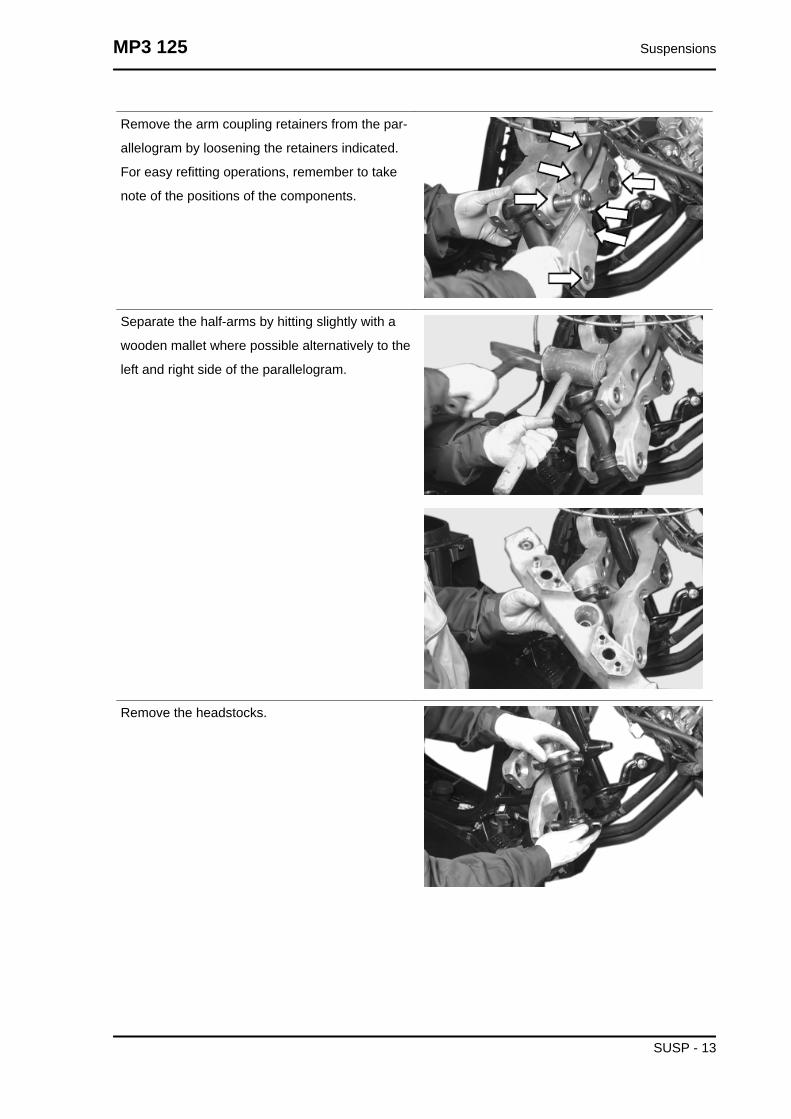
Remove the arm coupling retainers from the par-
allelogram by loosening the retainers indicated.
For easy refitting operations, remember to take
note of the positions of the components.
Separate the half-arms by hitting slightly with a
wooden mallet where possible alternatively to the
left and right side of the parallelogram.
Remove the headstocks.
MP3 125 Suspensions
SUSP - 13

Carry out a visual check of the upper and lower
bearings on the headstocks and their seats. Re-
place them in case of signs of abnormal wear.
Suspensions MP3 125
SUSP - 14

Check the ball bearings on the parallelogram
arms. Replace them in case of signs of abnormal
wear.
Check the inside tracks of the parallelogram bear-
ings on the chassis.
For refitting, follow the operations for removal but
in reverse order, lubricating the locking pins on the
parallelogram half-arms and observing the pre-
scribed torques.
PARALLELOGRAM DEVICE
Name Torque in NmArm coupling screws 45 ÷ 50
Screws fixing arms to side headstocks 45 ÷ 50Screws fixing arms to central headstock 45 ÷ 50
Screws fixing the half-arm coupling flange 20 ÷ 25
MP3 125 Suspensions
SUSP - 15

Name Torque in NmFixing screws for tilt locking disc section 20 ÷ 25
Geared motor and Suspension locking system
Before removing the geared motor:
Disable the suspension lock.
- Remove the front shield.
With the set nut indicated in the photograph, re-
move the tensioning cable of the suspension lock-
ing mechanical calliper.
Remove the electrical connection of the geared
motor position potentiometer.
Remove the electrical connection of the geared
motor electric motor.
Disconnect the hydraulic pipes between the pump
and the sliding stem locking clamps. Empty the
system and use a container to collect the brake
fluid.CAUTION
ELIMINATE ANY REMAINING BRAKE FLUIDSPILLS.
WARNING: BRAKE FLUID IS HIGHLY POISON-OUS. DO NOT INGEST OR SWALLOW. IF AC-
Suspensions MP3 125
SUSP - 16
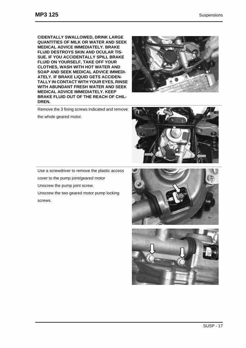
CIDENTALLY SWALLOWED, DRINK LARGEQUANTITIES OF MILK OR WATER AND SEEKMEDICAL ADVICE IMMEDIATELY. BRAKEFLUID DESTROYS SKIN AND OCULAR TIS-SUE. IF YOU ACCIDENTALLY SPILL BRAKEFLUID ON YOURSELF, TAKE OFF YOURCLOTHES, WASH WITH HOT WATER ANDSOAP AND SEEK MEDICAL ADVICE IMMEDI-ATELY. IF BRAKE LIQUID GETS ACCIDEN-TALLY IN CONTACT WITH YOUR EYES, RINSEWITH ABUNDANT FRESH WATER AND SEEKMEDICAL ADVICE IMMEDIATELY. KEEPBRAKE FLUID OUT OF THE REACH OF CHIL-DREN.
Remove the 3 fixing screws indicated and remove
the whole geared motor.
Use a screwdriver to remove the plastic access
cover to the pump joint/geared motor
Unscrew the pump joint screw.
Unscrew the two geared motor pump locking
screws.
MP3 125 Suspensions
SUSP - 17
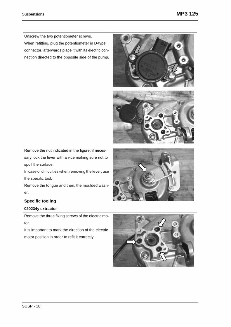
Unscrew the two potentiometer screws.
When refitting, plug the potentiometer in D-type
connector, afterwards place it with its electric con-
nection directed to the opposite side of the pump.
Remove the nut indicated in the figure, if neces-
sary lock the lever with a vice making sure not to
spoil the surface.
In case of difficulties when removing the lever, use
the specific tool.
Remove the tongue and then, the moulded wash-
er.
Specific tooling020234y extractor
Remove the three fixing screws of the electric mo-
tor.
It is important to mark the direction of the electric
motor position in order to refit it correctly.
Suspensions MP3 125
SUSP - 18

Remove the four screws indicated in the figure,
remove the flexible transmission supporting brack-
et, separate the two crankcase halves, if neces-
sary, use a rubber mallet to hit the flexible
transmission lever in order to separate the two
crankcases.
Remove the retaining seeger ring of the bearing of
the flexible transmission lever control shaft bear-
ing.
Remove the bearing with the specific tool.
Specific tooling020376Y Adaptor handle
020441Y 26 x 28 mm adaptor
020362Y 12 mm guide
Extract the electric motor bearing with the specific
tool.
Specific tooling020376Y Adaptor handle
020375Y Adaptor 28 x 30 mm
020363Y 20 mm guide
MP3 125 Suspensions
SUSP - 19

Hold the crankcase in a perfectly horizontal posi-
tion, heat it with a heat gun at a temperature of
about 120 °C, use the specific tool to fit the bearing
of the flexible transmission lever control shaft. Hit
slightly with a mallet if necessary.
Refit the bearing check seeger ring.
Specific tooling020151Y Air heater
020376Y Adaptor handle
020362Y 12 mm guide
020357Y 32 x 35 mm adaptor
Hold the crankcase in a perfectly horizontal posi-
tion, heat it with a heat gun at a temperature of
about 120 °C, use the specific tool to fit the bearing
of the electric motor. Hit slightly with a mallet if
necessary.
Specific tooling020363Y 20 mm guide
020358Y 37x40-mm adaptor
020151Y Air heater
020376Y Adaptor handle
Remove the spring/toothed sector unit from its fit-
ting, slightly hit with a mallet if necessary to release
the unit.
Suspensions MP3 125
SUSP - 20

Extract the bearing of the spring/toothed sector
unit with the specific tool.
Specific tooling001467Y002 Driver for OD 73 mm bearing
Extract the bearing of the electric motor with the
specific tool.
Hold the crankcase in a perfectly horizontal posi-
tion, heat it with a heat gun at a temperature of
about 120 °C, use the specific tool to fit the bearing
of the spring/toothed sector unit. Hit slightly with a
mallet if necessary.
Specific tooling020360Y Adaptor 52 x 55 mm
020151Y Air heater
020376Y Adaptor handle
Hold the crankcase in a perfectly horizontal posi-
tion, heat it with a specific heat gun at a tempera-
ture of about 120 °C, use the specific tool to fit the
bearing of the electric motor. Hit slightly with a
mallet if necessary.
Specific tooling020363Y 20 mm guide
020151Y Air heater
020376Y Adaptor handle
020477Y Adaptor 37 mm
MP3 125 Suspensions
SUSP - 21

Refit the spring/toothed sector unit, hold the crank-
case in a perfectly horizontal and stable position,
place the spring/toothed sector unit keeping it per-
fectly perpendicular to the bearing already fitted on
the crankcase; if necessary, slightly hit the unit
shaft end with a mallet and protect the thread by
screwing in a nut.
Fit the pinion and align the reference on the pinion
teeth with the reference indicated on the second
slot of the toothed sector.
Grease the pinion and the toothed sector with spe-
cific grease.
Refit the toothed sector spacer.
Recommended productsMONTBLANC MOLYBDENUM GREASE MON-TBLANC MOLYBDENUM GREASE
Molybdenum disulphide grease
Lubricate the interference areas, match the crank-
case halves with slight hits of a mallet to get them
into contact.
Place the flexible transmission supporting bracket,
refit the four screws, screw them to the prescribed
torque.
Locking torques (N*m)Geared motor crankcase halves couplingscrews 11 ÷ 13
Suspensions MP3 125
SUSP - 22

Refit the electric motor; check the position is cor-
rect by means of the reference indicated during
removal.
The motor should be so positioned that it does not
protrude from the reduction unit mould, see figure.
Tighten the screws to the prescribed torque.
Locking torques (N*m)Electric motor coupling screws 11 ÷ 13
Place the moulded washer of the flexible trans-
mission control lever shaft and the tongue.
Refit the flexible transmission control lever as
shown in the figure.
Refit the potentiometer (not forcing in the D-type
connector ensures a sole position) with the con-
nector directed to the opposite side of the hydraulic
pump.
Refit the hydraulic pump on the geared motor body
and tighten the screws to the prescribed torque.
Fit but not tighten the pump stem coupling screw
and refit the plastic protection cap.
The synchronisation procedure should be com-
plete when the installation is finished.
Locking torques (N*m)Geared motor hydraulic pump tighteningscrews 11 ÷ 13
MP3 125 Suspensions
SUSP - 23

Remove the two bracket screws after releasing the
spring and freeing the flexible transmission adjust-
ment.
CAUTION: A FIRST PRODUCTION BATCH WILL
BE EQUIPPED WITH DOUBLE COAXIAL
SPRING.
It is very important to remove the flexible trans-
mission from its fitting only for replacement.
When refitting, tighten the two bracket screws and
the flexible transmission lever nut to the prescribed
torque.
Locking torques (N*m)Bracket tightening screws 8 ÷ 12
Unscrew the Allen screw and remove the switch.
When refitting, place the switch with the button ori-
ented to the stop indicated on the calliper lever;
observing the reference indicated on the switch
supporting bracket.
After refitting, check in detail that the switch is reg-
ularly activated by the stop on the lever.
Suspensions MP3 125
SUSP - 24

Unscrew the two pad pin screws, remove the pads
with the spring.
When refitting, tighten the two screws to the pre-
scribed torque and use Threadlock.
When refitting, adjust the cable properly so that the
switch is pushed when the system is unlocked.
MP3 125 Suspensions
SUSP - 25

Select the SYSTEM RESET option from the main
menu
Turn the key switch to ON
Select the LOWER STOP SEARCH option from
the SYSTEM RESET menu
WAIT
PROCEDURE IN PROGRESS
Suspensions MP3 125
SUSP - 26

The hand-held computer indicates the outcome of
the stop search operation:
POSSIBLE LIMIT STOP VALUES. TO EXIT,
PRESS A KEY AND TURN OFF AND ON. SE-
LECT PARAMETERS TO ADJUST AT 12°.
Check the geared motor if the hand-held computer
does not indicate this.
Select the PARAMETERS option from the main
menu
The hand-held computer displays the option: REL-
ATIVE POTENTIOMETER ANGLE
This function is active coming from the LOWER
STOP SEARCH procedure.
NOTE: a slight oscillation of the angle value be-
tween 0.00° and 0.50° is considered normal
Remove the protection cap of the geared motor set
screw
Use a plain slot screwdriver to turn the set screw
anticlockwise until replicating the 12° condition on
the hand-held computer
RELATIVE POTENTIOMETER ANGLE 12° (a
slight value oscillation is considered normal)
Refit the protection cap
MP3 125 Suspensions
SUSP - 27
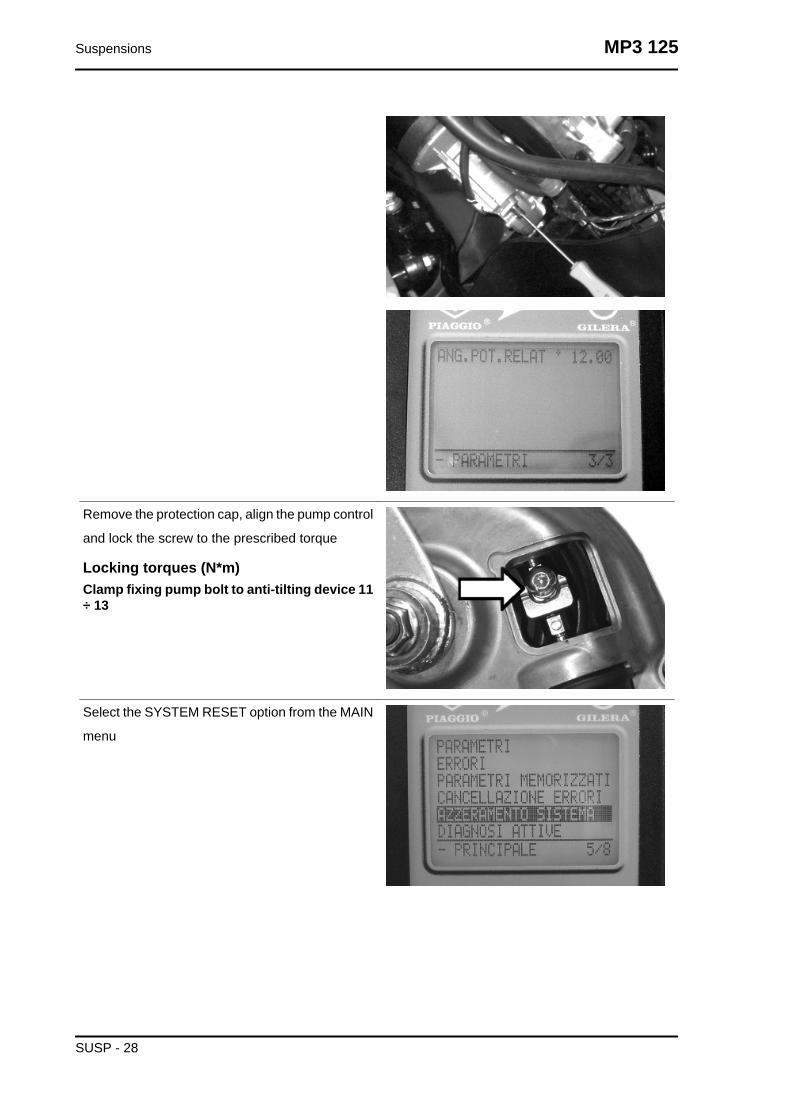
Remove the protection cap, align the pump control
and lock the screw to the prescribed torque
Locking torques (N*m)Clamp fixing pump bolt to anti-tilting device 11÷ 13
Select the SYSTEM RESET option from the MAIN
menu
Suspensions MP3 125
SUSP - 28

Select the POTENTIOMETER RESET option from
the SYSTEM RESET menu and press OK.
WAIT....
PROCEDURE IN PROGRESS
The hand-held computer displays the words:
CHECK THAT THE CONTROL IS SET AT 12°
FROM THE LOWER STOP. PRESS OK TO CON-
TINUE
Press OK
The hand-held computer displays the words: POS-
SIBLE LIMIT STOP VALUES. PRESS A KEY AND
SHIFT OFF AND ON
If this is not successful, the tilt locking mechanism
remains locked for safety.
Adjust the flexible transmission so that a small
clearance is left to guarantee switch activation on
the tilt locking calliper
Electrical devices testPRESSURE SWITCH
MP3 125 Suspensions
SUSP - 29

1: PRESSURE SWITCH
2: HORN REMOTE CONTROL
3: FUSE No. 11, 7.5A
Check 7.5 A fuse No. 11 for efficiency. With inter-
face wiring disconnected from the control unit,
check the continuity of the blue - black cable be-
tween pressure sensor connector and the horn
remote control base as indicated in the photo-
graph. Check the continuity between pin 27 and
the remote control base white cable.
Suspensions MP3 125
SUSP - 30

Check the continuity of the yellow - red cable be-
tween the pressure switch connector and the fuse-
box and between the remote control base and the
fuse-box.
With a multimeter, also check the pressure switch
operation as well as the continuity at rest as this is
normally closed switch.
PRINCIPLE DIAGRAM FOR TILT LOCKING ELECTRICAL SYSTEM
MP3 125 Suspensions
SUSP - 31

1. GEARED MOTOR
2. TILT LOCKING CALLIPER SWITCH
3. TILT UNLOCKING-LOCKING CONTROL SWITCH
4. POTENTIOMETER
5. RIDER PRESENCE SENSOR
6. LEFT SPEED SENSOR
7. RIGHT SPEED SENSOR
8. DIAGNOSTIC TESTER SERIAL LINE
9. ENGINE CONTROL UNIT
10.+ DIRECT BATTERY
11.+ LIVE BATTERY
12.LOW-BEAM LIGHT
13.FUSE No. 3, 20A
14.LOW-BEAM LIGHT REMOTE CONTROL
15.PRESSURE SWITCH
16.HORN REMOTE CONTROL
17.INSTRUMENT PANEL
18.TILT LOCKING SYSTEM CONTROL UNIT
GEARED MOTOR
Suspensions MP3 125
SUSP - 32

1: GEARED MOTOR
With the interface wiring disconnected from the
control unit, check the continuity between pin 28
and the yellow cable, between pin 38 and the blue
cable on the geared motor connector
MP3 125 Suspensions
SUSP - 33

With the interface wiring disconnected from the
control unit, check the continuity of the geared mo-
tor winding placing the multimeter probes on pins
28 and 38 as indicated in the figure
POTENTIOMETER
1: POTENTIOMETER
Suspensions MP3 125
SUSP - 34

With interface wiring connected to the control unit,
secure the vehicle on its centre stand and switch
to "ON". Select the reading scale on 20 V. Insert
the multimeter probes on pins 17 (black) and 25
(red). Check that the voltage in the activated lock-
ing condition is 4V and 1V in the locking rest
condition.
With the interface wiring disconnected from the
control unit, check the continuity between pin 17
and the yellow cable of the potentiometer connec-
tor, between pin 25 and the green-blue cable,
between pin 11 and the orange-blue cable. Also
check that these lines are insulated from each oth-
er and earth.
TILT LOCKING-UNLOCKING SWITCH
MP3 125 Suspensions
SUSP - 35

0: REST POSITION
1: LOCKING POSITION
2: UNLOCKING POSITION
3: TILT LOCKING-UNLOCKING SWITCH
With interface wiring disconnected from the control
unit, check the continuity of the electrical lines be-
tween the interface wiring and the tilt locking-un-
locking switch:
Pin 26 and green - grey cable
Pin 35 and violet - black cable
Pin 33 and yellow - blue cable
Also check that the above indicated electrical lines
are insulated from the earth.
Suspensions MP3 125
SUSP - 36
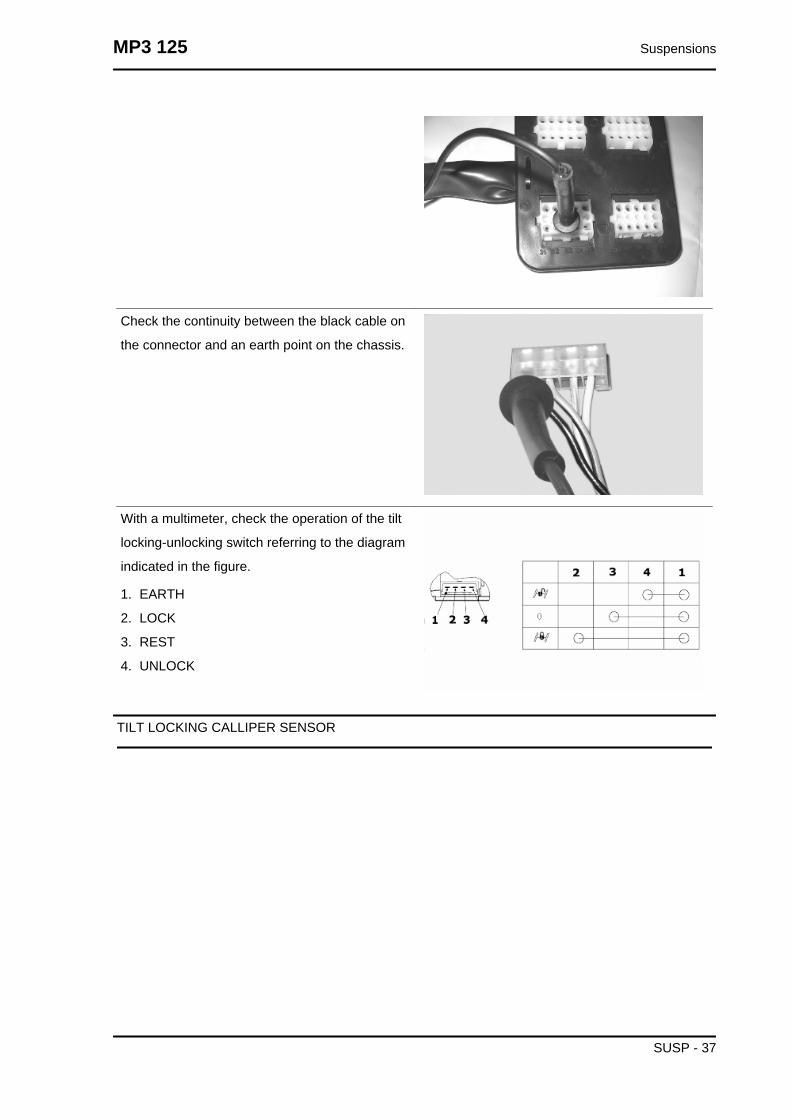
Check the continuity between the black cable on
the connector and an earth point on the chassis.
With a multimeter, check the operation of the tilt
locking-unlocking switch referring to the diagram
indicated in the figure.
1. EARTH
2. LOCK
3. REST
4. UNLOCK
TILT LOCKING CALLIPER SENSOR
MP3 125 Suspensions
SUSP - 37

1: TILT LOCKING CALLIPER SENSOR
The tilt locking calliper sensor is a normally opened
switch. Check its correct operation with a multi-
meter.
Suspensions MP3 125
SUSP - 38

With interface wiring disconnected from the control
unit, check the continuity between pin 34 and the
brown cable of the tilt locking gripper sensor con-
nector on the system side.
Check the continuity of the connector black cable
and an earth point on the chassis
Also check that the flexible transmission control
lever activates the limit stop switch properly.
TONE WHEEL SENSOR
1: Right tone wheel
2: Left tone wheel
MP3 125 Suspensions
SUSP - 39

With interface wiring disconnected from the park-
ing electrical control unit and connected to the
system, check that the sensor resistance between
pins 23 - 17 and 24 - 17 is between 774 and 946
Ohm at a temperature of approximately 20°
With interface wiring disconnected from the control
unit, check the continuity between pin 23 and the
brown cable of the LEFT wheel revolution sensor
connector; between pin 17 and the red cables of
the LEFT wheel revolution sensor and brown cable
of the RIGHT sensor; between pin 24 and the red
cable of the RIGHT wheel revolution sensor
In case of failures, check the continuity between
pin 23 and the connector green cable on the fuel
tank after removing the chassis central cover; be-
tween pin 17 and the yellow cables on both con-
nectors; between pin 24 and the red cable on the
connector.
With interface wiring disconnected from the control unit and the connectors disconnected from wheel
turning sensors, check that pin 23 - 17 and 24 - 17 are insulated from each other and from earth.
Suspensions MP3 125
SUSP - 40

With a thickness gauge, check that the air gap be-
tween the screw head and the sensor is between
0.35 and 1 mm
RIDER PRESENCE SENSOR
MP3 125 Suspensions
SUSP - 41

1: RIDER PRESENCE SENSOR
With interface wiring disconnected from the control
unit and connected to the system, check the fol-
lowing conditions:
pin 17 - 36: resistance 15 ÷ 18 kOhm when the
rider is not seated on the saddle.
pin 17 - 36: resistance of about 3 kOhm when the
rider is seated on the saddle
Suspensions MP3 125
SUSP - 42

Check the continuity between the interface wiring
pin 17 and the yellow cable of the rider presence
connector.
Check the continuity between the interface wiring
pin 36 and violet cable of the rider presence con-
nector.
Wheel alignment
Tool fitting
Metodo di utilizzo dell'attrezzatura
• Verificare che la pressione pneumatici
sia corretta.
• Posizionare il veicolo su un pavimento
piano privo di asperità e irregolarità .
• Posizionare il veicolo sul cavalletto
centrale.
• Assicurarsi che il sistema di staziona-
mento sia sbloccato.
• Sollevare le ruote anteriori come mos-
trato in foto
• Verificare la regolarità di rotazione dei
cerchi ruota e l'eventuale presenza di
giochi anomali dei cuscinetti e delle so-
spensioni.
• Verificare che il comando dello sterzo
non presenti giochi anomali su giunti e
cuscinetti. In caso contrario procedere
MP3 125 Suspensions
SUSP - 43
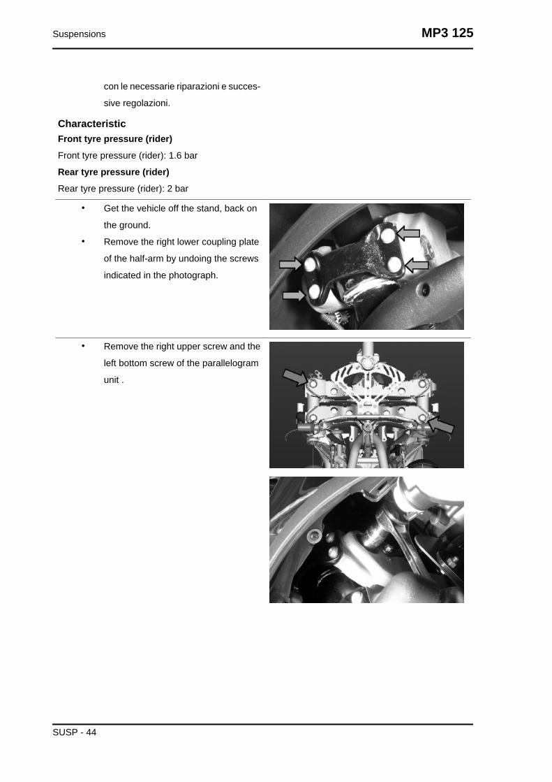
con le necessarie riparazioni e succes-
sive regolazioni.
CharacteristicFront tyre pressure (rider)
Front tyre pressure (rider): 1.6 bar
Rear tyre pressure (rider)
Rear tyre pressure (rider): 2 bar
• Get the vehicle off the stand, back on
the ground.
• Remove the right lower coupling plate
of the half-arm by undoing the screws
indicated in the photograph.
• Remove the right upper screw and the
left bottom screw of the parallelogram
unit .
Suspensions MP3 125
SUSP - 44

• Fit the bracket locking the parallelo-
gram in the holes of the previously re-
moved screws; use the screws sup-
plied with the tool and be careful to
correctly centre the spacer in the bear-
ing.
• Remove the nut fixing the steering con-
trol arm and keep the original washer
in position.
• Fit the steering guiding bracket in a
straight riding position, fix one end to
the attachment of the half-arm coupling
flange and the other end to the screw
fixing the steering control arm.
MP3 125 Suspensions
SUSP - 45

• Place the frame so that the sliders
come into contact with the rim maxi-
mum diameter but without interfering
with the tyre. If required, reposition the
frame by operating the 3 adjustable
support feet.
• Fit the frame locking bracket
• Make sure the frame is adequately
centred by checking with a gauge that
the lugs along the vertical axis show
the standard protrusion.
Suspensions MP3 125
SUSP - 46

• Check that the pointers of both tyres
are correctly aligned, as shown in the
photograph. Maximum misalignment
allowed: 4 notches
Rear
Removing the rear wheel
Remove the full muffler assembly.
- Remove the screw fixing the right-hand shock
absorber to the bracket
- Remove the two screws supporting the brake
calliper on the bracket
MP3 125 Suspensions
SUSP - 47

- Remove the cotter pin, the cap, the wheel axle
fixing nut and the outer one of the two spacers.
- Remove the mud guard clamping screw
- Remove the two screws fixing the bracket to the
engine
- Undo the wheel axle bracket, using the heat gun if necessary.
Refitting the rear wheel
To fit, follow the removal steps but in the reverse
sequence, being careful to fit the spacers on the
wheel axle as shown in the photograph.
Locking torques (N*m)Muffler arm clamping screws 27 ÷ 30 Rearwheel axle nut 104 ÷ 126 Shock absorber-crankcase attachment bracket 20 ÷ 25 Lowershock absorber clamping screw 33 ÷ 41 NmRear brake calliper fixing screws 25 ÷ 30 Nm
Swing-arm
Suspensions MP3 125
SUSP - 48

Removal
- Place the scooter on its centre stand;
- Remove the swinging arm/engine fitting shown in
the photo
- Move the engine back
- remove the spring anchoring the swinging arm to
the frame as shown in the photo
- Remove the two screws fixing the buffer support
bracket to the frame
- Undo the nut on the LHS shown in the figure and
remove the corresponding bolt from the opposite
side.
- Remove the swinging arm.
MP3 125 Suspensions
SUSP - 49
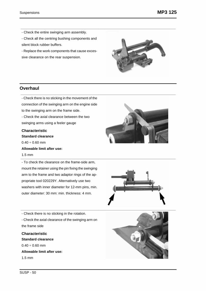
- Check the entire swinging arm assembly.
- Check all the centring bushing components and
silent block rubber buffers.
- Replace the work components that cause exces-
sive clearance on the rear suspension.
Overhaul
- Check there is no sticking in the movement of the
connection of the swinging arm on the engine side
to the swinging arm on the frame side.
- Check the axial clearance between the two
swinging arms using a feeler gauge
CharacteristicStandard clearance
0.40 ÷ 0.60 mm
Allowable limit after use:
1.5 mm
- To check the clearance on the frame-side arm,
mount the retainer using the pin fixing the swinging
arm to the frame and two adaptor rings of the ap-
propriate tool 020229Y. Alternatively use two
washers with inner diameter for 12-mm pins, min.
outer diameter: 30 mm: min. thickness: 4 mm.
- Check there is no sticking in the rotation.
- Check the axial clearance of the swinging arm on
the frame side
CharacteristicStandard clearance
0.40 ÷ 0.60 mm
Allowable limit after use:
1.5 mm
Suspensions MP3 125
SUSP - 50
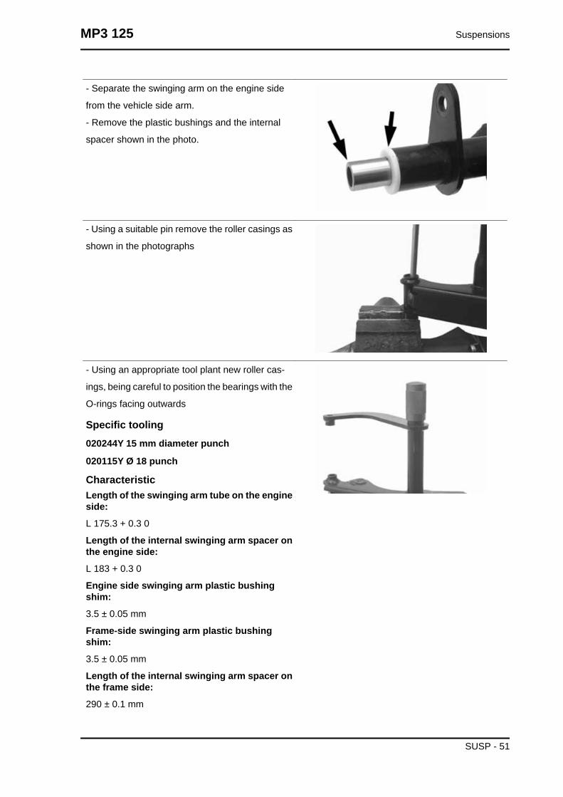
- Separate the swinging arm on the engine side
from the vehicle side arm.
- Remove the plastic bushings and the internal
spacer shown in the photo.
- Using a suitable pin remove the roller casings as
shown in the photographs
- Using an appropriate tool plant new roller cas-
ings, being careful to position the bearings with the
O-rings facing outwards
Specific tooling020244Y 15 mm diameter punch
020115Y Ø 18 punch
CharacteristicLength of the swinging arm tube on the engineside:
L 175.3 + 0.3 0
Length of the internal swinging arm spacer onthe engine side:
L 183 + 0.3 0
Engine side swinging arm plastic bushingshim:
3.5 ± 0.05 mm
Frame-side swinging arm plastic bushingshim:
3.5 ± 0.05 mm
Length of the internal swinging arm spacer onthe frame side:
290 ± 0.1 mm
MP3 125 Suspensions
SUSP - 51

Length of the swinging arm tube on the frameside:
283 ± 0.1 mm
- Lubricate roller casings and the plastic bushings
with grease
- Insert the spacers
- Assemble the two arms with the relative bolt in
the position shown in the photograph
- Adjust the bolt as shown in the photograph
- Position the frame side swinging arm with the
most protruding part pointing towards the silent
block side as shown in the photograph
Recommended productsAGIP GREASE PV2 Grease for the steeringbearings, pin seats and swinging arm
Soap-based lithium and zinc oxide grease con-
taining NLGI 2; ISO-L-XBCIB2 of the swinging arm
- Make sure the silent bloc is not broken. If there
is, replace it.
- Remove the seeger ring shown in the photograph
- Remove the full silent bloc bracket
- Undo the silent bloc ring shown in the photograph
Suspensions MP3 125
SUSP - 52

- Hold the full silent bloc bracket in the clamp
- Using the appropriate tool, remove the silent bloc
from the bracket from the side corresponding to
the inside of the vehicle. This is to guarantee the
tool is centred properly on the support
- Install a new silent bloc, making sure it aligns
properly with the reference tooth.
- Fit the silent blocs, making sure the chamfered
part of the silent bloc matches the chamfered part
of the bracket
- Using the appropriate tool, fit the silent bloc as
shown in the photo
Refitting
- To refit, perform the removal operations in reverse.
- Grease the bearings and the rolling parts with the recommended grease.
MP3 125 Suspensions
SUSP - 53

-Complete the fitting by tightening the nuts on the relative bolts to the proper tightening torque.
Locking torques (N*m)Engine-swinging arm bolt 55 ÷ 61 Frame-swinging arm bolt 55 ÷ 61 Swinging arm buffer nut 64- 72 Engine arm bolt - frame arm 33 ÷ 41
Shock absorbers
Removal
Proceed as follows:
- place the scooter on its centre stand;
- lift the engine a little with a jack so as to free the
two shock absorbers;
- remove the muffler
- undo the shock absorber spring assembly clamp-
ing screw from the support fixed to the engine on
the one side and from that fixed to the muffler on
the other;
- unscrew the two upper nuts (one on each side)
fixing the shock absorber spring assembly to the
frame and remove the shock absorbers.
Refitting
Carry out the previous operations but in reverse order.
Locking torques (N*m)Shock absorber lower clamp 33 ÷ 41 Upper shock absorber clamp 33 ÷ 41
Suspensions MP3 125
SUSP - 54
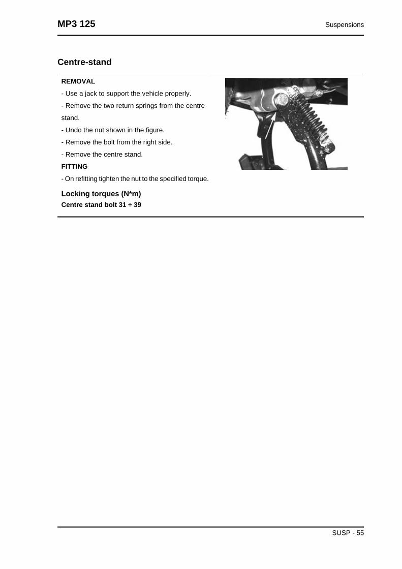
Centre-stand
REMOVAL
- Use a jack to support the vehicle properly.
- Remove the two return springs from the centre
stand.
- Undo the nut shown in the figure.
- Remove the bolt from the right side.
- Remove the centre stand.
FITTING
- On refitting tighten the nut to the specified torque.
Locking torques (N*m)Centre stand bolt 31 ÷ 39
MP3 125 Suspensions
SUSP - 55

Suspensions MP3 125
SUSP - 56

INDEX OF TOPICS
BRAKING SYSTEM BRAK SYS

This section è is devoted to the description of the braking system components.
Rear brake calliper
Removal
- Remove the muffler.
- Remove the two rear brake calliper devices fas-
tening them to the support as shown in the photo-
graph.N.B.
IF IT IS NECESSARY TO REPLACE OR SERV-ICE THE BRAKE CALLIPER, BEFORE REMOV-ING THE FITTINGS FIXING THE CALLIPER TOTHE SUPPORT BRACKET, FIRST LOOSENTHE OIL HOSE FITTING AFTER HAVING EMP-TIED THE SYSTEM OF THE CIRCUIT BEINGEXAMINED.
Removal
Place a container under the calliper, unscrew the
tube-calliper joint and empty the braking system.
For easy draining of the braking system fluid, open
the pump reservoir cap.
Loosen the two screws indicated in the figure and
remove the calliper from the support.
When refitting, tighten the two calliper retainers to
the prescribed torque.
Locking torques (N*m)Screw tightening calliper to the support 24 ÷ 27
Braking system MP3 125
BRAK SYS - 2

Removal
Remove the split pin.
Use new split pins when refitting.
Undo the wheel hub nut.
- When refitting, secure to the specified torque.
Locking torques (N*m)Wheel axle nut 74 ÷ 88
Remove the seeger ring, after that, remove the
hub with the help of a rubber mallet slightly hitting
on the brake disc side, turning the wheel hub at the
same time.
Loosen the 6 screws indicated in the figure and
remove the brake disc from the wheel hub.
- When refitting, secure to the specified torque.
Recommended productsLoctite 242 product description
Apply LOCTITE medium type 242 threadlock
MP3 125 Braking system
BRAK SYS - 3

Removal
Rest the vehicle on its centre stand and use the
corresponding jack to lift the two front wheels; un-
screw the five Allen screws indicated in the figure
Remove the pad upper closing cap.
Remove the pad pin lock with a screwdriver, pay-
ing attention not to spoil the calliper surface treat-
ment.
Use a corresponding measuring punch to extract
the pad pin, if necessary move the brake pipes
manually to release the pin.
Then, remove the spring and the pads.
Fit a new pad kit following the procedure but in re-
verse order.
Locking torques (N*m)Wheel fixing screw 20 ÷ 25
Front brake pump
Brake pipesFront brake pipes removal
Braking system MP3 125
BRAK SYS - 4
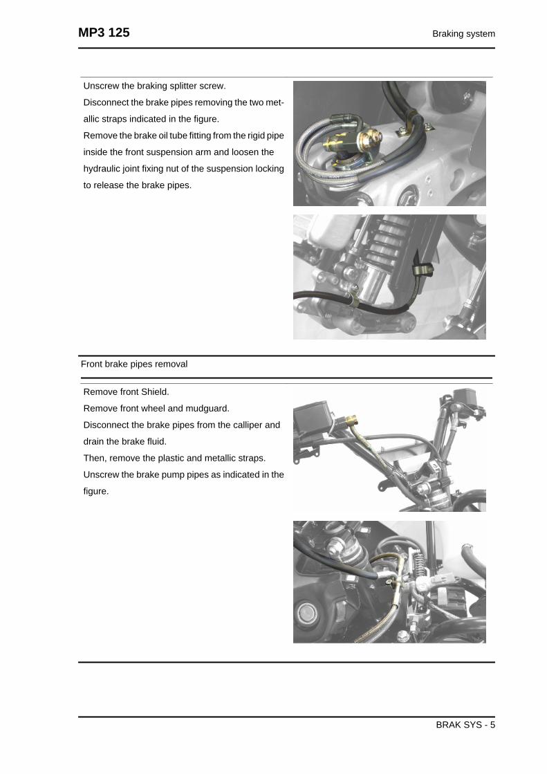
Unscrew the braking splitter screw.
Disconnect the brake pipes removing the two met-
allic straps indicated in the figure.
Remove the brake oil tube fitting from the rigid pipe
inside the front suspension arm and loosen the
hydraulic joint fixing nut of the suspension locking
to release the brake pipes.
Front brake pipes removal
Remove front Shield.
Remove front wheel and mudguard.
Disconnect the brake pipes from the calliper and
drain the brake fluid.
Then, remove the plastic and metallic straps.
Unscrew the brake pump pipes as indicated in the
figure.
MP3 125 Braking system
BRAK SYS - 5

Parking brake
Remove the muffler loosening the 3 screws and
the strap on the drainage tube indicated in the
photograph.
When refitting, place the parking brake flexible
transmission retaining strap correctly.
Loosen the transmission set screw and release the
cable from the calliper.
Remove the two fixing screws of the mechanic
calliper and remove the calliper. To check calliper
components, refer to the chapter on the tilt locking
calliper.
When refitting, secure to the specified torque.
Locking torques (N*m)Screw tightening calliper to the support 20 ÷ 25
After removing the shield back plate, remove the
engaging cable for the safety mechanism remov-
ing it from its fitting.
Remove the 4 screws shown in the figure.
When refitting, pay attention to insert the metallic
cable peg in the fitting marked «A» as indicated in
the enlarged photograph.
Braking system MP3 125
BRAK SYS - 6

Remove the electric connection from the engaged
parking brake warning light switch.
Remove the parking brake cable from the lever by
operating the set screw indicated in the photo-
graph.
MP3 125 Braking system
BRAK SYS - 7

Braking system MP3 125
BRAK SYS - 8

INDEX OF TOPICS
COOLING SYSTEM COOL SYS
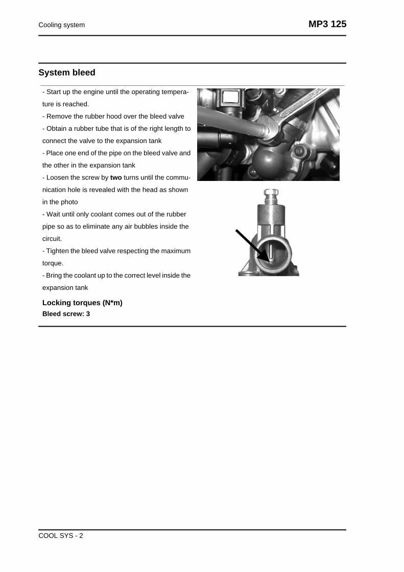
System bleed
- Start up the engine until the operating tempera-
ture is reached.
- Remove the rubber hood over the bleed valve
- Obtain a rubber tube that is of the right length to
connect the valve to the expansion tank
- Place one end of the pipe on the bleed valve and
the other in the expansion tank
- Loosen the screw by two turns until the commu-
nication hole is revealed with the head as shown
in the photo
- Wait until only coolant comes out of the rubber
pipe so as to eliminate any air bubbles inside the
circuit.
- Tighten the bleed valve respecting the maximum
torque.
- Bring the coolant up to the correct level inside the
expansion tank
Locking torques (N*m)Bleed screw: 3
Cooling system MP3 125
COOL SYS - 2

INDEX OF TOPICS
CHASSIS CHAS
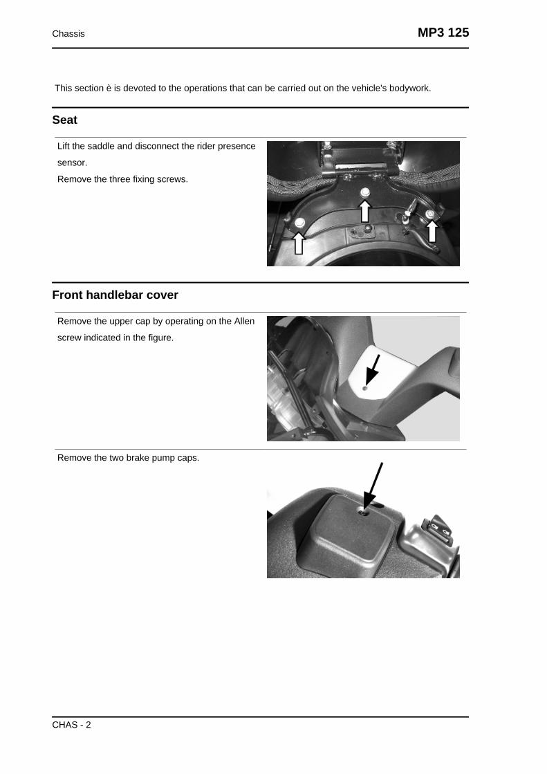
This section è is devoted to the operations that can be carried out on the vehicle's bodywork.
Seat
Lift the saddle and disconnect the rider presence
sensor.
Remove the three fixing screws.
Front handlebar cover
Remove the upper cap by operating on the Allen
screw indicated in the figure.
Remove the two brake pump caps.
Chassis MP3 125
CHAS - 2

Remove the two screws under the brake pump
caps previously removed.
Unscrew the two pairs of screws in the lower part
of the half-handlebar.
After removing the front part of the handlebar cov-
er, access the two screws fixing the rear part to the
handlebar, as indicated in the photograph.
Headlight assy.
Remove the radiator cover.
Remove the two wheelhouses with the turn indi-
cator.
Unscrew the two screws fixing the wheelhouse to
the shield.
Disconnect the cable guide; after that, turn the
wheelhouse anticlockwise (inwards) to release it
from the shield supports.
MP3 125 Chassis
CHAS - 3

To remove the shield central finishing, remove the
PIAGGIO clip-on badge paying attention not to
spoil the paint, unscrew the screw underneath and
remove the finish carefully.
Remove the four screws "A" and disconnect the
wiring.
See alsoRadiator cover
Frame central cover
Remove the three screws on the right and the left
side.
Open the refuelling compartment and remove the
tank cap so as to remove the central cover.
Disconnect the cable, refuelling compartment
opening.
See alsoHandles and top side fairingsKnee-guardSeat
Chassis MP3 125
CHAS - 4
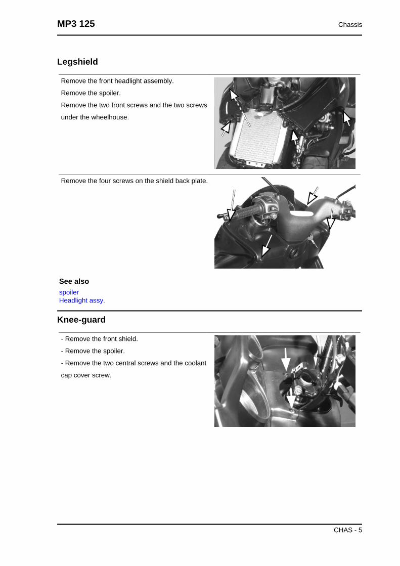
Legshield
Remove the front headlight assembly.
Remove the spoiler.
Remove the two front screws and the two screws
under the wheelhouse.
Remove the four screws on the shield back plate.
See alsospoilerHeadlight assy.
Knee-guard
- Remove the front shield.
- Remove the spoiler.
- Remove the two central screws and the coolant
cap cover screw.
MP3 125 Chassis
CHAS - 5

- Remove the expansion tank fixing screw and the
frame from the instrument panel and manually re-
lease the unions with the shield back plate.
- Unhook the instrument panel wiring.
- Remove the six screws and the cable guide strap
in the front part of the shield back plate.
Chassis MP3 125
CHAS - 6
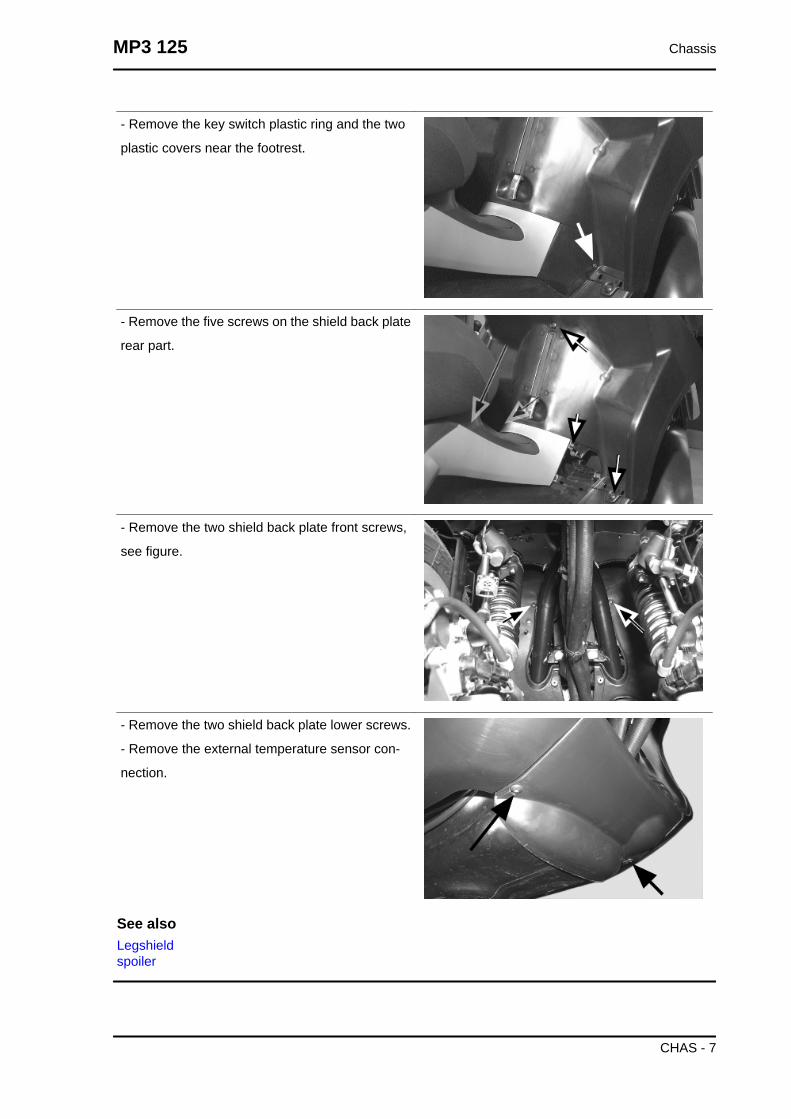
- Remove the key switch plastic ring and the two
plastic covers near the footrest.
- Remove the five screws on the shield back plate
rear part.
- Remove the two shield back plate front screws,
see figure.
- Remove the two shield back plate lower screws.
- Remove the external temperature sensor con-
nection.
See alsoLegshieldspoiler
MP3 125 Chassis
CHAS - 7

Taillight assy.
Open the rear case cover, remove the two screws
«D», and then, the other four fixing screws «D» to
pull out the headlight assembly from its fitting.
Follow this procedure to remove the bulbs:
Remove the snap-on bulbs «B».
Remove the bulbs «A» on the bayonet by turning
them 30° clockwise.
Footrest
Remove the central cover.
Remove the four screws and extract the half-foot-
rest.
Follow the same procedure for both half-footrests.
Release the fuse-box
See also
Chassis MP3 125
CHAS - 8
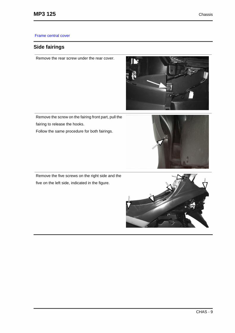
Frame central cover
Side fairings
Remove the rear screw under the rear cover.
Remove the screw on the fairing front part, pull the
fairing to release the hooks.
Follow the same procedure for both fairings.
Remove the five screws on the right side and the
five on the left side, indicated in the figure.
MP3 125 Chassis
CHAS - 9

License plate holder
Remove the two lateral screws and the two screws
inside the rear case.
Operate a slight upwards thrust on the case to re-
lease license plate support from the chassis.
Helmet bay
Remove the chassis central cover.
Remove the four external screws and the two
screws inside the rear case to remove the frame.
Chassis MP3 125
CHAS - 10
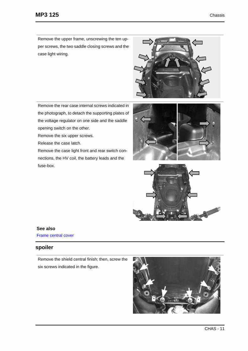
Remove the upper frame, unscrewing the ten up-
per screws, the two saddle closing screws and the
case light wiring.
Remove the rear case internal screws indicated in
the photograph, to detach the supporting plates of
the voltage regulator on one side and the saddle
opening switch on the other.
Remove the six upper screws.
Release the case latch.
Remove the case light front and rear switch con-
nections, the HV coil, the battery leads and the
fuse-box.
See alsoFrame central cover
spoiler
Remove the shield central finish; then, screw the
six screws indicated in the figure.
MP3 125 Chassis
CHAS - 11
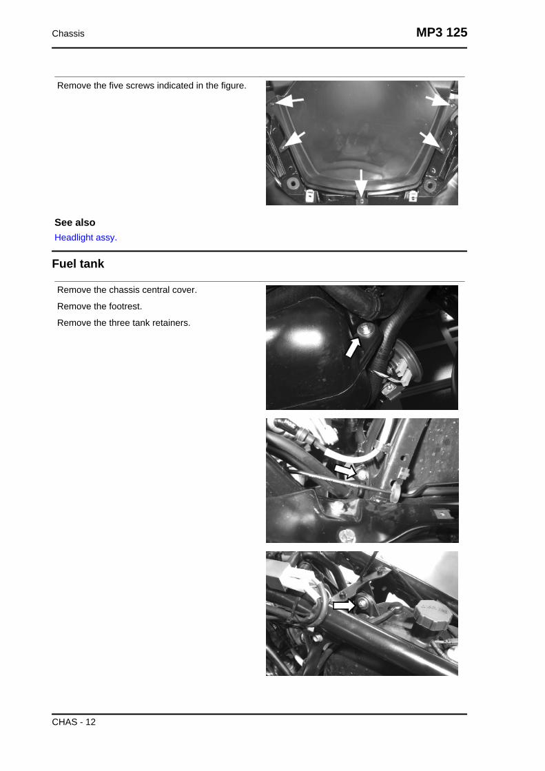
Remove the five screws indicated in the figure.
See alsoHeadlight assy.
Fuel tank
Remove the chassis central cover.
Remove the footrest.
Remove the three tank retainers.
Chassis MP3 125
CHAS - 12

Remove the two lower bracket retainers indicated
in the figure.
Disconnect the electric wiring and the fuel pipes.
See alsoFootrest
Remove the chassis central cover.
Remove the footrest.
Remove the three tank retainers.
MP3 125 Chassis
CHAS - 13

Remove the two lower bracket retainers indicated
in the figure.
Disconnect the electric wiring and the fuel pipes.
See alsoFootrest
Top-case
Rear
Remove the four fixing screws of the cover and
release it from the two leverages.
Handles and top side fairings
Remove the six screws indicated in the figure.
Chassis MP3 125
CHAS - 14

Radiator cover
Remove the two front screws indicated in the pho-
tograph
Remove the two lower retainers with the bushing
Remove the two rear retainers and then, the two
wheelhouse front retainers.
Remove the two screws fixing the radiator lower
protection to the shield back plate.
After that, press up and pull the protection front
part so as to release it from the radiator frame.
MP3 125 Chassis
CHAS - 15

Chassis MP3 125
CHAS - 16

INDEX OF TOPICS
PRE-DELIVERY PRE DE

Carry out the listed tests before delivering the vehicle.
Warning- be very careful when handling fuel.
Position the plastic cover supplied with the cou-
pling on the steering tube as shown in the figure.
Aesthetic inspection
Appearance check:
- Paintwork
- Fitting of plastics
- Scratches
- Dirt
Tightening torques inspection
Lock check
- Safety locks
- clamping screws
Safety locks
• Rear shock absorber upper fixing
• Rear shock absorber lower fixing
• Front shock absorber upper fixing
• Front shock absorber lower fixing
• Sliding stems fixing
• Break callipers fixing
• Front wheels fixing screws
• Front wheels axle nut
• Rear wheel axle nut
• Chassis - engine swinging arm fixing
• Handlebar lock nut
• Lower ring nut for side steering tubes
• Upper ring nut for side steering tubes
Pre-delivery MP3 125
PRE DE - 2

• Lower ring nut for central steering tube
• Upper ring nut for central steering tubes
• Constant-velocity universal joints
Electrical system
• Battery
• Main switch
• Lights: high beams, low beams, side/taillights (front and rear) and relevant warning lights
- Regulating the headlights according to the regulations currently in force
• Front and rear stop light buttons and bulb
• Turn indicators and their warning lights
• Instrument lighting
• instruments: fuel and temperature indicator
•Instrument panel lights
• Horn
• electric start up
• Engine stopping with emergency stop switch
• Electric opening of saddle with remote control
• Tilting system locking - unlocking buttonCAUTIONTO ENSURE MAXIMUM PERFORMANCE, THE BATTERY MUST BE CHARGED BEFORE USE.INADEQUATE CHARGING OF THE BATTERY WITH A LOW LEVEL OF ELECTROLYTE BEFOREIT IS FIRST USED SHORTENS THE LIFE OF THE BATTERY.CAUTIONWHEN INSTALLING THE BATTERY, ATTACH THE POSITIVE LEAD FIRST AND THEN THE NEG-ATIVE LEAD.WARNINGBATTERY ELECTROLYTE IS TOXIC AND IT MAY CAUSE SERIOUS BURNS. IT CONTAINS SUL-PHURIC ACID. AVOID CONTACT WITH EYES, SKIN AND CLOTHING.IN CASE OF CONTACT WITH EYES OR SKIN, RINSE WITH ABUNDANT WATER FOR ABOUT 15MINUTES AND SEEK MEDICAL ATTENTION AT ONCE.IF IT IS SWALLOWED, IMMEDIATELY DRINK LARGE QUANTITIES OF WATER OR VEGETABLEOIL. SEEK IMMEDIATE MEDICAL ATTENTION.THE BATTERIES PRODUCE EXPLOSIVE GAS; KEEP THEM AWAY FROM NAKED FLAMES,SPARKS AND CIGARETTES. IF THE BATTERY IS CHARGED IN A CLOSED PLACE, TAKE CARETO ENSURE ADEQUATE VENTILATION. ALWAYS PROTECT YOUR EYES WHEN WORKINGCLOSE TO BATTERIES.KEEP OUT OF THE REACH OF CHILDRENCAUTIONNEVER USE FUSES WITH A CAPACITY HIGHER THAN THE RECOMMENDED CAPACITY. USINGA FUSE OF UNSUITABLE RATING MAY SERIOUSLY DAMAGE THE VEHICLE OR EVEN CAUSEA FIRE.
Levels check
Level check:
MP3 125 Pre-delivery
PRE DE - 3

- Hydraulic brake system liquid level.
- Tilt locking system fluid level
- Rear hub oil level
- Engine coolant level
- Engine oil level
Road test
Test ride
- Cold start
- Instrument operations
- Response to the gas command
- Stability on acceleration and braking
- Rear and front brake efficiency
- Parking brake efficiency
- Rear and front suspension efficiency
- Abnormal noise
- Tilting system locking - unlocking efficiency
Static test
Static control after the test ride:
• Hot engine restart
• Minimum seal (turning the handlebar)
• Uniform steering rotation
• Possible losses
• electric radiator fan operationCAUTION
CHECK AND ADJUST TYRE PRESSURE WITH TYRES AT AMBIENT TEMPERATURE.CAUTION
NEVER EXCEED THE RECOMMENDED INFLATION PRESSURES OR TYRES MAY BURST.
Functional inspection
Functional check up:
• Hydraulic braking system: lever travel
• Clutch: proper functioning check
• Engine: proper general functioning and no abnormal noise check
• Other: papers check, frame and engine number check, tools and equipment, licence plate fitting, lock
check, tyre pressure check, rear-view mirror and any accessory fitting
Pre-delivery MP3 125
PRE DE - 4

MP3 125 Pre-delivery
PRE DE - 5

Pre-delivery MP3 125
PRE DE - 6

INDEX OF TOPICS
TIME TIME

This section is devoted to the time necessary to carry out repairs.
For each operation, the description, code and time envisages are specified.
Engine
ENGINECode Action Duration
1 001001 Engine from chassis - Re-moval and refit.
2 001127 Engine - Complete service3 003064 Engine oil - Change
Time MP3 125
TIME - 2

Crankcase
CRANKCASECode Action Duration
1 001133 Engine crankcase- Replace-ment
2 001099 Oil seal, flywheel side - Re-placement
3 001100 Oil seal, clutch side - Re-placement
4 001124 Lubrication by-pass - Re-placement
5 001153 Crankcase halves gasket -Replacement
MP3 125 Time
TIME - 3

Crankshaft
CRANKSHAFTCode Action Duration
1 001117 Crankshaft - Replacement
Time MP3 125
TIME - 4
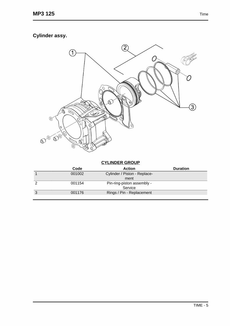
Cylinder assy.
CYLINDER GROUPCode Action Duration
1 001002 Cylinder / Piston - Replace-ment
2 001154 Pin-ring-piston assembly -Service
3 001176 Rings / Pin - Replacement
MP3 125 Time
TIME - 5

Cylinder head assy.
HEAD UNITCode Action Duration
1 001057 Thermostat - Replacement2 007012 Coolant bleed valve - Re-
placement3 001083 Thermistor - Replacement4 001056 Head gasket - Replacement5 001045 Valves - Replacement6 001049 Valves - Adjustment
Time MP3 125
TIME - 6

Rocker arms support assy.
ROCKING LEVERS SUPPORTING UNITCode Action Duration
1 001148 Valve rocking levers - Re-placement
2 001126 Head - Replacement3 001044 Camshaft - Replacement
MP3 125 Time
TIME - 7

Cylinder head cover
HEAD COVERCode Action Duration
1 001089 Head cover - Replacement2 001093 Spark plug - Replacement3 001088 Head cover gasket - Replace-
ment4 001074 Oil vapour recovery pipe - Re-
placement5 001159 Oil vapour recovery tank -
Service
Time MP3 125
TIME - 8
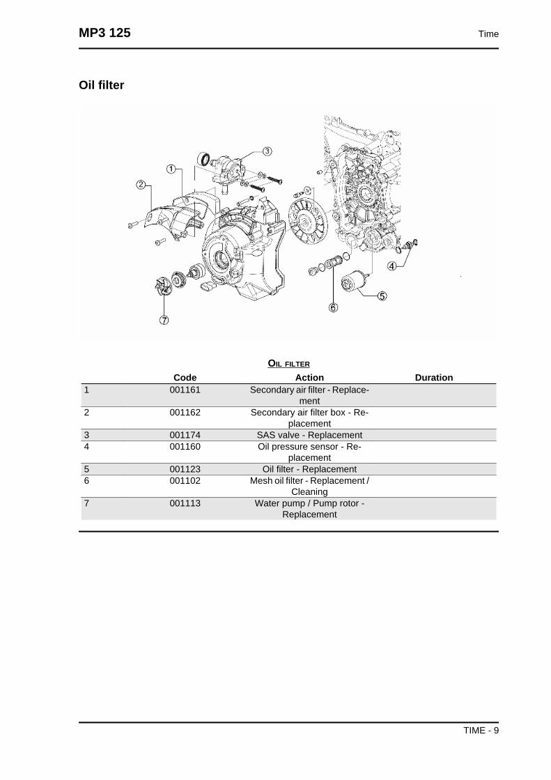
Oil filter
OIL FILTER
Code Action Duration1 001161 Secondary air filter - Replace-
ment2 001162 Secondary air filter box - Re-
placement3 001174 SAS valve - Replacement4 001160 Oil pressure sensor - Re-
placement5 001123 Oil filter - Replacement6 001102 Mesh oil filter - Replacement /
Cleaning7 001113 Water pump / Pump rotor -
Replacement
MP3 125 Time
TIME - 9

Driven pulley
DRIVEN PULLEYCode Action Duration
1 001012 Driven pulley - Service2 001022 Clutch - Replacement3 001110 Driven pulley - Replacement4 001155 Clutch bell - Replacement
Time MP3 125
TIME - 10

Oil pump
OIL PUMPCode Action Duration
1 001129 Chain tightener - Service andreplacement
2 001125 Chain guide pads - Replace-ment
3 001122 Oil pump chain - Replace-ment
4 001172 Chain cover flap - Replace-ment
5 001130 Oil sump - Replacement6 001042 Oil pump - Service7 001112 Oil pump - change8 001051 Belt/Timing chain - Change
MP3 125 Time
TIME - 11

Final gear assy.
FINAL REDUCTION GEAR ASSEMBLYCode Action Duration
1 002031 Rear wheel hub bearings -Replacement
2 003065 Gear box oil - Replacement3 004180 Reduction gear breather pipe
- Replacement4 004125 Rear wheel axle - Replace-
ment5 001179 Hub drive shaft -replacement6 001156 Gear reduction unit cover -
Replacement
Time MP3 125
TIME - 12

Driving pulley
DRIVING PULLEYCode Action Duration
1 001177 Variator rollers / shoes - Re-placement
2 001066 Driving pulley - Removal andRefitting
3 001006 Driving pulley - Service4 001086 Driving half-pulley - Replace-
ment5 001011 Driving belt - Replacement
MP3 125 Time
TIME - 13

Transmission cover
TRANSMISSION COVER
Code Action Duration1 001135 Transmission cover bearing -
Replacement2 001096 Transmission crankcase cov-
er - Replacement3 001131 Transmission air intake - Re-
placement4 001170 Air deflector - Replacement5 001132 Transmission air inlet pipe -
Replacement
Time MP3 125
TIME - 14

Water pump
WATER PUMP
Code Action Duration1 007009 Head-pump by-pass rubber
coupling - Replacement
MP3 125 Time
TIME - 15
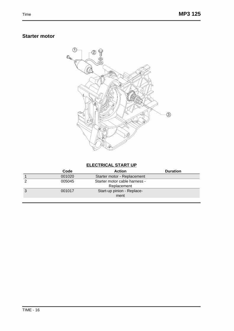
Starter motor
ELECTRICAL START UPCode Action Duration
1 001020 Starter motor - Replacement2 005045 Starter motor cable harness -
Replacement3 001017 Start-up pinion - Replace-
ment
Time MP3 125
TIME - 16

Flywheel magneto
MAGNETO FLYWHEELCode Action Duration
1 001067 Stator - Removal and Refit-ting
2 001058 Complete flywheel - Replace-ment
3 001173 Rotor - Replacement4 001087 Flywheel cover - Replace-
ment
MP3 125 Time
TIME - 17

Carburettor
CARBURETTOR
Code Action Duration1 001063 Carburettor - Replacement2 003058 Carburettor - Adjustment3 001013 Intake manifold - Replace-
ment
Time MP3 125
TIME - 18
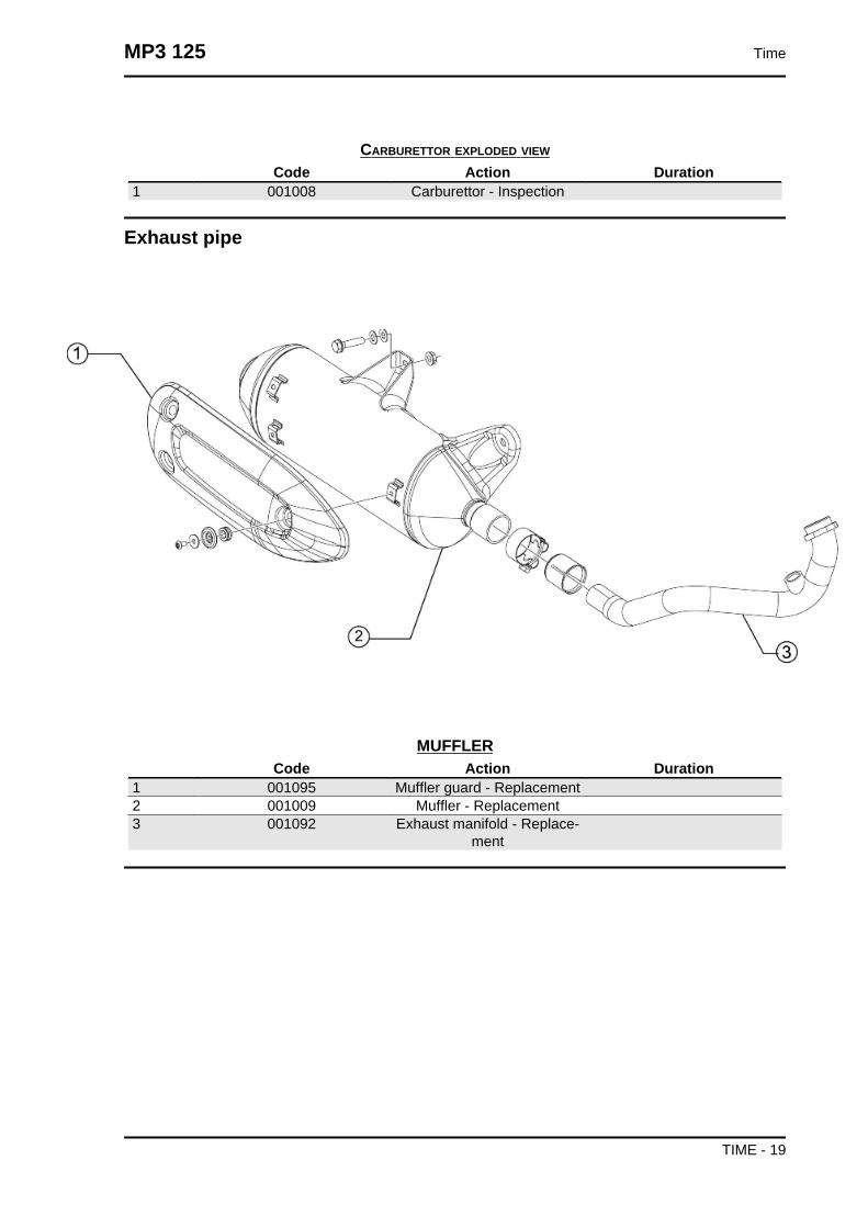
CARBURETTOR EXPLODED VIEW
Code Action Duration1 001008 Carburettor - Inspection
Exhaust pipe
MUFFLERCode Action Duration
1 001095 Muffler guard - Replacement2 001009 Muffler - Replacement3 001092 Exhaust manifold - Replace-
ment
MP3 125 Time
TIME - 19

Air cleaner
AIR CLEANERCode Action Duration
1 004122 Air cleaner carburettor fitting -Replacement
2 001014 Air filter - Replacement /cleaning
3 001015 Air filter box - Replacement
Time MP3 125
TIME - 20

Frame
CHASSIS
Code Action Duration1 004146 Front frame - Replacement2 004116 Rear frame - Replacement3 004001 Frame - replace4 004147 footboard support bracket
one side - Replacement5 004143 Footrest support - replace
MP3 125 Time
TIME - 21

Centre-stand
STANDCode Action Duration
1 001053 Stand bolt - Replacement2 004179 Stand buffer - Replacement3 004004 Stand - Replacement
Time MP3 125
TIME - 22

Legshield spoiler
FRONT SHIELD
Code Action Duration1 004020 Headlight frame - Replace-
ment2 004064 Front shield - Replacement3 004055 Turn indicator frame - Re-
placement4 004149 Shield central cover - Re-
placement5 004022 Shield lower section - Re-
placement6 004167 Grill / radiator cover - Re-
placement
MP3 125 Time
TIME - 23

Side fairings
SIDE COVERS
Code Action Duration1 004036 Lower chassis cover - Re-
placement2 004129 Rear fairing - Replacement3 004085 Fairing (1) - Replacement4 004068 Passenger handgrip - Re-
placement5 004037 Side aprons-Replacement
Time MP3 125
TIME - 24

Rear cover
REAR SHIELDCode Action Duration
1 004065 Front shield, rear part - Re-moval and refitting
MP3 125 Time
TIME - 25

Central cover
CENTRAL COVERCode Action Duration
1 004059 Spark plug inspection flap -Replacement
2 004135 Fuel tank lid - Replacement3 004011 Central chassis cover - Re-
placement4 004012 Rear fairings - Removal and
refitting5 004015 Footrest - Removal and Re-
fitting6 004075 Front mat - Replacement
Time MP3 125
TIME - 26

Mudguard
MUDGUARDSCode Action Duration
1 007015 Radiator air intake - Replace-ment
2 004009 Rear mudguard - Replace-ment
3 004181 Lower cover - Replacement4 004184 Front mudguard support - re-
placement5 004002 Front mudguard - Replace-
ment
MP3 125 Time
TIME - 27

Fuel tank
FUEL TANK
Code Action Duration1 004137 Injector pump pipe - Replace-
ment2 005010 Tank float - Replacement3 004168 Fuel tank cap - Replacement4 004005 Fuel tank - Replacement
Time MP3 125
TIME - 28

Rear shock-absorber
REAR SHOCK ABSORBERS
Code Action Duration1 003007 Rear shock absorber - Re-
moval and Refitting2 003035 Shock absorber support and
brake calliper - Replacement3 003077 muffler/rear shock absorber
support arm - Service
MP3 125 Time
TIME - 29

Handlebar covers
HANDLEBAR COVERSCode Action Duration
1 000307 RIGHT OR LEFT CONTROLASSEMBLY REPLACE-
MENT2 004019 Rear handlebar cover - Re-
placement3 004026 Handlebar cover - Replace-
ment4 004018 Front handlebar cover - Re-
placement
Time MP3 125
TIME - 30
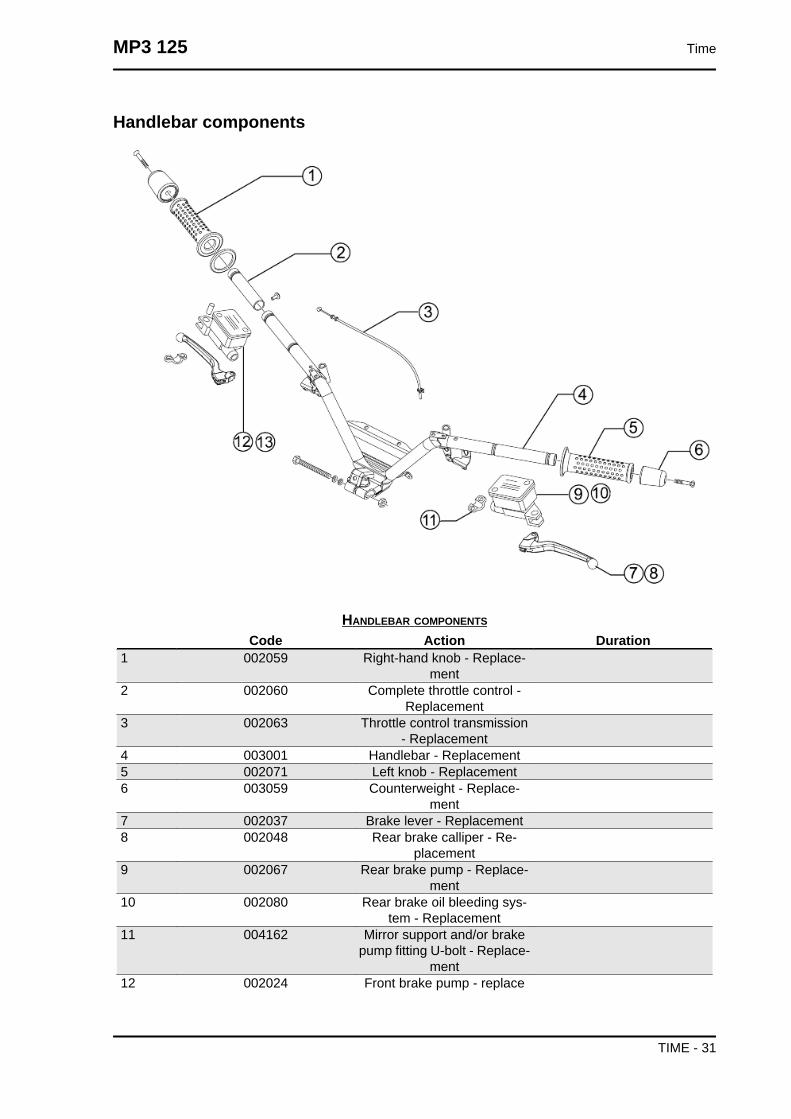
Handlebar components
HANDLEBAR COMPONENTS
Code Action Duration1 002059 Right-hand knob - Replace-
ment2 002060 Complete throttle control -
Replacement3 002063 Throttle control transmission
- Replacement4 003001 Handlebar - Replacement5 002071 Left knob - Replacement6 003059 Counterweight - Replace-
ment7 002037 Brake lever - Replacement8 002048 Rear brake calliper - Re-
placement9 002067 Rear brake pump - Replace-
ment10 002080 Rear brake oil bleeding sys-
tem - Replacement11 004162 Mirror support and/or brake
pump fitting U-bolt - Replace-ment
12 002024 Front brake pump - replace
MP3 125 Time
TIME - 31

Code Action Duration13 002047 Front brake fluid and air
bleeding system - Replace-ment
Swing-arm
SWINGING ARMCode Action Duration
1 004058 Silent block - Replacement2 003081 Swinging arm support flange
- replace3 001072 Swinging arm - Engine-chas-
sis connection - Replacement4 003080 Swinging arm on frame - Re-
placement
Time MP3 125
TIME - 32

Seat
SADDLECode Action Duration
1 004003 Saddle - Replacement
MP3 125 Time
TIME - 33

Instrument panel
INSTRUMENT PANEL
Code Action Duration1 004021 Shield upper section - Re-
placement2 005014 Odometer - Replacement3 004099 Odometer housing - Replace-
ment4 004035 Instrument panel - Replace-
ment
Time MP3 125
TIME - 34

Locks
LOCKS
Code Action Duration1 004172 Rear case closure hook - Re-
placement2 005099 Electric saddle opening acti-
vator - Replacement3 004054 Saddle lock catch - Replace-
ment4 004001 Chassis - Replacement5 005072 Immobilizer aerial - Replace-
ment
Turn signal lightsRear lights
MP3 125 Time
TIME - 35

REAR TURN INDICATORS INDICATOR LIGHTS
Code Action Duration1 005005 Taillight - Replacement2 005022 Rear turn indicators - Re-
placement3 005031 Licence plate light bulb - Re-
placement4 005032 Licence plate light glass - Re-
placement5 005131 Licence plate light support -
Replacement6 005066 Rear light bulbs - Replace-
ment7 005068 Rear turn indicator bulb - Re-
placement
Front lights
Time MP3 125
TIME - 36

FRONT TURN INDICATORS INDICATOR LIGHTS
Code Action Duration1 005067 Front turn indicator bulb - Re-
placement2 005012 Front turn indicators - Re-
placement3 005002 Front light - replacement4 005008 Headlight bulbs - Replace-
ment
MP3 125 Time
TIME - 37

Front wheel
FRONT WHEELS
Code Action Duration1 003047 Front tyre - Replacement2 003033 Front wheel hub- Replace-
ment3 003037 Front wheel rim- Replace-
ment4 005089 Tone wheel - Replacement5 002041 Front brake disc - Replace-
ment6 004123 Front wheel - Replacement
Time MP3 125
TIME - 38

Rear wheel
REAR WHEEL
Code Action Duration1 002070 Rear brake disc - Replace-
ment2 001016 Rear wheel - Replacement3 001071 Front wheel rim - Removal
and refitting4 004126 Rear wheel tyre - Replace-
ment
MP3 125 Time
TIME - 39

Electric devices
ELECTRICAL DEVICES
Code Action Duration1 005075 Stop remote control - Re-
placement2 005035 Headlight remote control -
Replacement3 005011 Start-up remote control
switch - Replacement4 005007 Battery - Replacement5 005003 Horn - Replacement
Time MP3 125
TIME - 40
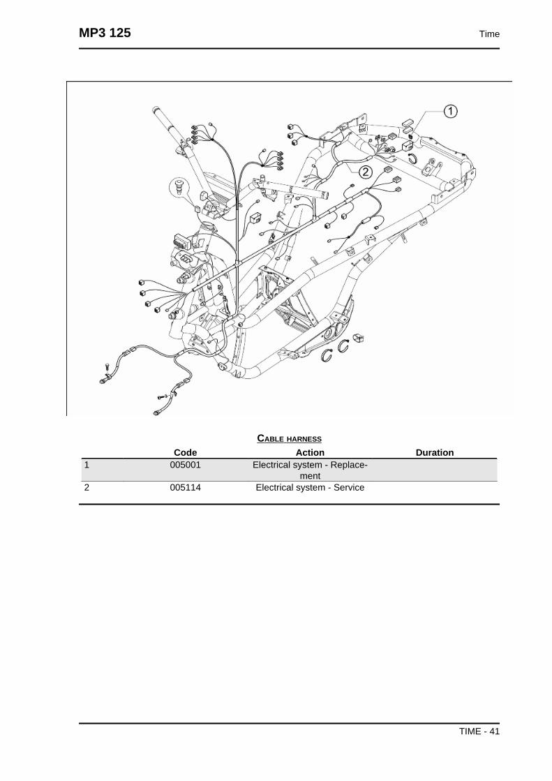
CABLE HARNESS
Code Action Duration1 005001 Electrical system - Replace-
ment2 005114 Electrical system - Service
MP3 125 Time
TIME - 41

Electronic controls
HANDLEBAR CONTROLS
Code Action Duration1 005017 Stop switch - Replacement2 005077 Emergency stop switch - Re-
placement3 005041 Starter button - Replacement4 004010 Antitheft lock - Replacement5 005040 Horn button - Replacement6 005006 Light or turn indicator switch -
Replacement7 005039 Headlight switch - Replace-
ment
Time MP3 125
TIME - 42

Transmissions
LOCKS TRANSMISSIONS
Code Action Duration1 003094 Tilt locking calliper control ca-
ble - replacement2 002082 Fuel tank cap opening drive -
Replacement3 002083 Saddle opening transmission
- Replacement4 002093 Trunk opening transmission -
Replacement5 003061 Accelerator transmission -
Adjustment
MP3 125 Time
TIME - 43
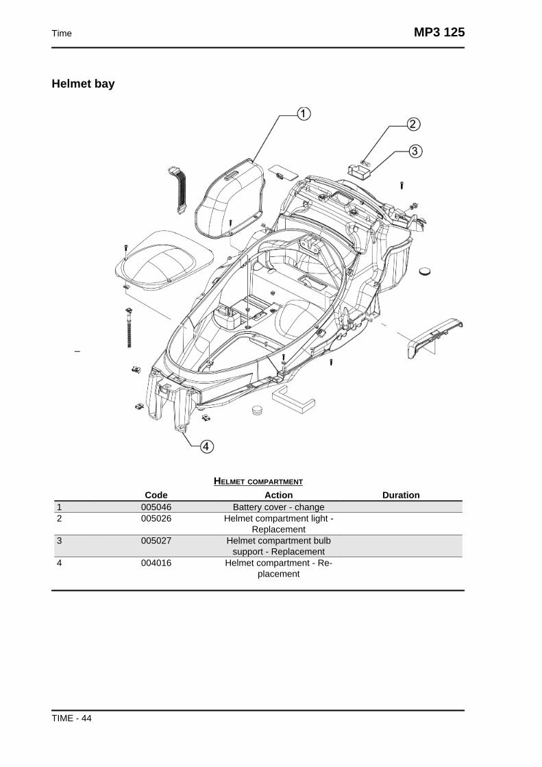
Helmet bay
HELMET COMPARTMENT
Code Action Duration1 005046 Battery cover - change2 005026 Helmet compartment light -
Replacement3 005027 Helmet compartment bulb
support - Replacement4 004016 Helmet compartment - Re-
placement
Time MP3 125
TIME - 44

Rear side fairings
REAR COVERS
Code Action Duration1 004081 Glove box door - Replace-
ment2 004174 Trunk leverage3 004141 Cat's eye - Replacement4 005048 Licence plate holder - Re-
placement5 004082 Trunk gasket - Replacement
MP3 125 Time
TIME - 45

Front suspension
FRONT SUSPENSIONCode Action Duration
1 003010 Front suspension - Service2 003111 Side steering tube - replace-
ment3 003038 Front wheel axle - Removal
and Refit.4 003040 Front wheel bearings - Re-
placement5 003107 Sliding stems - replacement6 003113 Front shock absorber - re-
placement
Time MP3 125
TIME - 46

Cooling system
COOLING SYSTEM
Code Action Duration1 007013 Expansion tank - radiator
connection pipe - Replace-ment
2 001052 Coolant and air bleed - Re-placement
3 007001 Expansion tank - Replace-ment
4 007024 Expansion tank cap - Re-placement
5 007003 Coolant delivery and returnpipe - Replacement
6 007016 Fan with support - Replace-ment
7 007002 Water radiator - replacement
MP3 125 Time
TIME - 47

Braking system
BRAKE SYSTEM
Code Action Duration1 002025 Brake piping - Replacement2 003096 Tilt locking calliper- replace-
ment3 003100 Tilt locking calliper pads - re-
placement4 003108 Parking brake flexible trans-
mission - replacement5 003109 Parking brake mechanical
calliper - replacement6 002002 Shoes - Rear brake pads -
Replacement7 002020 Rear brake pipes - Removal
and refitting8 002081 Rear brake disc piping - Re-
placement9 003118 Tilt locking disc section - re-
placement
Time MP3 125
TIME - 48

Code Action Duration10 003103 Splitter for suspension lock-
ing system hoses- replace-ment
11 003102 Hoses for the splitter-callipersuspension locking system -
replacement12 003088 Tilt locking hydraulic pump -
replacement13 002021 Front brake piping - Replace-
ment14 002007 Front brake pads - Replace-
ment15 002039 Front brake calliper - Re-
placement16 003104 Suspension system locking
calliper- replacement17 003119 Hoses for the pump-splitter
suspension locking system -replacement
18 003105 Suspension locking systembrake fluid - repl.
19 003106 Suspension locking systempressure sensor-Replace-
ment
Windscreen
MP3 125 Time
TIME - 49

WINDSHIELDCode Action Duration
1 004101 Windshield - Replacement
Secondary air box
SECONDARY AIR HOUSING
Code Action Duration1 001163 SAS valve / Head connection
- Replacement
Time MP3 125
TIME - 50
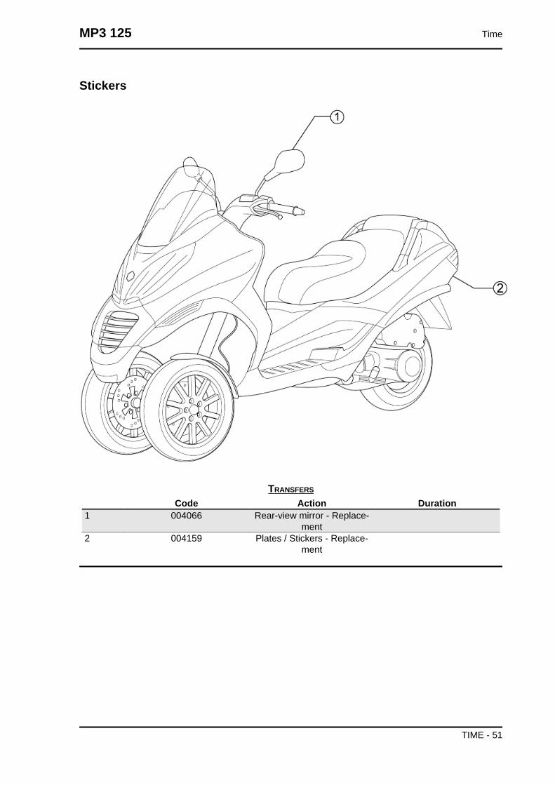
Stickers
TRANSFERS
Code Action Duration1 004066 Rear-view mirror - Replace-
ment2 004159 Plates / Stickers - Replace-
ment
MP3 125 Time
TIME - 51

The tilt mechanism
TILT MECHANISM
Code Action Duration1 003073 Steering clearance - Adjust-
ment2 003112 Central steering tube - re-
placement3 003002 Steering fifth wheel - Re-
placement4 003115 Parallelogram arms - re-
placement5 003114 Parallelogram bearings - re-
placement6 003116 Steering rod - replacement7 003117 Constant-velocity universal
joint - replacement
Time MP3 125
TIME - 52
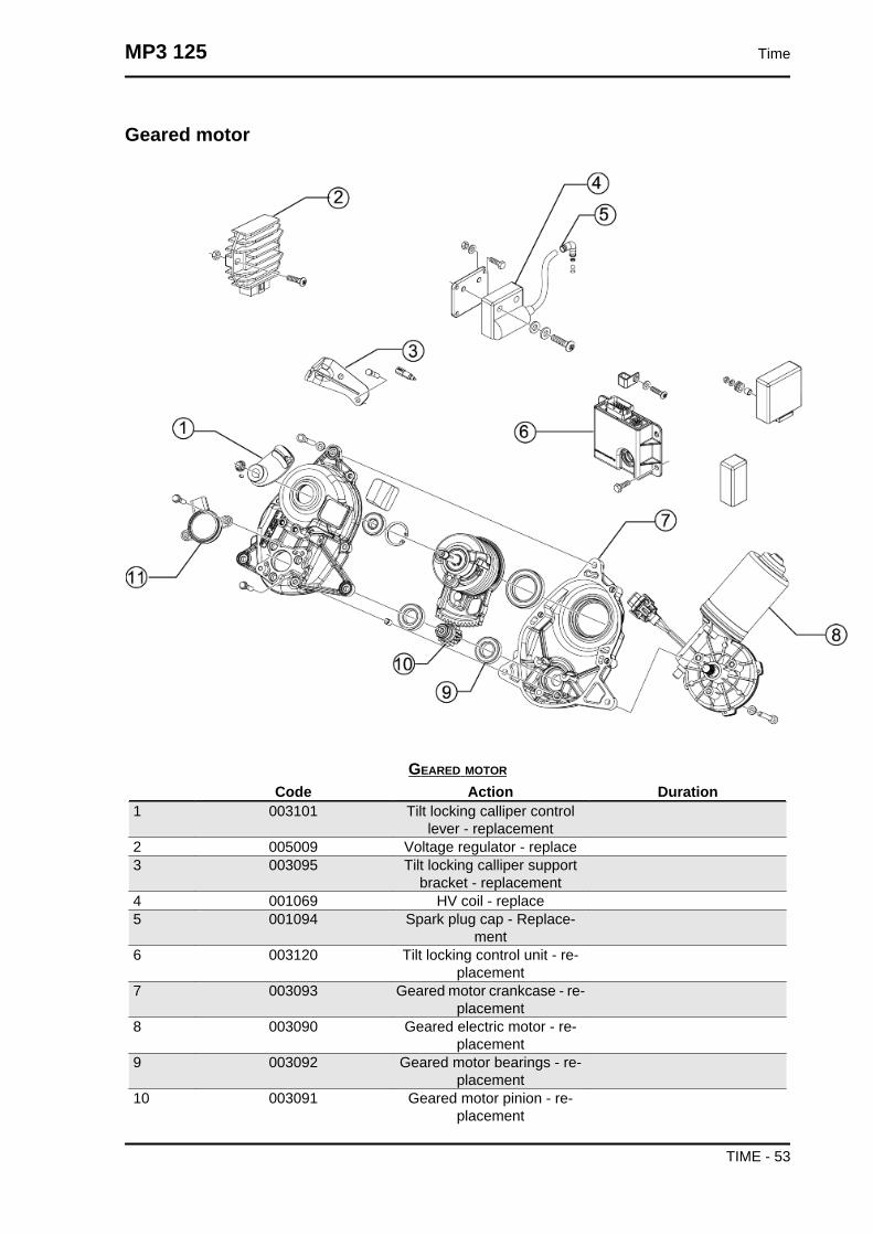
Geared motor
GEARED MOTOR
Code Action Duration1 003101 Tilt locking calliper control
lever - replacement2 005009 Voltage regulator - replace3 003095 Tilt locking calliper support
bracket - replacement4 001069 HV coil - replace5 001094 Spark plug cap - Replace-
ment6 003120 Tilt locking control unit - re-
placement7 003093 Geared motor crankcase - re-
placement8 003090 Geared electric motor - re-
placement9 003092 Geared motor bearings - re-
placement10 003091 Geared motor pinion - re-
placement
MP3 125 Time
TIME - 53

Code Action Duration11 003089 Geared motor potentiometer
- replacement
Time MP3 125
TIME - 54


