National Asset Delivery TST - ECSC Works Information
TST, Issue 2, Revision 3 July 2019
Page 1 of 29
National Asset Delivery
Technical Surveys and Testing
Works Information for Wynhol Viaduct
Lower Northbound M5 151.30/B and
Wynhol Viaduct Upper Southbound M5
151.30/A

National Asset Delivery TST - ECSC Works Information
TST, Issue 2, Revision 3 July 2019
Page 2 of 29
CONTENTS AMENDMENT SHEET
Amend.
No.
Revision
No. Amendments Initials Date
0 0 Original version issued with tender ET 13/10/2020
National Asset Delivery TST - ECSC Works Information
TST, Issue 2, Revision 3 July 2019
Page 3 of 29
TABLE OF CONTENTS
1 Description of the works .................................................................................... 4
1.1 Project Objectives .......................................................................................... 4
1.2 Scope of works .............................................................................................. 4
1.2.1 Corrosion Test Areas ..................................................................................... 5
1.2.2 Trial Pitting Works and Works Associated with Trial Pitting Activities ........... 8
1.2.3 Inspection of Bearings ................................................................................. 10
1.2.4 Inspection of Expansion joints ..................................................................... 11
1.2.5 Dilapidation Survey ...................................................................................... 11
1.3 Deliverables ................................................................................................. 12
2. Existing Information ......................................................................................... 15
3. Constraints on how the Contractor Provides the Works .............................. 18
3.1 General ........................................................................................................ 18
3.2 Working hours & site specific constraints ......................................................... 18
3.3 Recommended concurrence / phasing of works .............................................. 19
3.4 Health, Safety and Environment & Risk Management ................................. 20
4. Requirements for the programme ................................................................... 22
5 Services and other things provided by the Employer ................................... 23
6 Specification for the works .............................................................................. 24
List of Appendices
Appendix A Test Areas Information
Appendix B Test Areas Location Plan

National Asset Delivery TST - ECSC Works Information
TST, Issue 2, Revision 3 July 2019
Page 4 of 29
1 DESCRIPTION OF THE WORKS
1.1 Project Objectives
1.1.1 The following specification sets out the investigation requirements required to
assess durability of the Wynhol Viaducts - Lower Northbound and Upper
Southbound and options to extend their serviceable lifespan.
1.1.2 The specification that applies to the Works is included in Section 6.
1.1.3 The requirements contained in GG 101 shall be followed in respect of
activities covered by this document.
1.2 Scope of works
The Works to be provided under this contract are:
Undertake structural testing surveys as detailed in this section, the Specification in
Section 6 and Appendices. To determine the appropriate level of information, the
Contractor shall perform the following investigations:
1) Corrosion Test Areas (Sections 1.2.1 and 1.2.2) comprising;
a) Delamination Survey
b) Concrete cover survey
c) Half-cell Potential survey
d) Concrete resistivity measurements
e) Depth of carbonation
f) Chloride ion contents determination
g) Cement contents determination
h) Sulfate contents determination
i) Alkali contents determination
2) Deck waterproofing investigations (Section 1.2.2);
3) Bearing Inspection (Section 1.2.3);
4) Expansion Joint Inspection (Section 1.2.4);
5) Dilapidation survey (Section 1.2.5);
6) Material sampling and Waste Acceptance Criteria (WAC) testing of materials
requiring disposal arising from these investigations (Section 1.2.2).
National Asset Delivery TST - ECSC Works Information
TST, Issue 2, Revision 3 July 2019
Page 5 of 29
Other surveys are to be separately commissioned as part of this project. The
Contractor shall consider the programme of the works is to run concurrently with other
planned works provided at contract award by Highways England, in order to fully utilise
road space and Traffic Management. As these other planned works are specified under
a separate procurement method, the works have not yet been programmed. Highways
England are to specify the dates for site works, and provide the Contractor with relevant
information (i.e. programme and relevant contact details for others, and concurrent
works) and sufficient lead time to enable effective mobilisation.
1.2.1 Corrosion Test Areas
Locations of Corrosion Test Areas (CTAs), with CTA types, referencing, size and
dimensions are detailed in Appendix A. A CTA location plan is detailed in Appendix B.
It is proposed to undertake Corrosion Test Areas (CTAs) in 14 No. areas per structure,
as detailed in Appendices A and B.
The required standards for testing are detailed in Section 6. Reporting requirements
are set out in Section 1.3.
The scope of these investigations is as follows:
(1) The Contractor shall carry out a comprehensive delamination /
hammer tap survey on all the concrete elements within the full extent
and immediate vicinity of Corrosion Test Areas (i.e. an additional 0.5m
around the edge of the CTA). The delamination survey shall be
undertaken to determine the extent of any “hollow” or “ringing” spots
which indicates the early onset of delamination or spalling. The
location and the extent of any loose, detached, or ‘drummy’ sections
of concrete shall be recorded and reported. The location, extent and
section loss of any exposed reinforcement shall additionally be
recorded and reported.
(2) Any concrete identified as loose, or which poses a threat to the public
or the maintenance staff shall be fully removed. Highways England are
to be made aware of areas of spalled concrete above 0.3m x 0.3m, or
where reinforcement is exposed due to spalling, where loose concrete
is removed.
(3) An electromagnetic cover meter shall be used to detect reinforcement
bars positioned parallel and perpendicular to the concrete surfaces.
The cover meter survey shall be used to locate the reinforcement prior
to half-cell and resistivity surveys. The cover meter survey shall be
used to avoid steel reinforcement and post-tensioned cables in drilling
holes for carbonation test and dust samples.
(4) The size of CTAs is detailed within Appendix A, but the dimensions
can be altered to suit the size and shape of the element being
investigated and level of associated risk. Readings shall be taken at
0.5m x 0.5m grid spacings within the test areas to determine the
National Asset Delivery TST - ECSC Works Information
TST, Issue 2, Revision 3 July 2019
Page 6 of 29
minimum concrete cover in that area, unless this is impractical, in
which case nodes at smaller centres covering approximately the same
size test panel as proposed in Appendix A is acceptable.
(5) An electrical potential survey using half-cell test equipment shall be
carried out at node points defined by a grid marked on the concrete
within the test areas and shall be undertaken on sound and non-
delaminated concrete. Electrical continuity of the reinforcement shall
be checked and confirmed prior to carrying out the corrosion potential
survey. Portable silver/silver chloride reference electrode (SSC [0.5M
KCl], Ag/AgCl/0.5M KCl) should be used for half-cell potential surveys
and results shall be recorded in millivolts (mV).
The ASTM C876 [Ref 27.I] infers that a saturated copper/copper
sulfate electrode (CSE) is the normal reference electrode used for
measuring corrosion potential using half-cell survey. The advice
reflects practice in the United States, but use of a CSE electrode is not
recommended in the UK. Significant errors can arise from the use of
CSE electrodes and their use is discouraged.
(6) Half-cell potential measurements shall be undertaken at 0.5m x 0.5m
grid spacings over the proposed test panels. The survey grid spacing
may be reduced near to vulnerable areas (such as joints) or if the
potential gradient is greater than 100mV between readings taken at
0.5m x 0.5m spacings.
(7) Where corrosion potential readings indicate there is a high risk of
reinforcement corrosion (-300mV for SSC probe and -350 mV for CSE
probe), but concrete is intact with no detectable delamination, the
actual condition of the reinforcement shall be investigated by
exploratory breakout. A small grid CTA is to be undertaken
surrounding any nodes where the electrical potential exceeds the
threshold for the potential onset of pitting corrosion. Half-cell potential
measurements within small grid CTAs are to be undertaken at 0.1m x
0.1m nodes, within a 0.5m x 0.5m area. Additional chloride sampling
and resistivity measurements are to be undertaken at the location of
the lowest reading and a localised reinforcement breakout is to be
made to allow visual inspection of the steel.
(8) Where small breakouts are necessary to enable electrical connections
to the reinforcing steel, they shall be reinstated as per Section 1.2.1
Clause (16) of this document. Breakouts undertaken to facilitate
connection to reinforcement (half-cell potential survey) shall be used
to confirm reinforcement type, orientation, size, cover and condition.
Furthermore, where corrosion potential readings indicate there is a
high risk of reinforcement corrosion (-300 mV for SSC probe and -350
mV for CSE probe), local concrete breakout to check for initiation and
severity of rebar corrosion shall be undertaken.
National Asset Delivery TST - ECSC Works Information
TST, Issue 2, Revision 3 July 2019
Page 7 of 29
(9) Concrete resistivity measurements shall be carried out at the locations
of the most negative half-cell potential values, at a minimum of two
locations per test panel. The resistivity of the concrete shall be
measured using electrodes temporarily attached to the concrete,
across which measurements of voltage and current are taken. These
measurements may be taken using a four-probe array or a two-probe
array system. Probes shall be placed in holes drilled through the
carbonated surface layer and through the surface contamination (a
depth of 5 mm is considered sufficient), filled with a low resistivity
contact medium. If the system is spring-loaded, applied pressure is
considered sufficient to maintain electrical contact and as such these
holes do not need to be drilled. The concrete resistivity shall be
reported in units of kΩcm.
(10) The depth of carbonation shall be determined by testing freshly
exposed concrete using phenolphthalein indicator in ethanol. The test
shall be undertaken at each location where concrete has been drilled
to obtain samples for determination of chloride ion content. The depth
of carbonation at each location shall be recorded and supported with
photographic record.
(11) Chloride content tests shall be obtained from all test panels from
locations at the most negative electrical potentials measured. Samples
shall be removed from the concrete at a minimum of two locations
within each test area and be taken to a laboratory for testing (at the
location of the two lowest half-cell readings). Prior to drilling holes, the
position of existing reinforcement should be detected and marked on
the concrete to minimise the risk of damaging bars. The diameter of
sample holes should be small and a function of aggregate size.
Incremental samples shall be obtained at depths of 5-30mm, 30-
55mm, 55-80mm and 80-105mm. If there is a perceived risk of chloride
ingress (i.e. active / historic water leakage) beyond this depth, two
additional drillings to a total depth of 155mm are to be undertaken.
Each sample shall be sealed and uniquely labelled and weigh at least
25g.
(12) Sampling holes shall be reinstated as per Section 1.2 Clause (16) of
this document.
(13) Cement content, sulfate content and alkali content of concrete shall be
determined on dust and lump samples retrieved from breakouts used
to facilitate the inspection of reinforcement if highly negative half-cell
readings are found. If no breakouts are necessary to check
reinforcement condition, samples of concrete shall be collected from
half-cell connection locations. The cement content from locations not
associated with elevated corrosion potential shall be determined from
samples that are from representative locations as opposed to in one
relatively concentrated location.
National Asset Delivery TST - ECSC Works Information
TST, Issue 2, Revision 3 July 2019
Page 8 of 29
(14) Determination of alkali content, cement content and sulfate content
shall be undertaken from a minimum of three samples per structure at
representative locations. At least one sample from a pier, abutment
and deck soffit or top slab shall be tested per structure.
(15) The mean cement content as determined by laboratory testing shall
be used in the calculation of chloride ion content by mass of cement.
(16) All concrete removed from the structure, for the purposes of testing,
shall be reinstated with a high strength, non-shrink, quick setting,
proprietary mortar. Reinstatement material shall be placed in
accordance with the manufacturer’s instructions. All equipment used
for placing shall be clean and free from contaminants. The finished
surface shall have a colour and texture similar to that of the existing
concrete. Delaminated or spalled concrete does not need to be
reinstated.
1.2.2 Trial Pitting Works and Works Associated with Trial Pitting Activities
Trial pits are to be excavated within the carriageway at locations specified in Appendix
B.
Trial pit sizes are to be a minimum of 1.8m x 1.8m to accommodate corrosion testing.
There are to be three trial pits per structure (six total), all of which are to be utilised for
the following testing:
a) Waterproofing visual inspection and pull-off testing at three
locations per trial pit;
b) Corrosion Test Areas;
The required standards for testing are detailed in Section 6. Reporting requirements
are set out in Section 1.3.
The scope of these investigations is as follows:
(1) The trial pits are to be located and marked on the carriageway surface.
At trial pit locations, proposed work area shall be scanned using a
Cable Avoidance Tool (CAT) and Signal Generator (Genny). Statutory
undertakers’ drawings (Site Information Pack) are to be consulted and
a permit to dig shall be in place before works are to commence.
(2) At the two proposed trial pit locations adjacent to expansion joints
(north expansion joint, northbound (lower), south expansion joint,
southbound (upper)), initial pencil cores are to be undertaken at the
interface of the joint nosing with the carriageway surfacing to confirm
depth of surfacing and extents of waterproofing. The anticipated depth
of surfacing is 40mm but may vary up to 150mm.

National Asset Delivery TST - ECSC Works Information
TST, Issue 2, Revision 3 July 2019
Page 9 of 29
(3) The surfacing shall be saw cut with dust suppression methods used,
to the perimeter of the marked area, to the depth of surfacing. The
surfacing shall be broken out and spoil removed, to expose the
waterproofing layer within the full extent of the trial pit.
(4) The Contractor is to assume no asbestos is present in survey
locations, however, it is expected that the Contractor will have
Asbestos Awareness training for all site staff. A Refurbishment and
Demolition Asbestos Survey shall be undertaken by Others, prior to
disturbance of the waterproofing material within each trial pit, or any
intrusive works, in accordance with the requirements set out in Section
6. Record information indicated that the waterproofing system was
replaced in 1993 with a Servi-Deck / Servi-Pak system.
(5) The tensile pull-off method for adhesion testing shall be undertaken at
three locations within each trial pit, to ascertain the bonding properties
of the waterproofing to the bridge deck. Tests resulting in adhesive
(glue) failure are to be repeated, until results are obtained for a
different failure mode. Results of failure mode, alongside a detailed
description of the waterproofing type / properties and visual condition,
shall be recorded.
(6) The waterproofing layer is then to be fully removed within the extents
of the trial pit (except for a lap of 150mm or greater to enable a
sufficient bond to the waterproofing reinstatement material) to reveal
the concrete deck slab. The visual condition of the deck slab shall be
recorded. Corrosion testing shall be undertaken within each trial pit, in
alignment with the requirements set out in this document. Depths of
surfacing are to be recorded at all four corners of each trial pit.
(7) Reinstatement of waterproofing shall be undertaking using compatible
system with BBA certification, in accordance with manufacturer’s
instructions. Prior to reinstatement of the waterproofing, the bridge
deck shall be prepared by removing all traces of existing waterproofing
within the trial pit (with the exception of the lap) and abrading the
concrete to remove laitance and contamination.
(8) On completion of waterproofing reinstatement, the excavation shall be
reinstated using 12mm HRA surface course directly from a hot box.
Reinstatement shall be laid and compacted to leave a level finish with
the existing road surface. An appropriate number and thickness of lifts,
and number of compaction passes shall be determined by the
Contractor. The total minimum thickness of surfacing shall allow for
the existing surfacing depth. Joints are to be sealed using a compatible
sealant.
(9) A sample of the excavated spoil material shall be tested for the Waste
Acceptance Criteria and the presence of tar, to determine the
concentrations of leachable compounds and therefore determine
National Asset Delivery TST - ECSC Works Information
TST, Issue 2, Revision 3 July 2019
Page 10 of 29
disposal requirements prior to disposal at an appropriate site. All waste
materials are to be disposed of in accordance with relevant legislation
as set out in Section 6. A PAK marker spray test is also to be
undertaken on site to determine the presence of tar-bound materials
in the surfacing.
1.2.3 Inspection of Bearings & Freyssinet Hinges
For the inspection of the bearings and Freyssinet hinges, the Contractor is to remove
and reinstate existing cover plates and fixings (the existing cover plates can be re-
used, however new fixings may be required). Replacement fixings will be a like-for-like
replacement of existing to facilitate the inspection. The Contractor shall confirm the
existing fixing type and arrangement. Should the Contractor damage any of the cover
plates during removal, they shall submit a replacement cover plate design to the
Employer for acceptance and reinstate cover plates as per the accepted design.
Close visual inspection of all Freyssinet hinges to the tops and bottoms of piers shall
be undertaken and any visible deterioration shall be recorded. A localised hammer tap
survey shall be carried out as part of this inspection. The Contractor is to remove any
localised vegetation and excavate to fully inspect the Freyssinet hinges. The
Contractor shall deploy suitable environmental controls during any vegetation
clearance. Any excavation required is likely to be soft material affecting a localised
area, that can be excavated by hand digging. If particular difficulty arises exposing a
hinge, i.e. due to the volume of soil, an alternative hinge (another pier) may be
inspected. However, in this instance the Contractor shall identify an alternative location
where water leakage / other environmental conditions are likely to have adversely
affected the hinge.
Close visual inspection of all abutment bearings shall be undertaken. Bearings shall
be cleaned prior to the inspection to facilitate inspection of the components that
accommodate movement.
The following properties shall be checked and recorded:
a) Sufficient capacity for residual movement with respect to the type
of bearing/Freyssinet hinge, taking into account the temperature
of the structure;
b) Visible defects;
- Cracks;
- Incorrect position;
- Unforeseen movements and deformations;
c) Condition of bedding and fixing;
d) Condition of corrosion protection, dust protection and seals;
e) Condition of sliding and rolling surfaces;
National Asset Delivery TST - ECSC Works Information
TST, Issue 2, Revision 3 July 2019
Page 11 of 29
f) Visible defects of adjoining structural parts.
Specific checks also to be undertaken (applicable to sliding/roller bearings);
- Condition of sliding/rolling surfaces;
- Continuity or otherwise of the line of contact;
- Sloping movement;
- Rotation about vertical axis;
- Offset in sliding/rolling plane;
- Relative positions of the top and bottom plates;
- Rotation angle about the transverse axis.
1.2.4 Inspection of Expansion joints
Inspection of the upper side and underside of expansion joints shall be undertaken.
Prior to inspecting the expansion joints the Contractor should review the structure
records and familiarise themselves with joint details, drainage details, articulation, and
access methods.
All expansion joints shall be inspected for the following:
a) Capability to withstand traffic loading;
b) Accommodation of movement;
c) Ride quality (including visual inspection of nosing and adjacent
surfacing);
d) Skid resistance (including visual inspection of nosing and
adjacent surfacing);
e) Noise / vibration;
f) Potential sudden deterioration;
g) Water tightness.
A delamination survey shall be undertaken to the nosing joint to determine the extent
of any “hollow” or “ringing” spots which indicates the early onset of delamination or
spalling.
1.2.5 Dilapidation Survey
A visual survey shall be undertaken to the entirety of the bridge, including the deck
soffit (including cantilevers), piers and abutments. A hammer tap survey shall be
carried out on all exposed concrete surfaces. Full extents of concrete defects and
National Asset Delivery TST - ECSC Works Information
TST, Issue 2, Revision 3 July 2019
Page 12 of 29
areas of deterioration are to be recorded and catalogued with a referenced photograph.
Specific locations of all defects associated with concrete and reinforcement are
required.
All information gathered from site shall be retained for reporting purposes.
Deliverables are defined in Section 1.3.
1.3 Deliverables
The Contractor is required to produce the following deliverables:
1.3.1 The Contractor is required to present the findings of the site surveys in a
detailed testing report. The report shall be issued in PDF format and Microsoft
Word format. All deliverables shall be provided in a timely manner as per
Section 5. There are to be 6 No. separate reports per structure, the reports
are to be as follows;
a) Concrete testing and Trial Pit findings including visual condition of
concrete, depth of surfacing
b) Waterproofing investigations
c) Bearing Inspection
d) Expansion Joint Inspection
e) Dilapidation survey
f) WAC testing, testing for the presence of tar-bound materials and
testing for ACMs in the waterproofing
1.3.2 The concrete testing report is to contain the following information:
a) Date, temperature, weather conditions and test locations;
b) Location and description of the components under investigation;
c) Description of the apparatus used during cover meter survey and
concrete testing;
d) A summary table of cover meter readings, half-cell readings in mV
(SSC / CSE probe), depths of carbonation, resistivity readings and
results of laboratory analysis for each test panel to identify the key
site measurements taken, and interpretation of the minimum and
mean depth of concrete cover over each test panel area;
e) Plots of half-cell readings into a contour map for each test panel.
The plots are to identify the key site measurements taken and
whether likelihood of corrosion activity is low / intermediate / high;
f) Place and date of the laboratory analysis;
National Asset Delivery TST - ECSC Works Information
TST, Issue 2, Revision 3 July 2019
Page 13 of 29
g) Chloride ion content results for each dust sample as % by mass of
cement. The summary shall record whether the chloride content is
deemed to be low / intermediate / high as applicable.
h) Cement content results for each dust sample as % by mass of
concrete. The summary shall record whether the cement content is
deemed to be low / intermediate / high as applicable.
i) Sulfate content results for each dust sample as % by mass of
cement. The summary shall record whether the sulfate content is
deemed to be low / intermediate / high as applicable.
j) Alkali content results for each dust sample shall be presented in
kg/m3. The summary shall record whether the sulfate content is
deemed to be low / intermediate / high as applicable.
k) Copies of the laboratory testing results for each of the dust samples
recovered.
l) Copies of the UKAS accreditation for any testing laboratories used.
m) Proprietary details of the repair mortar used for the reinstatement of
concrete.
n) Any surface preparation undertaken for each reinstatement location
before placing.
o) The placing method used for each reinstatement location.
p) Photographic record at each location, before, during and after the
reinstatement works.
q) A photographic record of the survey with at least one photograph
per test panel location, and any defects noted during the inspection.
r) Photographic record of reinforcement at each breakout location.
s) Details of reinforcement exposures including size of the breakout in
mm, (including depth), concrete cover to reinforcement in that
location, and condition, diameter and type of reinforcement.
t) Date and place of sampling and other relevant details supplied with
the sample. This shall be in the form of a series of sketches
showing the location of each sample.
u) A summary sketch showing the location of reinforcement breakouts.
v) Sketches showing the extent and position of any delaminating and /
or spalled concrete during the survey, and the location, extent and
section loss of any exposed reinforcement.

National Asset Delivery TST - ECSC Works Information
TST, Issue 2, Revision 3 July 2019
Page 14 of 29
w) Summary sketches showing the location of CTAs.
x) A series of detailed CTA sketches including node points, orientation
and relative position, location of reinforcement breakouts, chloride
dust drillings, carbonation measurements and resistivity
measurements kΩcm for each test panel. Where CTAs were
undertaken within trial pits, the depths of surfacing in each corner of
the trial pit should be included.
y) Date and place of sampling and other relevant details supplied with
the sample. This shall be in the form of a series of sketches
showing the location of each sample.
z) A summary sketch showing the location and readings of the
resistivity survey in kΩcm for each test panel.
1.3.3 The waterproofing investigations report is to contain the following information:
a) A description of the type / properties of the waterproofing system
shall be provided. The condition of the waterproofing is also to be
provided.
b) The temperature and relative humidity and weather are to be
reported.
c) The pull-off test apparatus and adhesive system are to be
described.
d) A summary table presenting the findings of pull-off tests, to include
date, test location, testing agent, interpretation of results including
an average % failure of each mode of failure, and the average pull-
off adhesion strength for each predominant mode of failure.
1.3.4 The bearing (and Freyssinet hinge) inspection report shall cover all relevant
aspects in Section 1.2. The report shall also contain previously identified
defects and associated maintenance history, summary of existing defects,
and conclusion and recommendations. The report is to include drawings of
the structure and bearings.
1.3.5 The expansion joint inspection report shall cover all relevant aspects in
Section 1.2. The reporting of defects shall include:
a) Location and description, including dimensions, and photographic
record.
b) Possible cause of defect.
c) Risk to structure and traffic and / or the public without remedial
works.
National Asset Delivery TST - ECSC Works Information
TST, Issue 2, Revision 3 July 2019
Page 15 of 29
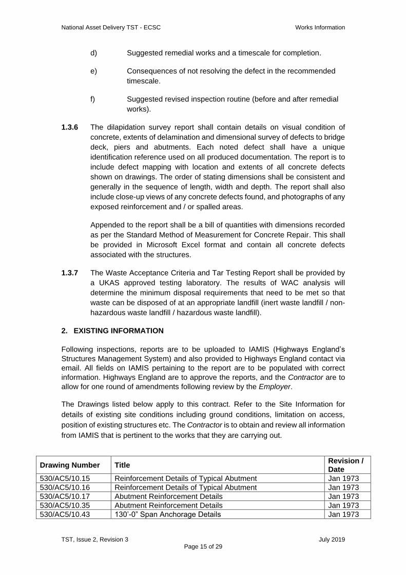
d) Suggested remedial works and a timescale for completion.
e) Consequences of not resolving the defect in the recommended
timescale.
f) Suggested revised inspection routine (before and after remedial
works).
1.3.6 The dilapidation survey report shall contain details on visual condition of
concrete, extents of delamination and dimensional survey of defects to bridge
deck, piers and abutments. Each noted defect shall have a unique
identification reference used on all produced documentation. The report is to
include defect mapping with location and extents of all concrete defects
shown on drawings. The order of stating dimensions shall be consistent and
generally in the sequence of length, width and depth. The report shall also
include close-up views of any concrete defects found, and photographs of any
exposed reinforcement and / or spalled areas.
Appended to the report shall be a bill of quantities with dimensions recorded
as per the Standard Method of Measurement for Concrete Repair. This shall
be provided in Microsoft Excel format and contain all concrete defects
associated with the structures.
1.3.7 The Waste Acceptance Criteria and Tar Testing Report shall be provided by
a UKAS approved testing laboratory. The results of WAC analysis will
determine the minimum disposal requirements that need to be met so that
waste can be disposed of at an appropriate landfill (inert waste landfill / non-
hazardous waste landfill / hazardous waste landfill).
2. EXISTING INFORMATION
Following inspections, reports are to be uploaded to IAMIS (Highways England’s
Structures Management System) and also provided to Highways England contact via
email. All fields on IAMIS pertaining to the report are to be populated with correct
information. Highways England are to approve the reports, and the Contractor are to
allow for one round of amendments following review by the Employer.
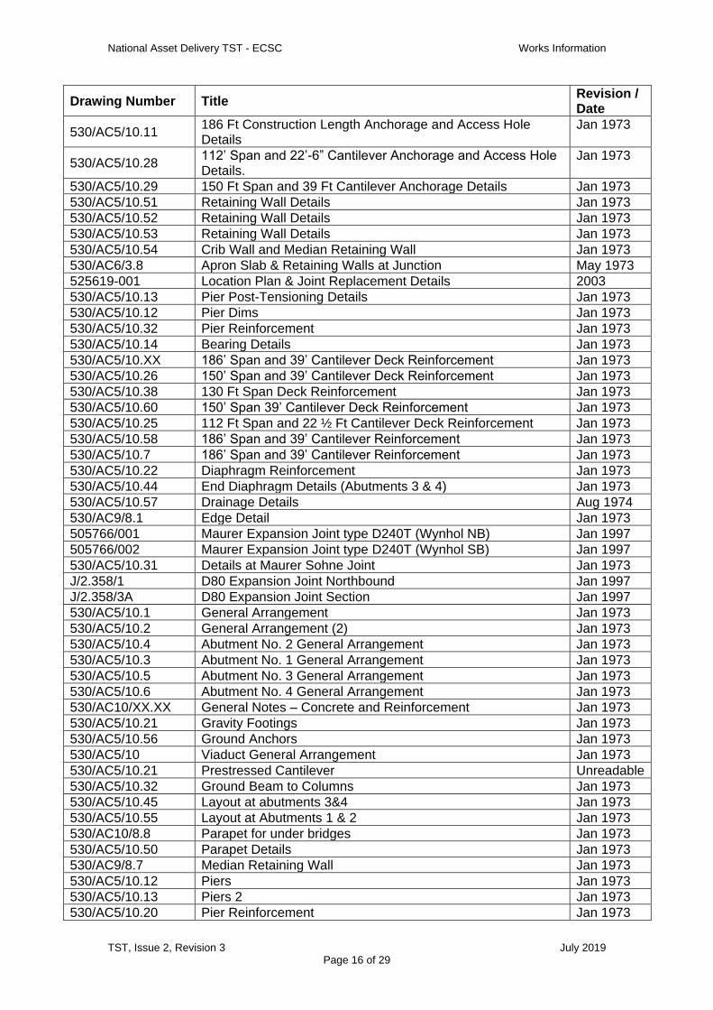
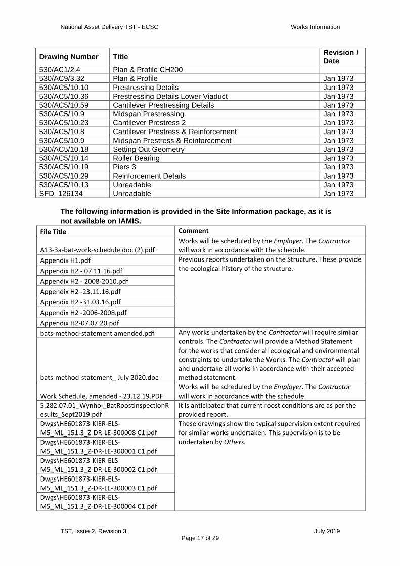
The Drawings listed below apply to this contract. Refer to the Site Information for
details of existing site conditions including ground conditions, limitation on access,
position of existing structures etc. The Contractor is to obtain and review all information
from IAMIS that is pertinent to the works that they are carrying out.
Drawing Number Title Revision / Date
530/AC5/10.15 Reinforcement Details of Typical Abutment Jan 1973
530/AC5/10.16 Reinforcement Details of Typical Abutment Jan 1973
530/AC5/10.17 Abutment Reinforcement Details Jan 1973
530/AC5/10.35 Abutment Reinforcement Details Jan 1973
530/AC5/10.43 130’-0” Span Anchorage Details Jan 1973
National Asset Delivery TST - ECSC Works Information
TST, Issue 2, Revision 3 July 2019
Page 16 of 29
Drawing Number Title Revision / Date
530/AC5/10.11 186 Ft Construction Length Anchorage and Access Hole Details
Jan 1973
530/AC5/10.28 112’ Span and 22’-6” Cantilever Anchorage and Access Hole Details.
Jan 1973
530/AC5/10.29 150 Ft Span and 39 Ft Cantilever Anchorage Details Jan 1973
530/AC5/10.51 Retaining Wall Details Jan 1973
530/AC5/10.52 Retaining Wall Details Jan 1973
530/AC5/10.53 Retaining Wall Details Jan 1973
530/AC5/10.54 Crib Wall and Median Retaining Wall Jan 1973
530/AC6/3.8 Apron Slab & Retaining Walls at Junction May 1973
525619-001 Location Plan & Joint Replacement Details 2003
530/AC5/10.13 Pier Post-Tensioning Details Jan 1973
530/AC5/10.12 Pier Dims Jan 1973
530/AC5/10.32 Pier Reinforcement Jan 1973
530/AC5/10.14 Bearing Details Jan 1973
530/AC5/10.XX 186’ Span and 39’ Cantilever Deck Reinforcement Jan 1973
530/AC5/10.26 150’ Span and 39’ Cantilever Deck Reinforcement Jan 1973
530/AC5/10.38 130 Ft Span Deck Reinforcement Jan 1973
530/AC5/10.60 150’ Span 39’ Cantilever Deck Reinforcement Jan 1973
530/AC5/10.25 112 Ft Span and 22 ½ Ft Cantilever Deck Reinforcement Jan 1973
530/AC5/10.58 186’ Span and 39’ Cantilever Reinforcement Jan 1973
530/AC5/10.7 186’ Span and 39’ Cantilever Reinforcement Jan 1973
530/AC5/10.22 Diaphragm Reinforcement Jan 1973
530/AC5/10.44 End Diaphragm Details (Abutments 3 & 4) Jan 1973
530/AC5/10.57 Drainage Details Aug 1974
530/AC9/8.1 Edge Detail Jan 1973
505766/001 Maurer Expansion Joint type D240T (Wynhol NB) Jan 1997
505766/002 Maurer Expansion Joint type D240T (Wynhol SB) Jan 1997
530/AC5/10.31 Details at Maurer Sohne Joint Jan 1973
J/2.358/1 D80 Expansion Joint Northbound Jan 1997
J/2.358/3A D80 Expansion Joint Section Jan 1997
530/AC5/10.1 General Arrangement Jan 1973
530/AC5/10.2 General Arrangement (2) Jan 1973
530/AC5/10.4 Abutment No. 2 General Arrangement Jan 1973
530/AC5/10.3 Abutment No. 1 General Arrangement Jan 1973
530/AC5/10.5 Abutment No. 3 General Arrangement Jan 1973
530/AC5/10.6 Abutment No. 4 General Arrangement Jan 1973
530/AC10/XX.XX General Notes – Concrete and Reinforcement Jan 1973
530/AC5/10.21 Gravity Footings Jan 1973
530/AC5/10.56 Ground Anchors Jan 1973
530/AC5/10 Viaduct General Arrangement Jan 1973
530/AC5/10.21 Prestressed Cantilever Unreadable
530/AC5/10.32 Ground Beam to Columns Jan 1973
530/AC5/10.45 Layout at abutments 3&4 Jan 1973
530/AC5/10.55 Layout at Abutments 1 & 2 Jan 1973
530/AC10/8.8 Parapet for under bridges Jan 1973
530/AC5/10.50 Parapet Details Jan 1973
530/AC9/8.7 Median Retaining Wall Jan 1973
530/AC5/10.12 Piers Jan 1973
530/AC5/10.13 Piers 2 Jan 1973
530/AC5/10.20 Pier Reinforcement Jan 1973
National Asset Delivery TST - ECSC Works Information
TST, Issue 2, Revision 3 July 2019
Page 17 of 29
Drawing Number Title Revision / Date
530/AC1/2.4 Plan & Profile CH200
530/AC9/3.32 Plan & Profile Jan 1973
530/AC5/10.10 Prestressing Details Jan 1973
530/AC5/10.36 Prestressing Details Lower Viaduct Jan 1973
530/AC5/10.59 Cantilever Prestressing Details Jan 1973
530/AC5/10.9 Midspan Prestressing Jan 1973
530/AC5/10.23 Cantilever Prestress 2 Jan 1973
530/AC5/10.8 Cantilever Prestress & Reinforcement Jan 1973
530/AC5/10.9 Midspan Prestress & Reinforcement Jan 1973
530/AC5/10.18 Setting Out Geometry Jan 1973
530/AC5/10.14 Roller Bearing Jan 1973
530/AC5/10.19 Piers 3 Jan 1973
530/AC5/10.29 Reinforcement Details Jan 1973
530/AC5/10.13 Unreadable Jan 1973
SFD_126134 Unreadable Jan 1973
The following information is provided in the Site Information package, as it is
not available on IAMIS.
File Title Comment
A13-3a-bat-work-schedule.doc (2).pdf Works will be scheduled by the Employer. The Contractor will work in accordance with the schedule.
Appendix H1.pdf Previous reports undertaken on the Structure. These provide the ecological history of the structure. Appendix H2 - 07.11.16.pdf
Appendix H2 - 2008-2010.pdf
Appendix H2 -23.11.16.pdf
Appendix H2 -31.03.16.pdf
Appendix H2 -2006-2008.pdf
Appendix H2-07.07.20.pdf
bats-method-statement amended.pdf Any works undertaken by the Contractor will require similar controls. The Contractor will provide a Method Statement for the works that consider all ecological and environmental constraints to undertake the Works. The Contractor will plan and undertake all works in accordance with their accepted method statement. bats-method-statement_ July 2020.doc
Work Schedule, amended - 23.12.19.PDF Works will be scheduled by the Employer. The Contractor will work in accordance with the schedule.
5.282.07.01_Wynhol_BatRoostInspectionResults_Sept2019.pdf
It is anticipated that current roost conditions are as per the provided report.
Dwgs\HE601873-KIER-ELS-M5_ML_151.3_Z-DR-LE-300008 C1.pdf
These drawings show the typical supervision extent required for similar works undertaken. This supervision is to be undertaken by Others. Dwgs\HE601873-KIER-ELS-
M5_ML_151.3_Z-DR-LE-300001 C1.pdf
Dwgs\HE601873-KIER-ELS-M5_ML_151.3_Z-DR-LE-300002 C1.pdf
Dwgs\HE601873-KIER-ELS-M5_ML_151.3_Z-DR-LE-300003 C1.pdf
Dwgs\HE601873-KIER-ELS-M5_ML_151.3_Z-DR-LE-300004 C1.pdf

National Asset Delivery TST - ECSC Works Information
TST, Issue 2, Revision 3 July 2019
Page 18 of 29
Dwgs\HE601873-KIER-ELS-M5_ML_151.3_Z-DR-LE-300005 C1.pdf
Dwgs\HE601873-KIER-ELS-M5_ML_151.3_Z-DR-LE-300006 C1.pdf
Dwgs\HE601873-KIER-ELS-M5_ML_151.3_Z-DR-LE-300007 C1.pdf
3. CONSTRAINTS ON HOW THE CONTRACTOR PROVIDES THE WORKS
3.1 General
3.1.1 The Contractor Provides the Works in such manner as to minimise the risk of
damage or disturbance to or destruction of third party property.
3.1.2 The Contractor complies with the constraints and meets with the requirements
outlined in Appendix 1.
3.1.3 The Contractor submits information detailing how the Contractor will provide
the Works to the Employer prior to the mobilisation. This information will include
any lifting plans, risk assessments, method statements, the Contractor’s staff
training information and any other relevant Health and Safety requirements.
3.2 Working hours & site specific constraints
3.2.1 Any required lane closures shall be deemed as taking place during night-time
hours. Other works shall be deemed to take place during daylight hours.
3.2.2 The Employer is to provide all traffic management. The Contractor must specify
what closures are required. This information is further detailed, alongside
associated activities, in Section 3.3 Table 1. Full road closure will not be
allowed under this contract.
3.2.3 The Traffic management is to be off peak lane closures. Night time working
windows shall be assumed as Monday to Friday between the hours of 23:00hrs
and 05:00 hrs (but will be subject to actual traffic conditions).
3.2.4 The post-tensioned tendons follow a hogging profile over piers and the edge of
the duct is anticipated to be within 100mm of the top of the deck slab at the
location of trial pits over piers. The total depth of the carriageway surfacing is
anticipated to be circa 40mm. Care must be taken when undertaking trial pitting
and related activities so as not to cause damage to the post-tensioned tendons.
3.2.5 Bats have been recorded roosting in the viaduct. These include the Lesser
Horseshoe Bat (Rhinolophus Hipposideros). This is a major colony with
upwards of 100 bats observed. A bat mitigation license will need to be obtained
from Natural England prior to works within the abutments. The Employer will
apply for this licence. The Contractor will implement any requirements of the
licence. It is anticipated that works will adopt a precautionary approach, be
National Asset Delivery TST - ECSC Works Information
TST, Issue 2, Revision 3 July 2019
Page 19 of 29
restricted to avoid maternal and hibernating seasons and specific working
hours with the following constraints:
3.2.5.1 Bats roost within abutment chambers and at joint locations. Plywood screens
will be placed over manholes which provide access into deck chambers to
avoid dust, light and noise from carrying into the deck chambers (where the
majority of bats roost).
3.2.5.2 All bat access points will be retained and works are limited to temporary
disturbance only.
3.2.5.3 Bats will be temporarily excluded from working areas during works, and access
will be reinstated after works have been completed. At all times there will be
entry/exit locations open into the deck chambers for bats whilst works is being
undertaken.
3.2.5.4 Temporary lighting will be required during the works. The generator for the
lighting will be located in an area to prevent a toxic build-up of fumes potentially
affecting the bats.
3.2.5.5 Refer to the Site Information for other bat mitigation measures that are typically
required on this site.
3.2.6 Access into the structure is via the abutments which have locked steel doors.
Keys will need to be obtained from Highways England prior to entry to
abutments. The Contractor will need to apply safe confined space working
methodology when working within the abutments.
3.2.7 Access to the land beneath the structures will require 3rd party consent (refer
to Survey Information Pack for land registry plans).
3.2.8 Pipes associated with the structure are predominantly asbestos cement
pipes. These pipes are not to be interfered with as part of these works. The
Contractor will be provided with all asbestos information prior to the Start
Date.
3.3 Recommended concurrence / phasing of works
3.3.1 It is recommended that works requiring traffic management are programmed
concurrently to effectively utilise road-space and access.
3.3.2 It is also recommended that works undertaken from ground level are
programmed concurrently to best utilise access to third party land.
3.3.3 The Contractor is to liaise with Highways England prior to programming works
to ensure that effective and efficient use of road space is maximised. The
Contractor should liaise with others to ensure that other works outside the

National Asset Delivery TST - ECSC Works Information
TST, Issue 2, Revision 3 July 2019
Page 20 of 29
scope of this TST are considered and if safe and appropriate, undertaken
within the same Traffic management.
3.3.4 Tasks set out within this works package alongside anticipated Traffic
management requirements and access requirements are set out in Table 1.
Traffic management shall be provided by the Contractor.
Activity Traffic Management Minimum Requirements
Special Access Requirements
Phasing of works
Trial Pitting activities Northbound Lanes 2 & 3, Southbound Hard shoulder and Lane 1
None Tranche A
Expansion Joint topside Inspection
All lanes, to be phased as per Section 3.2.2.
None Tranche A
Concrete testing to high level underbridge elements
Lane 1 and hard shoulder, both directions
Underbridge unit. Tranche A
Concrete dilapidation survey
Lane 1 and hard shoulder, both directions
Underbridge unit. Tranche A
Bearing Inspection to top Freyssinet hinges
Northbound Lanes 2 & 3, Southbound Hard shoulder and Lane 1
Underbridge unit. Tranche A
Concrete testing to low level elements
None 3rd Party Land. Tranche B
Bearing inspection to bottom Freyssinet hinges
None 3rd Party Land. Tranche B
Bearing Inspection to abutments
None 3rd Party Land. Confined space.
Tranche B
Expansion Joint underside Inspection
None 3rd Party Land. Confined space.
Tranche B
Table 1 – Recommended Phasing of Works
3.4 Health, Safety and Environment & Risk Management
Health and Safety requirements
3.4.1 In Providing the Works the Contractor meets the requirements of Annex 2 of
the supplementary constraints in relation to health and safety duties.
3.4.2 When implemented, the Contractor shall comply with the requirements of
Highways England’s safety passport scheme and ensure that all of his
employees, and any of his subcontractor’s, are registered in accordance with
the implementation of the scheme.
3.4.3 For details of the CDM duty holders, refer below:
Client – Highways England (Employer)

National Asset Delivery TST - ECSC Works Information
TST, Issue 2, Revision 3 July 2019
Page 21 of 29
Principal Contractor – To be appointed by the Employer. It is
anticipated that Traffic Management will be provided by the Principal
Contractor.
Contractor - Contractor
Principal Designer – Highways England (Employer)
Designer – Contractor
3.4.4 Before commencing the construction phase of the works, the Contractor
confirms to the Employer that adequate welfare facilities are in place. Where
the facilities detailed in section 5 are not deemed adequate, the Contractor
provides all necessary facilities to Provide the Works, and to comply with the
minimum requirements set out in HSE guidance document L153.
Environmental requirements
3.4.5 In Providing the Works the Contractor meets the requirements of Annex 2 of
the supplementary constraints in relation to environmental duties.
3.2.9 Highways England shall apply for a bat mitigation licence from Natural
England to enable works within the abutments.
Risk Management
3.4.6 The Contractor identifies, manages and mitigates risks in accordance with the
principles of ISO 31000.
3.4.7 The Contractor submits a risk register, which captures all risks associated
with the delivery of the works including those identified by the Employer, with
his tender and maintains it for the contract period.

National Asset Delivery TST - ECSC Works Information
TST, Issue 2, Revision 3 July 2019
Page 22 of 29
4. REQUIREMENTS FOR THE PROGRAMME
4.1 The Contractor submits programme to the Employer with his tender.
4.2 The Contractor Provides the Works taking into account the following programme
constraints:
(i) The starting date and completion date and any post site works, reporting
and review period;
(ii) The services and other things provided by Employer (see Section 5);
(iii) Recommended concurrency / phasing of works as outlined in Section 4.
Also other works outside the scope of this TST where it may be
appropriate to undertake works concurrently, i.e. utilising the same
Traffic management.
4.3 The programme should be in the form of an activity and time related bar chart,
produced as a result of a critical path analysis.
4.4 The programme should preferably be provided in either a PDF or MS Excel
format and cover the full contract period including post site activities. Activities
should be clearly defined and named and the programme should detail the
following:
(i) dates and times associated with the project, including the starting date,
completion date & Contractor’s planned completion, and any other dates
or times that will specifically impact the delivery of the project;
(ii) activities associated with delivering the site works and project outputs.
4.4.1 The Contractor updates the programme every 2 weeks. The Contractor
submits an updated programme to the Employer upon request.
Commission Date: As awarded
Mobilisation – 3 weeks from Commission Date
Draft Report Submission Date – 6 weeks from completion of site works
Review Period for Highways England – 2 weeks
Final Report Submission Date – 1 week from Draft Report Submission Date
Completion – 1 week following final report approval on IAMIS
National Asset Delivery TST - ECSC Works Information
TST, Issue 2, Revision 3 July 2019
Page 23 of 29
5 SERVICES AND OTHER THINGS PROVIDED BY THE EMPLOYER
5.1.1 The following temporary traffic management will be provided by the Employer
to allow the Contractor to Provide the Works:
(1) Traffic Management.
(2) Welfare facilities will be provided by the Employer.
(3) Bat Mitigation License to be obtained by the Employer. The
Contractor shall work in accordance with the Bat Mitigation License.
5.1.2 The other things that will be provided by the Employer are as follows:
(1) not used.
5.1.3 Things that will be provided by the Contractor are as follows:
(1) Specialist access equipment / machinery, plant and materials
required for trial pitting activities and all aspects of Works are to be
provided by the Contractor.
National Asset Delivery TST - ECSC Works Information
TST, Issue 2, Revision 3 July 2019
Page 24 of 29
6 SPECIFICATION FOR THE WORKS
The Contractor shall undertake the works in accordance with:
6.1.1 All works shall be undertaken in accordance with CS 450 Inspection of
Highway Structures.
6.1.2 All sampling and testing should be carried out by specialist testing firms or
laboratories approved by the UK’s Accreditation Service (UKAS) Body for
laboratory testing to ISO/IEC 17025.
6.1.3 The testing shall be undertaken in accordance with departmental Standard
CS 462 Repair and Management of Deteriorated Concrete Highway
Structures and CS 464 Non-destructive testing of highways structures.
6.1.4 All concrete removed from the structure shall be reinstated using a suitable
high strength, non-shrink, quick setting, proprietary repair mortar complying
with BS EN 1504-3:2005 Structural and non-structural repair and placed in
accordance with BS EN 1504-10:2017 Site application of products and
systems and quality control of the works.
6.1.5 Electromagnetic cover meter surveys shall be undertaken using the method
described in BS 1881-204:1988 Testing concrete. Recommendations on the
use of electromagnetic cover meters. The information to be included in the
testing report shall be in accordance with BS 1881-204:1988 Clause 10.
6.1.6 The procedure for measuring the electrode potential of steel reinforcement
and interpretation criteria shall be in accordance with TRL AG9 The Half-Cell
Potential Method of Locating Corroding Reinforcement in Concrete
Structures, ASTM C876-15 Standard Method for Half-cell Potentials of
Uncoated Reinforcing Steel in Concrete, and in accordance with the
recommendations of CS TR60 Electrochemical Tests for Reinforcement
Corrosion and CS TG2 Guide to testing and monitoring the durability of
concrete structures.
6.1.7 Measuring electrical resistivity of concrete shall be in accordance with the
procedure given in CS TR60 Electrochemical Tests for Reinforcement
Corrosion. Resistivity interpretation criteria shall be aligned with Table 5 of
Digest 434 Corrosion of reinforcement in concrete: Electrochemical
Monitoring
6.1.8 The depth of carbonation shall be determined in accordance with BS EN
14630 Products and systems for the protection and repair of concrete
structures. Test methods. Determination of carbonation depth in hardened
concrete by the phenolphthalein method.
6.1.9 Analysis of dust samples to determine chloride content, sulfate content and
alkali content shall be carried out through a UKAS Accredited laboratory in
National Asset Delivery TST - ECSC Works Information
TST, Issue 2, Revision 3 July 2019
Page 25 of 29
accordance with BS 1881-124, Testing Concrete - Part 124: Methods for
Analysis of Hardened Concrete. No chemical tests shall be undertaken on
site with the exception of carbonation testing.
6.1.10 Sampling for measuring chloride and cement content shall be undertaken
using the procedures described in BRE IP 21/86 Determination of the chloride
and cement contents of hardened concrete and in accordance with the
recommendations of CS TR60 Electrochemical Tests for Reinforcement
Corrosion and CS TR32 Analysis of hardened concrete: A guide to tests,
procedures and interpretation of results. Interpretation of results shall be in
accordance with CS 462 Repair and management of deteriorated concrete
structures.
6.1.11 The tensile pull-off method for adhesion testing of the waterproofing shall be
undertaken in alignment ASTM D7234-19 Standard Test Method for Pull-Off
Adhesion Strength of Coatings on Concrete Using Portable Adhesion Testers.
Waterproofing to be reinstated with suitably compatible material and have
BBA HAPAS Roads and Bridges Certificate.
6.1.12 Waterproofing shall be reinstated in accordance with the method statement
agreed with the Certification Body, and in accordance with CD 358
Waterproofing and surfacing of concrete bridge decks Revision 1. The
minimum adhesion and bond strength of the waterproofing system shall be
compliant with Table 6.4 of CD 358.
6.1.13 Excavation, laying and compaction of materials (trial pitting) shall be
undertaken in accordance with DfT Specification for the reinstatement of
openings in Highways, Fourth Edition S10. Simplified guidance can be sought
in DfT Practical Guide to Street Works. The minimum, nominal and maximum
compacted lift thickness is to be in alignment with Annex 8 Table A2.2 of DfT
Practical Guide to Streetworks.
6.1.14 Tar testing and interpretation of results shall be undertaken in accordance
with County Surveyors Society Guidance note ‘Road Materials Containing
Tar’.
6.1.15 Waste shall be classified and tested to specific Waste Acceptance Criteria
prior to disposal, in accordance with Hazardous Waste Regulations 2005,
Landfill Regulations 2005 and Waste Framework Directive 2008/98/EC.
Waste Acceptance Criteria testing shall be undertaken in accordance with in
accordance with BS EN 12457-2:2002 Characterisation of waste - Leaching -
National Asset Delivery TST - ECSC Works Information
TST, Issue 2, Revision 3 July 2019
Page 26 of 29
Compliance test for leaching of granular waste materials and sludges; and the
Landfill Regulations [9] by a UKAS accredited laboratory.
6.1.16 Bearing inspections are to be undertaken and reported on in accordance with
BS EN 1337-10:2003 Structural Bearings – Inspection and Maintenance.
6.1.17 The requirements of CD 357 Bridge Expansion Joints Are to be adhered to
with respect to inspection of expansion joints. Expansion joints should also be
inspected in alignment with TfL Inspection guidance for bridge deck
expansion joints.
6.1.18 The Concrete Dilapidation survey is to comprise an inspection of the general
condition of the concrete to all concrete elements, within touching distance.
Measurements obtained from the Concrete Dilapidation survey are to be
obtained using the Concrete Repair Association Standard Method of
Measurement for Concrete Repair.
National Asset Delivery TST - ECSC Works Information
TST, Issue 2, Revision 3 July 2019
Page 27 of 29
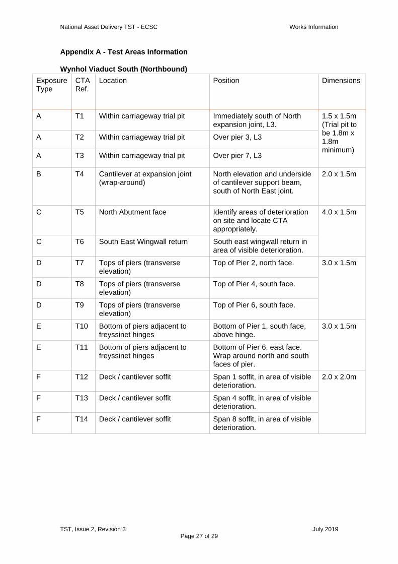
Appendix A - Test Areas Information
Wynhol Viaduct South (Northbound)
Exposure Type
CTA Ref.
Location Position Dimensions
A T1 Within carriageway trial pit Immediately south of North expansion joint, L3.
1.5 x 1.5m (Trial pit to be 1.8m x 1.8m minimum)
A T2 Within carriageway trial pit Over pier 3, L3
A T3 Within carriageway trial pit Over pier 7, L3
B T4 Cantilever at expansion joint (wrap-around)
North elevation and underside of cantilever support beam, south of North East joint.
2.0 x 1.5m
C T5 North Abutment face Identify areas of deterioration on site and locate CTA appropriately.
4.0 x 1.5m
C T6 South East Wingwall return South east wingwall return in area of visible deterioration.
D T7 Tops of piers (transverse elevation)
Top of Pier 2, north face. 3.0 x 1.5m
D T8 Tops of piers (transverse elevation)
Top of Pier 4, south face.
D T9 Tops of piers (transverse elevation)
Top of Pier 6, south face.
E T10 Bottom of piers adjacent to freyssinet hinges
Bottom of Pier 1, south face, above hinge.
3.0 x 1.5m
E T11 Bottom of piers adjacent to freyssinet hinges
Bottom of Pier 6, east face. Wrap around north and south faces of pier.
F T12 Deck / cantilever soffit Span 1 soffit, in area of visible deterioration.
2.0 x 2.0m
F T13 Deck / cantilever soffit Span 4 soffit, in area of visible deterioration.
F T14 Deck / cantilever soffit Span 8 soffit, in area of visible deterioration.
National Asset Delivery TST - ECSC Works Information
TST, Issue 2, Revision 3 July 2019
Page 28 of 29
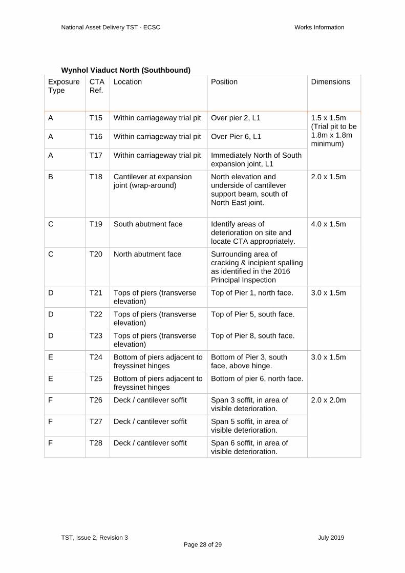
Wynhol Viaduct North (Southbound)
Exposure Type
CTA Ref.
Location Position Dimensions
A T15 Within carriageway trial pit Over pier 2, L1 1.5 x 1.5m (Trial pit to be 1.8m x 1.8m minimum)
A T16 Within carriageway trial pit Over Pier 6, L1
A T17 Within carriageway trial pit Immediately North of South expansion joint, L1
B T18 Cantilever at expansion joint (wrap-around)
North elevation and underside of cantilever support beam, south of North East joint.
2.0 x 1.5m
C T19 South abutment face Identify areas of deterioration on site and locate CTA appropriately.
4.0 x 1.5m
C T20 North abutment face Surrounding area of cracking & incipient spalling as identified in the 2016 Principal Inspection
D T21 Tops of piers (transverse elevation)
Top of Pier 1, north face. 3.0 x 1.5m
D T22 Tops of piers (transverse elevation)
Top of Pier 5, south face.
D T23 Tops of piers (transverse elevation)
Top of Pier 8, south face.
E T24 Bottom of piers adjacent to freyssinet hinges
Bottom of Pier 3, south face, above hinge.
3.0 x 1.5m
E T25 Bottom of piers adjacent to freyssinet hinges
Bottom of pier 6, north face.
F T26 Deck / cantilever soffit Span 3 soffit, in area of visible deterioration.
2.0 x 2.0m
F T27 Deck / cantilever soffit Span 5 soffit, in area of visible deterioration.
F T28 Deck / cantilever soffit Span 6 soffit, in area of visible deterioration.

National Asset Delivery TST - ECSC Works Information
TST, Issue 2, Revision 3 July 2019
Page 29 of 29
Appendix B - Test areas location plan


