* Corresponding author: [email protected]
New Ashton Arch - functional assessment of direct and indirect construction costs and evaluation of service life with respect to flooding risk
Philip Ronné1*, Abe Newmark1, Nadri du Toit1, and Heinrich van Wijk1
1AECOM SA (Pty) Ltd, Bridge Engineering, Cape Town, South Africa
Abstract. The bridge crossing the Cogmanskloof River in the town of Ashton, South Africa, had a
history of over-topping due to severe flood events. The poor flood resilience of the bridge was
aggravated by the generally hydraulically inefficient openings, the number of substructure supports
in the river course, and a high debris load during flooding. The strategically important tourist route
had to be closed, while localized flood damage repairs were undertaken, with resultant adverse
effects on the local economy. As part of a road safety improvement project between the towns of
Ashton and Montagu, improvement of the flooding resistance at the Ashton river bridge was
required. This paper documents the functional evaluation of economic- and technical-assessments of
the flooding risks for the existing retro-fitted bridge. A new tied-arch bridge was the selected
structural form of the replacement structure – based on the assessment of the key service life and
constructability criteria. The structural form of the Ashton Arch paid careful regard to the scenic
location and historic character of the previous multiple arch bridge form.
1 Project background
The project, conducted under the auspices of Western
Cape Provincial Government’s Department of Transport
and Public Works: Roads Infrastructure Branch,
involved the reconstruction of parts of Trunk Road 31
Sections 2 and 3, between the Western Cape towns of
Ashton and Montagu, South Africa. This 13km long road
is also the start of the strategically important tourist
‘Route 62’. Typically about 7000 vehicles travel through
Ashton and 3600 vehicles through Cogmanskloof Pass
and Montagu every day.
A particular focal point of the project is the historic
Cogmanskloof Pass. The 6,5km long pass stretches
through a majestic landscape of towering rock
formations and a colourful pastoral patchwork. Renamed
after the popular Cape Colonial Secretary John Montagu,
the town's original name was Cogmanskloof, from which
the pass took its name. ‘Cogmanskloof’ comes from the
Cogmans Khoi chiefdom that lived in the area in the
early eighteenth century.
This section of Trunk Road 31/2, currently a single
surfaced carriageway with gravel shoulders, was
constructed as a gravel road and completed in 1877, and
first surfaced in 1931. The last resurfacing was
undertaken in 1985. This part of the route has, for some
time, been in need of upgrading and rehabilitation due to
marked deterioration of the road surface, traffic capacity
constraints, and road safety requirements (due to
substandard width and geometric alignment in some
locations). Other major considerations were the flood
capacity and erosion resistance of the roadway and river
bridges.
The Cogmanskloof River flows adjacent to the route
for a significant distance and crosses the roadway at four
discrete locations by means of existing bridge structures.
These bridges do not currently have adequate hydraulic
capacity. The greater Ashton-Montagu region, and
Cogmanskloof Pass in particular, experienced substantial
flood damage that resulted in multiple road closures and
significant operational disruptions, with adverse impacts
on the local economy. The largest of these recent floods
occurred in March 2003 (Fig.1), while significant
although less severe flooding also occurred during April
2005, July to August 2006, November 2008 and June
2012. The high debris load in the Cogmanskloof River
exacerbates the effects of flooding at the existing short
span bridges. Generally these bridges have wide solid
wall type piers, orientated at unfavourable skew angles
relative to the sometimes variable flow direction. This
has resulted in severe debris blocking of the hydraulic
opening (Fig. 2) and resulting overtopping, particularly
at the river bridge in Ashton.
MATEC Web of Conferences 199, 06003 (2018) https://doi.org/10.1051/matecconf/201819906003ICCRRR 2018
© The Authors, published by EDP Sciences. This is an open access article distributed under the terms of the Creative Commons Attribution License 4.0
(http://creativecommons.org/licenses/by/4.0/).

Fig. 1. Overtopping of the existing Ashton river bridge during
the 2003 flood.
Fig. 2. Debris accumulation at Ashton river bridge during the
2003 flood.
2 End of functional life assessment of existing arch bridge
The original bridge over the Cogmanskloof River in
Ashton, was constructed in the 1930’s. The original
structural form was a five span, earth-filled arch type
superstructure, allowing single lane vehicular traffic.
The substructure consisted of wall type piers and
abutments, with an angle of skew of 50 degrees with the
river.
In 1950 a substantial structural retro-fitment was
undertaken, modifying the superstructure to a cast in situ
beam and slab configuration that maintained portions of
the arch superstructure (Fig. 3 & 4), including the arch-
profile with related hydraulic opening configuration. The
retro-fitment allowed two-way single carriageway
vehicular traffic of 3,35m traffic lanes and 1,8m
pedestrian sidewalks. The 3m wide transverse
cantilevers are supported from the arch-profiled
longitudinal beams. The retro-fitted road was typically
between 5m and 8m above the natural ground level,
approximately representing the 1:50 floodline.
Fig. 3. View along deck of existing Ashton bridge.
Fig. 4. View of deck underside of existing Ashton bridge.
The client’s brief involved improvement, to
acceptable modern standards, of the flood resilience and
overall safety of the road. Technical proposals were
required to address the risk of frequent- and severe-
flooding at the Ashton river bridge location.
1950 Bridge widening consisting of cast in situ
concrete beam and slab
system spanning existing structure
Deck soffit of original
arch bridge
MATEC Web of Conferences 199, 06003 (2018) https://doi.org/10.1051/matecconf/201819906003ICCRRR 2018
2

2.1 Physical and economic considerations of existing Ashton Bridge
An economic analysis evaluated the ‘do nothing’ option,
where the micro-economic impact of closing the road
during regular incidence of flooding and accepting
substantial reduction in the road width over the existing
Ashton river bridge was assessed. The most significant
costs included in the economic model were flood
damage cost, accident cost, lane merge delays, traffic
delays, road closure during flooding, and maintenance
costs. Using an appropriate discount rate over a 50 year
forecast period, the modelled costs for the ‘do nothing’
option approached, but did not exceed the estimated
replacement cost for the bridge. The modelled costs
excluded macro-economic factors such as the strategic
value of the road, the broader scope of the road
reconstruction project, and other macro-economic dis-
benefits and adverse consequences of flooding that
further motivate the replacement of the Ashton bridge.
2.2 Bridge replacement considerations
Five bridge replacement options were investigated to
assess the most suitable structural form and ensure that
the final solution appropriately satisfied the client brief
and the related economic, functional and constructability
requirements. The key technical boundary conditions
included:
• The road had to remain open to traffic throughout the
construction period with limited disruption of the route,
• The hydraulic capacity and efficiency of the bridge
required substantial improvement, to address current
shortcomings and comply with applicable modern
criteria for this route classification,
• The design needed to accommodate flood risks during
the construction phase and service life,
• Improvements to the geometric alignment were
required to accommodate a wider (four lane) road cross
section and provide acceptable flood free-board
clearances,
• Minimize the effects on adjacent properties and road
intersections in Ashton, and
• Construction methods and constructability.
Three structural configurations were considered,
namely a multiple span continuous voided slab deck,
multiple span pre-cast beams and a single span tied arch
bridge. The construction methods for the first two
options were evaluated in terms of half-width
construction or by the provision of an adjacent low-level
bypass river crossing during construction.
The optional half-width construction strategy
would result in technical difficulties and associated
additional cost to stabilize the partial existing deck
during construction in both the first two options.
The provision of a bypass in the river would result
in a significant additional construction, traffic safety and
operational risks. In addition, achieving the necessary
flood resistance of the by-pass during construction to an
acceptable standard would imply a significant additional
cost premium and substantially increased flood risk to
adjacent property in the urban environment.
The proposed transversely launched construction
method of the tied arch option allows the new bridge to
be used as a traffic deviation in its temporary position,
while the existing bridge is demolished. After the
construction of the new permanent bridge substructure
and associated roadworks (Fig. 5), the tied arch bridge
will be launched horizontally into its final position.
Thereafter all the temporary works will be removed from
the river course.
Fig. 5. Temporary position, in plan, of the new Ashton Arch
prior to transverse launching.
2.2.1. Voided slab deck
A voided slab deck option would require construction of
the new deck, approximately 1,5m deep, at a
significantly higher elevation (+3,0m above the existing
bridge) to achieve the required hydraulic capacity. The
presence of piers in the water course, significantly wider
than the current sub-structure, would result in additional
debris accumulation risk, as well as local scour effects.
Higher approach fills (in comparison to the final option)
would be required with significant additional
construction costs at nearby existing intersections and
related impacts on existing properties.
The resulting new deck would have a 2,15m
horizontal eccentricity off the current centreline (Fig. 6)
with additional adverse effects on adjacent properties.
This bridge replacement option, using half width
construction method, had the lowest total construction
and indirect cost.
Fig. 6. Voided slab deck option.
TRANSVERSE LAUNCH DIRECTION
MATEC Web of Conferences 199, 06003 (2018) https://doi.org/10.1051/matecconf/201819906003ICCRRR 2018
3

2.2.2 Precast beam and cast in place slab deck
The precast beam and cast in place slab deck option
would require construction of the new deck,
approximately 1,5m deep, at a significantly higher level
(+3,0m above the existing bridge) to achieve the
required hydraulic capacity. The presence of very wide
piers in the water course, which are significantly wider
than the requirement for the voided slab sub-structure
(Fig. 7), would result in the highest debris accumulation
risk, as well as local scour effects, of all the alternatives
considered. Much higher approach fills would be
required with significant additional construction costs at
nearby existing intersections.
This bridge replacement option had a total cost
premium of 25% higher than the lowest cost option.
Fig. 7. Precast beam and cast in place slab deck option.
2.2.3 Tied arch, launched transversely into final position (preferred option)
The tied arch bridge, with deck depth of 1,0m, allowed
the construction of the new deck at a lower level (+2,5m
above the existing bridge) than the preceding options to
achieve the required hydraulic capacity and free board.
No piers are required in the river course, substantially
alleviating the risk of debris accumulation and backwater
effects. Local scour effects are also significantly
reduced.
A second economic analysis, that incorporated the
estimated construction costs for the preceding bridge
replacement options and indirect costs associated with
the posed solution, clearly demonstrated that the
preferred bridge replacement solution was the
transversely launched, tied-arch bridge.
The bridge option had a total cost premium of 10%
higher than the lowest cost (but high risk) option, but
was showed a 15% saving relative to other plausible
construction options.
This bridge replacement option was the sole
technical solution that fully satisfied all the key service
life and constructability criteria, as summarized
schematically in Table 1, while at the same time
providing significant risk-alleviating benefits and a very
elegant solution.
Table 1. Key bridge replacement considerations.
3 General details of the new Ashton Arch.
The new Ashton Arch has a tied-arch structural form,
with a single span of 110m (Fig. 9). Durable, high
strength 50 MPa concrete was specified for the arch rib
and tie-beam members, while the remainder of the
bridge structural components utilize 40 MPa concrete.
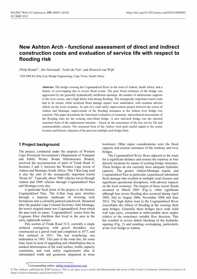
The typical cross-section of the Ashton Arch
provides for four 3,4m traffic lanes and two 2,4m
sidewalks. The overall height of the bridge is
approximately 23m from deck soffit to top of the arch.
The twin parallel arch ribs are connected via 15,5m
wishbone beams that provide lateral stability to the
bridge. Post-tensioned tie-beams complete the arch,
along with post-tensioned longitudinal and transverse
beams supporting the integral deck slab, resulting in a
coffered deck arrangement (Fig. 8). Each arch has
twenty-four fully-locked coil-type hangers that connect
the arch rib and tie-beam by fork sockets, via a pin
connection, to locally cast, engineering-grade, metal
anchor plates. The anchor plates are, in turn connected to
the concrete structure via high strength threaded, stress
bars.
Construction of the Ashton Arch is currently well
underway, with completion of the arch superstructure (in
its temporary position) scheduled for late 2018, and
completion of the overall project scheduled towards the
second half of 2019.
MATEC Web of Conferences 199, 06003 (2018) https://doi.org/10.1051/matecconf/201819906003ICCRRR 2018
4
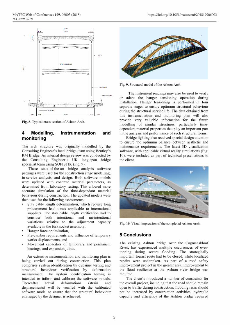
Fig. 8. Typical cross-section of Ashton Arch.
4 Modelling, instrumentation and monitoring
The arch structure was originally modelled by the
Consulting Engineer’s local bridge team using Bentley’s
RM Bridge. An internal design review was conducted by
the Consulting Engineer’s UK long-span bridge
specialist team using SOFISTIK (Fig. 9).
These state-of-the-art bridge analysis software
packages were used for the construction stage modelling,
in-service analysis, and design. Both software models
were updated with concrete material parameters, as
determined from laboratory testing. This allowed more
accurate simulation of the time-dependant material
behaviour during construction. The updated models were
then used for the following assessments:
• Stay cable length determination, which require long
procurement lead times applicable to international
suppliers. The stay cable length verification had to
consider both intentional and un-intentional
variations, relative to the adjustment capacity
available in the fork socket assembly,
• Hanger force optimisation,
• Pre-camber requirements and influence of temporary
works displacements, and
• Movement capacities of temporary and permanent
bearings, and expansion joints.
An extensive instrumentation and monitoring plan is
being carried out during construction. This plan
comprises system identification by dynamic testing and
structural behaviour verification by deformation
measurement. The system identification testing is
intended to inform and calibrate the software models.
Thereafter actual deformations (strain and
displacements) will be verified with the calibrated
software model to ensure that the structural behaviour
envisaged by the designer is achieved.
Fig. 9. Structural model of the Ashton Arch.
The instrument readings may also be used to verify
or adapt the hanger tensioning operation during
installation. Hanger tensioning is performed in four
separate stages to ensure optimum structural behaviour
during the structural service life. The data obtained from
this instrumentation and monitoring plan will also
provide very valuable information for the future
modelling of similar structures, particularly time-
dependent material properties that play an important part
in the analysis and performance of such structural forms.
Bridge lighting also received special design attention
to ensure the optimum balance between aesthetic and
maintenance requirements. The latest 3D visualization
software, with applicable virtual reality simulations (Fig.
10), were included as part of technical presentations to
the client.
Fig. 10. Visual impression of the completed Ashton Arch.
5 Conclusions
The existing Ashton bridge over the Cogmanskloof
River, has experienced multiple occurrences of over-
topping during severe flooding. The strategically
important tourist route had to be closed, while localized
repairs were undertaken. As part of a road safety
improvement project in the greater area, improvement to
the flood resilience at the Ashton river bridge was
required.
The client’s introduced a number of constraints for
the overall project, including that the road should remain
open to traffic during construction, flooding risks should
not be increased by construction activities, hydraulic
capacity and efficiency of the Ashton bridge required
MATEC Web of Conferences 199, 06003 (2018) https://doi.org/10.1051/matecconf/201819906003ICCRRR 2018
5

improvement, geometric improvements resulting from
road safety and flooding improvements should be
considered, and the construction methods and
constructability should be carefully assessed with
technical proposals.
Detailed economic analysis clearly demonstrated
that the preferred bridge replacement solution was the
transversely launched, tied-arch bridge, based on
estimated construction costs and indirect costs. The
transversely launched, tied arch bridge replacement
option was the sole technical solution that fully satisfied
all the client’s- and constructability- criteria. This bridge
option had a total cost premium of 10% higher than the
lowest cost option (with unacceptably high construction
risk), but demonstrated a 15% saving relative to other
plausible construction options.
The transversely launched construction method
allows the new bridge to be used as a traffic deviation in
its temporary position, while the existing bridge is
demolished. After the construction of the new permanent
bridge substructure and associated roadworks, the tied
arch bridge will be launched horizontally into its final
position. Thereafter all the temporary works will be
removed from the river course
A detailed record of the instrumentation and
monitoring with related analysis will be the subject of a
follow-up paper on completion of the structure.
This paper is published with the kind permission of the
Western Cape Provincial Government’s Department of
Transport and Public Works: Roads Infrastructure Branch.
Basil Read was the main contractor, the bridge design engineer
was Mr Edward Smuts, and AECOM SA (Pty) Ltd performed
the roles of Design- and Contract-Engineer for the Contract
C818.
MATEC Web of Conferences 199, 06003 (2018) https://doi.org/10.1051/matecconf/201819906003ICCRRR 2018
6


