Specifications & design are subject to change without prior notice. Please visit CTC Union website for more details. 6-1ww w.ct cu.com sales@ ct cu.com
6
Industrial Serial Fiber Converter Industrial Serial Fiber C
onverter
IFC-Serial-PRO
IFC-FDC-PRO
PROFIBUS to Fiber Converter
PROFIBUS to Daisy Chain Fiber Converter
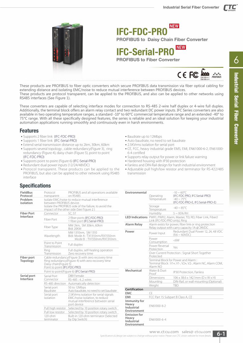
These products are PROFIBUS to fiber optic converters which secure PROFIBUS data transmission via fiber optical cabling for extending distance and isolating EMC/noise to reduce mutual interference between PROFIBUS devices.These products are protocol transparent, can be applied to the PROFIBUS, and also can be applied to other networks using RS485 interfaces (See Figure 1).
These converters are capable of selecting interface modes for connection to RS-485 2-wire half duplex or 4-wire full duplex. Additionally, the terminal block offers an alarm relay contact and two redundant DC power inputs. IFC Series converters are also available in two operating temperature ranges, a standard -10° to 60°C commercial temperature range and an extended -40° to 75°C range. With all these specifically designed features, the series is reliable and an ideal solution for keeping your industrial automation applications running smoothly and continuously even in harsh environments.
Features ▪ Supports 2 fiber link (IFC-FDC-PRO) ▪ Supports 1 fiber link (IFC-Serial-PRO) ▪ Extend serial transmission distance up to 2km, 30km, 60km ▪ Supports several topology , cable redundancy(Figure 3), ring redundancy (Figure 4), daisy chain (Figure 5), point to point (IFC-FDC-PRO) ▪ Supports point to point (Figure 6) (IFC-Serial-PRO) ▪ Redundant dual power inputs (12/24/48VDC) ▪ Protocol transparent. These products can be applied to the PROFIBUS, but also can be applied to other network using RS485 interface
▪ Baudrate up to 12Mbps ▪ Auto baudrate, no need to set baudrate ▪ 2.5KVrms isolation for serial port ▪ CE, FCC, heavy industrial grade EMS, EMI, EN61000-6-2, EN61000-6-4 certified ▪ Supports relay output for power or link failure warning ▪ Hardened housing with IP30 protection ▪ Fanless and DIN-Rail design for harsh industrial environment ▪ Adjustable pull high/low resistor and terminator for RS-422/485 transmission
SpecificationsEnvironmental
Operating Temperature
-10 ~ 60°C(IFC-FDC-PRO, IFC-Serial-PRO)-40 ~ 75°C(IFC-FDC-PRO-E, IFC-Serial-PRO-E)
Storage Temperature -40 ~ 85°C
Humidity 5 ~ 95% RHLED Indications PWR1, PWR2, Alarm, Master, TD, RD, Fiber Link, Fiber2
Link (IFC-FDC-PRO only), RingAlarm Relay Alarm exists for power, fiber link or ring protection
Relay output with carry capacity 1A @ 24VDCPower Power Input Redundant Dual Power 12, 24, 48 VDC
(9.6 ~ 60VDC)Power Consumption <6W
Power Reversal Protection Yes
Over Current Protection : Signal Short Together ProtectedTerminal Block for Power and Alarm : Terminal Block : V1+, V1-, V2+, V2-, Alarm NC, Alarm COM, Alarm NO
Mechanical Water & Dust Proof IP30 Protection, Fanless
Dimensions 106 x 38.6 x 142.1mm (D x W x H)Mounting DIN-Rail, or wall mounting (Optional) Weight TBD
CertificationEMC CEEMI FCC Part 15 Subpart B Class A, CEImmunity for Heavy Industrial Environment
EN61000-6-2
Emission for Heavy Industrial Environment
EN61000-6-4
FieldBus Protocol
Protocoltransparent
PROFIBUS and all operations available on RS485
Problem isolation
Isolate EMC/noise to reduce mutual interference between PROFIBUS device. Isolate the PROFIBUS side of the failure, to avoid the impact of the other side (See Figure 2 )
Fiber Port Interface
Connector SC, ST
Fiber Port 2 fiber ports (IFC-FDC-PRO)1 fiber port (IFC-Serial-PRO)
Fiber Type MM 2km, SM 30km, 60km Bidi 20KM
WavelengthMM 1310nm, SM 1310Bidi: Mode A : TX1310nm/RX1550nm Mode B : TX1550nm/RX1310nm
Point to Point Transmission Full duplex
Ring Transmission
Full duplex, self-healing operation Zero recovery time
Fiber port Topology
Cable redundancy(Figure 3) with zero recovery time Ring redundancy(Figure 4) with zero recovery time Daisy chain(Figure 5) Point to point (IFC-FDC-PRO)Point to point(Figure 6) (IFC-Serial-PRO)
Serial port Interface
Serial Port Connector
DB9 FemaleRS-485 : 4, 2 wires
RS-485 direction Automatically detectionSerial port Baudrate
50 to 12MbpsAuto baudrate, no need to set baudrate
Serial port isolation
2.5KVrms isolation for serial signalsEMC/noise isolation, to reduce mutual interference between serial port device
Pull high resistor Selected by 10 position rotary switchPull low resistor Selected by 10 position rotary switch120 ohm terminator
Built-in 120 ohm terminator (Selected by Dip Switch)
PROFIBUSEN61000-6-2EN61000-6-4
NEWNEW
NEWNEW
Specifications & design are subject to change without prior notice. Please visit CTC Union website for more details. 6-2 ww w.ct cu.com sales@ ct cu.com
Industrial Serial Fiber Converter
EMS(Electromagnetic Susceptibility) Protection Level
EN61000-4-2 ESD Level 3EN61000-4-3 RS Level 3EN61000-4-4 EFT Level 3EN61000-4-5 Surge Level 3 EN61000-4-6 CS Level 3
Free Fall IEC 60068-2-32Vibration IEC 60068-2-6Shock IEC 60068-2-27Green RoHSMTBF TBD
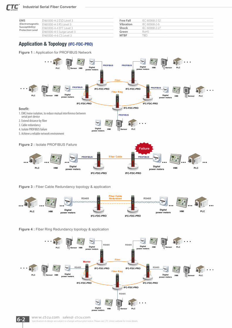
Application & Topology (IFC-FDC-PRO)
Figure 1 : Application for PROFIBUS Network
Figure 2 : Isolate PROFIBUS Failure
Fiber Ring
Fiber
Digitalpower meters
SensorHMI
5F000412
5F000412
PLC
Digitalpower meters
SensorHMI PLC
Digitalpower meters
Digitalpower meters
Sensor
Sensor
HMI
HMI
PLC
PLC
Digitalpower meters
Sensor HMIPLC
5F000412
5F000412
5F000412
PROFIBUS
PROFIBUS
PROFIBUS
PROFIBUS
PROFIBUS
IFC-FDC-PRO
IFC-FDC-PRO
IFC-FDC-PRO
IFC-FDC-PROIFC-FDC-PRO
Benefit:1. EMC/noise isolation, to reduce mutual interference between serial port device2. Extend distance by fiber3. Cable redundancy 4. Isolate PROFIBUS failure 5. Achieve a reliable network environment
5F000412
Fiber Cable
Digitalpower meters HMI PLCHMIPLC
PROFIBUSPROFIBUS
IFC-FDC-PROIFC-FDC-PRO
5F000412
Digitalpower meters
Failure
5F000412
IFC-FDC-PRO IFC-FDC-PRO
Fiber CableRedundant
Digitalpower meters HMI PLC
RS485RS485
HMIPLC
5F000412
Digitalpower meters
Figure 3 : Fiber Cable Redundancy topology & application
Fiber Ring
FiberMaster
Digitalpower meters
SensorHMI
5F000412
5F000412
PLC
Digitalpower meters
SensorHMI PLCDigital
power metersSensor HMIPLC
Digitalpower meters
Sensor HMIPLC
5F0004125F
000412
RS485
RS485
RS485
RS485
RS485 IFC-FDC-PRO IFC-FDC-PRO
IFC-FDC-PROIFC-FDC-PRO
Digitalpower meters
SensorHMI PLC
5F000412
IFC-FDC-PRO
Figure 4 : Fiber Ring Redundancy topology & application
Specifications & design are subject to change without prior notice. Please visit CTC Union website for more details. 6-3ww w.ct cu.com sales@ ct cu.com
6
Industrial Serial Fiber Converter Industrial Serial Fiber Converter Industrial Serial Fiber C
onverter
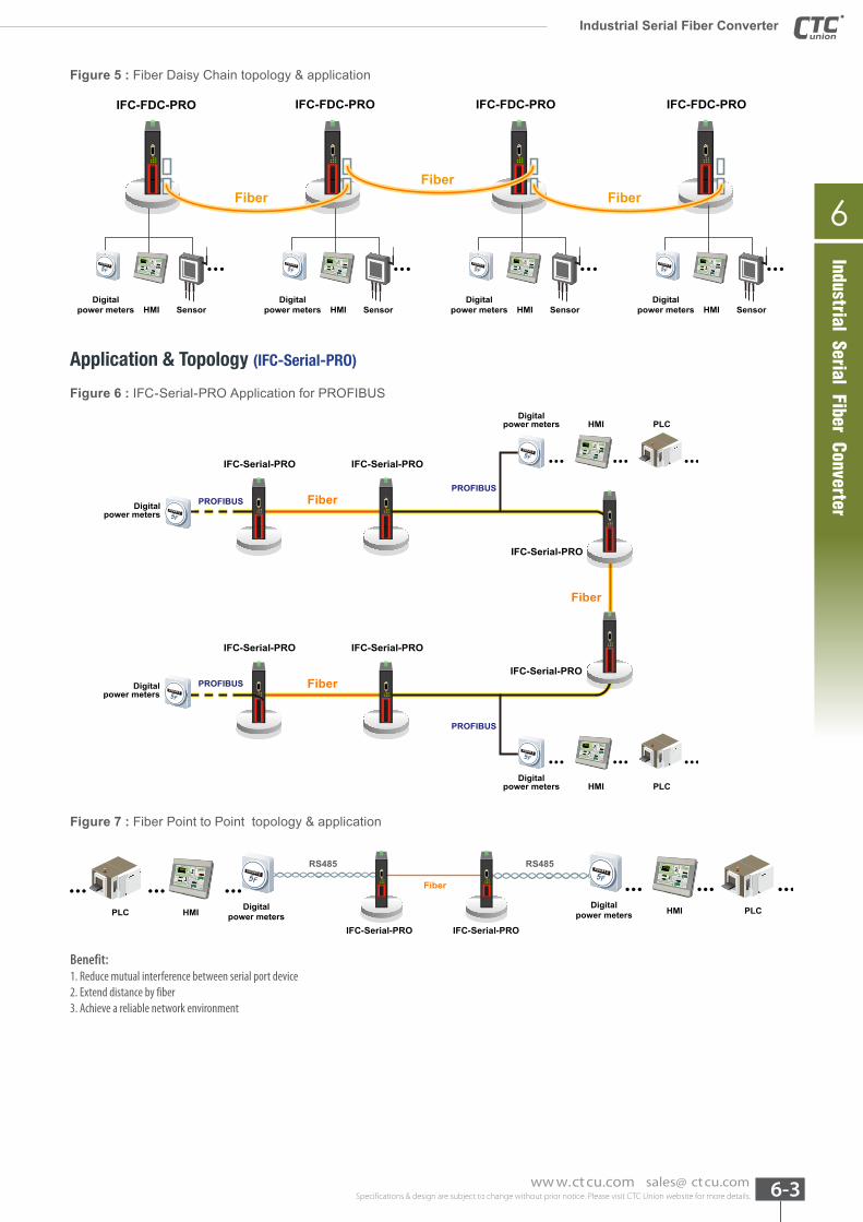
Figure 5 : Fiber Daisy Chain topology & application
Figure 6 : IFC-Serial-PRO Application for PROFIBUS
5F000412
Digitalpower meters SensorHMI
IFC-FDC-PRO
5F000412
Digitalpower meters SensorHMI
IFC-FDC-PRO
5F000412
Digitalpower meters SensorHMI
IFC-FDC-PRO
Digitalpower meters SensorHMI
5F000412
IFC-FDC-PRO
FiberFiber
Fiber
Application & Topology (IFC-Serial-PRO)
Fiber
Fiber
PROFIBUSPROFIBUS
PROFIBUS
PROFIBUS
Fiber
IFC-Serial-PRO
IFC-Serial-PRO IFC-Serial-PRO
PLCDigital
power meters HMI
5F000412
PLCDigital
power meters HMI
5F000412
IFC-Serial-PRO
IFC-Serial-PRO
IFC-Serial-PRO
Digitalpower meters 5F
000412
Digitalpower meters 5F
000412
Figure 7 : Fiber Point to Point topology & application
5F000412
Digitalpower meters HMI PLC
RS485 RS485
Fiber
HMIPLC
5F000412
Digitalpower meters
IFC-Serial-PRO IFC-Serial-PRO
Benefit:1. Reduce mutual interference between serial port device2. Extend distance by fiber3. Achieve a reliable network environment
Specifications & design are subject to change without prior notice. Please visit CTC Union website for more details. 6-4 ww w.ct cu.com sales@ ct cu.com
Industrial Serial Fiber Converter
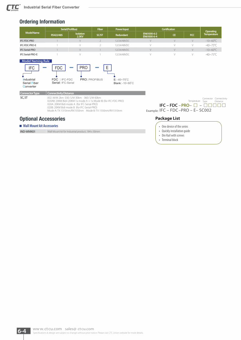
Model NameSerial (ProfiBus) Fiber Power Input Certification
Operating TemperatureRS422/485 Isolation
2.5KV SC/ST Redundant EN61000-6-2EN61000-6-4 CE FCC
IFC-FDC-PRO 1 V 2 12/24/48VDC V V V -10~60°CIFC-FDC-PRO-E 1 V 2 12/24/48VDC V V V -40~75°CIFC-Serial-PRO 1 V 1 12/24/48VDC V V V -10~60°CIFC-Serial-PRO-E 1 V 1 12/24/48VDC V V V -40~75°C
IFC FDC EPRO
IndustrialSerial FiberConverter
FDC : IFC-FDC PRO: PROFIBUSSerial: IFC-Serial
E: -40~75 CBlank: -10~60 C
Model Naming Rule
Connector Type Connectivity DistanceSC, ST 002: M/M 2km 030: S/M 30km 060: S/M 60km
020AB: 20KM Bidi (20KM 1x mode A + 1x Mode B) (for IFC-FDC-PRO)020A: 20KM Bidi mode A (for IFC-Serial-PRO)020B: 20KM Bidi mode B (for IFC-Serial-PRO)Mode A: TX 1310nm/RX1550nm Mode B: TX 1550nm/RX1310nm
Optional Accessories
IND-WMK01 Wall Mount kit for Industrial product, 184 x 30mm
Connector Connectivity Temperature Type Distance
IFC – FDC –PRO– □ – □□□□□Example: IFC – FDC –PRO – E– SC002
Package List
• One device of the series • Quickly installation guide • Din Rail with screws • Terminal block
Wall Mount kit Accessories
Ordering Information
Specifications & design are subject to change without prior notice. Please visit CTC Union website for more details. 6-5ww w.ct cu.com sales@ ct cu.com
6
Industrial Serial Fiber Converter Industrial Serial Fiber Converter
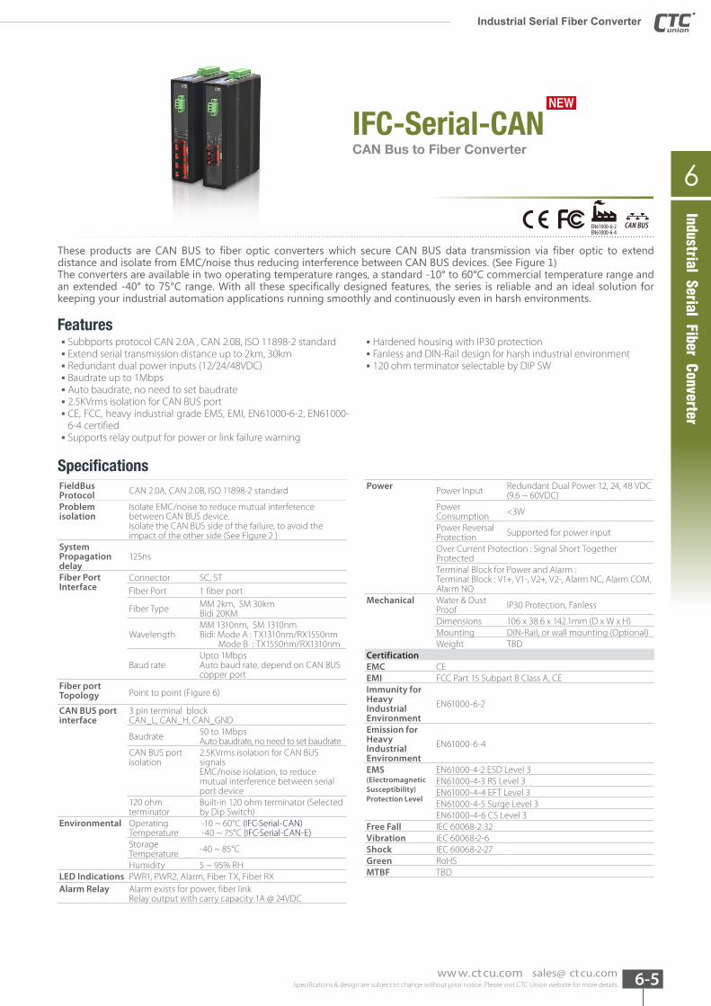
IFC-Serial-CANCAN Bus to Fiber Converter
NEWNEW
These products are CAN BUS to fiber optic converters which secure CAN BUS data transmission via fiber optic to extend distance and isolate from EMC/noise thus reducing interference between CAN BUS devices. (See Figure 1) The converters are available in two operating temperature ranges, a standard -10° to 60°C commercial temperature range and an extended -40° to 75°C range. With all these specifically designed features, the series is reliable and an ideal solution for keeping your industrial automation applications running smoothly and continuously even in harsh environments.
Features ▪ Subbports protocol CAN 2.0A , CAN 2.0B, ISO 11898-2 standard ▪ Extend serial transmission distance up to 2km, 30km ▪ Redundant dual power inputs (12/24/48VDC) ▪ Baudrate up to 1Mbps ▪ Auto baudrate, no need to set baudrate ▪ 2.5KVrms isolation for CAN BUS port ▪ CE, FCC, heavy industrial grade EMS, EMI, EN61000-6-2, EN61000-6-4 certified ▪ Supports relay output for power or link failure warning
▪ Hardened housing with IP30 protection ▪ Fanless and DIN-Rail design for harsh industrial environment ▪ 120 ohm terminator selectable by DIP SW
SpecificationsPower Power Input Redundant Dual Power 12, 24, 48 VDC
(9.6 ~ 60VDC)Power Consumption <3W
Power Reversal Protection Supported for power input
Over Current Protection : Signal Short Together ProtectedTerminal Block for Power and Alarm : Terminal Block : V1+, V1-, V2+, V2-, Alarm NC, Alarm COM, Alarm NO
Mechanical Water & Dust Proof IP30 Protection, Fanless
Dimensions 106 x 38.6 x 142.1mm (D x W x H)Mounting DIN-Rail, or wall mounting (Optional) Weight TBD
CertificationEMC CEEMI FCC Part 15 Subpart B Class A, CEImmunity for Heavy Industrial Environment
EN61000-6-2
Emission for Heavy Industrial Environment
EN61000-6-4
EMS(Electromagnetic Susceptibility) Protection Level
EN61000-4-2 ESD Level 3EN61000-4-3 RS Level 3EN61000-4-4 EFT Level 3EN61000-4-5 Surge Level 3 EN61000-4-6 CS Level 3
Free Fall IEC 60068-2-32Vibration IEC 60068-2-6Shock IEC 60068-2-27Green RoHSMTBF TBD
FieldBus Protocol CAN 2.0A, CAN 2.0B, ISO 11898-2 standard
Problem isolation
Isolate EMC/noise to reduce mutual interference between CAN BUS device. Isolate the CAN BUS side of the failure, to avoid the impact of the other side (See Figure 2 )
System Propagation delay
125ns
Fiber Port Interface
Connector SC, STFiber Port 1 fiber port
Fiber Type MM 2km, SM 30km Bidi 20KM
WavelengthMM 1310nm, SM 1310nmBidi: Mode A : TX1310nm/RX1550nm Mode B : TX1550nm/RX1310nm
Baud rate Upto 1MbpsAuto baud rate, depend on CAN BUS copper port
Fiber port Topology Point to point (Figure 6)
CAN BUS port interface
3 pin terminal blockCAN_L, CAN_H, CAN_GND
Baudrate 50 to 1MbpsAuto baudrate, no need to set baudrate
CAN BUS port isolation
2.5KVrms isolation for CAN BUS signalsEMC/noise isolation, to reduce mutual interference between serial port device
120 ohm terminator
Built-in 120 ohm terminator (Selected by Dip Switch)
Environmental Operating Temperature
-10 ~ 60°C (IFC-Serial-CAN) -40 ~ 75°C (IFC-Serial-CAN-E)
Storage Temperature -40 ~ 85°C
Humidity 5 ~ 95% RHLED Indications PWR1, PWR2, Alarm, Fiber TX, Fiber RXAlarm Relay Alarm exists for power, fiber link
Relay output with carry capacity 1A @ 24VDC
Industrial Serial Fiber Converter
CAN BUSEN61000-6-2EN61000-6-4
Specifications & design are subject to change without prior notice. Please visit CTC Union website for more details. 6-6 ww w.ct cu.com sales@ ct cu.com
Industrial Serial Fiber Converter
Application & Topology
Fiber
Fiber
CAN BUSCAN BUS
CAN BUS
CAN BUS
Fiber
IFC-Serial-CAN
IFC-Serial-CAN
PLC(CAN Device)Dashboard
IFC-Serial-CAN
IFC-Serial-CAN
IFC-Serial-CAN
Sensor
IFC-Serial-CAN
80
Dashboard
80
Dashboard
80
PLC(CAN Device)Dashboard Sensor
80
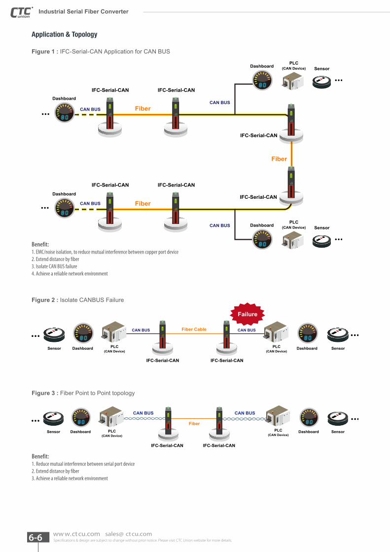
Figure 1 : IFC-Serial-CAN Application for CAN BUS
Benefit:1. EMC/noise isolation, to reduce mutual interference between copper port device 2. Extend distance by fiber 3. Isolate CAN BUS failure 4. Achieve a reliable network environment
Figure 2 : Isolate CANBUS Failure
Fiber Cable CAN BUSCAN BUS
IFC-Serial-CANIFC-Serial-CAN
Failure
PLC(CAN Device)
PLC(CAN Device)
SensorSensor Dashboard
80
Dashboard
80
Figure 3 : Fiber Point to Point topology
CAN BUSCAN BUS
Fiber
IFC-Serial-CAN IFC-Serial-CAN
PLC(CAN Device)
SensorSensor PLC(CAN Device)
Dashboard
80
Dashboard
80
Benefit:1. Reduce mutual interference between serial port device2. Extend distance by fiber3. Achieve a reliable network environment
Specifications & design are subject to change without prior notice. Please visit CTC Union website for more details. 6-7ww w.ct cu.com sales@ ct cu.com
6
Industrial Serial Fiber Converter Industrial Serial Fiber Converter
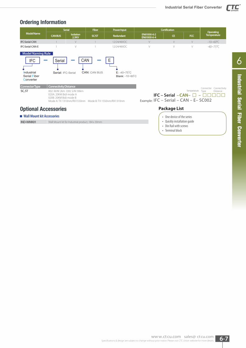
Model NameSerial Fiber Power Input Certification
Operating TemperatureCAN BUS Isolation
2.5KV SC/ST Redundant EN61000-6-2EN61000-6-4 CE FCC
IFC-Serial-CAN 1 V 1 12/24/48VDC V V V -10~60°CIFC-Serial-CAN-E 1 V 1 12/24/48VDC V V V -40~75°C
IFC Serial ECAN
IndustrialSerial FiberConverter
CAN: CAN BUSSerial: IFC-Serial E: -40~75 CBlank: -10~60 C
Model Naming Rule
Connector Type Connectivity DistanceSC, ST 002: M/M 2km 030: S/M 30km
020A: 20KM Bidi mode A020B: 20KM Bidi mode BMode A: TX 1310nm/RX1550nm Mode B: TX 1550nm/RX1310nm
Optional Accessories
IND-WMK01 Wall Mount kit for Industrial product, 184 x 30mm
Connector Connectivity Temperature Type Distance
IFC – Serial – CAN– □ – □□□□□Example: IFC – Serial – CAN – E– SC002
Package List
• One device of the series • Quickly installation guide • Din Rail with screws • Terminal block
Wall Mount kit Accessories
Ordering Information
Industrial Serial Fiber Converter
Specifications & design are subject to change without prior notice. Please visit CTC Union website for more details. 6-8 ww w.ct cu.com sales@ ct cu.com
Industrial Serial Fiber Converter
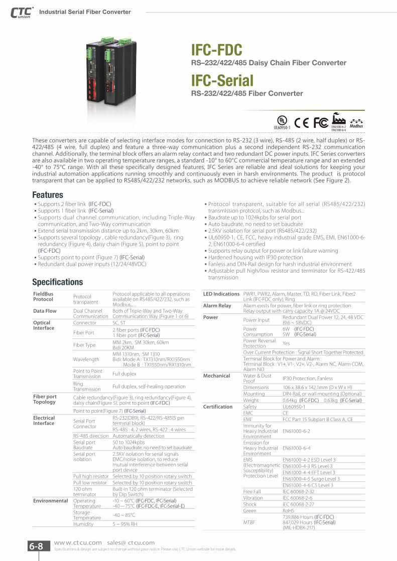
IFC-Serial
IFC-FDC
RS-232/422/485 Fiber Converter
RS–232/422/485 Daisy Chain Fiber Converter
These converters are capable of selecting interface modes for connection to RS-232 (3 wire), RS-485 (2 wire, half duplex) or RS-422/485 (4 wire, full duplex) and feature a three-way communication plus a second independent RS-232 communication channel. Additionally, the terminal block offers an alarm relay contact and two redundant DC power inputs. IFC Series converters are also available in two operating temperature ranges, a standard -10° to 60°C commercial temperature range and an extended -40° to 75°C range. With all these specifically designed features, IFC Series are reliable and ideal solutions for keeping your industrial automation applications running smoothly and continuously even in harsh environments. The product is protocol transparent that can be applied to RS485/422/232 networks, such as MODBUS to achieve reliable network (See Figure 2).
Features
Specifications
▪ Supports 2 fiber link (IFC-FDC) ▪ Supports 1 fiber link (IFC-Serial) ▪ Supports dual channel communication, including Triple-Way communication, and Two-Way communication ▪ Extend serial transmission distance up to 2km, 30km, 60km ▪ Supports several topology , cable redundancy(Figure 3), ring redundancy (Figure 4), daisy chain (Figure 5), point to point (IFC-FDC) ▪ Supports point to point (Figure 7) (IFC-Serial) ▪ Redundant dual power inputs (12/24/48VDC)
▪ Protocol transparent, suitable for all serial (RS485/422/232) transmission protocol, such as Modbus... ▪ Baudrate up to 1024kpbs for serial port ▪ Auto baudrate, no need to set baudrate ▪ 2.5KV isolation for serial port (RS485/422/232) ▪ UL60950-1, CE, FCC, heavy industrial grade EMS, EMI, EN61000-6-2, EN61000-6-4 certified ▪ Supports relay output for power or link failure warning ▪ Hardened housing with IP30 protection ▪ Fanless and DIN-Rail design for harsh industrial environment ▪ Adjustable pull high/low resistor and terminator for RS-422/485 transmission
LED Indications PWR1, PWR2, Alarm, Master, TD, RD, Fiber Link, Fiber2 Link (IFC-FDC only), Ring
Alarm Relay Alarm exists for power, fiber link or ring protectionRelay output with carry capacity 1A @ 24VDC
Power Power Input Redundant Dual Power 12, 24, 48 VDC (9.6 ~ 58VDC)
Power Consumption
6W (IFC-FDC)5W (IFC-Serial)
Power Reversal Protection Yes
Over Current Protection : Signal Short Together ProtectedTerminal Block for Power and Alarm : Terminal Block : V1+, V1-, V2+, V2-, Alarm NC, Alarm COM, Alarm NO
Mechanical Water & Dust Proof IP30 Protection, Fanless
Dimensions 106 x 38.6 x 142.1mm (D x W x H)Mounting DIN-Rail, or wall mounting (Optional) Weight 0.64kg (IFC-FDC) 0.63kg (IFC-Serial)
Certification Safety UL60950-1EMC CEEMI FCC Part 15 Subpart B Class A, CEImmunity for Heavy Industrial Environment
EN61000-6-2
Emission for Heavy Industrial Environment
EN61000-6-4
EMS(Electromagnetic Susceptibility) Protection Level
EN61000-4-2 ESD Level 3EN61000-4-3 RS Level 3EN61000-4-4 EFT Level 3EN61000-4-5 Surge Level 3 EN61000-4-6 CS Level 3
Free Fall IEC 60068-2-32Vibration IEC 60068-2-6Shock IEC 60068-2-27Green RoHS
MTBF739,886 Hours (IFC-FDC) 847,029 Hours (IFC-Serial) (MIL-HDBK-217)
FieldBus Protocol Protocol
transparent
Protocol applicable to all operations available on RS485/422/232, such as Modbus,…
Data Flow Dual Channel Communication
Both of Triple-Way and Two-Way Communication Way (Figure 1 or 6)
Optical Interface
Connector SC, ST
Fiber Port 2 fiber ports (IFC-FDC)1 fiber port (IFC-Serial)
Fiber Type MM 2km, SM 30km, 60km Bidi 20KM
WavelengthMM 1310nm, SM 1310Bidi: Mode A : TX1310nm/RX1550nm Mode B : TX1550nm/RX1310nm
Point to Point Transmission Full duplex
Ring Transmission Full duplex, self-healing operation
Fiber port Topology
Cable redundancy(Figure 3), ring redundancy(Figure 4), daisy chain(Figure 5), point to point (IFC-FDC)
Point to point(Figure 7) (IFC-Serial)Electrical Interface Serial Port
Connector
RS-232(DB9), RS-422/RS-485(5 pin terminal block)RS-485 : 4, 2 wires, RS-422 : 4 wires
RS-485 direction Automatically detectionSerial port Baudrate
50 to 1024kpbsAuto baudrate, no need to set baudrate
Serial port isolation
2.5KV isolation for serial signalsEMC/noise isolation, to reduce mutual interference between serial port device
Pull high resistor Selected by 10 position rotary switchPull low resistor Selected by 10 position rotary switch120 ohm terminator
Built-in 120 ohm terminator (Selected by Dip Switch)
Environmental Operating Temperature
-10 ~ 60°C (IFC-FDC, IFC-Serial)-40 ~ 75°C (IFC-FDC-E, IFC-Serial-E)
Storage Temperature -40 ~ 85°C
Humidity 5 ~ 95% RH
ModbusUL60950-1 EN61000-6-2EN61000-6-4
Specifications & design are subject to change without prior notice. Please visit CTC Union website for more details. 6-9ww w.ct cu.com sales@ ct cu.com
6
Industrial Serial Fiber Converter
Industrial Serial Fiber Converter Industrial Serial Fiber Converter
Application & Topology (IFC-FDC)
TX/RX
TX/RX
RS-422/485
Isolation Terminal Block
DB9Fiber1/2 Logic
RS-232 1TX/RX
RS-232 2TX/RX
SG common
CH 2
CH 1
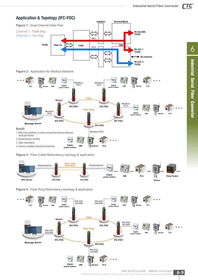
Figure 1 : Dual Channel Data Flow
Figure 2 : Application for Modbus Network
Channel 1 : Triple WayChannel 2 : Two Way
5F000412
OPC Server IFC-FDC IFC-FDC
Fiber CableRedundant
Digitalpower meters
Sensor
Relay OutputHMI PLC
RS485/422/232 RS485/422/232
Message ServerIFC-FDC
IFC-FDC IFC-FDC
IFC-FDC IFC-FDCFiber Ring
FiberMaster
ModbusRTU
ModbusRTU
Modbus RTU
ModbusRTU
ModbusRTU Digital
power metersSensorHMI
5F000412
Digitalpower meters
Sensor HMIPLC
5F000412
PLC
Digitalpower meters
SensorHMI
5F000412
PLC
Digitalpower meters
SensorHMI PLC
5F000412
Message ServerIFC-FDC
IFC-FDC IFC-FDC
IFC-FDC IFC-FDCFiber Ring
FiberMaster
Digitalpower meters
SensorHMI
5F000412
Digitalpower meters
Sensor HMIPLC
5F000412
PLC
Digitalpower meters
SensorHMI
5F000412
PLC
RS-232/422/485
RS-232/422/485
RS-232/422/485
RS-232/422/485
RS-232/422/485
Digitalpower meters
SensorHMI PLC
5F000412
Benefit:1. EMC/noise isolation, to reduce mutual interference between serial port device2. Extend distance by fiber3. Cable redundancy 4. Achieve a reliable network environment
Figure 4 : Fiber Ring Redundancy topology & application
Figure 3 : Fiber Cable Redundancy topology & application
Specifications & design are subject to change without prior notice. Please visit CTC Union website for more details. 6-10 ww w.ct cu.com sales@ ct cu.com
Industrial Serial Fiber Converter
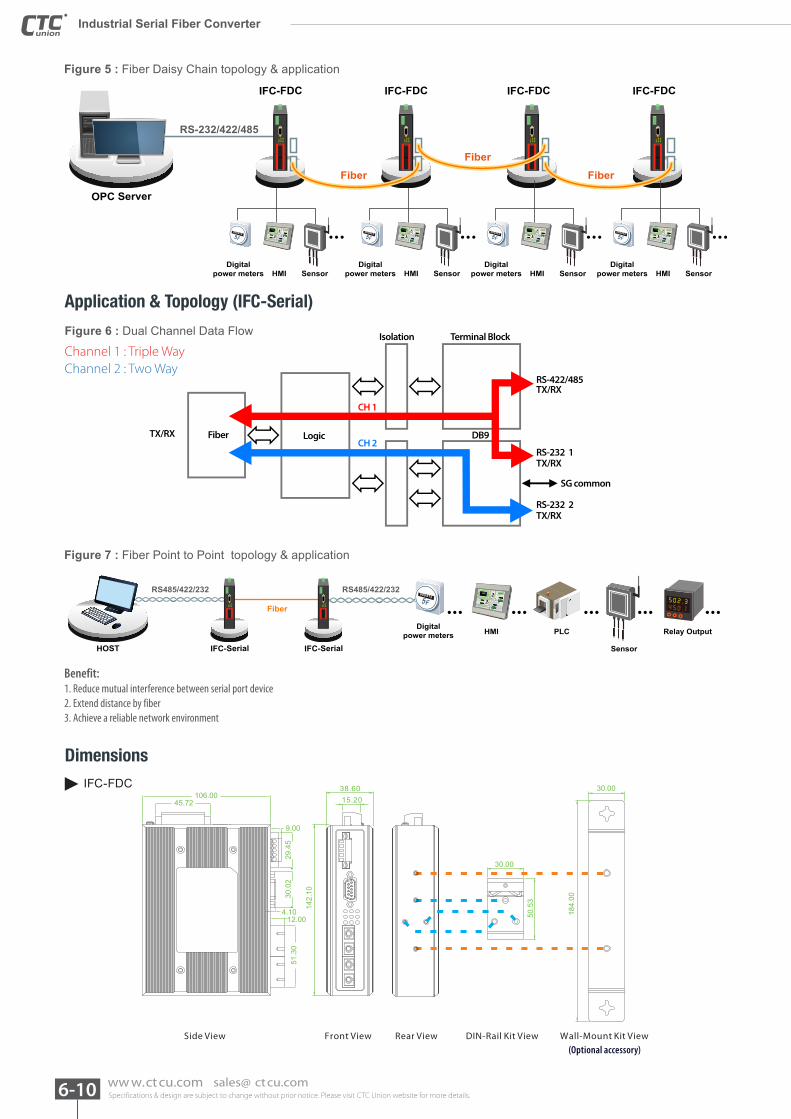
Figure 5 : Fiber Daisy Chain topology & application
5F000412
RS-232/422/485
OPC Server
IFC-FDC IFC-FDC IFC-FDC IFC-FDC
Digitalpower meters SensorHMI
Digitalpower meters SensorHMI
5F000412
Digitalpower meters SensorHMI
5F000412
Digitalpower meters SensorHMI
5F000412
Fiber Fiber
Fiber
Application & Topology (IFC-Serial)
Figure 6 : Dual Channel Data Flow
TX/RX
TX/RX
RS-422/485
Isolation Terminal Block
DB9Fiber Logic
RS-232 1TX/RX
RS-232 2TX/RX
SG common
CH 2
CH 1
Channel 1 : Triple WayChannel 2 : Two Way
Figure 7 : Fiber Point to Point topology & application
5F000412
Digitalpower meters
Sensor
Relay OutputHMI PLC
RS485/422/232 RS485/422/232
Fiber
HOST IFC-Serial IFC-Serial
Benefit:1. Reduce mutual interference between serial port device2. Extend distance by fiber3. Achieve a reliable network environment
Dimensions
38.60
30.00
30.00
50.5
3
184.
00
15.20
142.
10
45.72106.00
51.3
0
12.00
29.4
5
9.00
30.0
2
4.10
Side View Front View Rear View DIN-Rail Kit View Wall-Mount Kit View
IFC-FDC
(Optional accessory)
Specifications & design are subject to change without prior notice. Please visit CTC Union website for more details. 6-11ww w.ct cu.com sales@ ct cu.com
6
Industrial Serial Fiber Converter Industrial Serial Fiber C
onverterIndustrial Serial Fiber Converter
Side View Front View Rear View DIN-Rail Kit View Wall-Mount Kit View
38.60
30.00
30.00
50.5
3
184.
00
15.20
142.
10
45.72106.00
25.4
0
12.00
29.4
5
9.00
30.0
2
4.10
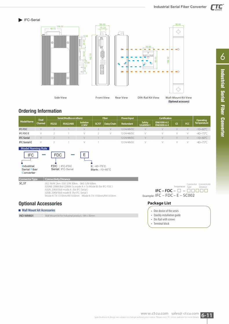
IFC-Serial
(Optional accessory)
Model NameDual
Channel
Serial (ModBus or others) Fiber Power Input CertificationOperating
TemperatureRS232 RS422/485 Isolation 2.5KV SC/ST Daisy Chain Redundant Safety
UL60950-1EN61000-6-2EN61000-6-4 CE FCC
IFC-FDC V 2 1 V 2 V 12/24/48VDC V V V V -10~60°CIFC-FDC-E V 2 1 V 2 V 12/24/48VDC V V V V -40~75°C
IFC-Serial V 2 1 V 1 12/24/48VDC V V V V -10~60°C
IFC-Serial-E V 2 1 V 1 12/24/48VDC V V V V -40~75°C
IFC FDC E
IndustrialSerial FiberConverter
FDC : IFC-FDCSerial: IFC-Serial
E: -40~75 CBlank: -10~60 C
Model Naming Rule
Connector Type Connectivity DistanceSC, ST 002: M/M 2km 030: S/M 30km 060: S/M 60km
020AB: 20KM Bidi (20KM 1x mode A + 1x Mode B) (for IFC-FDC )020A: 20KM Bidi mode A (for IFC-Serial )020B: 20KM Bidi mode B (for IFC-Serial )Mode A: TX 1310nm/RX1550nm Mode B: TX 1550nm/RX1310nm
Optional Accessories
IND-WMK01 Wall Mount kit for Industrial product, 184 x 30mm
Connector Connectivity Temperature Type Distance
IFC – FDC – □ – □□□□□Example: IFC – FDC – E – SC002
Package List
• One device of the series • Quickly installation guide • Din Rail with screws • Terminal block
Wall Mount kit Accessories
Ordering Information
Specifications & design are subject to change without prior notice. Please visit CTC Union website for more details. 6-12 ww w.ct cu.com sales@ ct cu.com
Ethernet Serial Server
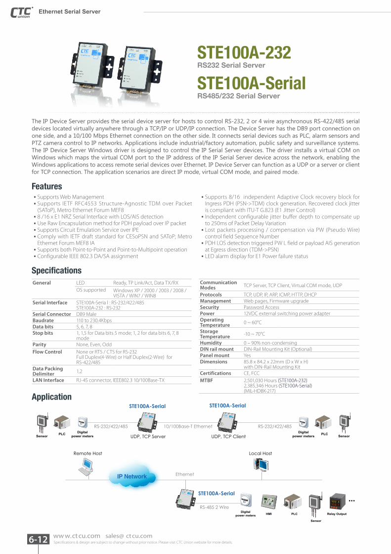
STE100A-232
STE100A-SerialRS232 Serial Server
RS485/232 Serial Server
The IP Device Server provides the serial device server for hosts to control RS-232, 2 or 4 wire asynchronous RS-422/485 serial devices located virtually anywhere through a TCP/IP or UDP/IP connection. The Device Server has the DB9 port connection on one side, and a 10/100 Mbps Ethernet connection on the other side. It connects serial devices such as PLC, alarm sensors and PTZ camera control to IP networks. Applications include industrial/factory automation, public safety and surveillance systems. The IP Device Server Windows driver is designed to control the IP Serial Server devices. The driver installs a virtual COM on Windows which maps the virtual COM port to the IP address of the IP Serial Server device across the network, enabling the Windows applications to access remote serial devices over Ethernet. IP Device Server can function as a UDP or a server or client for TCP connection. The application scenarios are direct IP mode, virtual COM mode, and paired mode.
Features
Specifications
▪ Supports Web Management ▪ Supports IETF RFC4553 Structure-Agnostic TDM over Packet (SAToP), Metro Ethernet Forum MEF8 ▪ 8 /16 x E1 NRZ Serial Interface with LOS/AIS detection ▪ Use Raw Encapsulation method for PDH payload over IP packet ▪ Supports Circuit Emulation Service over IPE ▪ Comply with IETF draft standard for CESoPSN and SAToP; Metro Ethernet Forum MEF8 IA ▪ Supports both Point-to-Point and Point-to-Multipoint operation ▪ Configurable IEEE 802.3 DA/SA assignment
▪ Supports 8/16 independent Adaptive Clock recovery block for Ingress PDH (PSN->TDM) clock generation. Recovered clock jitter is compliant with ITU-T G.823 (E1 Jitter Control) ▪ Independent configurable jitter buffer depth to compensate up to 250ms of Packet Delay Variation ▪ Lost packets processing / compensation via PW (Pseudo Wire) control field Sequence Number ▪ PDH LOS detection triggered PW L field or payload AIS generation at Egress direction (TDM->PSN) ▪ LED alarm display for E1 Power failure status
General LED Ready, TP Link/Act, Data TX/RXOS supported Windows XP / 2000 / 2003 / 2008 /
VISTA / WIN7 / WIN8Serial Interface STE100A-Seria l : RS-232/422/485
STE100A-232 : RS-232Serial Connector DB9 MaleBaudrate 110 to 230.4KbpsData bits 5, 6, 7, 8Stop bits 1, 1,5 for Data bits 5 mode; 1, 2 for data bits 6, 7, 8
modeParity None, Even, OddFlow Control None or RTS / CTS for RS-232
Full Duplex(4-Wire) or Half Duplex(2-Wire) for RS-422/485
Data Packing Delimiter 1,2
LAN Interface RJ-45 connector, IEEE802.3 10/100Base-TX
Communication Modes TCP Server, TCP Client, Virtual COM mode, UDP
Protocols TCP, UDP, IP, ARP, ICMP, HTTP, DHCPManagement Web pages, Firmware upgradeSecurity Password AccessPower 12VDC external switching power adapterOperating Temperature 0 ~ 60°C
Storage Temperature -10 ~ 70°C
Humidity 0 – 90% non-condensingDIN rail mount DIN-Rail Mounting Kit (Optional)Panel mount YesDimensions 85.8 x 84.2 x 22mm (D x W x H)
with DIN-Rail Mounting Kit Certifications CE, FCCMTBF 2,501,030 Hours (STE100A-232)
2,385,346 Hours (STE100A-Serial)(MIL-HDBK-217)
Application
RS-232/422/485 10/100Base-T Ethernet
STE100A-Serial STE100A-Serial
RS-232/422/485
UDP, TCP Server UDP, TCP Client
Remote Host
IP Network Ethernet
Local Host
STE100A-Serial
RS-485 2 Wire
Digitalpower meters
Digitalpower metersSensor Sensor
5F000412
5F000412
PLC PLC
5F000412
Digitalpower meters
Sensor
Relay OutputHMI PLC
Specifications & design are subject to change without prior notice. Please visit CTC Union website for more details. 6-13ww w.ct cu.com sales@ ct cu.com
6
Ethernet Serial ServerEthernet Serial Server
Ethernet Serial Server
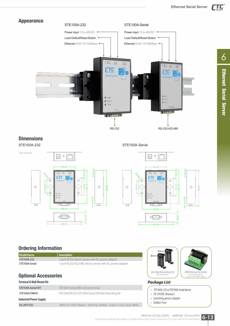
AppearanceSTE100A-232 STE100A-Serial
RS-232 RS-232/422/485
Power input 12 to 48VDC
Load Default/Reset Button
Ethernet RJ45 10/100Mbps
Power input 12 to 48VDC
Load Default/Reset Button
Ethernet RJ45 10/100Mbps
DimensionsSTE100A-232 STE100A-Serial
RS-232 RS-232/422/485RS-232/422/485
Unit: mm (inch)
Ordering InformationModel Name Description
STE100A-232 1-port RS232 device server with AC power adapterSTE100A-Serial 1-port RS232/422/485 device server with AC power adapter
DC-APT/12V -48VDC to 12VDC Adapter - 0.83 Amp, 10 Watts , Output 12 VDC, Input -48VDC
STE100A-Serial-WT STE100A-Serial DB9 wiring terminal
STE100A/DRK01 STE100A/RS232,STE100A/Serial DIN-Rail Mounting Kit
DB9 Wiring TerminalSTE100A-Serial-WT
(only for STE100A-Serial)
Din-Rail Mounting KitSTE100A/DRK01
Package List
• STE100A-232 or STE100A-Serial device • CD (VCOM, Manual ) • Switching power adapter• Rubber Foot
Optional AccessoriesTerminal & Wall Mount Kit
Industrial Power Supply


