
NEWBuildS Tall Wood Building Design Project – Structural Design
and Analysis
Zhiyong Chen & Minghao LiUniversity of New Brunswick, University of British Columbia
www.NEWBuildSCanada.ca

Location and Design Data
North Vancouver: “high earthquake, wind and rain”
Climatic Design Data (Per BCBC 2012)• Ground Snow Load: Ss=3 KPa, Sr=0.3 KPa Plus snow built up
where applicable• Hourly Wind Pressure: 0.35kPa (1/10) and 0.45kPa (1/50)
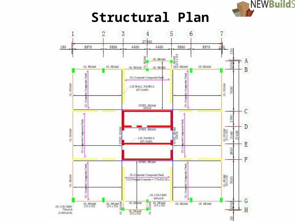
Structural Plan

Lateral load resisting system: SCL core + CLT moment frame (“Strong column-weak beam” balloon-frame)
Gravity resisting system: CLT roof / floors SCL core + CLT moment frame + post-beam frame
Seismic force modification factors: Rd = 2.0 and R0 = 1.5
Connection: HBV wood concrete or HSK hold downs
Structural Scheme

Wind Induced Response
Structural integrity (building structure check and component & cladding check) under ultimate wind loads (1/50, ULS)
Serviceability under service wind loads (1/10) with serviceability criteria (inter-story drift limit = 1/500, SLS)
Building motions and occupant comfort (cross-wind acceleration aw and along-wind acceleration aD)

6
Wind Design Parameters
Pressure CoefficientCp=0.8 for windward wallsCp=0.5 for leeward walls
Internal Pressure CoefficientCpi=-0.45~0.3 Category 2
Exposure B(rough exposure, urban and suburban areas)Ce=0.5(h/12.7)0.5
Cg Gust effect factor calculated by Dynamic procedure

Wind Induced Response
Estimated fundamental frequency 0.25Hz < fn < 1Hz; therefore, Dynamic Procedure is required to calculate gust effect factor.
P=IwqCeCgCp and Pi=IwqCeCgiCpi
Calculations of Ce , Cg , Cp and Cpi follow “NBCC Structural Commentary I Wind Load and Effects”.
Sufficient lateral stiffness is needed to satisfy the drift limit criteria.

8
Beam188 elements (glulam, steel beams and columns);
Shell181 elements (floor diaphragms and shear walls);
Pinned connections;
Combin39 nonlinear springs (for hold-downs, shear connections panel-panel contacts, under development…)
Numerical Models

9
10
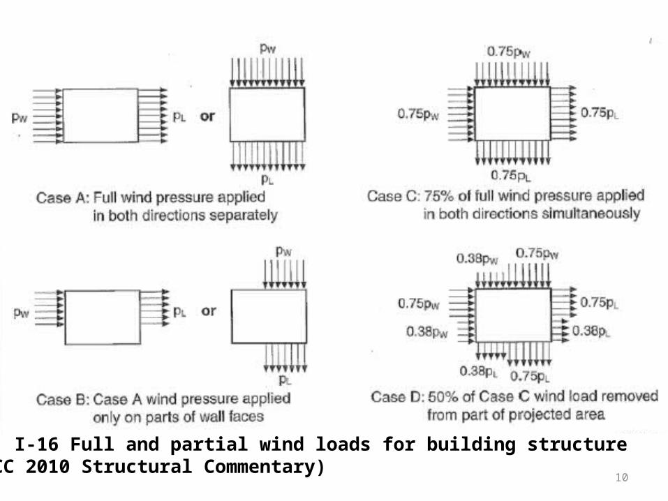
Fig. I-16 Full and partial wind loads for building structure(NBCC 2010 Structural Commentary)

11
Level q (kPa)Cp(windward)
Cp(leeward)
Ce(static method) Cg(static) fi (kN)
2 0.45 0.8 -0.5 0.64 2 863 0.45 0.8 -0.5 0.70 2 944 0.45 0.8 -0.5 0.75 2 1015 0.45 0.8 -0.5 0.79 2 1066 0.45 0.8 -0.5 0.83 2 1117 0.45 0.8 -0.5 0.86 2 1168 0.45 0.8 -0.5 0.89 2 1209 0.45 0.8 -0.5 0.92 2 124
10 0.45 0.8 -0.5 0.95 2 12811 0.45 0.8 -0.5 0.97 2 13112 0.45 0.8 -0.5 1.00 2 13413 0.45 0.8 -0.5 1.02 2 13714 0.45 0.8 -0.5 1.04 2 14015 0.45 0.8 -0.5 1.06 2 14316 0.45 0.8 -0.5 1.08 2 14517 0.45 0.8 -0.5 1.10 2 14818 0.45 0.8 -0.5 1.12 2 15019 0.45 0.8 -0.5 1.13 2 15320 0.45 0.8 -0.5 1.15 2 155
Wind Load (ULS)

12
Roof drift 89 mm (1/640)
Max. Inter-story drift4.8 mm (1/625)
Building Deformations(ULS, Case A)

13
Stresses in LSL Shear Walls (ULS)
14
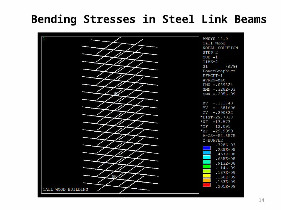
Bending Stresses in Steel Link Beams
15
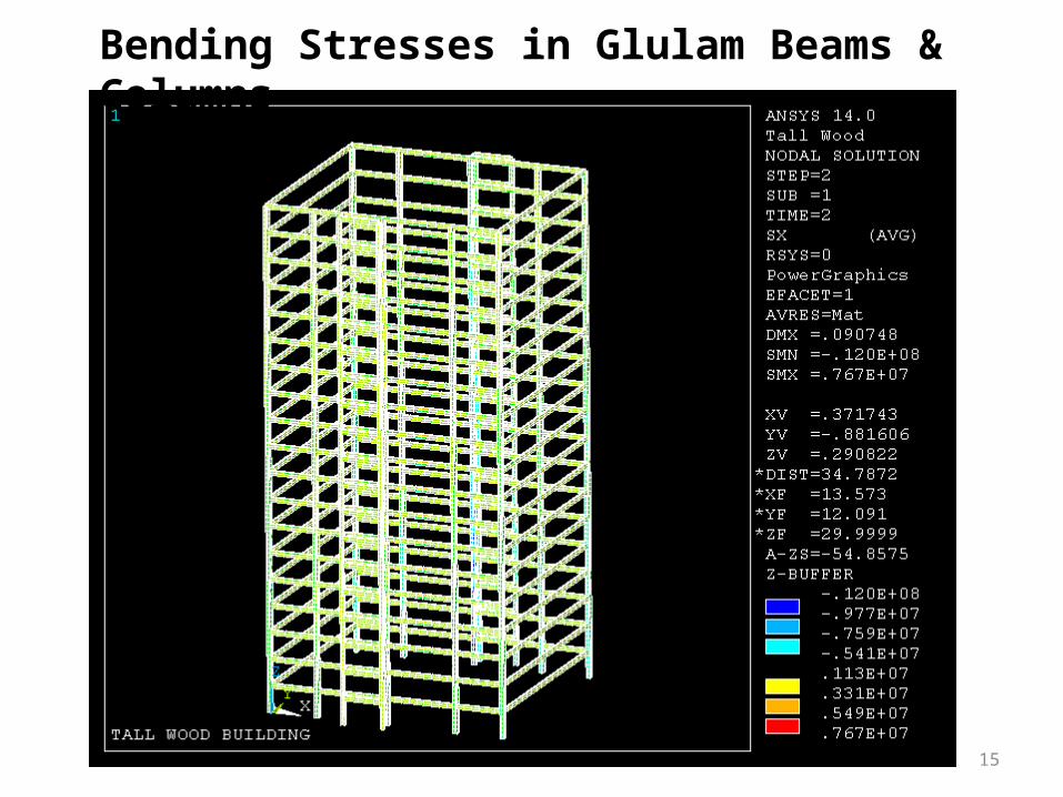
Bending Stresses in Glulam Beams & Columns

16
Lowest Natural Frequency = 0.467 Hz for Dynamic Procedure
Calculation of gust effect factor Cg
Calculation of aw and aD related to building vibrations under serviceability limit state

Thank you for your attention!


