USER GUIDE
NI Camera Link I/O Extension Board (PCIe)The NI Camera Link I/O Extension Board provides additional I/O capabilities for National Instruments PCI Express (PCIe) Camera Link image acquisition devices. This document describes how to install and configure the necessary components to begin using the I/O Extension Board.
The I/O Extension Board offers the following functionality:
• 8 TTL I/O. Refer to the Configuring the TTL I/O Start Condition section for more information.
• 3 optically isolated inputs.
• 3 optically isolated outputs.
• Quadrature encoder input.
• Camera power (+5 V and +12 V).
What You Need to Get StartedYou need the following items to set up and use the I/O Extension Board:
❑ NI Camera Link I/O Extension Board
❑ National Instruments PCIe Camera Link image acquisition device
❑ 50-pin ribbon cable, included in kit
❑ Computer running Microsoft Windows Vista/XP/2000 with at least one available PCIe slot
Note Visit ni.com/info and enter rdvisionvista for more information about National Instruments device compatibility with Windows Vista.
❑ NI Vision Acquisition Software 8.2.0 or later, which includes the NI-IMAQ driver software
Optional EquipmentNational Instruments offers a variety of products for use with the I/O Extension Board, including the following:
❑ Digital I/O cable and horizontal DIN rail terminal block (part number 778790-01)
❑ Digital I/O cable and vertical DIN rail terminal block (part number 778791-01)
Refer to the National Instruments catalog, visit ni.com, or call the National Instruments office nearest you for more specific information about these products.
NI Camera Link I/O Extension Board (PCIe) User Guide 2 ni.com
Related DocumentationThe following documents contain additional information that you may find helpful:
• NI Vision Acquisition Software Release Notes—Contains information about new functionality, minimum system requirements, and installation instructions for the NI-IMAQ driver software.
• Measurement & Automation Explorer Help for NI-IMAQ—Describes how to configure the NI-IMAQ driver software, NI image acquisition devices, and cameras using Measurement & Automation Explorer (MAX).
• NI-IMAQ Help—Contains fundamental programming concepts for the NI-IMAQ driver software and terminology for using NI image acquisition devices.
Safety Information
Caution The following paragraphs contain important safety information you must follow when installing and operating the I/O Extension Board and all devices connecting to the I/O Extension Board.
Do not operate the device in a manner not specified in the documentation. Misuse of the device may result in a hazard and may compromise the safety protection built into the device. If the device is damaged, turn it off and do not use it until service-trained personnel can check its safety. If necessary, return the device to National Instruments for repair.
Keep away from live circuits. Do not remove equipment covers or shields unless you are trained to do so. If signal wires are connected to the device, hazardous voltages can exist even when the equipment is turned off. To avoid a shock hazard, do not perform procedures involving cover or shield removal unless you are qualified to do so. Disconnect all field power prior to removing covers or shields.
If the device is rated for use with hazardous voltages (>30 Vrms, 42.4 Vpk, or 60 Vdc), it may require a safety earth-ground connection wire. Refer to the device specifications for maximum voltage ratings.
Because of the danger of introducing additional hazards, do not install unauthorized parts or modify the device. Use the device only with the chassis, modules, accessories, and cables specified in the installation instructions. All covers and filler panels must be installed while operating the device.
Do not operate the device in an explosive atmosphere or where flammable gases or fumes may be present. Operate the device only at or below the pollution degree stated in the specifications. Pollution consists of any foreign matter—solid, liquid, or gas—that may reduce dielectric strength or surface resistivity. The following is a description of pollution degrees.
• Pollution Degree 1—No pollution or only dry, nonconductive pollution occurs. The pollution has no effect.
• Pollution Degree 2—Normally only nonconductive pollution occurs. Occasionally, nonconductive pollution becomes conductive because of condensation.
• Pollution Degree 3—Conductive pollution or dry, nonconductive pollution occurs. Nonconductive pollution becomes conductive because of condensation.
Clean the device and accessories by brushing off light dust with a soft, nonmetallic brush. Remove other contaminants with a stiff, nonmetallic brush. The unit must be completely dry and free from contaminants before returning it to service.
You must insulate signal connections for the maximum voltage for which the device is rated. Do not exceed the maximum ratings for the device. Remove power from signal lines before connection to or disconnection from the device.

© National Instruments Corporation 3 NI Camera Link I/O Extension Board (PCIe) User Guide
Caution National Instruments measurement products may be classified as either Measurement Category I or II. Operate products at or below the Measurement Category level specified in the hardware specifications.
Measurement Category1: Measurement circuits are subjected to working voltages2 and transient stresses (overvoltage) from the circuit to which they are connected during measurement or test. Measurement Category establishes standardized impulse withstand voltage levels that commonly occur in electrical distribution systems. The following is a description of Measurement (Installation3) Categories:
• Measurement Category I is for measurements performed on circuits not directly connected to the electrical distribution system referred to as MAINS4 voltage. This category is for measurements of voltages from specially protected secondary circuits. Such voltage measurements include signal levels, special equipment, limited-energy parts of equipment, circuits powered by regulated low-voltage sources, and electronics.
• Measurement Category II is for measurements performed on circuits directly connected to the electrical distribution system. This category refers to local-level electrical distribution, such as that provided by a standard wall outlet (e.g., 115 V for U.S. or 230 V for Europe). Examples of Measurement Category II are measurements performed on household appliances, portable tools, and similar products.
• Measurement Category III is for measurements performed in the building installation at the distribution level. This category refers to measurements on hard-wired equipment such as equipment in fixed installations, distribution boards, and circuit breakers. Other examples are wiring, including cables, bus-bars, junction boxes, switches, socket-outlets in the fixed installation, and stationary motors with permanent connections to fixed installations.
UnpackingThe I/O Extension Board ships in an antistatic package to prevent electrostatic discharge from damaging device components. To avoid such damage in handling your device, take the following precautions:
1. Ground yourself using a grounding strap or by touching a grounded object, such as the computer chassis.
2. Touch the antistatic package to a metal part of the computer chassis before removing the device from the package.
Caution Never touch the exposed pins of connectors.
3. Remove the device from the package and inspect it for loose components or any other signs of damage. Notify National Instruments if the device appears damaged in any way. Do not install a damaged device in the computer.
Store the I/O Extension Board in the antistatic package when not in use.
1 Measurement Categories as defined in electrical safety standard IEC 61010-1.2 Working voltage is the highest rms value of an AC or DC voltage that can occur across any particular insulation.3 Measurement Category is also referred to as Installation Category.4 MAINS is defined as the (hazardous live) electrical supply system to which equipment is designed to be connected for the
purpose of powering the equipment. Suitably rated measuring circuits may be connected to the MAINS for measuring purposes.
NI Camera Link I/O Extension Board (PCIe) User Guide 4 ni.com
InstallationThe following instructions are for general installation. Refer to the documentation provided by your computer manufacturer for specific instructions and warnings. Refer to the Specifications section for a list of the typical power requirements for the I/O Extension Board.
1. Install the NI Vision Acquisition Software before installing the I/O Extension Board. Refer to the NI Vision Acquisition Software Release Notes for specific installation instructions.
2. Power off and unplug the computer.
Caution To protect yourself and the computer from electrical hazards, the computer must remain unplugged until the installation is complete.
3. Remove the computer cover to expose the expansion slots.
4. Choose an unused PCIe slot, and remove the corresponding expansion slot cover on the back panel of the computer.
5. Touch a metal part on the computer case to discharge any static electricity that might be on your clothes or body. Static electricity can damage the device.
6. Remove the device from the antistatic package and gently rock the device into the slot. The connection may be tight, but do not force the device into place.
7. Secure the device mounting bracket to the back panel rail of the computer.
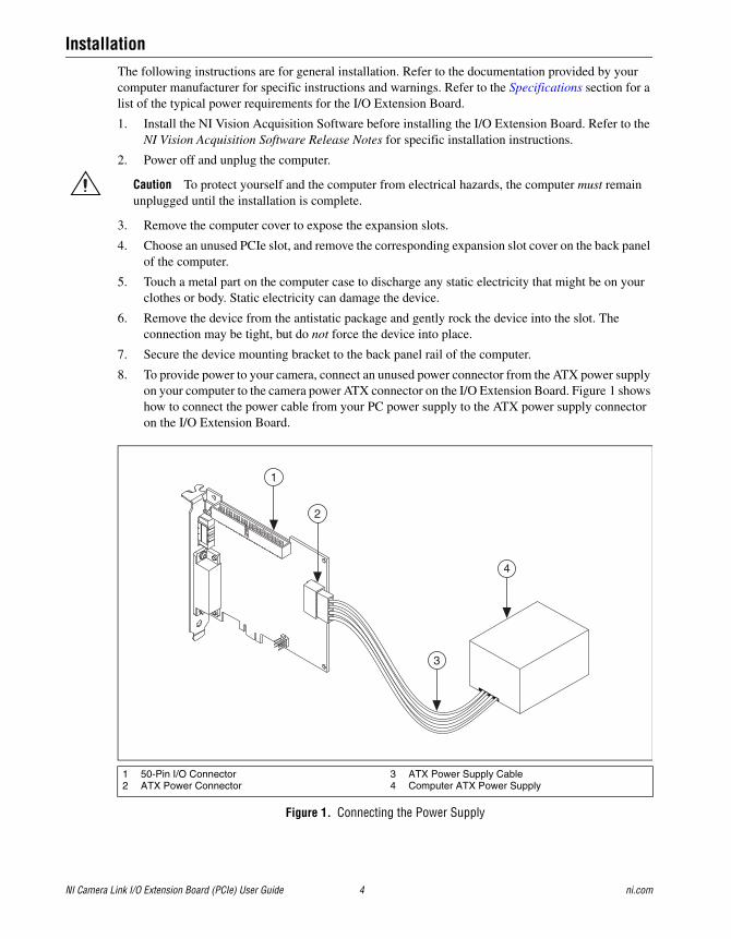
8. To provide power to your camera, connect an unused power connector from the ATX power supply on your computer to the camera power ATX connector on the I/O Extension Board. Figure 1 shows how to connect the power cable from your PC power supply to the ATX power supply connector on the I/O Extension Board.
Figure 1. Connecting the Power Supply
1 50-Pin I/O Connector2 ATX Power Connector
3 ATX Power Supply Cable4 Computer ATX Power Supply
2
1
3
4

© National Instruments Corporation 5 NI Camera Link I/O Extension Board (PCIe) User Guide
9. Connect the 50-pin ribbon cable from the I/O Extension Board to your image acquisition device. Figure 2 shows how to connect the 50-pin ribbon cable from the I/O Extension Board to an image acquisition device that supports the I/O Extension Board.
Figure 2. Connecting the I/O Extension Board to an Image Acquisition Device
10. Replace the computer cover.
11. Plug in and power on the computer.
The I/O Extension Board is now installed and connected to the image acquisition device.
Configuring the TTL I/O Start ConditionThe start condition for the TTL I/O is user-selectable. The TTL I/O can either be pulled high, pulled low, or tri-stated.
• To pull the TTL I/O lines high, connect the jumper to TTL PULL and +5V.
• To pull the TTL I/O lines low, connect the jumper to TTL PULL and GND.
• To tri-state the TTL I/O lines, remove the jumper.
1 I/O Extension Board 2 50-Pin Ribbon Cable 3 Image Acquisition Device
2
1
3
NI Camera Link I/O Extension Board (PCIe) User Guide 6 ni.com
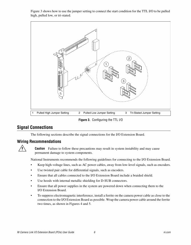
Figure 3 shows how to use the jumper setting to connect the start condition for the TTL I/O to be pulled high, pulled low, or tri-stated.
Figure 3. Configuring the TTL I/O
Signal ConnectionsThe following sections describe the signal connections for the I/O Extension Board.
Wiring Recommendations
Caution Failure to follow these precautions may result in system instability and may cause permanent damage to system components.
National Instruments recommends the following guidelines for connecting to the I/O Extension Board.
• Keep high-voltage lines, such as AC power cables, away from low-level signals, such as encoders.
• Use twisted pair cable for differential signals, such as encoders.
• Ensure that all cables connected to the I/O Extension Board include a braided shield.
• Use hoods with internal metallic shielding for D-SUB connectors.
• Ensure that all power supplies in the system are powered down when connecting them to the I/O Extension Board.
• To suppress electromagnetic interference, install a ferrite on the camera power cable as close to the connection to the I/O Extension Board as possible. Wrap the camera power cable around the ferrite two times, as shown in Figures 4 and 5.
1 Pulled High Jumper Setting 2 Pulled Low Jumper Setting 3 Tri-Stated Jumper Setting
2
3
1

© National Instruments Corporation 7 NI Camera Link I/O Extension Board (PCIe) User Guide
Figure 4. Installing a Ferrite Connector on the Camera Power Cable
Figure 5. Closed Ferrite on the Camera Power Cable
44-Pin D-SUB ConnectionsFigure 6 shows the pinout of the 44-pin D-SUB connector on the front panel of the I/O Extension Board.
Figure 6. 44-Pin D-SUB Connector
1 Power Supply Output Cable 2 Ferrite
1 Power Supply Output Cable 2 Ferrite
2
1
1
2
153044
11631

NI Camera Link I/O Extension Board (PCIe) User Guide 8 ni.com
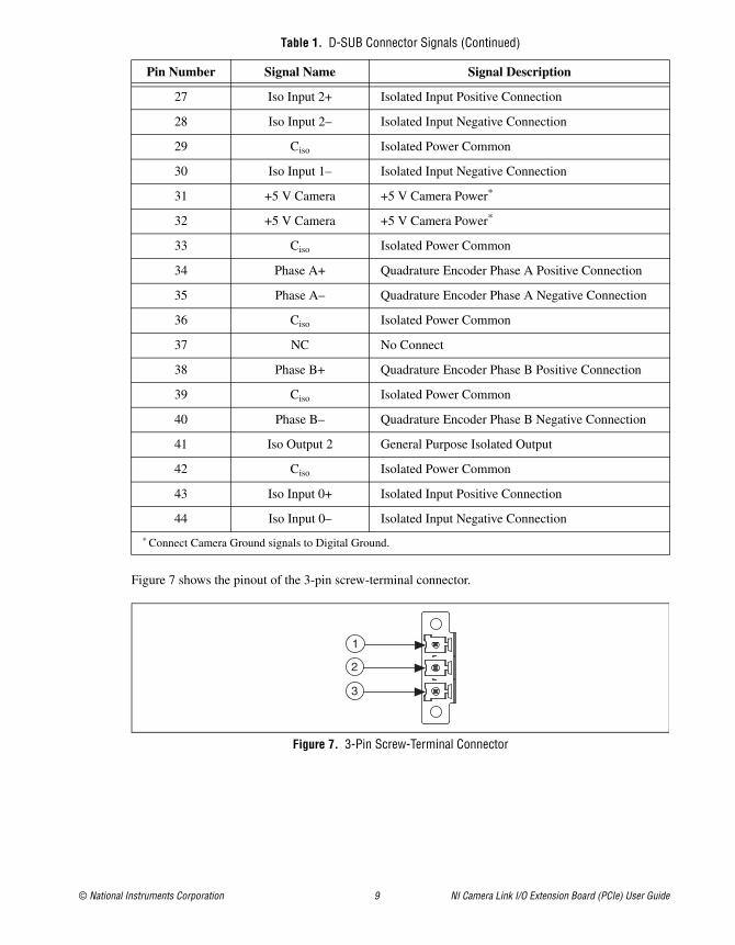
Table 1 lists pin numbers, signal names, and signal descriptions for the 44-pin D-SUB connector.
Table 1. D-SUB Connector Signals
Pin Number Signal Name Signal Description
1 +12 V Camera +12 V Camera Power*
2 Digital Ground Direct connection to Digital Ground on the I/O Extension Board
3 TTL I/O 1 General Purpose TTL Input/Output Line
4 TTL I/O 2 General Purpose TTL Input/Output Line
5 Digital Ground Direct connection to Digital Ground on the I/O Extension Board
6 TTL I/O 3 General Purpose TTL Input/Output Line
7 TTL I/O 4 General Purpose TTL Input/Output Line
8 Digital Ground Direct connection to Digital Ground on the I/O Extension Board
9 NC No Connect
10 Viso Isolated Power
11 Ciso Isolated Power Common
12 Iso Output 0 General Purpose Isolated Output
13 Iso Output 1 General Purpose Isolated Output
14 Ciso Isolated Power Common
15 Iso Input 1+ Isolated Input Positive Connection
16 +12 V Camera +12 V Camera Power*
17 Digital Ground Direct connection to Digital Ground on the I/O Extension Board
18 TTL I/O 5 General Purpose TTL Input/Output Line
19 TTL I/O 6 General Purpose TTL Input/Output Line
20 Digital Ground Direct connection to Digital Ground on the I/O Extension Board
21 TTL I/O 7 General Purpose TTL Input/Output Line
22 TTL I/O 8 General Purpose TTL Input/Output Line
23 Digital Ground Direct connection to Digital Ground on the I/O Extension Board
24 NC No Connect
25 Viso Isolated Power
26 Ciso Isolated Power Common
© National Instruments Corporation 9 NI Camera Link I/O Extension Board (PCIe) User Guide
Figure 7 shows the pinout of the 3-pin screw-terminal connector.
Figure 7. 3-Pin Screw-Terminal Connector
27 Iso Input 2+ Isolated Input Positive Connection
28 Iso Input 2– Isolated Input Negative Connection
29 Ciso Isolated Power Common
30 Iso Input 1– Isolated Input Negative Connection
31 +5 V Camera +5 V Camera Power*
32 +5 V Camera +5 V Camera Power*
33 Ciso Isolated Power Common
34 Phase A+ Quadrature Encoder Phase A Positive Connection
35 Phase A– Quadrature Encoder Phase A Negative Connection
36 Ciso Isolated Power Common
37 NC No Connect
38 Phase B+ Quadrature Encoder Phase B Positive Connection
39 Ciso Isolated Power Common
40 Phase B– Quadrature Encoder Phase B Negative Connection
41 Iso Output 2 General Purpose Isolated Output
42 Ciso Isolated Power Common
43 Iso Input 0+ Isolated Input Positive Connection
44 Iso Input 0– Isolated Input Negative Connection
* Connect Camera Ground signals to Digital Ground.
Table 1. D-SUB Connector Signals (Continued)
Pin Number Signal Name Signal Description
1
3
2

NI Camera Link I/O Extension Board (PCIe) User Guide 10 ni.com
Table 2 lists pin numbers, signal names, and signal descriptions for the 3-pin screw-terminal connector on the I/O Extension Board.
Connecting an Isolated Input to Output DevicesYou can wire an isolated input to both sourcing and sinking output devices. Refer to Figures 8 and 9 for wiring examples by output type. Refer to the Specifications section for information about switching thresholds and current requirements.
Caution Do not apply a voltage greater than 30 VDC to the isolated inputs. Voltages greater than 30 VDC may damage the I/O Extension Board.
Note Isolated inputs are compatible with 5 V logic if the external circuit meets the voltage and current requirements listed in the Specifications section.
Figure 8. Example of Connecting an Isolated Input to a Sourcing Output Device
Table 2. 3-Pin Screw-Terminal Connector Signals
Pin Number Signal Name Signal Description
1 +12 V +12 V Camera Power
2 Ground Ground Reference for Camera Power
3 +5 V +5 V Camera Power
SensorPower
IN+
I/O Extension Board
IN
PNP (Sourcing)Output Device
SensorCommon
Vcc
OptocouplerCurrentLimiter

© National Instruments Corporation 11 NI Camera Link I/O Extension Board (PCIe) User Guide
Figure 9. Example of Connecting an Isolated Input to a Sinking Output Device
Connecting an Isolated Output to an External LoadThe digital output circuit sources current to external loads, as shown in the example in Figure 10.
Note The isolated outputs have current-limiting protection circuitry. If this circuitry is tripped, you can re-enable the outputs by cycling power on the I/O Extension Board or by toggling the output state in the software.
Figure 10. Example of Connecting an Isolated Output to an External Load
Vcc
SensorPower
IN+ CurrentLimiter
I/O Extension Board
IN
NPN (Sinking)Output Device
SensorCommon
Optocoupler
Digital Output
Viso
Ciso
Vcc
I/O Extension Board
Load
CurrentLimiterOptocoupler

NI Camera Link I/O Extension Board (PCIe) User Guide 12 ni.com
Protecting Inductive LoadsWhen an inductive load, such as a relay or solenoid, is connected to an output, a large counter-electromotive force may occur at switching time due to energy stored in the inductive load. This flyback voltage can damage the outputs and the power supply.
To limit flyback voltages at the inductive load, install a flyback diode across the load. Mount the flyback diode as close to the load as possible. Use this protection method if you connect any of the isolated outputs on the I/O Extension Board to an inductive load.
Figure 11 shows an example of using an external flyback diode to protect inductive loads.
Figure 11. Example of Using an External Flyback Diode for Inductive Loads
Connecting to a Quadrature EncoderThe I/O Extension Board accepts either single-ended TTL or differential (RS-422 compatible) line driver inputs. If a single-ended encoder is used, the encoder lines must be connected to the positive connection for each phase.
Shielded encoder cables are recommended for all applications. Unshielded cables are more susceptible to noise and can corrupt the encoder signals.
Note If the encoder cable length is greater than 3.05 m (10 ft), encoders with line driver outputs are recommended.
DigitalOutput
Viso
Ciso
Vcc
I/O Extension Board
ExternalFlyback
Diode for Inductive Loads
Load
CurrentLimiterOptocoupler
© National Instruments Corporation 13 NI Camera Link I/O Extension Board (PCIe) User Guide
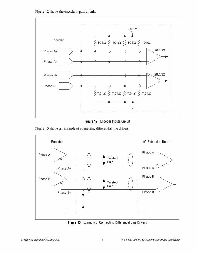
Figure 12 shows the encoder inputs circuit.
Figure 12. Encoder Inputs Circuit
Figure 13 shows an example of connecting differential line drivers.
Figure 13. Example of Connecting Differential Line Drivers
+
–Phase A–
Phase A+
+
–Phase B–
Phase B+
Encoder
+3.3 V
7.5 kΩ
10 kΩ10 kΩ10 kΩ10 kΩ
7.5 kΩ7.5 kΩ7.5 kΩ
26LV32
26LV32
Phase A+
Phase A–Phase A–
Phase ATwistedPair
Phase B+
Phase B–Phase B–
Phase BTwistedPair
Encoder I/O Extension Board
NI Camera Link I/O Extension Board (PCIe) User Guide 14 ni.com
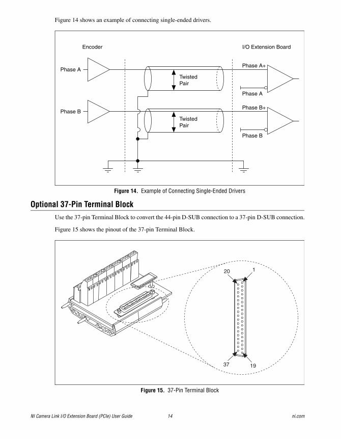
Figure 14 shows an example of connecting single-ended drivers.
Figure 14. Example of Connecting Single-Ended Drivers
Optional 37-Pin Terminal BlockUse the 37-pin Terminal Block to convert the 44-pin D-SUB connection to a 37-pin D-SUB connection.
Figure 15 shows the pinout of the 37-pin Terminal Block.
Figure 15. 37-Pin Terminal Block
Phase A+
Phase A
Phase ATwistedPair
Phase B+
Phase B
Phase BTwistedPair
Encoder I/O Extension Board
120
1937
© National Instruments Corporation 15 NI Camera Link I/O Extension Board (PCIe) User Guide
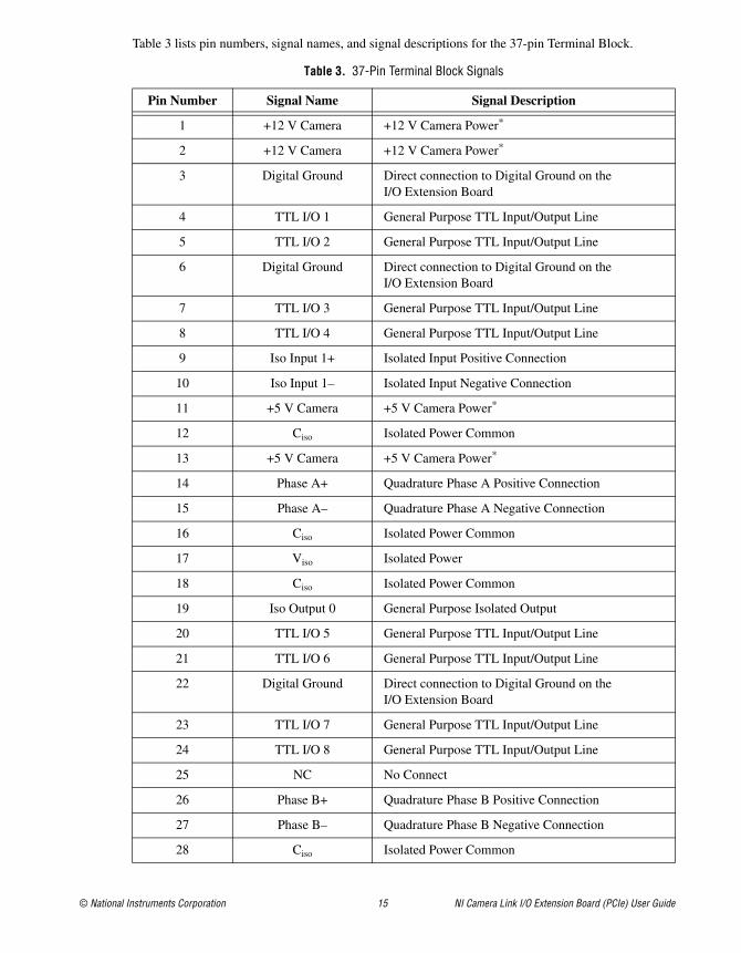
Table 3 lists pin numbers, signal names, and signal descriptions for the 37-pin Terminal Block.
Table 3. 37-Pin Terminal Block Signals
Pin Number Signal Name Signal Description
1 +12 V Camera +12 V Camera Power*
2 +12 V Camera +12 V Camera Power*
3 Digital Ground Direct connection to Digital Ground on the I/O Extension Board
4 TTL I/O 1 General Purpose TTL Input/Output Line
5 TTL I/O 2 General Purpose TTL Input/Output Line
6 Digital Ground Direct connection to Digital Ground on the I/O Extension Board
7 TTL I/O 3 General Purpose TTL Input/Output Line
8 TTL I/O 4 General Purpose TTL Input/Output Line
9 Iso Input 1+ Isolated Input Positive Connection
10 Iso Input 1– Isolated Input Negative Connection
11 +5 V Camera +5 V Camera Power*
12 Ciso Isolated Power Common
13 +5 V Camera +5 V Camera Power*
14 Phase A+ Quadrature Phase A Positive Connection
15 Phase A– Quadrature Phase A Negative Connection
16 Ciso Isolated Power Common
17 Viso Isolated Power
18 Ciso Isolated Power Common
19 Iso Output 0 General Purpose Isolated Output
20 TTL I/O 5 General Purpose TTL Input/Output Line
21 TTL I/O 6 General Purpose TTL Input/Output Line
22 Digital Ground Direct connection to Digital Ground on the I/O Extension Board
23 TTL I/O 7 General Purpose TTL Input/Output Line
24 TTL I/O 8 General Purpose TTL Input/Output Line
25 NC No Connect
26 Phase B+ Quadrature Phase B Positive Connection
27 Phase B– Quadrature Phase B Negative Connection
28 Ciso Isolated Power Common
NI Camera Link I/O Extension Board (PCIe) User Guide 16 ni.com
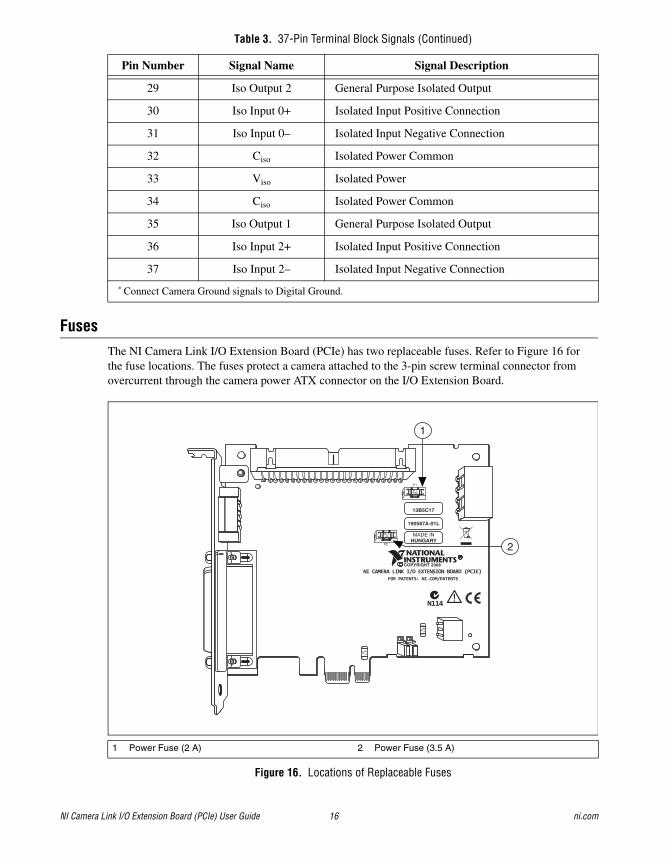
FusesThe NI Camera Link I/O Extension Board (PCIe) has two replaceable fuses. Refer to Figure 16 for the fuse locations. The fuses protect a camera attached to the 3-pin screw terminal connector from overcurrent through the camera power ATX connector on the I/O Extension Board.
Figure 16. Locations of Replaceable Fuses
29 Iso Output 2 General Purpose Isolated Output
30 Iso Input 0+ Isolated Input Positive Connection
31 Iso Input 0– Isolated Input Negative Connection
32 Ciso Isolated Power Common
33 Viso Isolated Power
34 Ciso Isolated Power Common
35 Iso Output 1 General Purpose Isolated Output
36 Iso Input 2+ Isolated Input Positive Connection
37 Iso Input 2– Isolated Input Negative Connection
* Connect Camera Ground signals to Digital Ground.
1 Power Fuse (2 A) 2 Power Fuse (3.5 A)
Table 3. 37-Pin Terminal Block Signals (Continued)
Pin Number Signal Name Signal Description
NI CAMERA LINK I/O EXTENSION BOARD (PCIE)
N114
FOR PATENTS: NI.COM/PATENTS
IE T2A
F1
F2
IE T
2A
IE T
2A
IE T3.5A
COPYRIGHT 2008
190587A-01L
MADE INHUNGARY
13B5C17
1
2

© National Instruments Corporation 17 NI Camera Link I/O Extension Board (PCIe) User Guide
Testing FusesYou can check the continuity of the fuse with a handheld DMM.
Replacing FusesTo replace a blown fuse on the I/O Extension Board, complete the following steps:
1. Disconnect the 50-pin ribbon cable from the I/O Extension board.
2. Disconnect the power connector from the camera power ATX connector.
3. Remove all signal wires and cables from the accessory.
4. Remove the device from the computer expansion slot.
5. Replace the blown fuse while referring to Figure 16 for the fuse location. You can order additional fuses from Littelfuse at www.littelfuse.com or from electronics distributors.
SpecificationsThe following specifications apply to the NI Camera Link I/O Extension Board (PCIe). All specifications are typical at 0 to 40 °C, unless otherwise stated.
TTL I/O
Caution TTL I/O lines provide no short-circuit protection. Failure to protect against short-circuit conditions will result in damage to the device.
Number of external TTL I/O lines .........................8
Trigger input
Voltage range .................................................0 V to 5 V (TTL)
Input high voltage ..................................2 V to 5 V
Input low voltage ...................................0 V to 0.8 V
Polarity...........................................................Programmable, active high or active low
Maximum pulse rate ......................................2 MHz
Minimum pulse detected................................250 ns
Trigger output
Voltage range .................................................0 V to 5 V (TTL)
Output high voltage................................2.4 V at 5 mA source
Output low voltage.................................0.55 V at 2 mA sink
Polarity...........................................................Programmable, active high or active low
Power-on state........................................................Input (high-impedance) 22 kΩ jumper selectable pull-up to 5 V, pull-down to digital ground, or tri-state
Fuse Littelfuse Part Number Description
Power fuse (2 A) 0452002.MRL or 0454002.MR
2 A, 125 V, NANO2 Slo-Blo Subminiature Surface Mount Fuse, 6.10 × 2.69 mm
Power fuse (3.5 A) 045203.5MRL or 045403.5MR
3.5 A, 125 V, NANO2 Slo-Blo Subminiature Surface Mount Fuse, 6.10 × 2.69 mm
NI Camera Link I/O Extension Board (PCIe) User Guide 18 ni.com
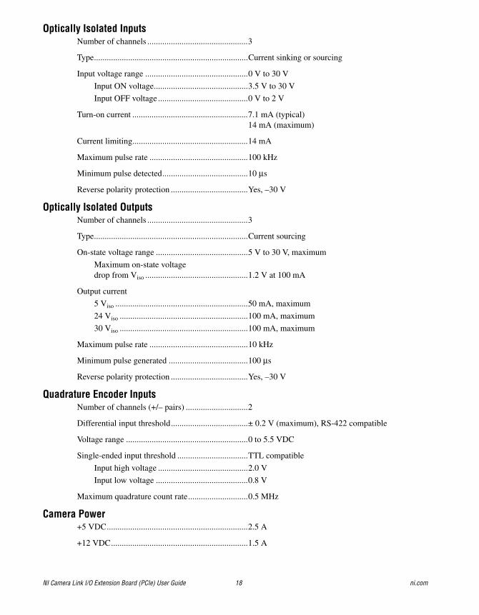
Optically Isolated InputsNumber of channels ...............................................3
Type........................................................................Current sinking or sourcing
Input voltage range ................................................0 V to 30 V
Input ON voltage............................................3.5 V to 30 V
Input OFF voltage ..........................................0 V to 2 V
Turn-on current ......................................................7.1 mA (typical)14 mA (maximum)
Current limiting......................................................14 mA
Maximum pulse rate ..............................................100 kHz
Minimum pulse detected........................................10 μs
Reverse polarity protection ....................................Yes, –30 V
Optically Isolated OutputsNumber of channels ...............................................3
Type........................................................................Current sourcing
On-state voltage range ...........................................5 V to 30 V, maximum
Maximum on-state voltage drop from Viso ................................................1.2 V at 100 mA
Output current
5 Viso ..............................................................50 mA, maximum
24 Viso ............................................................100 mA, maximum
30 Viso ............................................................100 mA, maximum
Maximum pulse rate ..............................................10 kHz
Minimum pulse generated .....................................100 μs
Reverse polarity protection ....................................Yes, –30 V
Quadrature Encoder InputsNumber of channels (+/– pairs) .............................2
Differential input threshold....................................± 0.2 V (maximum), RS-422 compatible
Voltage range .........................................................0 to 5.5 VDC
Single-ended input threshold .................................TTL compatible
Input high voltage ..........................................2.0 V
Input low voltage ...........................................0.8 V
Maximum quadrature count rate............................0.5 MHz
Camera Power+5 VDC..................................................................2.5 A
+12 VDC................................................................1.5 A
© National Instruments Corporation 19 NI Camera Link I/O Extension Board (PCIe) User Guide
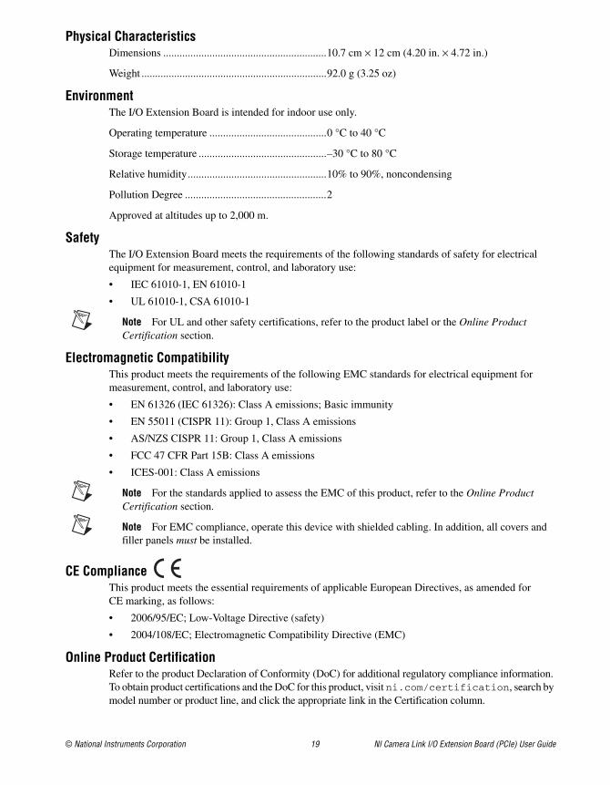
Physical CharacteristicsDimensions ............................................................10.7 cm × 12 cm (4.20 in. × 4.72 in.)
Weight ....................................................................92.0 g (3.25 oz)
EnvironmentThe I/O Extension Board is intended for indoor use only.
Operating temperature ...........................................0 °C to 40 °C
Storage temperature ...............................................–30 °C to 80 °C
Relative humidity...................................................10% to 90%, noncondensing
Pollution Degree ....................................................2
Approved at altitudes up to 2,000 m.
SafetyThe I/O Extension Board meets the requirements of the following standards of safety for electrical equipment for measurement, control, and laboratory use:
• IEC 61010-1, EN 61010-1
• UL 61010-1, CSA 61010-1
Note For UL and other safety certifications, refer to the product label or the Online Product Certification section.
Electromagnetic CompatibilityThis product meets the requirements of the following EMC standards for electrical equipment for measurement, control, and laboratory use:
• EN 61326 (IEC 61326): Class A emissions; Basic immunity
• EN 55011 (CISPR 11): Group 1, Class A emissions
• AS/NZS CISPR 11: Group 1, Class A emissions
• FCC 47 CFR Part 15B: Class A emissions
• ICES-001: Class A emissions
Note For the standards applied to assess the EMC of this product, refer to the Online Product Certification section.
Note For EMC compliance, operate this device with shielded cabling. In addition, all covers and filler panels must be installed.
CE ComplianceThis product meets the essential requirements of applicable European Directives, as amended for CE marking, as follows:
• 2006/95/EC; Low-Voltage Directive (safety)
• 2004/108/EC; Electromagnetic Compatibility Directive (EMC)
Online Product CertificationRefer to the product Declaration of Conformity (DoC) for additional regulatory compliance information. To obtain product certifications and the DoC for this product, visit ni.com/certification, search by model number or product line, and click the appropriate link in the Certification column.
National Instruments, NI, ni.com, and LabVIEW are trademarks of National Instruments Corporation. Refer to the Terms of Use section on ni.com/legal for more information about National Instruments trademarks. Other product and company names mentioned herein are trademarks or trade names of their respective companies. For patents covering National Instruments products/technology, refer to the appropriate location: Help»Patents in your software, the patents.txt file on your media, or the National Instruments Patent Notice at ni.com/patents.
© 2009 National Instruments Corporation. All rights reserved. 372736B-01 Apr09
Environmental ManagementNational Instruments is committed to designing and manufacturing products in an environmentally responsible manner. NI recognizes that eliminating certain hazardous substances from our products is beneficial not only to the environment but also to NI customers.
For additional environmental information, refer to the NI and the Environment Web page at ni.com/environment. This page contains the environmental regulations and directives with which NI complies, as well as other environmental information not included in this document.
Waste Electrical and Electronic Equipment (WEEE)EU Customers At the end of their life cycle, all products must be sent to a WEEE recycling center. For more information about WEEE recycling centers and National Instruments WEEE initiatives, visit ni.com/environment/weee.htm.
Where to Go for SupportThe National Instruments Web site is your complete resource for technical support. At ni.com/support you have access to everything from troubleshooting and application development self-help resources to email and phone assistance from NI Application Engineers.
A Declaration of Conformity (DoC) is our claim of compliance with the Council of the European Communities using the manufacturer’s declaration of conformity. This system affords the user protection for electronic compatibility (EMC) and product safety. You can obtain the DoC for your product by visiting ni.com/certification. If your product supports calibration, you can obtain the calibration certificate for your product at ni.com/calibration.
National Instruments corporate headquarters is located at 11500 North Mopac Expressway, Austin, Texas, 78759-3504. National Instruments also has offices located around the world to help address your support needs. For telephone support in the United States, create your service request at ni.com/support and follow the calling instructions or dial 512 795 8248. For telephone support outside the United States, contact your local branch office:
Australia 1800 300 800, Austria 43 662 457990-0, Belgium 32 (0) 2 757 0020, Brazil 55 11 3262 3599, Canada 800 433 3488, China 86 21 5050 9800, Czech Republic 420 224 235 774, Denmark 45 45 76 26 00, Finland 358 (0) 9 725 72511, France 01 57 66 24 24, Germany 49 89 7413130, India 91 80 41190000, Israel 972 3 6393737, Italy 39 02 41309277, Japan 0120-527196, Korea 82 02 3451 3400, Lebanon 961 (0) 1 33 28 28, Malaysia 1800 887710, Mexico 01 800 010 0793, Netherlands 31 (0) 348 433 466, New Zealand 0800 553 322, Norway 47 (0) 66 90 76 60, Poland 48 22 328 90 10, Portugal 351 210 311 210, Russia 7 495 783 6851, Singapore 1800 226 5886, Slovenia 386 3 425 42 00, South Africa 27 0 11 805 8197, Spain 34 91 640 0085, Sweden 46 (0) 8 587 895 00, Switzerland 41 56 2005151, Taiwan 886 02 2377 2222, Thailand 662 278 6777, Turkey 90 212 279 3031, United Kingdom 44 (0) 1635 523545
RoHSNational Instruments (RoHS)
National Instruments RoHS ni.com/environment/rohs_china(For information about China RoHS compliance, go to ni.com/environment/rohs_china.)


