Download - Noble Denton 0027
GUIDELINES FOR LIFTING OPERATIONS BY FLOATING CRANE VESSELS
No: 0027/NDI
16.02.06 5 RLJ Technical Policy Board
30.11.05 4 JR Technical Policy Board
15.10.02 3 JR Technical Policy Board
01.05.02 2 JR Technical Policy Board
11.08.93 1 JR Technical Policy Board
31.10.90 0 JR Technical Policy Board
Date Rev. Prepared by Authorised by
0027/NDI REV 5
0027/NDI Page 2
PREFACE This document has been drawn with care to address what are likely to be the main concerns based on the experience of the Noble Denton organisation. This should not, however, be taken to mean that this document deals comprehensively with all of the concerns which will need to be addressed or even, where a particular matter is addressed, that this document sets out the definitive view of the organisation for all situations. In using this document, it should be treated as giving guidelines for sound and prudent practice on which our advice should be based, but these guidelines should be reviewed in each particular case by the responsible person in each project to ensure that the particular circumstances of that project are addressed in a way which is adequate and appropriate to ensure that the overall advice given is sound and comprehensive.
0027/NDI REV 5
0027/NDI Page 3
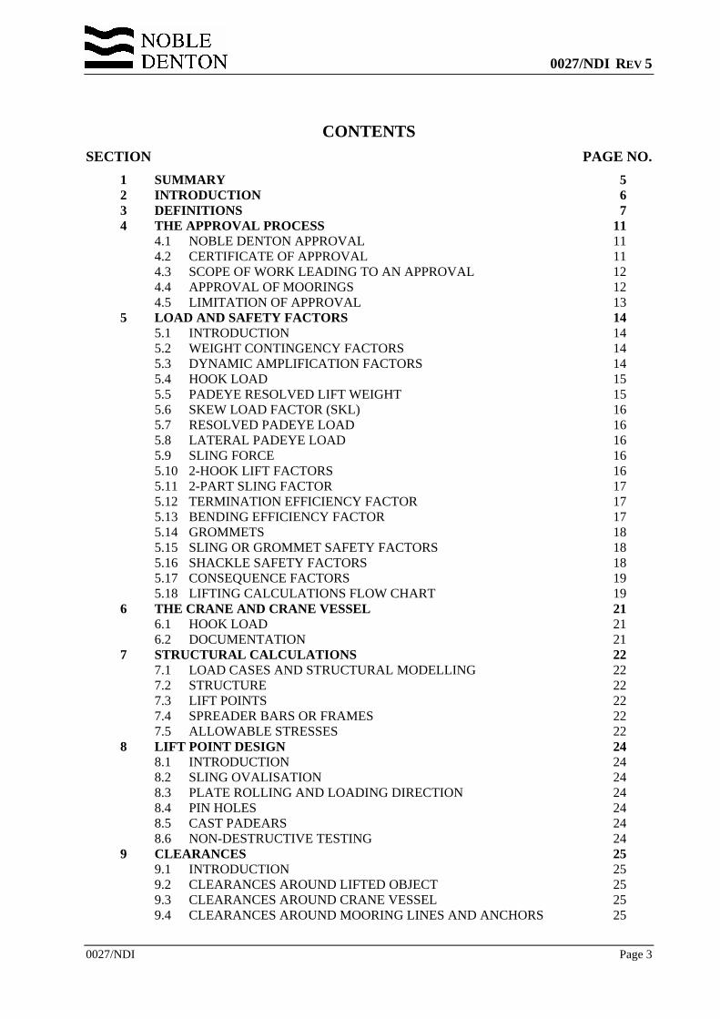
CONTENTS SECTION PAGE NO.
1 SUMMARY 5 2 INTRODUCTION 6 3 DEFINITIONS 7 4 THE APPROVAL PROCESS 11
4.1 NOBLE DENTON APPROVAL 11 4.2 CERTIFICATE OF APPROVAL 11 4.3 SCOPE OF WORK LEADING TO AN APPROVAL 12 4.4 APPROVAL OF MOORINGS 12 4.5 LIMITATION OF APPROVAL 13
5 LOAD AND SAFETY FACTORS 14 5.1 INTRODUCTION 14 5.2 WEIGHT CONTINGENCY FACTORS 14 5.3 DYNAMIC AMPLIFICATION FACTORS 14 5.4 HOOK LOAD 15 5.5 PADEYE RESOLVED LIFT WEIGHT 15 5.6 SKEW LOAD FACTOR (SKL) 16 5.7 RESOLVED PADEYE LOAD 16 5.8 LATERAL PADEYE LOAD 16 5.9 SLING FORCE 16 5.10 2-HOOK LIFT FACTORS 16 5.11 2-PART SLING FACTOR 17 5.12 TERMINATION EFFICIENCY FACTOR 17 5.13 BENDING EFFICIENCY FACTOR 17 5.14 GROMMETS 18 5.15 SLING OR GROMMET SAFETY FACTORS 18 5.16 SHACKLE SAFETY FACTORS 18 5.17 CONSEQUENCE FACTORS 19 5.18 LIFTING CALCULATIONS FLOW CHART 19
6 THE CRANE AND CRANE VESSEL 21 6.1 HOOK LOAD 21 6.2 DOCUMENTATION 21
7 STRUCTURAL CALCULATIONS 22 7.1 LOAD CASES AND STRUCTURAL MODELLING 22 7.2 STRUCTURE 22 7.3 LIFT POINTS 22 7.4 SPREADER BARS OR FRAMES 22 7.5 ALLOWABLE STRESSES 22
8 LIFT POINT DESIGN 24 8.1 INTRODUCTION 24 8.2 SLING OVALISATION 24 8.3 PLATE ROLLING AND LOADING DIRECTION 24 8.4 PIN HOLES 24 8.5 CAST PADEARS 24 8.6 NON-DESTRUCTIVE TESTING 24
9 CLEARANCES 25 9.1 INTRODUCTION 25 9.2 CLEARANCES AROUND LIFTED OBJECT 25 9.3 CLEARANCES AROUND CRANE VESSEL 25 9.4 CLEARANCES AROUND MOORING LINES AND ANCHORS 25
0027/NDI REV 5
0027/NDI Page 4
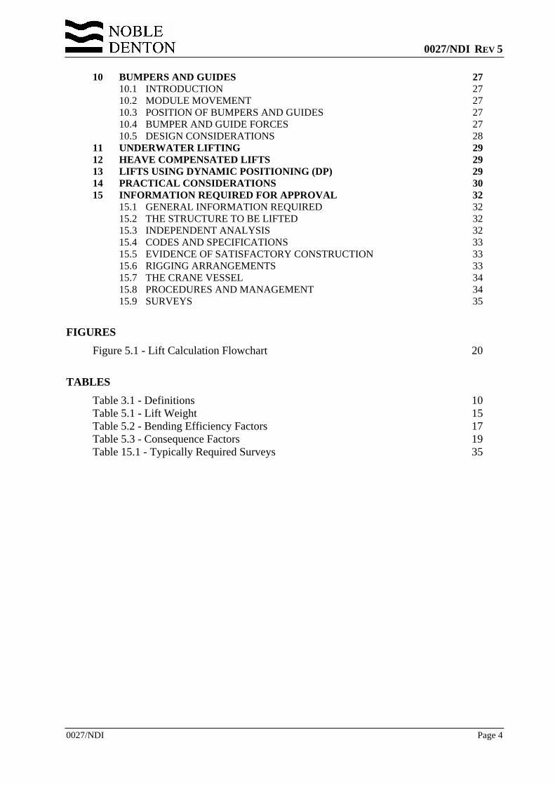
10 BUMPERS AND GUIDES 27 10.1 INTRODUCTION 27 10.2 MODULE MOVEMENT 27 10.3 POSITION OF BUMPERS AND GUIDES 27 10.4 BUMPER AND GUIDE FORCES 27 10.5 DESIGN CONSIDERATIONS 28
11 UNDERWATER LIFTING 29 12 HEAVE COMPENSATED LIFTS 29 13 LIFTS USING DYNAMIC POSITIONING (DP) 29 14 PRACTICAL CONSIDERATIONS 30 15 INFORMATION REQUIRED FOR APPROVAL 32
15.1 GENERAL INFORMATION REQUIRED 32 15.2 THE STRUCTURE TO BE LIFTED 32 15.3 INDEPENDENT ANALYSIS 32 15.4 CODES AND SPECIFICATIONS 33 15.5 EVIDENCE OF SATISFACTORY CONSTRUCTION 33 15.6 RIGGING ARRANGEMENTS 33 15.7 THE CRANE VESSEL 34 15.8 PROCEDURES AND MANAGEMENT 34 15.9 SURVEYS 35
FIGURES Figure 5.1 - Lift Calculation Flowchart 20
TABLES Table 3.1 - Definitions 10 Table 5.1 - Lift Weight 15 Table 5.2 - Bending Efficiency Factors 17 Table 5.3 - Consequence Factors 19 Table 15.1 - Typically Required Surveys 35
0027/NDI REV 5
0027/NDI Page 5
1 SUMMARY 1.1 This Report provides guidelines on which the design and approval of marine lifting
operations may be based.
1.2 This document supersedes the previous revision, document No. 0027/NDI Rev 3 dated 15th October 2002. A summary of the principal changes is given in Section 2.7.
1.3 These guidelines cover lifting operations by floating crane vessels, including crane barges, crane ships and semi-submersible crane vessels. They may also be applied to lifting operations by land-based cranes for the purpose of loadout. They are intended to lead to an approval by Noble Denton, which may be required where an operation is the subject of an insurance warranty, or where an independent third party review is required.
1.4 A description of the approval process is given for those projects which are the subject of an insurance warranty.
1.5 The report includes guidelines for the load and safety factors to be applied at the design stage.
1.6 Comments on the practical aspects of the management of the operation are also offered.
0027/NDI REV 5
0027/NDI Page 6
2 INTRODUCTION 2.1 This report provides guidelines on which the design and approval of marine lifting
operations may be based.
2.2 It covers lifting operations by floating crane vessels, including crane barges, crane ships and semi-submersible crane vessels. It refers to lifting operations inshore and offshore. Reference is also made to lifting operations by land-based cranes for the purpose of loadout onto a barge or other transportation vessel.
2.3 The guidelines and calculation methods set out in this report represent the views of Noble Denton and are considered to be sound and in accordance with offshore industry practice. Operators should also consider national and local regulations, which may be more stringent.
2.4 The Report includes guidelines for the safety factors to be applied, comments on safe rigging practice and the information and documentation to be produced by others in order to obtain Noble Denton approval.
2.5 Revision 2 superseded and replaced the previous version, Revision dated 11th August 1993. Principal changes in Revision 2 included:
• Reference to the ISO Draft Standard on weight control • Reserves specified on weights as calculated or measured according to the
ISO/DIS • Limitations of Noble Denton Approval clarified • Changes to the required clearances on pipelines and other subsea assets • Addition to a section on heave-compensated lifts • Addition of a section on lifts using Dynamic Positioning.
2.6 Revision 3 superseded and replaced Revision 2, and includes additional clarification on safety factors for shackles, and testing and certification requirements.
2.7 Revision 4 superseded and replaced Revision 3, and includes;
• Changes to referenced documents (Sections 2.8 and References) • Some changes to definitions (Section 3) • Changes to Dynamic Amplification Factors, to eliminate discontinuities
(Section 5.3) • Elimination of an anomaly in the definition of Hook Load (Section 5.3) • Inclusion of consideration of fibre slings (Sections 5.11, 5.14 and 15) • Elimination of an anomaly in the treatment of spreader bars and frames
(Sections 5.16 and 7.4) • Modification of the flow chart (Section 5.17) • Changes to the derivation of bumper and guide design forces (Section 10.3).
2.8 This further Revision 5 supersedes and replaces Revision 4, and corrects a typographical error in Table 5.1.
2.9 The Report refers as appropriate to other standards, including Noble Denton Report 0013/NDI (Reference 1), ISO 19901-5:2003 (Reference 2) and International Marine Contractors Association Guidance Document IMCA M 179 (Reference 3).
0027/NDI REV 5
0027/NDI Page 7
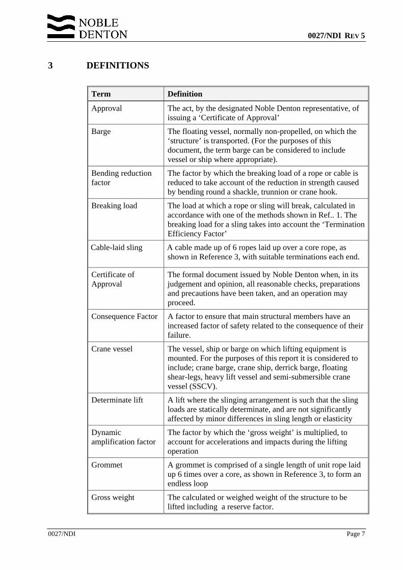
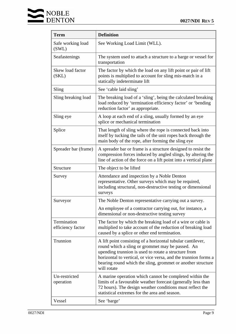
3 DEFINITIONS
Term Definition
Approval The act, by the designated Noble Denton representative, of issuing a ‘Certificate of Approval’
Barge The floating vessel, normally non-propelled, on which the ‘structure’ is transported. (For the purposes of this document, the term barge can be considered to include vessel or ship where appropriate).
Bending reduction factor
The factor by which the breaking load of a rope or cable is reduced to take account of the reduction in strength caused by bending round a shackle, trunnion or crane hook.
Breaking load
The load at which a rope or sling will break, calculated in accordance with one of the methods shown in Ref.. 1. The breaking load for a sling takes into account the ‘Termination Efficiency Factor’
Cable-laid sling
A cable made up of 6 ropes laid up over a core rope, as shown in Reference 3, with suitable terminations each end.
Certificate of Approval
The formal document issued by Noble Denton when, in its judgement and opinion, all reasonable checks, preparations and precautions have been taken, and an operation may proceed.
Consequence Factor A factor to ensure that main structural members have an increased factor of safety related to the consequence of their failure.
Crane vessel The vessel, ship or barge on which lifting equipment is mounted. For the purposes of this report it is considered to include; crane barge, crane ship, derrick barge, floating shear-legs, heavy lift vessel and semi-submersible crane vessel (SSCV).
Determinate lift
A lift where the slinging arrangement is such that the sling loads are statically determinate, and are not significantly affected by minor differences in sling length or elasticity
Dynamic amplification factor
The factor by which the ‘gross weight’ is multiplied, to account for accelerations and impacts during the lifting operation
Grommet A grommet is comprised of a single length of unit rope laid up 6 times over a core, as shown in Reference 3, to form an endless loop
Gross weight The calculated or weighed weight of the structure to be lifted including a reserve factor.
0027/NDI REV 5
0027/NDI Page 8
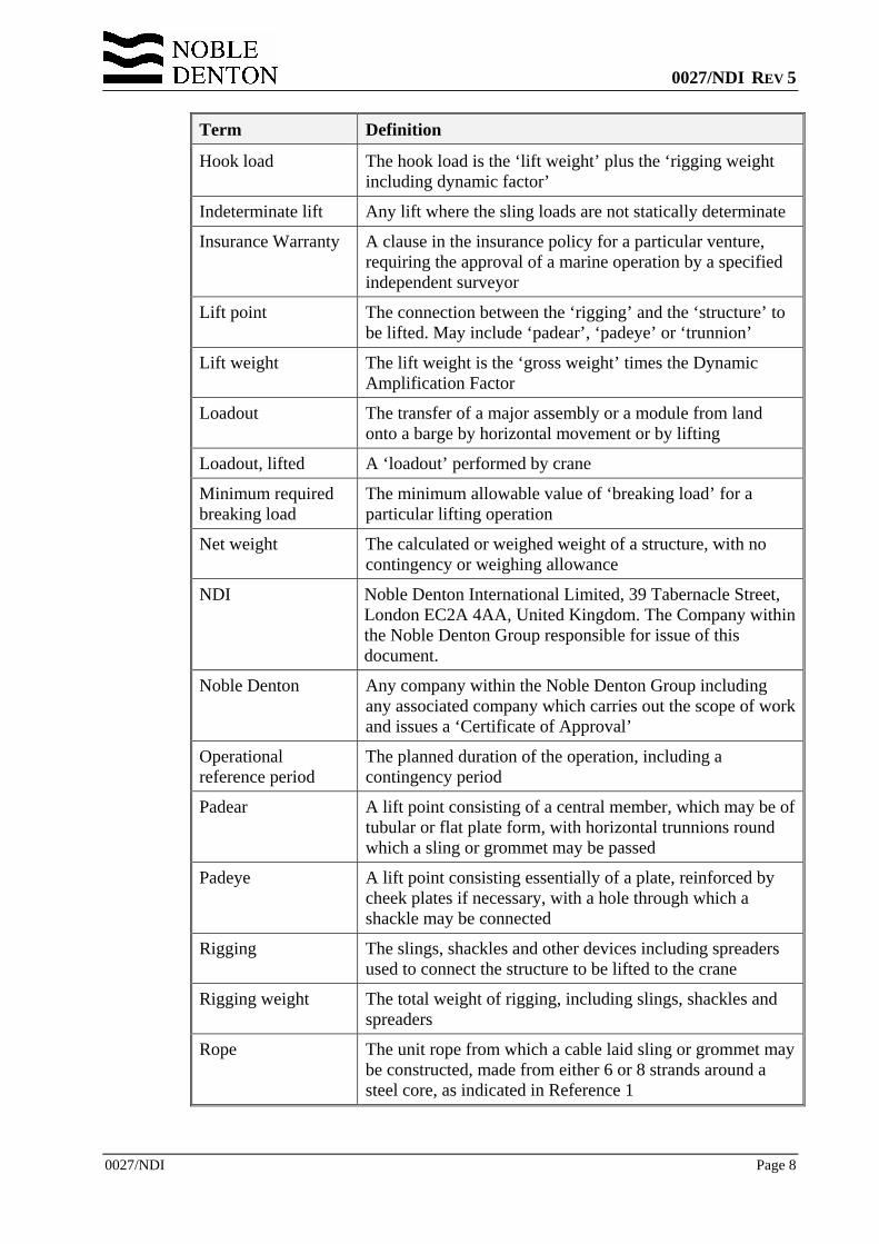
Term Definition
Hook load The hook load is the ‘lift weight’ plus the ‘rigging weight including dynamic factor’
Indeterminate lift Any lift where the sling loads are not statically determinate
Insurance Warranty A clause in the insurance policy for a particular venture, requiring the approval of a marine operation by a specified independent surveyor
Lift point The connection between the ‘rigging’ and the ‘structure’ to be lifted. May include ‘padear’, ‘padeye’ or ‘trunnion’
Lift weight The lift weight is the ‘gross weight’ times the Dynamic Amplification Factor
Loadout The transfer of a major assembly or a module from land onto a barge by horizontal movement or by lifting
Loadout, lifted A ‘loadout’ performed by crane
Minimum required breaking load
The minimum allowable value of ‘breaking load’ for a particular lifting operation
Net weight The calculated or weighed weight of a structure, with no contingency or weighing allowance
NDI Noble Denton International Limited, 39 Tabernacle Street, London EC2A 4AA, United Kingdom. The Company within the Noble Denton Group responsible for issue of this document.
Noble Denton Any company within the Noble Denton Group including any associated company which carries out the scope of work and issues a ‘Certificate of Approval’
Operational reference period
The planned duration of the operation, including a contingency period
Padear A lift point consisting of a central member, which may be of tubular or flat plate form, with horizontal trunnions round which a sling or grommet may be passed
Padeye A lift point consisting essentially of a plate, reinforced by cheek plates if necessary, with a hole through which a shackle may be connected
Rigging The slings, shackles and other devices including spreaders used to connect the structure to be lifted to the crane
Rigging weight The total weight of rigging, including slings, shackles and spreaders
Rope The unit rope from which a cable laid sling or grommet may be constructed, made from either 6 or 8 strands around a steel core, as indicated in Reference 1
0027/NDI REV 5
0027/NDI Page 9
Term Definition
Safe working load (SWL)
See Working Load Limit (WLL).
Seafastenings The system used to attach a structure to a barge or vessel for transportation
Skew load factor (SKL)
The factor by which the load on any lift point or pair of lift points is multiplied to account for sling mis-match in a statically indeterminate lift
Sling See ‘cable laid sling’
Sling breaking load The breaking load of a ‘sling’, being the calculated breaking load reduced by ‘termination efficiency factor’ or ‘bending reduction factor’ as appropriate.
Sling eye A loop at each end of a sling, usually formed by an eye splice or mechanical termination
Splice That length of sling where the rope is connected back into itself by tucking the tails of the unit ropes back through the main body of the rope, after forming the sling eye
Spreader bar (frame) A spreader bar or frame is a structure designed to resist the compression forces induced by angled slings, by altering the line of action of the force on a lift point into a vertical plane
Structure The object to be lifted
Survey Attendance and inspection by a Noble Denton representative. Other surveys which may be required, including structural, non-destructive testing or dimensional surveys
Surveyor The Noble Denton representative carrying out a survey.
An employee of a contractor carrying out, for instance, a dimensional or non-destructive testing survey
Termination efficiency factor
The factor by which the breaking load of a wire or cable is multiplied to take account of the reduction of breaking load caused by a splice or other end termination.
Trunnion A lift point consisting of a horizontal tubular cantilever, round which a sling or grommet may be passed. An upending trunnion is used to rotate a structure from horizontal to vertical, or vice versa, and the trunnion forms a bearing round which the sling, grommet or another structure will rotate
Un-restricted operation
A marine operation which cannot be completed within the limits of a favourable weather forecast (generally less than 72 hours). The design weather conditions must reflect the statistical extremes for the area and season.
Vessel See ‘barge’
0027/NDI REV 5
0027/NDI Page 10
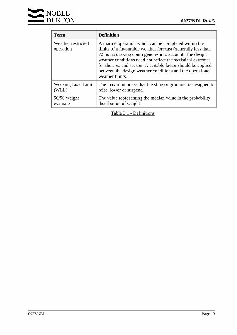
Term Definition
Weather restricted operation
A marine operation which can be completed within the limits of a favourable weather forecast (generally less than 72 hours), taking contingencies into account. The design weather conditions need not reflect the statistical extremes for the area and season. A suitable factor should be applied between the design weather conditions and the operational weather limits.
Working Load Limit (WLL)
The maximum mass that the sling or grommet is designed to raise, lower or suspend
50/50 weight estimate
The value representing the median value in the probability distribution of weight
Table 3.1 - Definitions
0027/NDI REV 5
0027/NDI Page 11
4 THE APPROVAL PROCESS
4.1 NOBLE DENTON APPROVAL 4.1.1 Noble Denton approval may be sought where the lift forms part of a marine
operation covered by an insurance warranty, or where an independent third party review is required.
4.1.2 An Insurance Warranty is a clause in the insurance policy for a particular venture, requiring the approval of a marine operation by a specified independent surveyor. The requirement is normally satisfied by the issue of a Certificate of Approval. Responsibility for interpreting the terms of the Warranty so that an appropriate scope of work can be defined rests with the client.
4.1.3 Approval may be given for such operations as;
• Installation of liftable jackets • Hook-assisted installation of launched jackets • Installation of templates and other sub-sea equipment • Handling of piles • Installation of decks, topsides modules, bridges and flare towers • Shore to barge loadouts • Transfer of items from a transport barge to the deck of an SSCV.
4.1.4 Lifts may be by a variety of crane configurations, including single cranes, two cranes on a single vessel, two or more cranes on separate vessels, single crane multi-hook sheerleg vessels, or by one or more land based cranes.
4.1.5 Noble Denton approval may be given for the operation, including reviews of marine and engineering calculations and procedures, and consideration of;
• The actual and forecast weather conditions • The suitability and readiness of all equipment • The behaviour of the lifting vessel • Any site changes in procedures • The general conduct of the preparations for the operation.
4.2 CERTIFICATE OF APPROVAL 4.2.1 The deliverable of the approval process will generally be a Certificate of Approval.
This will be issued on site, immediately prior to the lift taking place.
4.2.2 For an offshore lift, the Certificate will normally be issued prior to cutting the seafastenings on the transport barge or vessel, and the lifting operation will be deemed to have commenced when seafastening cutting starts. The lift will be deemed to be completed when the load is landed in its final position, and the crane has been disconnected.
0027/NDI REV 5
0027/NDI Page 12
4.3 SCOPE OF WORK LEADING TO AN APPROVAL 4.3.1 In order to issue a Certificate of Approval, Noble Denton will require to consider the
following topics;
• The strength of the structure to be lifted, including the strength of the lift points.
• The capacity of the crane, taking into account the radius at which the lift will take place, whether the crane will be fixed or revolving and whether any downrating is required for operations in a specified seastate.
• The rigging arrangement, including slings, shackles and any spreader frames or beams, and the certification of the rigging components.
• The mooring arrangements for the crane vessel, as outlined in Section 4.5. • The limiting weather conditions proposed, and the anticipated behaviour of
the crane vessel in those conditions. • The arrangements for handling and mooring the transport barge or vessel
alongside the crane vessel. • The arrangements for cutting seafastenings prior to lifting. • The management structure for the operation.
4.3.2 The information required in order to issue a Certificate of Approval is discussed in more detail in Section 15.
4.4 APPROVAL OF MOORINGS 4.4.1 A lift may normally be considered a weather restricted operation. Limiting weather
conditions for the lift operation shall be defined, taking into account;
• the forecast reliability for the area • the duration of the operation, including a suitability contingency period • the exposure of the site • the time required for any operations before or after the lift operation,
including crane vessel and transport barge movements. • currents during the lift.
4.4.2 An approval of a lift will normally include the approval of the crane vessel and transport barge moorings in the limiting weather conditions specified for the lifting operation. When operating alongside an offshore installation, procedures should be submitted which show that the crane vessel and transport barge can and will be removed to a safe distance when the weather conditions exceed a specified level. An approval of a lift does not include approval of the vessel moorings in extreme weather conditions.
4.4.3 Similarly, an approval of a lifted loadout will include the approval of the crane vessel and transport barge moorings at the loadout quay in the limiting weather conditions specified for loadout. It does not necessarily include approval of either moorings in extreme weather conditions. Note that for approval of loadouts, reference should also be made to Noble Denton Report 0013/NDI - Guidelines for loadouts (Reference 1).
4.4.4 Additionally, and if specifically requested, Noble Denton will study and issue an approval of the moorings of the crane vessel or the transport barge, for a more extended period.
0027/NDI REV 5
0027/NDI Page 13
4.5 LIMITATION OF APPROVAL 4.5.1 A Certificate of Approval is issued for a particular lift only.
4.5.2 A Certificate of Approval is issued based on external conditions observed by the attending surveyor of hull(s) machinery and equipment, without removal, exposure or testing of parts.
4.5.3 A Certificate of Approval for a lift covers the marine operations involved in the lift only. A lift is normally deemed to start offshore when cutting of seafastenings starts, and inshore/onshore when the crane is connected and slings tensioned. It is normally deemed to be completed when the lifted object is set down in its intended position. For completion of lifted loadouts, refer to Reference 1.
4.5.4 Unless specifically included, a Certificate of Approval for a lift excludes moorings of the crane vessel and transport barge outside the period of the immediate lift, as defined in Section 4.4.1.
4.5.5 Any alterations to the surveyed items or agreed procedures after issue of the Certificate of Approval may render the Certificate invalid unless the changes are approved by Noble Denton.
0027/NDI REV 5
0027/NDI Page 14
5 LOAD AND SAFETY FACTORS
5.1 INTRODUCTION 5.1.1 For any lift, the calculations carried out shall include the following allowances,
factors and loads or equivalent.
5.2 WEIGHT CONTINGENCY FACTORS 5.2.1 Weight control shall be performed by means of a well defined, documented system,
in accordance with current good practice, such as ISO International Standard ISO 19901-5:2003 – Petroleum and natural gas industries – specific requirements for offshore structures – Part 5: Weight control during engineering and construction (Reference 2).
5.2.2 In relation to weight control classes, Reference 2 states (inter alia) that;
• “Class A shall apply if the project is weight or CoG-sensitive for lifting and marine operations or during operation (with the addition of temporaries) or has many contractors with which to interface. Project may also require this high definition if risk gives cause for concern”.
• “Class B weight control definition shall apply to projects where the focus on weight and CoG is less critical for lifting and marine operations”.
• “Class C weight control definition shall apply to projects where the requirement for weight and CoG data are not critical”.
5.2.3 Unless it can be shown that a particular structure and specific lift operation are not weight or sensitive, then Class A weight control definition will be needed, as shown in Reference 2, Section 4.2. If the 50/50 weight estimate as defined in Reference 2 is derived, then an appropriate factor, which shall be not less than 1.05, shall be applied. The extremes of the CoG envelope shall be used.
5.2.4 A factor of not less than 1.03 shall generally be applied to the final weighed weight. This may be reduced if a Certificate is produced from a Competent Body stating, for the specific case in question, that the weighing accuracy is better than 3%. The reserve factor shall never be less than 1.01.
Gross weight (Wg) = (calculated or weighed weight) x (reserve factor)
5.3 DYNAMIC AMPLIFICATION FACTORS 5.3.1 Unless operation-specific calculations show otherwise, for lifts by a single crane, Lift
Weight (Wl) shall be derived from Table 5.1.
0027/NDI REV 5
0027/NDI Page 15
Lift weight, Wl tonnes
Onshore Gross weight, Wg
(tonnes) Offshore Inshore Moving Static
Wg ≤100 1.30 x Wg 1.15 x Wg Wg
100 < Wg < 1000 130 + 1.1889 x (Wg - 100) 115 + 1.094 x (Wg - 100) Wg
1,000 < Wg ≤ 2,500 1,200 + 1.1167 x (Wg - 1,000) 1,100 + 1.0167 x (Wg - 1,000) Wg
2,500 < Wg < 10,000 2,875 + 1.0833 x (Wg - 2,500) 1.05 x Wg Wg
Wg > 10,000 1.10 x Wg 1.05 x Wg Wg
Table 5.1 - Lift Weight
5.3.2 Dynamic Amplification Factor (DAF) = Wl/Wg.
5.3.3 Alternatively, the DAF may be derived from a suitable calculation or model test. Where the lift is from or onto a barge or vessel alongside the crane vessel, then the barge or vessel motions must be taken into account as well as the crane boom-tip motions.
5.3.4 Where a limiting design sea state is derived by calculation or model tests, the limiting operational seastate shall not exceed (0.7 x the limiting design seastate)
5.3.5 For offshore lifts by 2 or more vessels, the lift weight as computed above shall be multiplied by a further DAF of 1.1.
5.3.6 For inshore lifts, in totally sheltered waters, by 2 or more vessels, the factors indicated by in Table 5.1 shall apply, with no further DAF for the multiple vessel condition.
5.3.7 For onshore lifts by 2 or more cranes, the factors indicated by Table 5.1 shall apply, with no further DAF for the multiple crane condition.
5.3.8 For onshore lifts, where the crane(s) may move horizontally, the “Moving” column Table 5.1 shall apply. The “Static” column shall only apply if there is no crane movement other than lifting, lowering or slewing.
5.4 HOOK LOAD 5.4.1 In general, when considering the loading on a padeye or the structure, the lift weight
as defined above should be used. Loads in slings, and the total loading on the crane should be based on hook load, where;
Hook load = (lift weight) + (rigging weight x DAF)
5.4.2 Rigging weight includes all items between the padeyes and the crane hook, including slings, shackles and spreaders as appropriate.
5.4.3 Note; throughout Section5, the term "padeye" is taken, for simplicity, to include any type of lift point, including padear, trunnion or other type.
5.5 PADEYE RESOLVED LIFT WEIGHT 5.5.1 The padeye resolved lift weight is the vertical load at each padeye, taking into
account lift weight and centre of gravity only.
0027/NDI REV 5
0027/NDI Page 16
5.5.2 Where the allowable centre of gravity position is specified as a cruciform or other geometric shape, then the most conservative centre of gravity position within the allowable area should be taken.
5.6 SKEW LOAD FACTOR (SKL) 5.6.1 For indeterminate 4-sling lifts using matched pairs of slings, a skew load factor
(SKL) of 1.25 shall be applied to each diagonally opposite pair of lift points in turn. For determinate lifts the SKL may be taken to be 1.0, provided it can be demonstrated that sling length errors do not significantly affect the load attitude or lift system geometry. The length permitted tolerance on matched pairs of slings is defined according to Reference 3.
Vertical padeye load = (padeye resolved lift weight) x SKL
5.7 RESOLVED PADEYE LOAD 5.7.1 The resolved padeye load is the vertical padeye load divided by the sine of the sling
angle;
Resolved padeye load = (vertical padeye load) Sin (sling angle)
where the sling angle is the angle between the sling and the horizontal plane.
5.8 LATERAL PADEYE LOAD 5.8.1 Provided the lift-point is correctly orientated with the sling direction, then a
horizontal force equal to 5% of the resolved padeye load shall be applied, acting through the centreline and along the axis of the pin-hole or trunnion.
5.8.2 If the lift point is not correctly orientated with the sling direction, then the computed force acting along the axis of the pin-hole or trunnion plus 5% of the resolved padeye load shall be applied.
5.9 SLING FORCE 5.9.1 The sling force is the vertical padeye load plus the sling weight (per sling) divided by
the sine of the sling angle. The DAF as derived from Section 5.3 should be applied to the sling weight;
Sling force = (vertical padeye load) + (sling weight x DAF) Sin (sling angle)
5.10 2-HOOK LIFT FACTORS 5.10.1 For a 2-hook lift, the resolved lift weight at each hook shall be multiplied by the
following factors;
Centre of gravity factor = 1.03
Tilt factor = 1.03
Hook resolved lift weight = (statically resolved lift weight at each hook) x (centre of gravity factor) x (tilt factor)
0027/NDI REV 5
0027/NDI Page 17
For a 2-hook lift, with 2 slings to each hook, the load resolved to each padeye shall be multiplied by a yaw factor;
Yaw Factor = 1.00 (Onshore Lifts)
Yaw factor = 1.05 (Offshore Lifts)
Padeye resolved lift weight =
(hook resolved lift weight, resolved to each padeye) x (yaw factor)
5.10.2 2-hook lifts with other rigging arrangements will require special consideration.
5.11 2-PART SLING FACTOR 5.11.1 Where a 2-part sling or grommet passes over, round or through a shackle, trunnion,
padear or crane hook, other than at a termination, the total sling force shall be distributed into each part in the ratio 45:55.
Sling load = sling force x 0.55
5.12 TERMINATION EFFICIENCY FACTOR 5.12.1 The breaking load of a sling ending in an eye splice shall be assumed to be the
calculated rope breaking load multiplied by a factor as follows;
• For hand splices, including fibre slings; 0.75
• For resin sockets; 1.00
• Swage fittings, eg “Superloop”; 1.00
• Other methods of termination will require special consideration.
Sling breaking load = (rope breaking load) x (termination efficiency factor)
5.12.2 It is not recommended that a sling eye is bent round a diameter less than the sling diameter. Bending in way of splices shall be avoided.
5.13 BENDING EFFICIENCY FACTOR 5.13.1 Where any wire rope sling or grommet is bent round a shackle, trunnion, padear or
crane hook, the breaking load shall be assumed to be the calculated breaking load multiplied by a bending efficiency factor;
Bending efficiency factor = 1 - 0.5/√( D/d),
where; d = the sling or cable laid rope diameter
D = the minimum diameter over which the sling body, grommet end or body is bent.
5.13.2 For wire rope slings and grommets, this results in the bending efficiency factors detailed in Table 5.2
D/d <0.8 0.8 0.9 1.0 1.5 2.0 3.0 4.0 5.0
Factor Not Adv’d 0.44 0.47 0.50 0.59 0.65 0.71 0.75 0.78
Table 5.2 - Bending Efficiency Factors
Sling breaking load = (calculated breaking load) x (bending efficiency factor)
0027/NDI REV 5
0027/NDI Page 18
5.13.3 For fibre rope slings, the bending efficiency may normally be taken as 1.00, provided the bending diameter is not less than the minimum specified by the manufacturer.
5.13.4 It should be noted that termination and bending factors should not be applied simultaneously. The one which results in the lower value of breaking load will govern, and should be used.
5.13.5 Under no circumstances should the sling or grommet body contact any surface where the radius is less than 0.5d.
5.14 GROMMETS 5.14.1 Grommets require special consideration, to ensure that the rope breaking load and
bending efficiency have been correctly taken into account. It is assumed that grommets are constructed and used in accordance with IMCA M 179 (Reference 3).
5.14.2 The load in a grommet shall be distributed into each part in the ratio 45:55, as indicated by Section 5.11.
5.14.3 The core of a grommet should be discounted when computing breaking load. The breaking load of each part of a grommet is therefore usually taken as 6 times the unit rope breaking load, with a factor to account for the spinning losses in cabling. This factor is normally taken as 0.85.
Grommet BL (each part) = 0.85 x 6 x breaking load of unit rope 5.14.4 Typically, a grommet will be used with one end over the crane hook, and the other
end connected to a padeye by a shackle. The bending efficiency factors at each end may differ, and the more severe value should be taken. Bending efficiency is derived as in Section 5.12.1, where rope diameter is the single part grommet diameter. The total breaking load of the grommet used in this manner is;
2 x (single part grommet BL) x (more severe bending efficiency factor)
5.14.5 Bending in way of grommet butt connections shall be avoided. The location of the butt connection shall be marked.
5.15 SLING OR GROMMET SAFETY FACTORS 5.15.1 The minimum safety factor on sling or grommet breaking load shall be calculated
after;
• resolution of the load based on centre of gravity position and sling angle, and • consideration of the factors shown in Sections 5.2 to 5.14 as appropriate.
5.15.2 For steel slings and grommets the minimum safety factor shall be not less than 2.25.
5.15.3 For fibre slings and grommets the minimum safety factor shall be not less than 4.75.
5.16 SHACKLE SAFETY FACTORS 5.16.1 The minimum shackle breaking load, where this can be reliably determined, shall be
not less than the minimum required sling breaking load, as derived from Section 5.15 or, the minimum shackle WWL shall be not less than:
Sling Force (Section 5.8) DAF (Section 5.2)
whichever results in the larger required shackle size.
0027/NDI REV 5
0027/NDI Page 19
Number in brackets refer to the relevant Section number of this report, and the factors shown mean the actual factors applied to the sling force calculation.
5.16.2 Where the shackle is at the lower end of the rigging, the weight of the rigging components above the shackle, (including DAF and taking account of sling angle) may be deducted from the sling force.
5.17 CONSEQUENCE FACTORS 5.17.1 The following consequence factors shall be further applied to the structure including
the lift points and their attachments into the structure;
Lift points including spreader bars and frames 1.35 Attachments of lift points to structure 1.35
Members directly supporting or framing into the lift points 1.15 Other structural members 1.00
Table 5.3 - Consequence Factors
5.17.2 The consequence factors shown in Table 5.3 shall be applied based on the calculated lift point loads after consideration of all the factors shown in Section 5 through 5.10. If a limit state analysis is used then the additional factors shown in Section 7.5.2 shall also be applied.
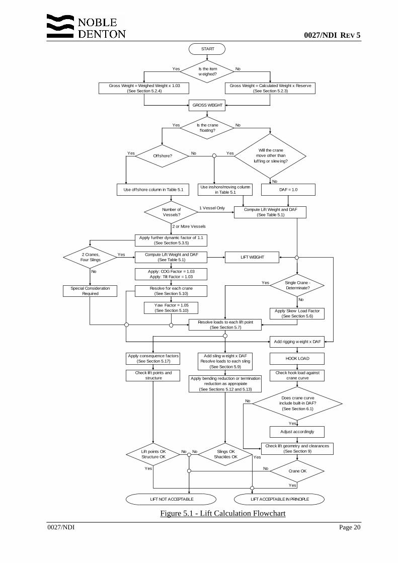
5.18 LIFTING CALCULATIONS FLOW CHART 5.18.1 The various factors and their application are illustrated in Figure 5.1.
5.18.2 This flowchart is for guidance only, and cannot cover every case. In case of any conflict between the flowchart and the text, the text shall govern.
0027/NDI REV 5
0027/NDI Page 20
Figure 5.1 - Lift Calculation Flowchart
START
Is the item w eighed?
Offshore?Will the crane
move other than luffing or slew ing?
Use offshore column in Table 5.1 Use inshore/moving column in Table 5.1 DAF = 1.0
Compute Lift Weight and DAF(See Table 5.1)
Number of Vessels?
Apply further dynamic factor of 1.1(See Section 5.3.5)
Gross Weight = Weighed Weight x 1.03(See Section 5.2.4)
Gross Weight = Calculated Weight x Reserve(See Section 5.2.3)
GROSS WEIGHT
Is the crane floating?
Single Crane - Determinate?
Apply Skew Load Factor(See Section 5.6)
Resolve loads to each lift point(See Section 5.7)
Apply: COG Factor = 1.03Apply: Tilt Factor = 1.03
Resolve for each crane(See Section 5.10)
Yaw Factor = 1.05(See Section 5.10)
HOOK LOADAdd sling w eight x DAFResolve loads to each sling
(See Section 5.9)
Apply consequence factors(See Section 5.17)
Check lift points and structure
Lift points OKStructure OK
Slings OKShackles OK
Crane OK
Check hook load against crane curve
Adjust accordingly
Does crane curve include built-in DAF?
(See Section 6.1)
Check lift geometry and clearances(See Section 9)
Apply bending reduction or termination reduction as appropiate
(See Sections 5.12 and 5.13)
LIFT ACCEPTABLE IN PRINCIPLE
Add rigging w eight x DAF
Compute Lift Weight and DAF(See Table 5.1) LIFT WEIGHT2 Cranes,
Four Slings
Special Consideration Required
Yes
Yes
Yes
Yes
Yes
Yes
Yes
Yes
Yes
No
No
No
No
No
No
2 or More Vessels
1 Vessel Only
LIFT NOT ACCEPTABLE
No
NoNoYes
No
0027/NDI REV 5
0027/NDI Page 21
6 THE CRANE AND CRANE VESSEL
6.1 HOOK LOAD 6.1.1 The hook load shall be shown not to exceed the allowable crane capacity as taken
from the load-radius curves.
6.1.2 The allowable curves as presented may sometimes include dynamic effects. If a suitable statement is received to this effect, the hook load may, for comparison with the load-radius curves, be derived from the gross weight, rather than the lift weight.
6.1.3 Some crane curves specify different allowable load curves for different seastates. These may similarly be taken to include dynamic effects. A seastate representing the probable limits for the operation should be chosen, and the gross weight used.
6.1.4 If the DAF included in the crane curves differs from the operation-specific value derived from Section 5.3.2, then the allowable load should be adjusted accordingly.
6.2 DOCUMENTATION 6.2.1 Where Approval is required, the documentation as stated in Section 15 shall be
submitted.
0027/NDI REV 5
0027/NDI Page 22
7 STRUCTURAL CALCULATIONS
7.1 LOAD CASES AND STRUCTURAL MODELLING 7.1.1 Structural calculations, based on the load factors discussed above, shall include
adequate loadcases to justify the structure. For example, for an indeterminate, 4-point lift the following loadcases should normally be considered;
a. Base case, using lift weight, resolved to the lift points, but with no skew load factor.
b. Lift weight, with skew load factor applied to one diagonal.
c. Lift weight, with skew load factor applied to the other diagonal.
7.1.2 In all cases the correct sling angle and point of action, and any offset or torsional loading imposed by the slings shall be considered.
7.2 STRUCTURE 7.2.1 The overall structure shall be analysed for the loadings shown in Section 7.1.
7.2.2 The primary supporting members shall be analysed using the most severe loading resulting from Section 7.1, with a consequence factor of 1.15 applied (see Section 5.17).
7.3 LIFT POINTS 7.3.1 An analysis of the lift points and attachments to the structure shall be performed,
using most severe load resulting from Section 7.1, and a consequence factor of 1.35 (see Section 5.17). The 5% side load (Section 5.8) should also be applied, as should any torsional load resulting from the 45:55 2-part sling loading (Section 5.11), if applicable.
7.3.2 Where the lift point forms a structural node, then the calculations shall also include the loads imposed by the members framing into it.
7.4 SPREADER BARS OR FRAMES 7.4.1 Spreader bars or frames, if used, should be similarly treated, with loadcases as above.
A consequence factor of 1.35 shall be applied to spreader bars and frames, in accordance with Section 5.17.
7.5 ALLOWABLE STRESSES 7.5.1 Stress levels shall be within those permitted by the latest edition of a recognised and
applicable offshore structures code. The loading shall be treated as a normal serviceability level functional load with associated load/resistance or safety factors (in a Working Stress code, the one third increase for environmental loadings shall not be allowed; similarly for an LRFD/partial factor code the load factor would be greater than that used for ultimate conditons.
0027/NDI REV 5
0027/NDI Page 23
7.5.2 Alternatively limit state analysis may be applied according to a recognised code, provided that;
a. The total load factor shall not be less than the product of all the factors required by Section 5, multiplied by a further factor of 1.30.
b. The material reduction factor shall be not less than;
• Elastic design of steel structures; 1.15 • Plastic design of steel structures; 1.30
0027/NDI REV 5
0027/NDI Page 24
8 LIFT POINT DESIGN
8.1 INTRODUCTION 8.1.1 In addition to the structural requirements shown in Sections 5 and 7, the following
should be taken into account in the lift point design;
8.2 SLING OVALISATION 8.2.1 Adequate clearance is required between cheek plates, or inside trunnion keeper
plates, to allow for ovalisation under load. In general, the width available for the sling shall be not less than (1.25D + 25mm), where D is nominal sling diameter. However, the practical aspects of the rigging and de-rigging operations may demand a greater clearance than this.
8.3 PLATE ROLLING AND LOADING DIRECTION 8.3.1 In general, for fabricated lift points, the direction of loading should be in line with
the plate rolling direction. Lift point drawings should show the rolling direction.
8.3.2 Through thickness loading of lift points and their attachments to the structure should be avoided if possible. If such loading cannot be avoided, the material used shall be documented to be free of laminations, with a recognised through-thickness designation.
8.4 PIN HOLES 8.4.1 Pin-holes should be bored/reamed, and should be designed to suit the shackle
proposed. Adequate spacer plates should be provided to centralise shackles.
8.5 CAST PADEARS 8.5.1 Cast padears shall be designed taking into account the following aspects;
• The geometrical considerations as indicated in Section 8.1 • The stress analysis process • The manufacturing process and quality control.
8.6 NON-DESTRUCTIVE TESTING 8.6.1 The extent of non-destructive testing shall be submitted for review.
8.6.2 Where repeated use is to be made of a lift point, a procedure should be presented for re-inspection after each lift.
0027/NDI REV 5
0027/NDI Page 25
9 CLEARANCES
9.1 INTRODUCTION 9.1.1 The required clearances will depend on the nature of the lift, the proposed limiting
weather conditions, the arrangement of bumpers and guides and the size and motion characteristics of the crane vessel and the transport barge.
9.1.2 Subject to the above, for offshore lifts, the following clearances should normally be maintained at each stage of the operation. Smaller clearances may be acceptable for inshore or onshore lifts.
9.2 CLEARANCES AROUND LIFTED OBJECT 9.2.1 3 metres between any part of the lifted object (including spreaders and lift points)
and crane boom.
9.2.2 3 metres vertical clearance between the underside of the lifted object and any other previously installed structure, except in the immediate vicinity of the proposed landing area.
9.2.3 3 metres between the lifted object and other structures on the same transport barge.
9.2.4 3 metres horizontal clearance between the lifted object and any other previously installed structure, unless purpose-built guides or bumpers are fitted.
9.2.5 3 metres remaining travel between travelling block and fixed block at maximum load elevation.
9.3 CLEARANCES AROUND CRANE VESSEL 9.3.1 Where the crane vessel is moored adjacent to an existing platform, 3m between any
part of the crane vessel and the platform and 10 m between any anchor line and the platform.
9.3.2 Where the crane vessel is dynamically positioned, 5m nominal between any part of the crane vessel and the platform.
9.3.3 3m between crane vessel and seabed, after taking account of tidal conditions, vessel motions, increased draft and changed heel or trim during the lift.
9.4 CLEARANCES AROUND MOORING LINES AND ANCHORS 9.4.1 The clearances stated below are given as guidelines to good practice. The specific
requirements and clearances should be defined for each project and operation, taking into account particular circumstances such as;
• water depth • proximity of subsea assets • survey accuracy • the control ability of the anchor handling vessel • seabed conditions • estimated anchor drag during embedment • the probable weather conditions during anchor installation.
9.4.2 Operators and contractors may have their own requirements which may differ from those stated below, and should govern if more conservative.
0027/NDI REV 5
0027/NDI Page 26
9.4.3 Clearances should take into account the possible working and stand-off positions of the crane vessel.
9.4.4 Moorings should never be laid in such a way that they could be in contact with any subsea asset. This may be relaxed when the subsea asset is a trenched pipeline, provided it can be demonstrated that the mooring will not cause frictional damage or abrasion.
9.4.5 Moorings shall never be run over the top of a subsea completion or wellhead.
9.4.6 Whenever an anchor is run out over a pipeline, flowline or umbilical, the anchor shall be securely stowed on the deck of the anchor handling vessel. In circumstances where either gravity anchors or closed stern tugs are used, and anchors cannot be stowed on deck, the anchors shall be double secured through the additional use of a safety strap or similar.
9.4.7 The vertical clearance between any anchor line and any subsea asset should be not less that 20 metres in water depths exceeding 40 metres, and 50% of water depth in depths of less than 40 metres.
9.4.8 Clearance between any mooring line and any structure other than a subsea asset should be not less than 10 metres.
9.4.9 When an anchor is placed on the same side of a subsea asset as the crane vessel, it should not be placed closer to the subsea asset than 100 metres.
9.4.10 When the subsea asset lies between the anchor and the crane vessel, the final anchor position should be not less than 200 metres from the subsea asset.
9.4.11 During lifting operations, crossed mooring situations should be avoided wherever practical. Where crossed moorings cannot be avoided, the separation between active catenaries should be not less than 30 metres in water depths exceeding 100 metres, and 30% of water depth in water depths less than 100 metres.
9.4.12 If any of the clearances specified in Sections 9.4.7 through 9.4.11 are impractical because of the mooring configuration or seabed layout, a risk assessment shall be carried out and special precautions taken as necessary.
0027/NDI REV 5
0027/NDI Page 27
10 BUMPERS AND GUIDES
10.1 INTRODUCTION 10.1.1 For module installation the arrangement and design philosophy for bumpers and
guides shall be submitted, where applicable. In general, bumpers and guides should be designed in accordance with the following;
10.2 MODULE MOVEMENT 10.2.1 The maximum module movement during installation should be defined. In general
the module motions should be limited to;
• Vertical movement; + 0.75 m • Horizontal movement; + 1.50 m • Longitudinal tilt; 2 degrees • Transverse tilt; 2 degrees • Plan rotation; 3 degrees.
10.2.2 The plan rotation limit is only applicable when the module is close to its final position.
10.3 POSITION OF BUMPERS AND GUIDES 10.3.1 The position of bumpers and guides shall be determined taking into account
acceptable support points on the module.
10.4 BUMPER AND GUIDE FORCES 10.4.1 For offshore lifts, bumpers and guides should be designed to the following forces
(where Wg = gross weight);
a) Vertical sliding bumpers
Horizontal for in plane of bumper; 0.10 x Wg
Horizontal (friction) force, out of plane of bumper; 0.05 x Wg
Vertical (friction) force; 0.01 x Wg
Forces in all 3 directions will be combined to establish the worst design case.
b) Pin/bucket guides
Horizontal force on cone/end of pin; 0.05 x Wg
Vertical force on cone/end of pin; 0.10 x Wg
Horizontal force in any direction will be combined with the vertical force to establish the worst design.
c) Horizontal “cow-horn” type bumpers with vertical guide
Horizontal force in any direction; 0.10 x Wg
Vertical (friction) force; 0.01 x Wg
Horizontal force in any direction will be combined with vertical force to establish the worst design case.
0027/NDI REV 5
0027/NDI Page 28
d) Vertical “cow-horn” type guide with horizontal bumper
Horizontal force in any direction; 0.05 x Wg
Vertical force on inclined guide-face; 0.10 x Wg
Horizontal force in any direction will be combined with vertical force to establish the worst design case.
10.4.2 For inshore lifts under controlled conditions, bumpers and guides may be designed to 70% of the forces shown in Section 10.4.1.
10.5 DESIGN CONSIDERATIONS 10.5.1 The connection into the module, and the members framing the bumper or guide
location, should be at least as strong as the bumper or guide.
10.5.2 The stiffness of bumper and guide members should be as low as possible, in order that they may deflect appreciably without yielding.
10.5.3 Design of bumpers and guides should cater for easy sliding motion of the guide in contact with bumper. Sloping members should be at an acute angle to the vertical. Ledges and sharp corners should be avoided on areas of possible contact, and weld beads should be ground flush.
0027/NDI REV 5
0027/NDI Page 29
11 UNDERWATER LIFTING 11.1 If any part of the lift operation includes lifting or lowering through water,
information shall be submitted, which either;
• Shows how the total in-water lifting loads are derived, taking into account the weight, buoyancy, entrained mass, boom-tip velocities and accelerations, inertia and drag forces, or
• Demonstrates that the in-water case is not critical.
12 HEAVE COMPENSATED LIFTS 12.1 Lifts which are to be performed under heave compensation should be reviewed with
great care to ensure that the limitations of the equipment and procedures have been correctly identified. In determining limiting seastates, any single point failure of the heave compensation system or its operation should be justified as an accidental load case.
13 LIFTS USING DYNAMIC POSITIONING (DP) 13.1 Lifts using Dynamic Positioning (DP) shall be carefully considered on a case-by-case
basis, in accordance with the requirements of industry best practice.
0027/NDI REV 5
0027/NDI Page 30
14 PRACTICAL CONSIDERATIONS 14.1 Adequate and safe access and working platforms should be provided for connection
of slings, particularly where connection or disconnection is required offshore or underwater.
14.2 Seafastening on the transport barge should be designed;
• To minimise offshore cutting • To provide restraint after cutting • To allow lift off without fouling.
14.3 All cut lines should be clearly marked. Where a 2-stage lift is planned - eg barge to SSCV, then SSCV to final position, involving 2 sets of cut lines, these should preferably be in different colours.
14.4 Adequate equipment must be available on the transport barge, including as appropriate;
• Burning sets • Tuggers and lifting gear • Means of securing loose seafastening material • Lighting for night operations • Safety equipment for personnel.
14.5 All loose equipment, machinery, pipework and scaffolding shall be secured against movement during the lift, and the weights and positions allowed for in the gross weight.
14.6 Prior to the start of the lift, a forecast of suitable weather shall be received, of a duration adequate to complete the operation, with contingencies, and taking into account any subsequent critical marine operations.
14.7 The sling laydown arrangement shall show that;
a. The slinging arrangement is in accordance with acceptable practice.
b. The slings are matched as accurately as possible, unless the rigging arrangement is deliberately non-symmetrical to take account of centre of gravity offset, in which case matched pairs of slings should normally be used. Where minor mismatch in sling length exists, the slings should be arranged to minimise skew loads.
c. The slings are adequately secured against barge motions, prior to the start of the lift.
d. The slings will not foul obstructions such as walkways and handrails when lifted, and any unavoidable obstructions are properly protected.
e. The slings will not kink when lifted.
f. After the lift the slings (and spreaders if used) can be safely laid down again, without damage.
14.8 Slings with hand spliced terminations must be prevented from rotation.
14.9 No bending is allowed at or close to a termination.
14.10 It is permissible to shackle slings together end-to-end to increase the length. However, slings of opposite lay should never be connected together.
0027/NDI REV 5
0027/NDI Page 31
14.11 It is permissible to increase the length of a sling by inserting extra shackles. Any shackle to shackle connections should be pin-to-bow or bow-to-bow, not pin-to-pin.
14.12 Crane vessel motions should be monitored in the period prior to the lift, to confirm that the dynamic behaviour is acceptable, taking into account the weight and size of the lifted object, the clearances for lifting off the transport barge, the hoisting speed, the clearances for installation and the installation tolerances.
14.13 Transport barge motions should be similarly monitored prior to the start of the lift. The change in attitude of the transport barge when the weight is removed should be taken into account.
0027/NDI REV 5
0027/NDI Page 32
15 INFORMATION REQUIRED FOR APPROVAL
15.1 GENERAL INFORMATION REQUIRED 15.1.1 Where approval is required, a package shall be submitted to Noble Denton for
review, consisting of;
a. Justification of weight and centre of gravity, by Weight Control Report or weighing report.
b. Structural analysis report for structure to be lifted, including lift points and spreaders, as set out in Section 7.
c. Rigging arrangement package, showing sling geometry, computed sling loads, required breaking loads, tabulation of slings and shackles proposed, certificates for slings and shackles.
d. Crane details, including load-radius curve with lift superimposed, and details of vertical and horizontal clearances, and mooring arrangements.
e. The management structure and marine procedures.
15.2 THE STRUCTURE TO BE LIFTED 15.2.1 Calculations shall be presented for the structure to be lifted, demonstrating its
capacity to withstand, without overstress, the loads imposed by the lift operation, with the load and safety factors stated in Section 5, and the loadcases discussed in Section 7.
15.2.2 The calculation package shall present, as a minimum;
a. Plans, elevations and sections showing main structural members
b. The structural model. This should account for the proposed lifting geometry, including any offset of the lift points
c. The weight and centre of gravity
d. The steel grades and properties
e. The loadcases imposed
f. The Codes used
g. A tabulation of member Unity Checks, or a statement that Unity Checks are less than 0.8
h. Justification, or proposal for redesign, for any members with a Unity Check in excess of 1.0.
15.2.3 An analysis or equivalent justification shall be presented for all lift points, including padeyes, padears and trunnions, to demonstrate that each lift point, and its attachment into the structure, is adequate for the loads and factors set out in Sections 5 and 7.
15.2.4 A similar analysis shall be presented for spreader bars, beams and frames.
15.3 INDEPENDENT ANALYSIS Alternatively, Noble Denton will, if instructed, perform an independent analysis of the structure to be lifted, including the lift points, on receipt of the necessary information.
0027/NDI REV 5
0027/NDI Page 33
15.4 CODES AND SPECIFICATIONS 15.4.1 For analysis of the structure to be lifted and the lift points, an accepted structural
code shall be used as described in Section 7.5.
15.4.2 Adequate specifications for material properties, construction, welding, casting, inspection and testing shall be used.
15.5 EVIDENCE OF SATISFACTORY CONSTRUCTION Confirmation shall be presented, from a Certifying Authority, Classification Society or similar, that the structure including the lift points and their attachments has been constructed in accordance with the drawings and specifications.
15.6 RIGGING ARRANGEMENTS 15.6.1 A proposal shall be presented showing:
a. The proposed rigging geometry showing dimensions of the structure, centre of gravity position, lift points, crane hook, sling lengths and angles, including shackle dimensions and "lost" length around hook and trunnions.
b. A computation of the sling and shackle loads and required breaking loads, taking into account the factors set out in Section 5.
c. A list of actual slings and shackles proposed, tabulating;
• Position on structure
• Sling/shackle identification number
• Sling length and diameter
• Minimum breaking load for slings, SWL and MBL for shackles
• Construction
• Direction of lay
d. Copies of inspection/test Certificates for all rigging components.
15.6.2 Slings and grommets should be manufactured and inspected in accordance with the International Marine Contractors Association Guidance on Cable laid slings and grommets (Reference 3) or similar acceptable standard. A thorough examination shall be carried out as required by that document.
15.6.3 Shackles manufactured by an industry-recognised manufacturer, shall be covered by a test certificate not exceeding 5 years old, and if not new, a report of an inspection by a competent person since the last lift.
0027/NDI REV 5
0027/NDI Page 34
15.7 THE CRANE VESSEL 15.7.1 Information shall be submitted on the crane vessel and the crane. This shall include,
as appropriate;
• Vessel general arrangement drawings and specification
• Details of registry and class
• Mooring system and anchors
• Operating and survival drafts
• Crane specification and operating curves
• Details of any ballasting operations required during the lift.
15.7.2 The mooring arrangement for the operation and stand-off position shall be submitted. This should include the lengths and specifications of all mooring wires and anchors, and a mooring plan showing adequate horizontal clearances on all platforms, pipelines and any other seabed obstructions. An elevation of the catenary for each mooring line, for upper and lower tension limits, shall demonstrate adequate vertical clearance over pipelines.
15.8 PROCEDURES AND MANAGEMENT 15.8.1 Sufficient management and resources shall be provided to carry out the operation
efficiently and safely.
15.8.2 Quality, safety and environmental hazards shall be managed by a formal Quality Management system.
15.8.3 The management structure for the operation, including reporting and communication systems, and links to safety and emergency services shall be demonstrated.
15.8.4 The anticipated timing and duration of each operation shall be submitted.
15.8.5 The arrangements for control, manoeuvring and mooring of barges and/or other craft alongside the crane vessel shall be submitted.
15.8.6 A weather forecast from an approved source, predicting that conditions will be within the prescribed limits, shall be received prior to the start of the operation, and at 12 hourly intervals thereafter, until the operation is deemed complete, in accordance with Section 4.5.3.
0027/NDI REV 5
0027/NDI Page 35
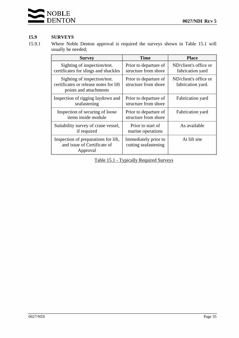
15.9 SURVEYS 15.9.1 Where Noble Denton approval is required the surveys shown in Table 15.1 will
usually be needed;
Survey Time Place Sighting of inspection/test.
certificates for slings and shacklesPrior to departure of structure from shore
ND/client's office or fabrication yard
Sighting of inspection/test. certificates or release notes for lift
points and attachments
Prior to departure of structure from shore
ND/client's office or fabrication yard.
Inspection of rigging laydown and seafastening
Prior to departure of structure from shore
Fabrication yard
Inspection of securing of loose items inside module
Prior to departure of structure from shore
Fabrication yard
Suitability survey of crane vessel, if required
Prior to start of marine operations
As available
Inspection of preparations for lift, and issue of Certificate of
Approval
Immediately prior to cutting seafastening
At lift site
Table 15.1 - Typically Required Surveys
0027/NDI REV 5
0027/NDI Page 36
REFERENCES
Reference 1 Noble Denton Report 0013/NDI - Guidelines for Loadouts.
Reference 2 ISO International Standard ISO 19901-5:2003 – Petroleum and natural gas industries – specific requirements for offshore structures – Part 5: Weight control during engineering and construction.
Reference 3 The International Marine Contractors Association - Guidance on The Use of Cable Laid Slings and Grommets - IMCA M 179 August 2005.


