0 7 8 - 0 4 0 3 - 0 1 A
®
NodeBuilder® FX/PL
Examples Guide

ii
Echelon, LON, LonWorks, Neuron, 3120, 3150, Digital Home, i.LON, LNS, LonMaker, LonMark, LonPoint, LonTalk, NodeBuilder, and the Echelon logo are trademarks of Echelon Corporation registered in the United States and other countries. LonScanner, LonSupport, OpenLDV, and LNS Powered by Echelon are trademarks of Echelon Corporation.
Other brand and product names are trademarks or registered trademarks of their respective holders.
Neuron Chips and other OEM Products were not designed for use in equipment or systems which involve danger to human health or safety or a risk of property damage and Echelon assumes no responsibility or liability for use of the Neuron Chips or LonPoint Modules in such applications.
Parts manufactured by vendors other than Echelon and referenced in this document have been described for illustrative purposes only, and may not have been tested by Echelon. It is the responsibility of the customer to determine the suitability of these parts for each application.
ECHELON MAKES NO REPRESENTATION, WARRANTY, OR CONDITION OF ANY KIND, EXPRESS, IMPLIED, STATUTORY, OR OTHERWISE OR IN ANY COMMUNICATION WITH YOU, INCLUDING, BUT NOT LIMITED TO, ANY IMPLIED WARRANTIES OF MERCHANTABILITY, SATISFACTORY QUALITY, FITNESS FOR ANY PARTICULAR PURPOSE, NONINFRINGEMENT, AND THEIR EQUIVALENTS.
No part of this publication may be reproduced, stored in a retrieval system, or transmitted, in any form or by any means, electronic, mechanical, photocopying, recording, or otherwise, without the prior written permission of Echelon Corporation.
Printed in the United States of America. Copyright ©1997–2009 by Echelon Corporation. Echelon Corporation www.echelon.com
NodeBuilder FX/PL Examples Guide iii
Table of Contents Preface .................................................................................................... iv
Purpose ........................................................................................................... v Audience.......................................................................................................... v System Requirements ..................................................................................... v Content ........................................................................................................... vi Related Manuals............................................................................................. vi For More Information and Technical Support.................................................vii
1 Using the NodeBuilder FX/PL Example........................................... 1 Introduction to the NodeBuilder FX/PL Example............................................. 2
Using the Pre-Built Example Device Application ...................................... 4 Restoring the LonMaker Network Backup.......................................... 4 Downloading the Example Application ............................................... 8 Testing the I/O Devices on the Gizmo 4 I/O Board .......................... 10
Testing Switch and Lamp Devices............................................. 10 Testing Alarm Devices ............................................................... 11
Creating the Example Device Application............................................... 14 Step 1: Creating the NodeBuilder Project ....................................... 14 Step 2: Configuring the Node Object................................................ 15 Step 3: Adding Digital I/O ................................................................. 16 Step 4: Implementing Analog Input and Output ............................... 18 Step 5: Implementing a Simple Type Translator .............................. 22 Step 6: Enhancing the Type Translator............................................ 23 Step 7: Implementing the Temperature Sensor ............................... 25 Step 8: Implementing the Real Time Keeper ................................... 27 Step 9: Implementing the Wheel Input ............................................. 30
Continuing with the NodeBuilder Example .................................................... 34
iv Preface
Preface
The NodeBuilder® FX/PL Development Tool includes a Neuron C example application that you can load into your LTM-10A Platform. You can use this
example to test the I/O devices on the Gizmo 4 I/O Board, and create a simple managed LONWORKS® network. You can follow the instructions in this document to
create the example device application from scratch.
NodeBuilder FX/PL Examples Guide v
Purpose This document describes how to load and use the Neuron C example application included with the NodeBuilder FX/PL Development Tool.
Audience This guide is intended for device and system designers with an understanding of control networks.
System Requirements Requirements for computers running the NodeBuilder PL examples are listed below:
• Microsoft® Windows Vista or Microsoft Windows XP. Echelon recommends that you install the latest service pack available from Microsoft for your version of Windows.
• Intel® Pentium® III 600MHz processor or faster, and meeting the minimum Windows requirements for the selected version of Windows.
• 300 to 550 megabytes (MB) free hard-disk space, plus the minimum Windows requirements for the selected version of Windows.
o The NodeBuilder tool requires 100 MB of free space.
o The LonMaker® Integration Tool, which is included with the NodeBuilder software and is required to install the NodeBuilder tool, requires 172 MB of free space.
o The LonScanner™ Protocol Analyzer, which is included with the NodeBuilder software, requires 26 MB of free space.
o Microsoft .NET Framework 3.5 SP1, which is required to run the NodeBuilder tool, requires 30 MB of free space.
o If you install Acrobat® Reader 9.1 from the NodeBuilder FX Development Tool CD, you need an additional 204 MB of free space.
• 512 MB RAM minimum.
Note: Vista testing for the NodeBuilder tool has been performed on computers that have a minimum of 2 GB of RAM. For complete Vista requirements, refer to www.microsoft.com/windows/windows-vista/get/system-requirements.aspx. You can use Microsoft’s Vista Upgrade Advisor to determine upgrade requirements for a particular computer. To download this tool, go to the Microsoft Web site at www.microsoft.com/windows/windows-vista/get/upgrade-advisor.aspx.
• CD-ROM drive.
• 1024x768 or higher-resolution display with at least 256 colors.
• Mouse or compatible pointing device.
• LNS® network interface or IP-852 router. If an LNS network interface is used, it may be a local or remote interface.
o Compatible local network interfaces include the U20 USB network interface (included with the NodeBuilder FX/PL Development Tool.
o Compatible remote network interfaces include the i.LON® SmartServer, i.LON 100 e3 Internet Server, i.LON 600 LONWORKS-IP Server, or i.LON 10 Ethernet Adapter.
o Compatible IP-852 routers include the i.LON SmartServer with IP-852 routing, i.LON 100 e3 Internet Server with IP-852 routing, or an i.LON 600 LONWORKS-IP Server. If you are using
vi Preface
an IP-852 router, your computer must have an IP network interface such as an Ethernet card or modem with PPP software. In addition, the i.LON software must be installed on your computer, and the IP-852 channel must be configured using the LONWORKS-IP Configuration Server application software.
The LonMaker tool, which is included with the NodeBuilder software, automatically installs drivers for all local and remote network interfaces, except the SLTA-10 Serial LonTalk Adapter. The LonMaker CD includes an option for installing the driver for the SLTA-10 Serial LonTalk Adapter.
Note: You must run the NodeBuilder software on the same computer with the LNS Server which is installed by the LonMaker installer. You cannot run the NodeBuilder tool as a remote client to an LNS Server running on another computer.
Content This guide includes the following content:
• Using the NodeBuilder FX/PL Example. Introduces the Neuron C example application that you can run on an LTM-10A Platform and test with the Gizmo 4 I/O Board. Describes how to load the pre-built example application on an LTM-10A Platform using the LonMaker Integration Tool, which is included with the NodeBuilder FX Development tool, and describes how to use the I/O devices on the Gizmo 4 I/O Board to test the example application. Includes a detailed nine-step exercise that you can follow to create the example device application from scratch.
Related Manuals The documentation related to the NodeBuilder tool is provided as Adobe PDF files and online help files. The PDF files for the NodeBuilder tool are installed in the Echelon NodeBuilder program folder when you install the NodeBuilder tool. You can download the latest NodeBuilder and documentation, including the latest version of this guide, from Echelon’s website at www.echelon.com/docs.
Gizmo 4 User's Guide Describes how to use the I/O devices on the Gizmo 4 I/O Board, and how to use the Gizmo 4 I/O Board to build your own I/O hardware.
The Gizmo 4 I/O Board is included with the NodeBuilder FX/PL Development Tool.
Introduction to the LONWORKS® Platform
Provides a high-level introduction to LONWORKS networks and the tools and components that are used for developing, installing, operating, and maintaining them.
LNS®Plug-in Programmer's Guide Describes how to write plug-ins using .NET programming languages such as C# and Visual Basic .NET
LonMaker® User’s Guide Describes how to use the LonMaker Integration Tool to design, commission, modify, and maintain LONWORKS networks.
LONMARK® SNVT and SCPT Guide Documents the standard network variable types (SNVTs), standard configuration property types (SCPTs), and standard enumeration types that you can declare in your applications.
LONWORKS® USB Network Interface User's Guide
Describes how to install and use the U20 USB Network Interfaces, which is included with NodeBuilder FX/PL Development Tool.

NodeBuilder FX/PL Examples Guide vii
LTM-10A User's Guide Describes how to use the LTM-10A Platform for testing your applications and I/O hardware prototypes. Also describes how you can design the LTM-10A flash Control Module into your products.
The LTM-10A Platform is included with the NodeBuilder FX/PL Development Tool.
Neuron® C Programmer’s Guide Describes how to write programs using the Neuron C Version 2.2 language.
Neuron® C Reference Guide Provides reference information for writing programs using the Neuron C language.
Neuron® Tools Error Guide Provides reference information for Neuron C errors.
NodeBuilder® FX User’s Guide Describes how to use the NodeBuilder tool to develop LONWORKS device applications and build and test prototype and production LONWORKS devices
NodeBuilder® Resource Editor User’s Guide
Describes how to use the NodeBuilder Resource Editor to create and edit resource file sets and resources such as functional profile templates, network variable types, and configuration property types.
For More Information and Technical Support The NodeBuilder ReadMe file provides descriptions of known problems, if any, and their workarounds. To view the NodeBuilder ReadMe, click Start, point to Programs, point to NodeBuilder, and then select NodeBuilder ReadMe First. You can also find additional information about the NodeBuilder tool at the NodeBuilder Web page at www.echelon.com/nodebuilder.
If you have technical questions that are not answered by this document, the NodeBuilder online help, or the NodeBuilder ReadMe file, you can contact technical support. To receive technical support from Echelon, you must purchase support services from Echelon or an Echelon support partner. See www.echelon.com/support for more information on Echelon support and training services.
You can also enroll in training classes at Echelon or an Echelon training center to learn more about developing devices. You can find additional information about device development training at www.echelon.com/training.
You can obtain technical support via phone, fax, or e-mail from your closest Echelon support center. The contact information is as follows:
Region Languages Supported Contact Information The Americas
English Japanese
Echelon Corporation Attn. Customer Support 550 Meridian Avenue San Jose, CA 95126 Phone (toll-free): 1-800-258-4LON (258-4566) Phone: +1-408-938-5200 Fax: +1-408-790-3801 [email protected]

viii Preface
Region Languages Supported Contact Information Europe
English German French Italian
Echelon Europe Ltd. Suite 12 Building 6 Croxley Green Business Park Hatters Lane Watford Hertfordshire WD18 8YH United Kingdom Phone: +44 (0)1923 430200 Fax: +44 (0)1923 430300 [email protected]
Japan
Japanese Echelon Japan Holland Hills Mori Tower, 18F 5-11-2 Toranomon, Minato-ku Tokyo 105-0001 Japan Phone: +81-3-5733-3320 Fax: +81-3-5733-3321 [email protected]
China
Chinese English
Echelon Greater China Rm. 1007-1008, IBM Tower Pacific Century Place 2A Gong Ti Bei Lu Chaoyang District Beijing 100027, China Phone: +86-10-6539-3750 Fax: +86-10-6539-3754 [email protected]
Other Regions
English Japanese
Phone: +1-408-938-5200 Fax: +1-408-328-3801 [email protected]
NodeBuilder FX/PL Examples Guide 1
1
Using the NodeBuilder FX/PL Example
This chapter introduces the Neuron C example application that you can run on an LTM-10A Platform and test with the Gizmo 4 I/O Board. It describes how to load
the pre-built example application on an LTM-10A Platform using the LonMaker Integration Tool, which is included with the NodeBuilder FX Development tool, and how to use the I/O devices on the Gizmo 4 I/O Board to test the example application.
It includes a detailed nine-step exercise that you can follow to create the example device application from scratch.
2 Using the NodeBuilder FX/PL Example
Introduction to the NodeBuilder FX/PL Example The NodeBuilder FX/PL Development Tool includes a Neuron C example application, NcExample, that you can load into your LTM-10A Platform. You can use this example application to test the I/O devices on the Gizmo 4 I/O Board, and create simple managed LONWORKS networks.
The example application is designed to run on a Gizmo 4 I/O Board attached to an LTM-10A Platform. If you do not have a Gizmo 4 I/O Board, you can still use the NodeBuilder tool to create and compile the application, but you cannot observe how the device application interacts with the I/O devices Gizmo 4 I/O Board.
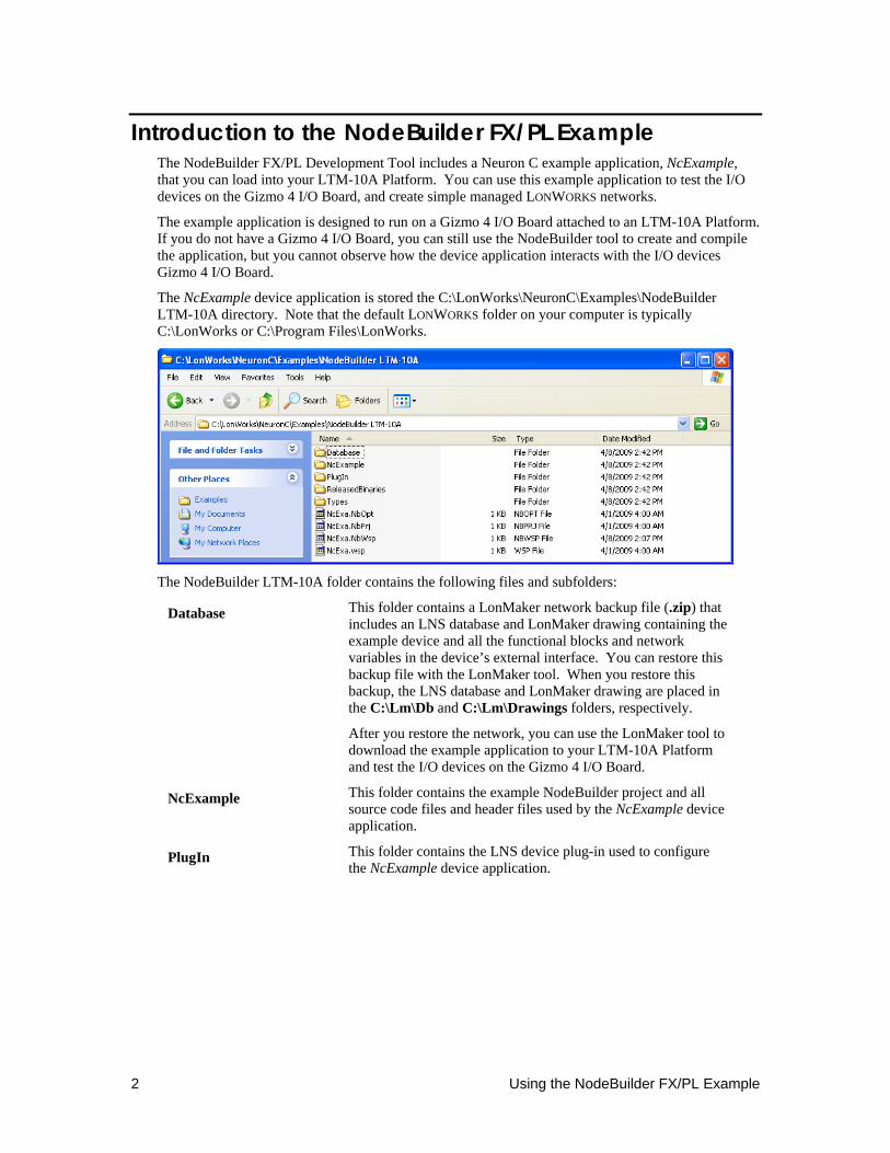
The NcExample device application is stored the C:\LonWorks\NeuronC\Examples\NodeBuilder LTM-10A directory. Note that the default LONWORKS folder on your computer is typically C:\LonWorks or C:\Program Files\LonWorks.
The NodeBuilder LTM-10A folder contains the following files and subfolders:
Database This folder contains a LonMaker network backup file (.zip) that includes an LNS database and LonMaker drawing containing the example device and all the functional blocks and network variables in the device’s external interface. You can restore this backup file with the LonMaker tool. When you restore this backup, the LNS database and LonMaker drawing are placed in the C:\Lm\Db and C:\Lm\Drawings folders, respectively.
After you restore the network, you can use the LonMaker tool to download the example application to your LTM-10A Platform and test the I/O devices on the Gizmo 4 I/O Board.
NcExample This folder contains the example NodeBuilder project and all source code files and header files used by the NcExample device application.
PlugIn This folder contains the LNS device plug-in used to configure the NcExample device application.
NodeBuilder FX/PL Examples Guide 3
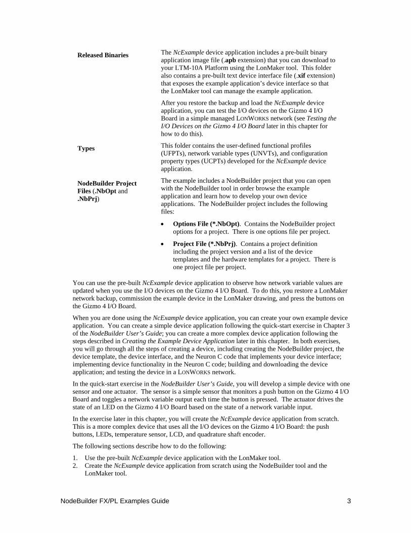
Released Binaries The NcExample device application includes a pre-built binary application image file (.apb extension) that you can download to your LTM-10A Platform using the LonMaker tool. This folder also contains a pre-built text device interface file (.xif extension) that exposes the example application’s device interface so that the LonMaker tool can manage the example application.
After you restore the backup and load the NcExample device application, you can test the I/O devices on the Gizmo 4 I/O Board in a simple managed LONWORKS network (see Testing the I/O Devices on the Gizmo 4 I/O Board later in this chapter for how to do this).
Types This folder contains the user-defined functional profiles (UFPTs), network variable types (UNVTs), and configuration property types (UCPTs) developed for the NcExample device application.
NodeBuilder Project Files (.NbOpt and .NbPrj)
The example includes a NodeBuilder project that you can open with the NodeBuilder tool in order browse the example application and learn how to develop your own device applications. The NodeBuilder project includes the following files:
• Options File (*.NbOpt). Contains the NodeBuilder project options for a project. There is one options file per project.
• Project File (*.NbPrj). Contains a project definition including the project version and a list of the device templates and the hardware templates for a project. There is one project file per project.
You can use the pre-built NcExample device application to observe how network variable values are updated when you use the I/O devices on the Gizmo 4 I/O Board. To do this, you restore a LonMaker network backup, commission the example device in the LonMaker drawing, and press the buttons on the Gizmo 4 I/O Board.
When you are done using the NcExample device application, you can create your own example device application. You can create a simple device application following the quick-start exercise in Chapter 3 of the NodeBuilder User’s Guide; you can create a more complex device application following the steps described in Creating the Example Device Application later in this chapter. In both exercises, you will go through all the steps of creating a device, including creating the NodeBuilder project, the device template, the device interface, and the Neuron C code that implements your device interface; implementing device functionality in the Neuron C code; building and downloading the device application; and testing the device in a LONWORKS network.
In the quick-start exercise in the NodeBuilder User’s Guide, you will develop a simple device with one sensor and one actuator. The sensor is a simple sensor that monitors a push button on the Gizmo 4 I/O Board and toggles a network variable output each time the button is pressed. The actuator drives the state of an LED on the Gizmo 4 I/O Board based on the state of a network variable input.
In the exercise later in this chapter, you will create the NcExample device application from scratch. This is a more complex device that uses all the I/O devices on the Gizmo 4 I/O Board: the push buttons, LEDs, temperature sensor, LCD, and quadrature shaft encoder.
The following sections describe how to do the following:
1. Use the pre-built NcExample device application with the LonMaker tool. 2. Create the NcExample device application from scratch using the NodeBuilder tool and the
LonMaker tool.
4 Using the NodeBuilder FX/PL Example
Using the Pre-Built Example Device Application You can use the LonMaker tool to download the NcExample device application to the LTM-10A Platform and install it in a LONWORKS network. To do this, you restore the NcExa.zip file in the LonWorks\NeuronC\Examples\NodeBuilder LTM-10A\Database folder, load the pre-built binary application image file (.apb extension) for the NcExample application to the device, and then commission the example device. After you install the example device, you can use the I/O devices on the Gizmo 4 I/O Board and observe how network variable values are updated.
Restoring the LonMaker Network Backup
To restore the LonMaker network backup, follow these steps:
1. Connect your LTM-10A and Gizmo 4 I/O Board following Chapter 2 of the NodeBuilder User’s Guide or the Quick-Start Guide included with your NodeBuilder FX/PL Development Tool.
2. Verify that you have installed and activated the LonMaker tool following Chapter 2 of the LonMaker User’s Guide.
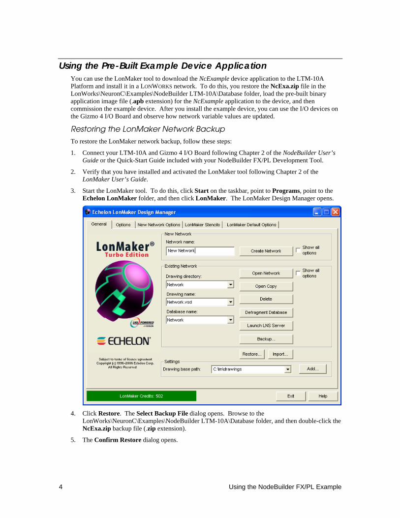
3. Start the LonMaker tool. To do this, click Start on the taskbar, point to Programs, point to the Echelon LonMaker folder, and then click LonMaker. The LonMaker Design Manager opens.
4. Click Restore. The Select Backup File dialog opens. Browse to the
LonWorks\NeuronC\Examples\NodeBuilder LTM-10A\Database folder, and then double-click the NcExa.zip backup file (.zip extension).
5. The Confirm Restore dialog opens.
NodeBuilder FX/PL Examples Guide 5
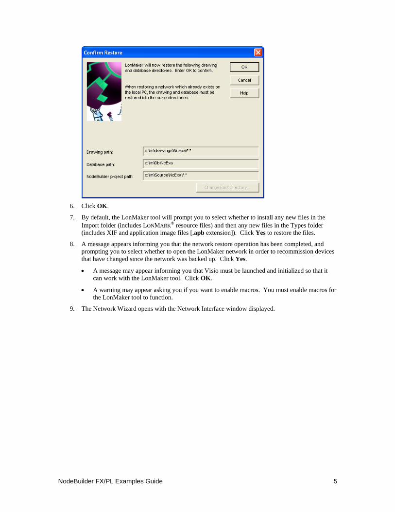
6. Click OK.
7. By default, the LonMaker tool will prompt you to select whether to install any new files in the Import folder (includes LONMARK® resource files) and then any new files in the Types folder (includes XIF and application image files [.apb extension]). Click Yes to restore the files.
8. A message appears informing you that the network restore operation has been completed, and prompting you to select whether to open the LonMaker network in order to recommission devices that have changed since the network was backed up. Click Yes.
• A message may appear informing you that Visio must be launched and initialized so that it can work with the LonMaker tool. Click OK.
• A warning may appear asking you if you want to enable macros. You must enable macros for the LonMaker tool to function.
9. The Network Wizard opens with the Network Interface window displayed.

6 Using the NodeBuilder FX/PL Example
10. Select the Network Attached check box. In the Network Interface Name property select the
network interface to be used for communication between the LonMaker tool and the LTM-10A Platform over the LONWORKS channel. Click Next.
You can use the U20 USB Network Interface included with the NodeBuilder FX/PL Development Tool, or you can use another network interface such as an i.LON SmartServer or an i.LON 100 e3 Internet Server. If you are using the U20 USB Network Interface included with the NodeBuilder FX/PL Development Tool and you have not installed any other network interfaces on your computer, select LON1.
For more information on installing and configuring the U20 USB Network Interface, and on using it to attach your computer to a network channel, see the LONWORKS USB Network Interface User’s Guide.
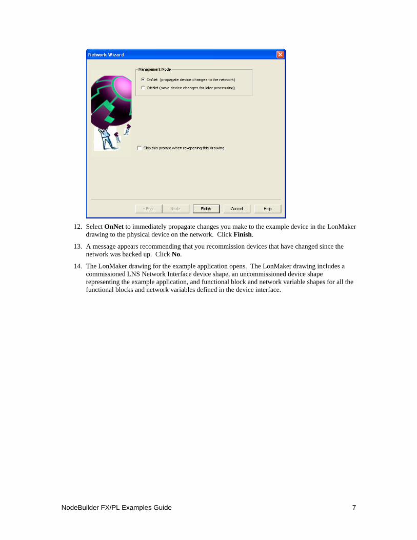
11. The Management Mode window opens.
NodeBuilder FX/PL Examples Guide 7
12. Select OnNet to immediately propagate changes you make to the example device in the LonMaker
drawing to the physical device on the network. Click Finish.
13. A message appears recommending that you recommission devices that have changed since the network was backed up. Click No.
14. The LonMaker drawing for the example application opens. The LonMaker drawing includes a commissioned LNS Network Interface device shape, an uncommissioned device shape representing the example application, and functional block and network variable shapes for all the functional blocks and network variables defined in the device interface.
8 Using the NodeBuilder FX/PL Example
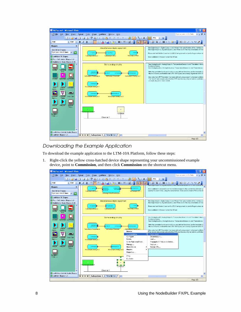
Downloading the Example Application
To download the example application to the LTM-10A Platform, follow these steps:
1. Right-click the yellow cross-hatched device shape representing your uncommissioned example device, point to Commission, and then click Commission on the shortcut menu.
NodeBuilder FX/PL Examples Guide 9
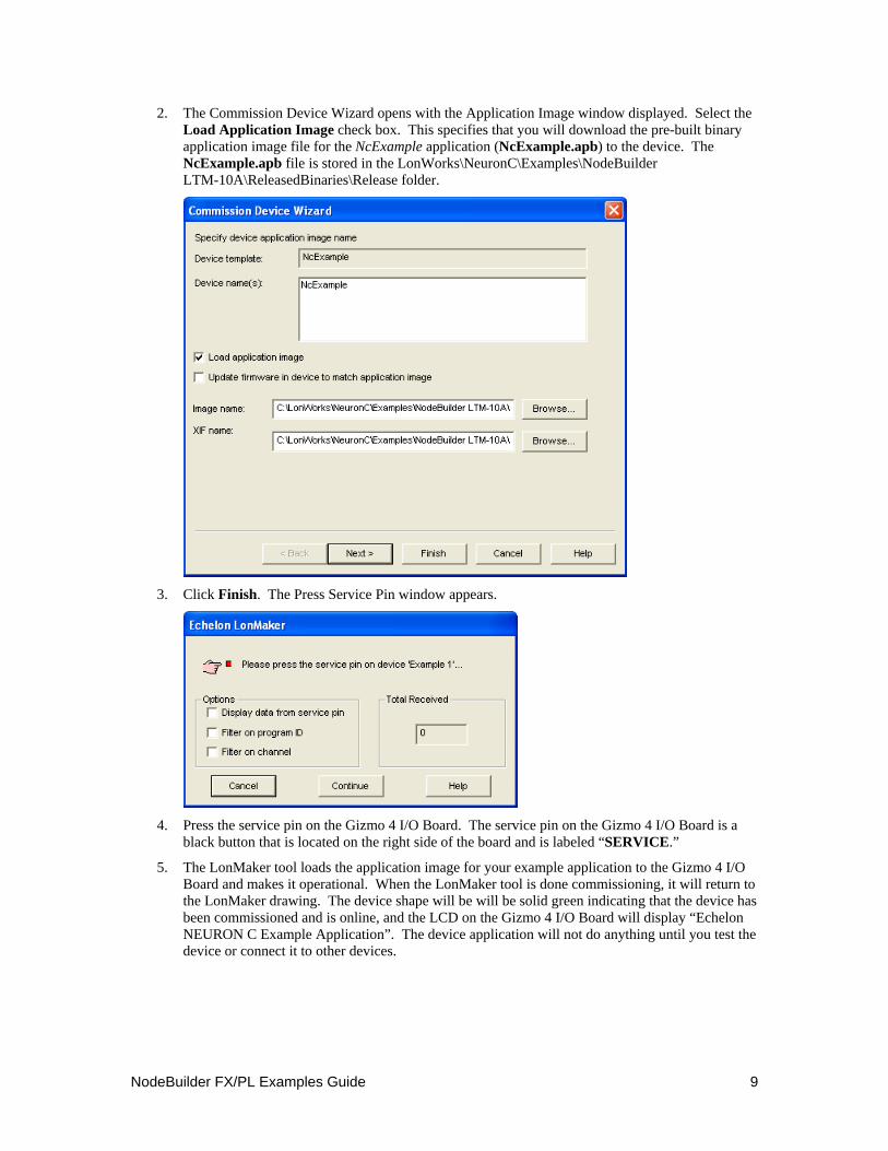
2. The Commission Device Wizard opens with the Application Image window displayed. Select the Load Application Image check box. This specifies that you will download the pre-built binary application image file for the NcExample application (NcExample.apb) to the device. The NcExample.apb file is stored in the LonWorks\NeuronC\Examples\NodeBuilder LTM-10A\ReleasedBinaries\Release folder.
3. Click Finish. The Press Service Pin window appears.
4. Press the service pin on the Gizmo 4 I/O Board. The service pin on the Gizmo 4 I/O Board is a
black button that is located on the right side of the board and is labeled “SERVICE.”
5. The LonMaker tool loads the application image for your example application to the Gizmo 4 I/O Board and makes it operational. When the LonMaker tool is done commissioning, it will return to the LonMaker drawing. The device shape will be will be solid green indicating that the device has been commissioned and is online, and the LCD on the Gizmo 4 I/O Board will display “Echelon NEURON C Example Application”. The device application will not do anything until you test the device or connect it to other devices.
10 Using the NodeBuilder FX/PL Example
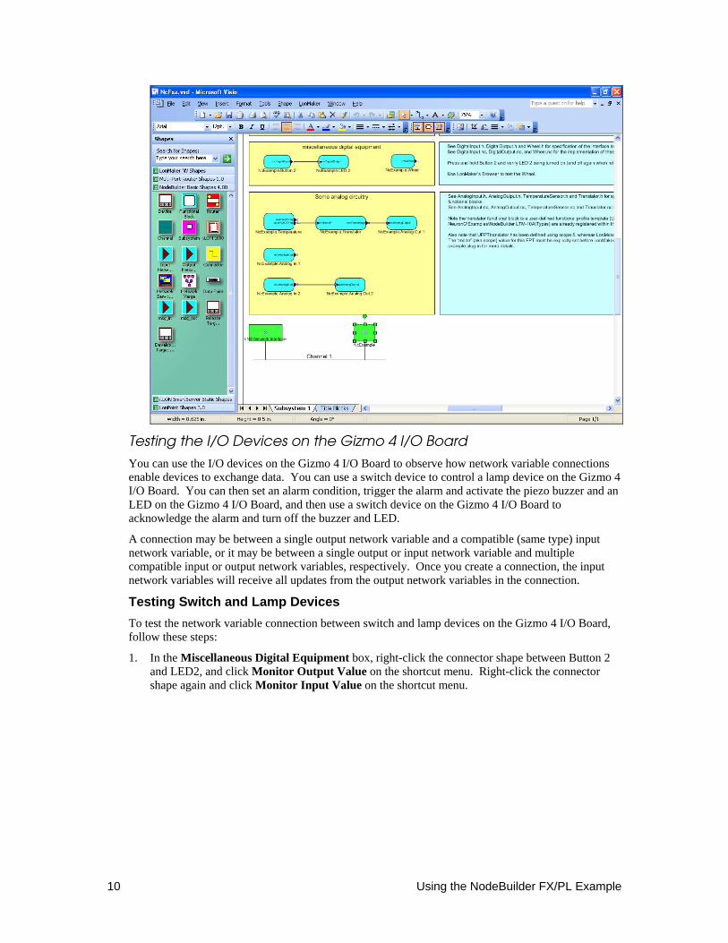
Testing the I/O Devices on the Gizmo 4 I/O Board
You can use the I/O devices on the Gizmo 4 I/O Board to observe how network variable connections enable devices to exchange data. You can use a switch device to control a lamp device on the Gizmo 4 I/O Board. You can then set an alarm condition, trigger the alarm and activate the piezo buzzer and an LED on the Gizmo 4 I/O Board, and then use a switch device on the Gizmo 4 I/O Board to acknowledge the alarm and turn off the buzzer and LED.
A connection may be between a single output network variable and a compatible (same type) input network variable, or it may be between a single output or input network variable and multiple compatible input or output network variables, respectively. Once you create a connection, the input network variables will receive all updates from the output network variables in the connection.
Testing Switch and Lamp Devices To test the network variable connection between switch and lamp devices on the Gizmo 4 I/O Board, follow these steps:
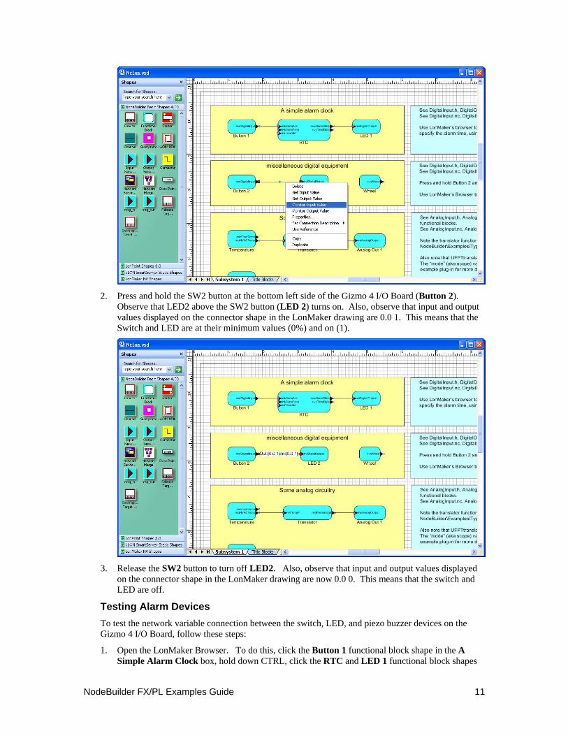
1. In the Miscellaneous Digital Equipment box, right-click the connector shape between Button 2 and LED2, and click Monitor Output Value on the shortcut menu. Right-click the connector shape again and click Monitor Input Value on the shortcut menu.
NodeBuilder FX/PL Examples Guide 11
2. Press and hold the SW2 button at the bottom left side of the Gizmo 4 I/O Board (Button 2).
Observe that LED2 above the SW2 button (LED 2) turns on. Also, observe that input and output values displayed on the connector shape in the LonMaker drawing are 0.0 1. This means that the Switch and LED are at their minimum values (0%) and on (1).
3. Release the SW2 button to turn off LED2. Also, observe that input and output values displayed
on the connector shape in the LonMaker drawing are now 0.0 0. This means that the switch and LED are off.
Testing Alarm Devices To test the network variable connection between the switch, LED, and piezo buzzer devices on the Gizmo 4 I/O Board, follow these steps:
1. Open the LonMaker Browser. To do this, click the Button 1 functional block shape in the A Simple Alarm Clock box, hold down CTRL, click the RTC and LED 1 functional block shapes
12 Using the NodeBuilder FX/PL Example
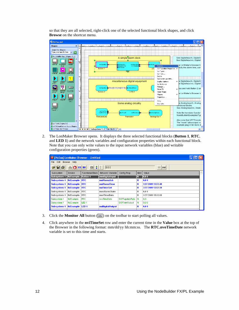
so that they are all selected, right-click one of the selected functional block shapes, and click Browse on the shortcut menu.
2. The LonMaker Browser opens. It displays the three selected functional blocks (Button 1, RTC,
and LED 1) and the network variables and configuration properties within each functional block. Note that you can only write values to the input network variables (blue) and writable configuration properties (green).
3. Click the Monitor All button ( ) on the toolbar to start polling all values.
4. Click anywhere in the nviTimeSet row and enter the current time in the Value box at the top of the Browser in the following format: mm/dd/yy hh:mm:ss. The RTC.nvoTimeDate network variable is set to this time and starts.
NodeBuilder FX/PL Examples Guide 13
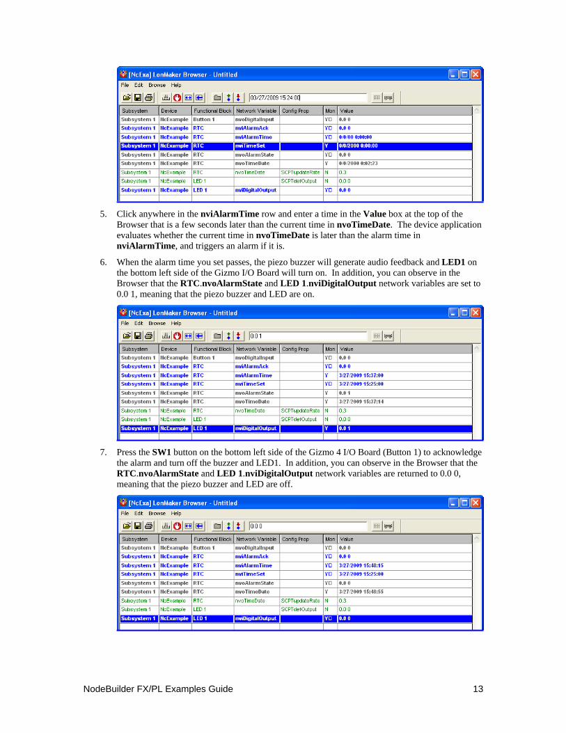
5. Click anywhere in the nviAlarmTime row and enter a time in the Value box at the top of the
Browser that is a few seconds later than the current time in nvoTimeDate. The device application evaluates whether the current time in nvoTimeDate is later than the alarm time in nviAlarmTime, and triggers an alarm if it is.
6. When the alarm time you set passes, the piezo buzzer will generate audio feedback and LED1 on the bottom left side of the Gizmo I/O Board will turn on. In addition, you can observe in the Browser that the RTC.nvoAlarmState and LED 1.nviDigitalOutput network variables are set to 0.0 1, meaning that the piezo buzzer and LED are on.
7. Press the SW1 button on the bottom left side of the Gizmo 4 I/O Board (Button 1) to acknowledge
the alarm and turn off the buzzer and LED1. In addition, you can observe in the Browser that the RTC.nvoAlarmState and LED 1.nviDigitalOutput network variables are returned to 0.0 0, meaning that the piezo buzzer and LED are off.

14 Using the NodeBuilder FX/PL Example
Creating the Example Device Application This section details how to create the NcExample device application from scratch. It describes how each part of the example was developed using the NodeBuilder tool and the LonMaker tool. The example is divided into the nine steps, which introduce different parts of the device development process. You should complete these steps in order because each step assumes that you have successfully completed the previous one. The nine steps to creating the NcExample device application are as follows:
1. Create the LonMaker network, NodeBuilder project, and NodeBuilder device template. 2. Configure the Node Object. 3. Add digital I/O. 4. Implement analog inputs. 5. Implement a simple type translator. 6. Enhance the type translator. 7. Implement the temperature sensor. 8. Implement the real-time clock. 9. Implement the wheel input
Note: This section includes a number of code examples. Many of these examples show code that is generated by the Code Wizard as well as the code to be added. In these examples, code that is generated by the Code Wizard is shown in italics and code which has been added is shown in bold. See the Neuron C Programmer’s Guide and Neuron C Reference Guide for more information on programming in Neuron C.
Step 1: Creating the NodeBuilder Project
In this step, you will create a LonMaker network that contains the device to be developed, create the NodeBuilder project, and create the NodeBuilder device template. To accomplish this, follow these steps:
1. Start the LonMaker tool and create a new LonMaker network named NcExa. Ensure that the LonMaker tool is attached to the network and in the OnNet management mode. See the LonMaker User’s Guide for more information on creating and opening a LonMaker network.
2. Drag the Development Target Device shape from the NodeBuilder Basic Shapes stencil to the LonMaker drawing. The LonMaker New Device Wizard opens.
3. Choose a name for the new device, set Commission Device, and then click Next. The second window of the New Device Wizard opens.
4. Click the Start NodeBuilder button. The NodeBuilder Project Manager appears. When prompted, indicate that you want to create a new NodeBuilder project. The New NodeBuilder Project Wizard opens.
5. Name the new NodeBuilder project NcExa (this will be the default name if you named the LonMaker network this) and click Next. The Project Default Setting window opens.
6. In the Project Default Settings window, add the location of the Gizmo 4 utility files (e.g., Gizmo4.h) to Include Search Path. By default, the Gizmo 4 utility files are located in the LonWorks\NeuronC\Examples\NodeBuilder LTM-10A\NcExample folder. Set Run NodeBuilder device template wizard and click Next. The Device Template Wizard opens.
7. In the first window of the Device Template Wizard, name the new Device Template NcExample. Click Next. The Program ID window opens.
8. Leave automatic Program ID management enabled and use the Standard Program ID Calculator to generate a Program ID. The example provided with the NodeBuilder project uses 9F:FF:FF:05:00:8A:04:00, but the Program ID you use should use your company’s manufacturer ID. See Specifying the Program ID in Chapter 5 of the NodeBuilder User’s Guide for more information about the Standard Program ID Calculator. When you build you will get a

NodeBuilder FX/PL Examples Guide 15
warning that you have a mismatch between the Program ID and the transceiver type. For purposes of the example, you can ignore this warning. If you want to change the Program ID to the appropriate transceiver value, you must set the scope of the resource file created in Step 5: Implementing a Simple Type Translator to 4 so that the Program ID of the resource file set will match the Program ID of the device. Click Next. The Target Platforms window opens.
9. Set the development target hardware to LTM-10A RAM, and the release target hardware to LTM-10A FLASH. See Creating Hardware Templates in Chapter 5 of the NodeBuilder User’s Guide for more information about hardware templates. Select the Run NodeBuilder Code Wizard check box and then click Finish. The NodeBuilder Code Wizard opens.
Step 2: Configuring the Node Object
You can create an empty but fully functioning LONWORKS device with just a Node Object functional block. The Node Object functional block is used by network tools to manage all the functional blocks on a device. In this step, you will use the Code Wizard to configure the device’s Node Object functional block and add code to initialize the Gizmo 4 I/O Board.
1. Click Generate and Close. The Code Wizard generates code and returns you to the NodeBuilder Project Manager.
2. Double-click the common.h file contained in the NcExample device template in the Project pane to open it. Add the following line at the top of the list of include files:
#include "Gizmo4.h" This statement makes the Gizmo 4 utility functions and I/O declarations available to all components of the example application. You must have included the folder containing the Gizmo 4 header files in Include Search Path. If you did not, right-click the device template, select Settings from the shortcut menu, open the Paths tab, and update Include Search Path.
3. In NxExample.nc, in the "when ( reset )" step, add the following lines shown in bold: when (reset) { GizmoReset(); GizmoBuzz(TRUE); GizmoDisplayString(2,0, "Echelon NEURON C"); GizmoDisplayString(0,1, "Example Application"); initAllFblockData(); executeOnEachFblock(FBC_WHEN_RESET); GizmoBuzz(FALSE); }
This code change initializes the Gizmo 4 I/O Board.
4. Save the file by selecting Save from the File menu.
5. Right-click the Development folder and then select Build from the shortcut menu. This builds only the development target which is all that is necessary for this example.
6. Once the build has completed, click the LonMaker tool Taskbar button in the Taskbar to return to the LonMaker tool. The New Device Wizard opened in Step 1: Creating the NodeBuilder Project will still be open.
7. In the NodeBuilder Device Template property, select the NcExample NodeBuilder device template.
8. Continue through the New Device Wizard in the LonMaker tool (see the LonMaker User’s Guide for more information). Set Load Application Image, and set State to Online.
When prompted, press the service pin on the LTM-10A Platform. The application, including the Node Object functional block and the Gizmo utilities, is loaded into the device. The application download takes up to 30 seconds.
16 Using the NodeBuilder FX/PL Example
Now that you have added the device to the LonMaker drawing and loaded the device with its application, the NodeBuilder Project Manager and the LonMaker tool will automatically load new builds of the application into the device.
9. The Gizmo display shows an “Echelon NEURON C Example Application” message after loading and commissioning has been completed.
10. Use the LonMaker tool to test the device. For example, you can add a Node Object functional block and confirm that it has the appropriate network variables and configuration properties.
Step 3: Adding Digital I/O
You can add digital input and output functionality to your device. In this step, you will add a pair of digital actuators and sensor functional blocks to the device, and connect them using the LonMaker tool. Once you complete this step, you can use the buttons on the Gizmo 4 to turn on the LEDs.
After completing this step, you will have a fully functioning LONWORKS device. This step and the functional blocks added in this step are kept simple in order to focus on the essential steps. More sophisticated examples follow in subsequent steps.
1. Click the NodeBuilder tool Taskbar button in the Taskbar to return to the NodeBuilder Project Manager.
2. Right-click the NcExample device template and select Code Wizard from the shortcut menu. The Code Wizard opens.
3. Right-click the Functional Blocks folder and select Add Functional Block from the shortcut menu. The Add Functional Block dialog opens.
4. Add an array of two SFPTopenLoopSensor functional blocks to the device. Name the functional blocks DigitalInput. These two functional blocks will be used to control the two push-buttons on the Gizmo 4.
5. Open the DigitalInput functional block’s Mandatory NVs folder, right-click the network variable contained in the folder, and select Properties from the shortcut menu. The NV Properties dialog opens.
6. Rename the network variables to nvoDigitalInput, and set the type to SNVT_switch. The network variable is implemented as an array of size 2. These network variables will be used to send the value of the digital input on the network (for example, whether the button is being pressed).
7. Repeat steps 3 and 4, but add an array of two SFPTopenLoopActuator functional blocks, and name them DigitalOutput. These functional blocks will be used to control the two LEDs on the Gizmo 4.
8. Repeat steps 5 and 6 but rename the DigitalOutput functional block’s mandatory network variable to nviDigitalOutput, and change the type to SNVT_switch. These two network variables will be used to receive values from the network to drive the LEDs (for example, turn them on and off).
9. Right-click the DigitalOutput functional block’s Optional CPs folder and select Implement Optional CP from the shortcut menu. The Implement Optional CP dialog opens.
10. Select nciDefault from the FPT Member Name dialog to implement this configuration property. Name the configuration property cpDigitalDefault. A single configuration property will be created for each member of the functional block array (the Static CP option is used to create a single configuration property that applies to all functional blocks in the array; this option is discussed in Step 4: Implementing Analog Inputs).
This configuration property will be used to control the initial state of the physical output lines after power-up or reset. Since it is applied to an actuator, the type of this configuration property is the
NodeBuilder FX/PL Examples Guide 17
same as the type of the primary input network variable of the functional block (nviDigitalOutput).
11. Click Generate and Close.
12. Open the device template’s Source Files folder and open ncexample.h by double clicking it. Add the following lines of code shown in bold:
#ifndef _NcExample_H_ #define _NcExample_H_ #define SWITCH_ON 0x01 #define SWITCH_OFF 0x00
This code defines enumerations to use for on and off values for the buttons and LEDs.
13. Open DigitalOutput.nc from the Source Files folder and add the following lines of code shown in bold to the DigitalOutputProcessNV() method:
void DigitalOutputprocessNV(void) { // drive the LED as appropriate: GizmoSetLed(deviceState.nvArrayIndex, nviDigitalOutput[deviceState.nvArrayIndex].state); }
This code causes the LED to be updated whenever the input network variable on the associated DigitalOutput functional block receives an update.
14. Open the DigitalInput.nc file from the Source Files folder and add the following lines of code:
void setDOutValue(unsigned uIndex) { // set the nvo to reflect the input line state. if (fblockNormalNotLockedOut(DigitalInput[uIndex]::global_index)) { nvoDigitalInput[uIndex].state = input_value ? SWITCH_OFF : SWITCH_ON; } } when (io_changes(ioButton1)) { setDOutValue(0); } when (io_changes(ioButton2)) { setDOutValue(1); }
This code causes the output network variables on the DigitalInput functional blocks to be updated whenever the value from the hardware (for example, the push-buttons) changes.
The fblockNormalNotLockedOut() function ensures that the functional block is enabled. Alternatively, the following clause can also be used for the argument of the fblockNormalNotLockedOut() function to retrieve the current functional block index:
fblock_index_map[nv_table_index(nvoDigitalInput[uIndex])]
The DigitalInput[uIndex]::global_index clause is used to demonstrate the scope operator (‘::’), and because this clause is more efficient.
15. Open DigitalOutput.nc from the Source Files folder. Add the following code in bold to the FBC_WHEN_RESET else-if statement:
else if ((TFblock_command)iCommand == FBC_WHEN_RESET) {
18 Using the NodeBuilder FX/PL Example
// initialize output lines: GizmoSetLed(0, DigitalOutput[0]::cpDigitalDefault.state); GizmoSetLed(1, DigitalOutput[1]::cpDigitalDefault.state); setLockedOutBit(uFblockIndex, FALSE); } else if ((TFblock_command)iCommand == FBC_DISABLED)
This code causes LEDs to be set to the value specified in the cpDigitalDefault configuration property when the device is reset.
16. Build the development target. To do this, right click the Development target, and then click Build on the shortcut menu. The LonMaker tool automatically reloads the application into the device.
17. Click the LonMaker tool Taskbar button in the Taskbar to return to the LonMaker tool.
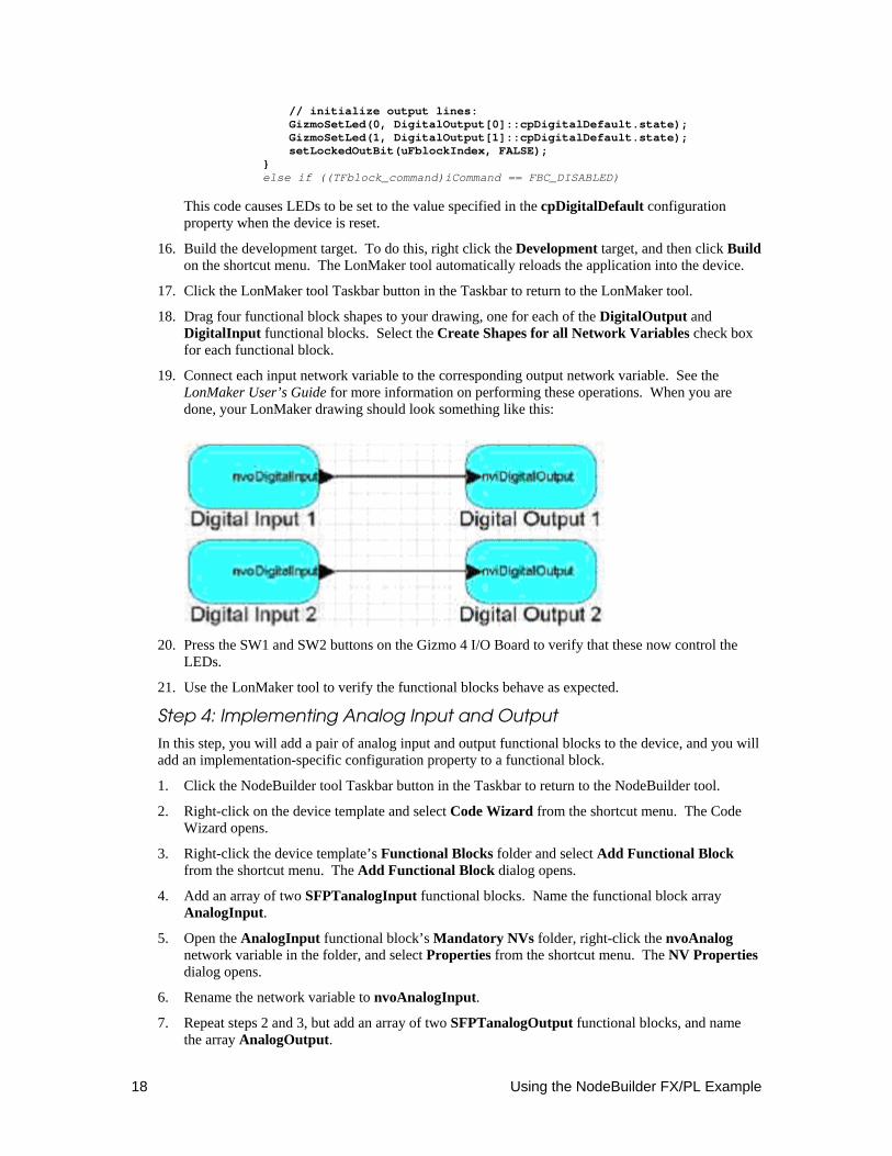
18. Drag four functional block shapes to your drawing, one for each of the DigitalOutput and DigitalInput functional blocks. Select the Create Shapes for all Network Variables check box for each functional block.
19. Connect each input network variable to the corresponding output network variable. See the LonMaker User’s Guide for more information on performing these operations. When you are done, your LonMaker drawing should look something like this:
20. Press the SW1 and SW2 buttons on the Gizmo 4 I/O Board to verify that these now control the
LEDs.
21. Use the LonMaker tool to verify the functional blocks behave as expected.
Step 4: Implementing Analog Input and Output
In this step, you will add a pair of analog input and output functional blocks to the device, and you will add an implementation-specific configuration property to a functional block.
1. Click the NodeBuilder tool Taskbar button in the Taskbar to return to the NodeBuilder tool.
2. Right-click on the device template and select Code Wizard from the shortcut menu. The Code Wizard opens.
3. Right-click the device template’s Functional Blocks folder and select Add Functional Block from the shortcut menu. The Add Functional Block dialog opens.
4. Add an array of two SFPTanalogInput functional blocks. Name the functional block array AnalogInput.
5. Open the AnalogInput functional block’s Mandatory NVs folder, right-click the nvoAnalog network variable in the folder, and select Properties from the shortcut menu. The NV Properties dialog opens.
6. Rename the network variable to nvoAnalogInput.
7. Repeat steps 2 and 3, but add an array of two SFPTanalogOutput functional blocks, and name the array AnalogOutput.
NodeBuilder FX/PL Examples Guide 19
8. Repeat steps 3 and 4, but rename the nviAnalog network variable to nviAnalogOutput.
9. Right-click the AnalogInput functional block’s Implementation-specific CPs folder and select Add CP from the shortcut menu. The Add Configuration Property dialog opens.
10. Add an implementation-specific SCPTupdateRate configuration property. Name the new configuration property cpUpdateRate. Set Static CP for this configuration property; this will cause a single configuration property to be added that applies to all functional blocks in the AnalogInput functional block array. Set Initial Value to 5. This configuration property will be used to specify how often each AnalogInput functional block will read the analog-to-digital converter (ADC) hardware inputs.
Setting the InitialValue field to 5 will cause the value of this configuration property to be set to 5 when the application is loaded into the device. The value of "5" is the unscaled value, representing 500ms or 0.5s.
11. Click OK.
12. Click Generate and Close.
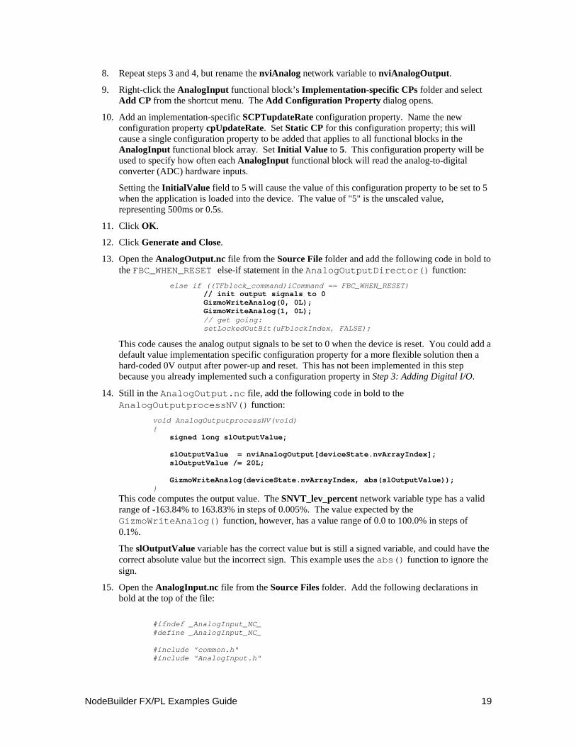
13. Open the AnalogOutput.nc file from the Source File folder and add the following code in bold to the FBC_WHEN_RESET else-if statement in the AnalogOutputDirector() function:
else if ((TFblock_command)iCommand == FBC_WHEN_RESET) // init output signals to 0 GizmoWriteAnalog(0, 0L); GizmoWriteAnalog(1, 0L); // get going: setLockedOutBit(uFblockIndex, FALSE);
This code causes the analog output signals to be set to 0 when the device is reset. You could add a default value implementation specific configuration property for a more flexible solution then a hard-coded 0V output after power-up and reset. This has not been implemented in this step because you already implemented such a configuration property in Step 3: Adding Digital I/O.
14. Still in the AnalogOutput.nc file, add the following code in bold to the AnalogOutputprocessNV() function:
void AnalogOutputprocessNV(void) { signed long slOutputValue; slOutputValue = nviAnalogOutput[deviceState.nvArrayIndex]; slOutputValue /= 20L; GizmoWriteAnalog(deviceState.nvArrayIndex, abs(slOutputValue)); }
This code computes the output value. The SNVT_lev_percent network variable type has a valid range of -163.84% to 163.83% in steps of 0.005%. The value expected by the GizmoWriteAnalog() function, however, has a value range of 0.0 to 100.0% in steps of 0.1%.
The slOutputValue variable has the correct value but is still a signed variable, and could have the correct absolute value but the incorrect sign. This example uses the abs() function to ignore the sign.
15. Open the AnalogInput.nc file from the Source Files folder. Add the following declarations in bold at the top of the file:
#ifndef _AnalogInput_NC_ #define _AnalogInput_NC_ #include "common.h" #include "AnalogInput.h"
20 Using the NodeBuilder FX/PL Example
#define AI_FILTERSIZE 4 #define AI_CHANNELS AnalogInput_FBLOCK_COUNT mtimer ai_timer; // the buffer for the averaging filter: unsigned long ai_rawdata[AI_CHANNELS][AI_FILTERSIZE]; // recent value (required to detect changes for minimum NV updates) unsigned long ai_rawrecent[AI_CHANNELS]; //{{NodeBuilder Code Wizard Start
The Gizmo 4's PIC controller does not provide an interrupt upon the availability of new analog data. Therefore, this example reads both channels every cpUpdateRate interval, which defaults to 1 minute (the PIC converts every 100ms). The minimum sample rate is 0.1s, which matches the PIC controller's real sample rate. This example averages the last AI_FILTERSIZE values obtained for an improved signal quality, where the filter size defaults to 4 and should not be less than two. This implementation will only update the output network variable if the value has been changed.
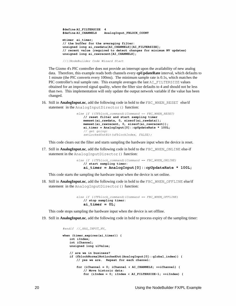
16. Still in AnalogInput.nc, add the following code in bold to the FBC_WHEN_RESET else/if statement in the AnalogInputDirector() function:
else if ((TFblock_command)iCommand == FBC_WHEN_RESET) // reset filter and start sampling timer memset(ai_rawdata, 0, sizeof(ai_rawdata)); memset(ai_rawrecent, 0, sizeof(ai_rawrecent)); ai_timer = AnalogInput[0]::cpUpdateRate * 100L; // get going: setLockedOutBit(uFblockIndex, FALSE);
This code clears out the filter and starts sampling the hardware input when the device is reset.
17. Still in AnalogInput.nc, add the following code in bold to the FBC_WHEN_ONLINE else-if statement in the AnalogInputDirector() function:
else if ((TFblock_command)iCommand == FBC_WHEN_ONLINE) // start sampling timer: ai_timer = AnalogInput[0]::cpUpdateRate * 100L;
This code starts the sampling the hardware input when the device is set online.
18. Still in AnalogInput.nc, add the following code in bold to the FBC_WHEN_OFFLINE else/if statement in the AnalogInputDirector() function:
else if ((TFblock_command)iCommand == FBC_WHEN_OFFLINE) // stop sampling timer: ai_timer = 0L;
This code stops sampling the hardware input when the device is set offline.
19. Still in AnalogInput.nc, add the following code in bold to process expiry of the sampling timer:
#endif //_HAS_INPUT_NV_ when (timer_expires(ai_timer)) { int iIndex; int iChannel; unsigned long ulValue; // are we in business? if (fblockNormalNotLockedOut(AnalogInput[0]::global_index)) { // yes we are. Repeat for each channel: for (iChannel = 0; iChannel < AI_CHANNELS; ++iChannel) { // Move historic data: for (iIndex = 0; iIndex < AI_FILTERSIZE-1; ++iIndex) {
NodeBuilder FX/PL Examples Guide 21
ai_rawdata[iChannel][iIndex] = ai_rawdata[iChannel][iIndex + 1]; } // fetch current value (store in filter history and also // use current value to initialize current result ulValue = ai_rawdata[iChannel][AI_FILTERSIZE-1] = GizmoReadAnalog(iChannel); // compute average over averaging window: for (iIndex = 0; iIndex < AI_FILTERSIZE-1; ++iIndex) { ulValue += ai_rawdata[iChannel][iIndex]; } // now we've got the sum, let's divide in a reasonable // way. That is, we divide and round if appropriate: if ((ulValue % AI_FILTERSIZE) >= (AI_FILTERSIZE / 2)) { ulValue = ulValue / AI_FILTERSIZE + 1L; } else { ulValue /= AI_FILTERSIZE; } // has it changed? if (ulValue != ai_rawrecent[iChannel]) { // it has indeed. Update history and network variable ai_rawrecent[iChannel] = ulValue; nvoAnalogInput[iChannel] = ((SNVT_lev_percent)ulValue)* 20L; } } // next channel } // not in business // re-load timer. We do not use auto-reloading ("mtimer // repeating...") because we want the update frequency to be // adjustable through cpUpdateRate. ai_timer = AnalogInput[0]::cpUpdateRate * 100L; }
20. Build the development target. To do this, right click the Development target, and then click Build on the shortcut menu. The LonMaker tool automatically loads the new application into the device hardware.
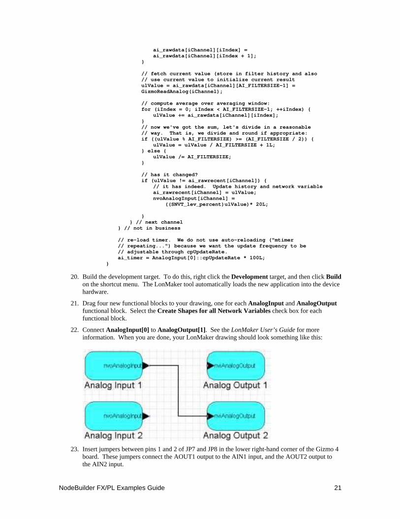
21. Drag four new functional blocks to your drawing, one for each AnalogInput and AnalogOutput functional block. Select the Create Shapes for all Network Variables check box for each functional block.
22. Connect AnalogInput[0] to AnalogOutput[1]. See the LonMaker User’s Guide for more information. When you are done, your LonMaker drawing should look something like this:
23. Insert jumpers between pins 1 and 2 of JP7 and JP8 in the lower right-hand corner of the Gizmo 4
board. These jumpers connect the AOUT1 output to the AIN1 input, and the AOUT2 output to the AIN2 input.
22 Using the NodeBuilder FX/PL Example
24. Browse the Analog Output 1 and Analog Input 2 functional blocks using the LonMaker Browser. Verify that an update to the nviAnalogOutput network variable on Analog Output 1 gets reflected in the nvoAnalogInput network variable on Analog Input 2. Allow a generous conversion error—the Gizmo 4 I/O Board has a 10-bit ADC and an 8-bit DAC converter that are daisy-chained, which causes conversion errors to be multiplied. Also verify correct operation by changing the cpUpdateRate configuration property value, disabling one or more functional blocks in the loop.
Step 5: Implementing a Simple Type Translator
You can create a simple user-defined functional profile (UFPTtranslator) that translates an input network variable of type SNVT_temp_p into an output network variable of type SNVT_lev_percent. This enables you to connect a temperature sensor functional block to the analog output functional blocks on this example device. For more information about the resource editor, see the NodeBuilder Resource Editor User’s Guide.
In this step, you will use the NodeBuilder Resource Editor to create the UFPTtranslator functional profile, which is a basic implementation of a very simple UFPT. You will implement a number of improvements in the design of this UFPT in Step 6: Enhancing the Type Translator.
1. Click the NodeBuilder tool Taskbar button in the Taskbar to return to the NodeBuilder tool. Right-click the NcExample device template and select Code Wizard from the shortcut menu. The Code Wizard opens.
2. In the Resource pane on the left side of the Code Wizard, expand the NcExample functional profile template below the LonWorks\NeuronC\Examples\NodeBuilder LTM-10A\Types folder. The UFPTtranslator functional profile template is displayed.
3. Right-click the UFPTtranslator functional profile and select Open from the shortcut menu. The Modify Resource File Set dialog opens.
4. In the Available Types pane on the left side of this dialog, expand the C:\LonWorks\Types\Standard resource file set folder, and browse to the SNVT_lev_percent network variable type. Drag this network variable type to the UFPTtranslator functional profile’s Mandatory NVs folder in the Functional Profile pane in the center of the dialog. The network variable will be added to the Mandatory NVs folder with the name nviManNV1.
5. Repeat step 4 but add a SNVT_temp_p network variable to the UFPTtranslator functional profile’s Mandatory NVs folder. The new network variable will be named nviManNV2.
6. Click nviManNV1 (the SNVT_lev_percent type network variable added in step 4). The Member Details pane on the right side of the dialog displays the network variable properties. Change Name to nvoPercentage and set Output to indicate that it is an output network variable.
7. Repeat step 6 for nviManNV2 (the SNVT_temp_p type network variable added in step 5). Change Name to nviTempP, set Input to indicate that it is an input network variable, and set Principal NV to make this the functional profile’s principal network variable.
8. Click OK.
9. In the Program Interface pane on the right side of the Code Wizard, right-click the device template’s Functional Blocks folder and add a single UFPTtranslator functional block to the device. Set User-defined and set Scope to 3 in the Add Functional Block dialog to access the new resource file set.
10. Click OK. Click Generate and Close to generate code and exit the Code Wizard.
11. Build the development target. To do this, right click the Development target, and then click Build on the shortcut menu. The LonMaker tool automatically loads the new application into the device hardware.
12. Add the Translator functional block to the LonMaker drawing.
NodeBuilder FX/PL Examples Guide 23
13. Use the LonMaker Browser to browse the translator. Enable monitoring for nvoPercentage, and force nviTempP to several values within and outside the supported range of 0-+30°C.
14. Connect the nvoPercentage output network variable to the input network variable of one of the analog output functional block blocks, connect a multimeter to the relevant analog output.
15. Use the LonMaker Browser to change the nviTempP value, and observe the results.
Step 6: Enhancing the Type Translator
You cam refine and enhance the UFPTtranslator functional profile you defined in Step 5: Implementing a Simple Type Translator. The UFPTtranslator functional profile, with hardcoded input and output limits, is very specialized for this step. In this step, you will add two configuration properties for the input range (replacing the hard-coded minimum and maximum of 0 and 30 degrees Celsius) and two configuration properties to define the minimum and the maximum output signal values.
The configuration properties used for setting the minimum and maximum output will use the SCPTminRnge and SCPTmaxRnge types. These configuration properties are used to limit the minimum value of the primary output network variable for the object.
You need to create your own user-defined configuration property types (UCPTs) because there are no appropriate standard configuration property types (SCPTs) that can limit the input signal range (you can not use SCPThighTemp because this configuration property indicates the high alarm set point for the nvoAlarmAirTemp).
1. Click the NodeBuilder tool Taskbar button in the Taskbar to return to the NodeBuilder tool.
2. Right-click the device template and select Code Wizard from the shortcut menu. The Code Wizard opens.
3. In the Resource pane, browse to the UFPTtranslator functional profile created in Step 5: Implementing a Simple Type Translator. Right-click the functional profile and select Open from the shortcut menu. The Modify Functional Profile Template dialog opens.
4. Select the nviTempP network variable in the Mandatory NVs folder and clear Principal NV.
5. Select the nvoPercentage network variable in the Mandatory NVs folder and set Principal NV. This must be done because the SCPTminRange and SCPTmaxRange standard configuration property types should apply to the principal network variable, as stated in the SCPT description above.
6. In the Available Types pane in the left-hand side of this dialog, expand the LonWorks\types\STANDARD resource file set folder, and browse to the SCPTminRnge configuration property type. Drag the configuration property to the UFPTtranslator functional profile’s Mandatory CPs folder in the Functional Profile pane in the center of this dialog. The configuration property will be added to the Mandatory CPs folder with the name nciManCP1.
7. Repeat step 6 but add a SCPTmaxRnge configuration property to the UFPTtranslator functional profile’s Mandatory CPs folder. The new configuration property will be named nciManCP2.
8. Click nciManCP1 (the SCPTminRnge configuration property added in step 6). The Member Details pane in the right-hand side of the dialog displays the configuration property properties. Change Name to cpTransOutMin.
9. Repeat step 8 for nviManCP2 (the SCPTmaxRnge network variable added in step 7. Change Name to cpTransOutMax.
10. Click OK.
11. Right-click NcExample resource file set’s Configuration Property Types folder and select New CPT from the shortcut menu. The New Configuration Property Type dialog opens.
12. Set CP Name to UCPTminTemp, set Inherited from a network variable.
24 Using the NodeBuilder FX/PL Example
13. Repeat steps 11 and 12, but set CP Name to UCPTmaxTemp.
14. Right-click the UFPTtranslator functional profile and select Open. The Modify Functional Profile Template dialog opens.
15. Add one configuration property of each of the new types to the Mandatory CPs folder. Name them cpTransInMin and cpTransInMax, respectively.
16. Change the “Applies To” setting so that the cpTransInMin/cpTransInMax properties apply to the input network variable, and cpTransOutMin/cpTransOutMax to the output network variable. Click OK.
17. In the Program Interface pane of the Code Wizard, right-click the Translator functional block and select Refresh from the shortcut menu. The functional block will be refreshed to include the new configuration properties that you added to the functional profile.
18. Assign default values to each new configuration property on the Translator functional block. The following values will cause the functional block to behave just as it did after Step 5: Implementing a Simple Type Translator.
cpTransInMin 0 cpTransInMax 3000 cpTransOutMin 0 cpTransOutMax 10000
This step sets defaults for the configuration properties on this device only. This is different than setting the defaults in the functional profile, which will set the defaults for all functional blocks created from that functional profile unless they are otherwise specified.
19. Click Generate and Close.
20. Click Yes to generate resource files.
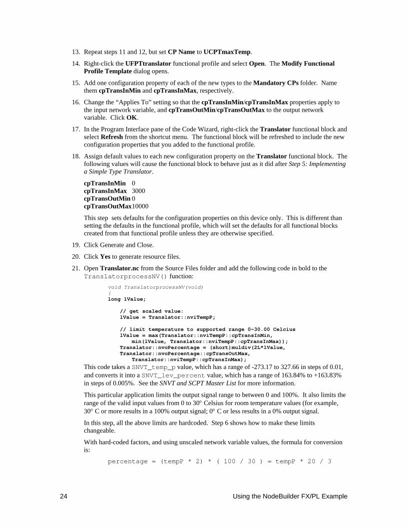
21. Open Translator.nc from the Source Files folder and add the following code in bold to the TranslatorprocessNV() function:
void TranslatorprocessNV(void) { long lValue; // get scaled value: lValue = Translator::nviTempP; // limit temperature to supported range 0-30.00 Celcius lValue = max(Translator::nviTempP::cpTransInMin, min(lValue, Translator::nviTempP::cpTransInMax)); Translator::nvoPercentage = (short)muldiv(2L*lValue, Translator::nvoPercentage::cpTransOutMax, Translator::nviTempP::cpTransInMax);
This code takes a SNVT_temp_p value, which has a range of -273.17 to 327.66 in steps of 0.01, and converts it into a SNVT_lev_percent value, which has a range of 163.84% to +163.83% in steps of 0.005%. See the SNVT and SCPT Master List for more information.
This particular application limits the output signal range to between 0 and 100%. It also limits the range of the valid input values from 0 to 30° Celsius for room temperature values (for example, 30° C or more results in a 100% output signal; 0° C or less results in a 0% output signal.
In this step, all the above limits are hardcoded. Step 6 shows how to make these limits changeable.
With hard-coded factors, and using unscaled network variable values, the formula for conversion is:
percentage = (tempP * 2) * ( 100 / 30 ) = tempP * 20 / 3
NodeBuilder FX/PL Examples Guide 25
The (tempP * 2) term transforms an unscaled SNVT_temp_p value into an equivalent unscaled SNVT_lev_percent value, and the second 100/30 term adjusts so that 30° C converts to 100% of the output signal range. Both terms could be combined in a single factor, but this example uses both for double-precision intermediate results.
22. Build the development target. To do this, right click the Development target, and then click Build on the shortcut menu. The LonMaker tool automatically loads the new application into the device hardware.
23. Add the Translator functional block to the LonMaker drawing.
24. Use the LonMaker Browser to browse the translator. Set the new configuration properties to various values, enable monitoring for nvoPercentage, and force nviTempP to several values within and outside the set range of 0-+30°C. Connect nvoPercentage to the input network variable of one of the analog output functional block blocks, connect a voltmeter to the relevant analog output, use the LonMaker Browser to change the nviTempP value, and observe the results.
Step 7: Implementing the Temperature Sensor
You can implement a standard temperature sensor profile [SFPThvacTempSensor (1040)] to provide a temperature sensor implementation for the Gizmo 4 I/O Board’s temperature sensor hardware. In this step, you will observe the difference between floating-point vs. fixed-point arithmetic in Neuron C. To perform this step, follow these steps:
1. Click the NodeBuilder tool Taskbar button in the Taskbar to return to the NodeBuilder tool. Right-click on the device template and select Code Wizard from the shortcut menu. The Code Wizard opens.
2. Right-click the device template’s Functional Blocks folder and select Add Functional Block from the shortcut menu. The Add Functional Block dialog appears.
3. Add a single SFPThvacTempSensor functional block. Name the new functional block TempSensor. Click OK.
4. Right-click the TempSensor functional block’s Optional NVs folder and select Implement Optional NV from the shortcut menu. The Implement Optional NV dialog appears.
5. Implement the nvoFloatTemp network variable. This network variable has the SNVT_temp_f type. Click OK.
6. Change the names of the three mandatory configuration properties to cpMaxSendTime, cpMinDelta, and cpMinSendTime, respectively.
7. Click Generate and Close.
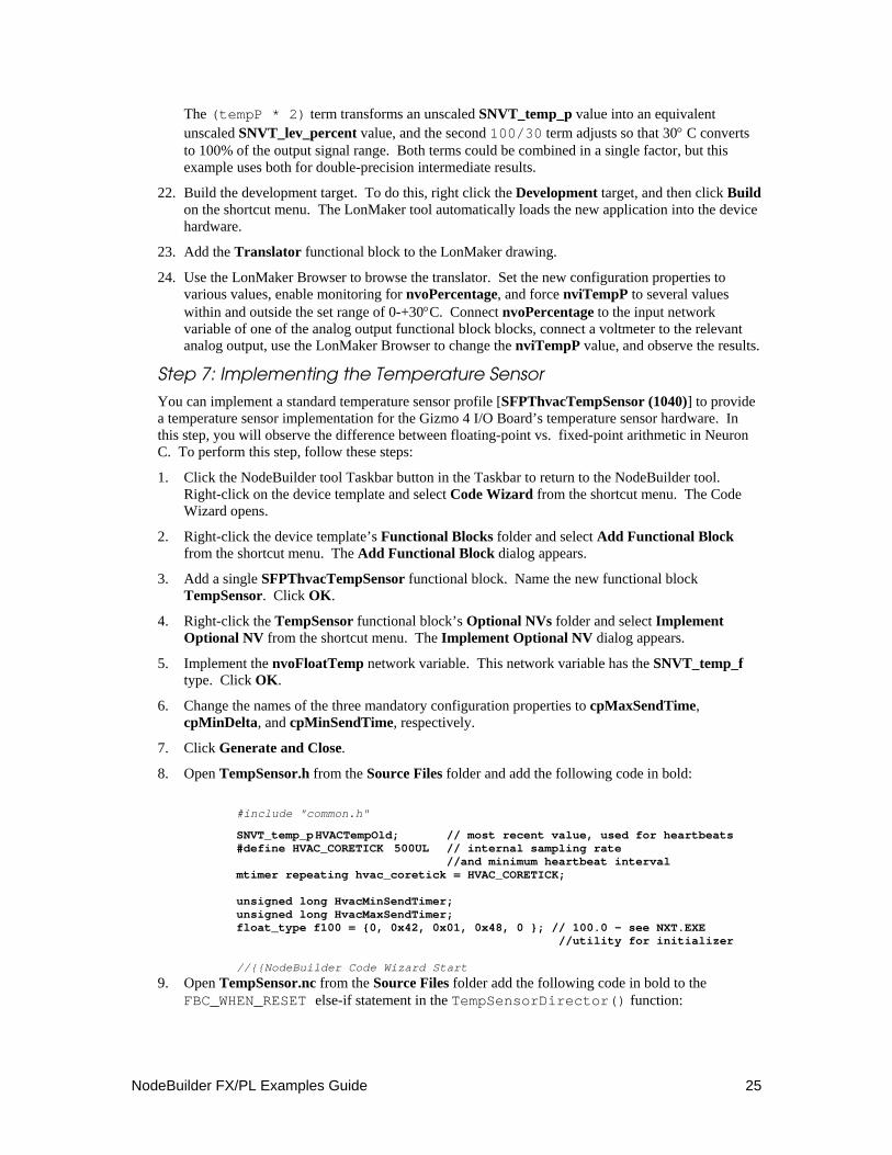
8. Open TempSensor.h from the Source Files folder and add the following code in bold:
#include "common.h"
SNVT_temp_p HVACTempOld; // most recent value, used for heartbeats #define HVAC_CORETICK 500UL // internal sampling rate //and minimum heartbeat interval mtimer repeating hvac_coretick = HVAC_CORETICK; unsigned long HvacMinSendTimer; unsigned long HvacMaxSendTimer; float_type f100 = {0, 0x42, 0x01, 0x48, 0 }; // 100.0 - see NXT.EXE //utility for initializer //{{NodeBuilder Code Wizard Start
9. Open TempSensor.nc from the Source Files folder add the following code in bold to the FBC_WHEN_RESET else-if statement in the TempSensorDirector() function:
26 Using the NodeBuilder FX/PL Example
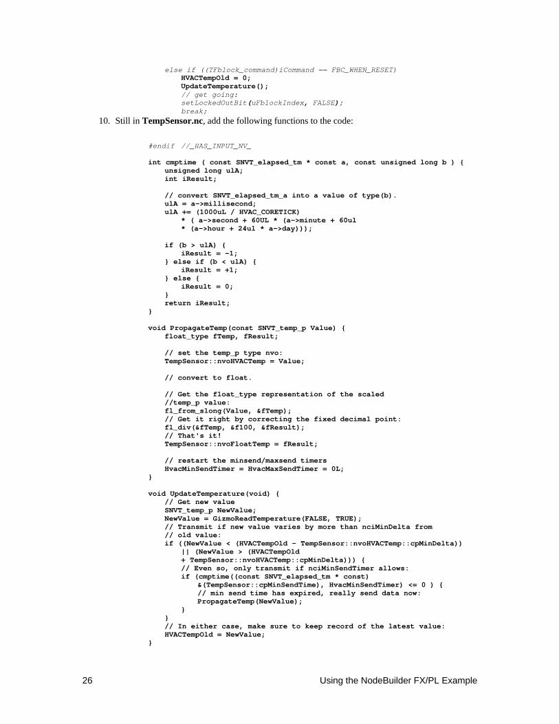
else if ((TFblock_command)iCommand == FBC_WHEN_RESET) HVACTempOld = 0; UpdateTemperature(); // get going: setLockedOutBit(uFblockIndex, FALSE); break;
10. Still in TempSensor.nc, add the following functions to the code:
#endif //_HAS_INPUT_NV_ int cmptime ( const SNVT_elapsed_tm * const a, const unsigned long b ) { unsigned long ulA; int iResult; // convert SNVT_elapsed_tm_a into a value of type(b). ulA = a->millisecond; ulA += (1000uL / HVAC_CORETICK) * ( a->second + 60UL * (a->minute + 60ul * (a->hour + 24ul * a->day))); if (b > ulA) { iResult = -1; } else if (b < ulA) { iResult = +1; } else { iResult = 0; } return iResult; } void PropagateTemp(const SNVT_temp_p Value) { float_type fTemp, fResult; // set the temp_p type nvo: TempSensor::nvoHVACTemp = Value; // convert to float. // Get the float_type representation of the scaled //temp_p value: fl_from_slong(Value, &fTemp); // Get it right by correcting the fixed decimal point: fl_div(&fTemp, &f100, &fResult); // That's it! TempSensor::nvoFloatTemp = fResult; // restart the minsend/maxsend timers HvacMinSendTimer = HvacMaxSendTimer = 0L; } void UpdateTemperature(void) { // Get new value SNVT_temp_p NewValue; NewValue = GizmoReadTemperature(FALSE, TRUE); // Transmit if new value varies by more than nciMinDelta from // old value: if ((NewValue < (HVACTempOld - TempSensor::nvoHVACTemp::cpMinDelta)) || (NewValue > (HVACTempOld + TempSensor::nvoHVACTemp::cpMinDelta))) { // Even so, only transmit if nciMinSendTimer allows: if (cmptime((const SNVT_elapsed_tm * const) &(TempSensor::cpMinSendTime), HvacMinSendTimer) <= 0 ) { // min send time has expired, really send data now: PropagateTemp(NewValue); } } // In either case, make sure to keep record of the latest value: HVACTempOld = NewValue; }
NodeBuilder FX/PL Examples Guide 27
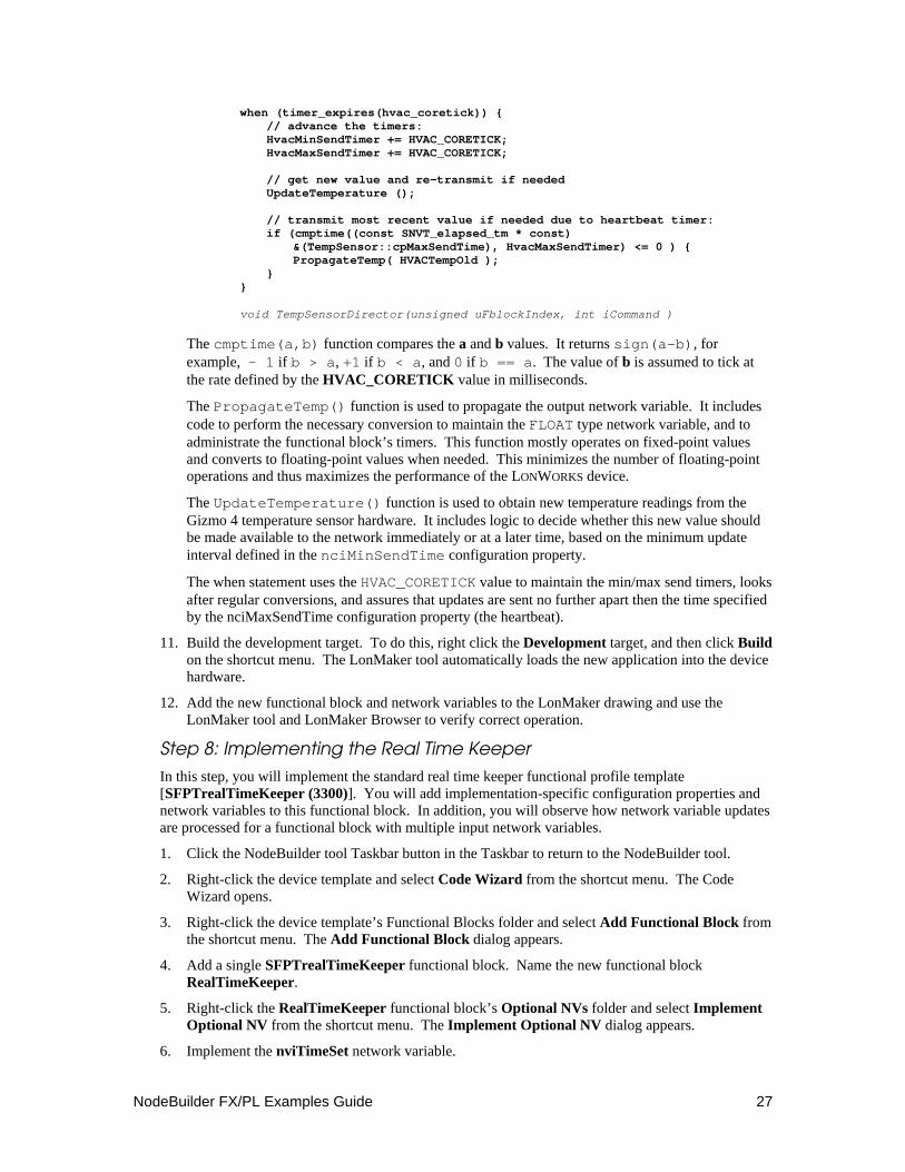
when (timer_expires(hvac_coretick)) { // advance the timers: HvacMinSendTimer += HVAC_CORETICK; HvacMaxSendTimer += HVAC_CORETICK; // get new value and re-transmit if needed UpdateTemperature (); // transmit most recent value if needed due to heartbeat timer: if (cmptime((const SNVT_elapsed_tm * const) &(TempSensor::cpMaxSendTime), HvacMaxSendTimer) <= 0 ) { PropagateTemp( HVACTempOld ); } } void TempSensorDirector(unsigned uFblockIndex, int iCommand )
The cmptime(a,b) function compares the a and b values. It returns sign(a-b), for example, - 1 if b > a, +1 if b < a, and 0 if b == a. The value of b is assumed to tick at the rate defined by the HVAC_CORETICK value in milliseconds.
The PropagateTemp() function is used to propagate the output network variable. It includes code to perform the necessary conversion to maintain the FLOAT type network variable, and to administrate the functional block’s timers. This function mostly operates on fixed-point values and converts to floating-point values when needed. This minimizes the number of floating-point operations and thus maximizes the performance of the LONWORKS device.
The UpdateTemperature() function is used to obtain new temperature readings from the Gizmo 4 temperature sensor hardware. It includes logic to decide whether this new value should be made available to the network immediately or at a later time, based on the minimum update interval defined in the nciMinSendTime configuration property.
The when statement uses the HVAC_CORETICK value to maintain the min/max send timers, looks after regular conversions, and assures that updates are sent no further apart then the time specified by the nciMaxSendTime configuration property (the heartbeat).
11. Build the development target. To do this, right click the Development target, and then click Build on the shortcut menu. The LonMaker tool automatically loads the new application into the device hardware.
12. Add the new functional block and network variables to the LonMaker drawing and use the LonMaker tool and LonMaker Browser to verify correct operation.
Step 8: Implementing the Real Time Keeper
In this step, you will implement the standard real time keeper functional profile template [SFPTrealTimeKeeper (3300)]. You will add implementation-specific configuration properties and network variables to this functional block. In addition, you will observe how network variable updates are processed for a functional block with multiple input network variables.
1. Click the NodeBuilder tool Taskbar button in the Taskbar to return to the NodeBuilder tool.
2. Right-click the device template and select Code Wizard from the shortcut menu. The Code Wizard opens.
3. Right-click the device template’s Functional Blocks folder and select Add Functional Block from the shortcut menu. The Add Functional Block dialog appears.
4. Add a single SFPTrealTimeKeeper functional block. Name the new functional block RealTimeKeeper.
5. Right-click the RealTimeKeeper functional block’s Optional NVs folder and select Implement Optional NV from the shortcut menu. The Implement Optional NV dialog appears.
6. Implement the nviTimeSet network variable.
28 Using the NodeBuilder FX/PL Example
7. Right-click the RealTimeKeeper functional block’s Optional CPs folder and select Implement Optional CP from the shortcut menu. The Implement Optional CP dialog appears.
8. Implement the nciUpdateRate configuration property. Name the new configuration property cpRtcUpdRate. Set Initial Value to 3L.
9. Right-click the RealTimeKeeper functional block’s Implementation-specific NVs folder and select Add NV from the shortcut menu. The Add NV to Functional Block dialog appears.
10. Add a SNVT_time_stamp network variable. Set the direction to Input. Name the new network variable nviAlarmTime.
11. Right-click the RealTimeKeeper functional block’s Implementation-specific NVs folder and select Add Implementation-specific NV from the shortcut menu. The Add NV dialog appears.
12. Add a SNVT_switch network variable. Set the direction to Output. Name the new network variable nvoAlarmState.
13. Right-click the RealTimeKeeper functional block’s Implementation-specific NVs folder and select Add NV from the shortcut menu. The Add NV to Functional Block dialog appears.
14. Add a SNVT_switch network variable. Set the direction to Input. Name the new network variable nviAlarmAck.
15. Click Generate and Close.
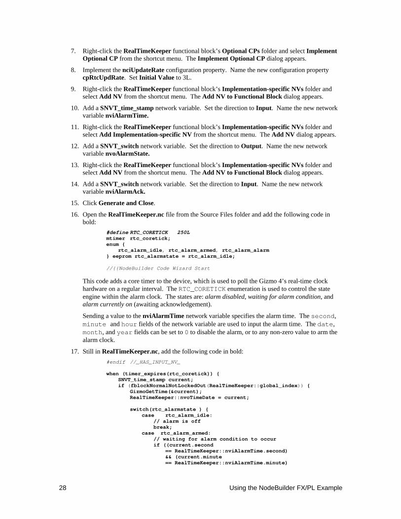
16. Open the RealTimeKeeper.nc file from the Source Files folder and add the following code in bold:
#define RTC_CORETICK 250L mtimer rtc_coretick; enum { rtc_alarm_idle, rtc_alarm_armed, rtc_alarm_alarm } eeprom rtc_alarmstate = rtc_alarm_idle; //{{NodeBuilder Code Wizard Start
This code adds a core timer to the device, which is used to poll the Gizmo 4’s real-time clock hardware on a regular interval. The RTC_CORETICK enumeration is used to control the state engine within the alarm clock. The states are: alarm disabled, waiting for alarm condition, and alarm currently on (awaiting acknowledgement).
Sending a value to the nviAlarmTime network variable specifies the alarm time. The second, minute and hour fields of the network variable are used to input the alarm time. The date, month, and year fields can be set to 0 to disable the alarm, or to any non-zero value to arm the alarm clock.
17. Still in RealTimeKeeper.nc, add the following code in bold: #endif //_HAS_INPUT_NV_ when (timer_expires(rtc_coretick)) { SNVT_time_stamp current; if (fblockNormalNotLockedOut(RealTimeKeeper::global_index)) { GizmoGetTime(¤t); RealTimeKeeper::nvoTimeDate = current; switch(rtc_alarmstate ) { case rtc_alarm_idle: // alarm is off break; case rtc_alarm_armed: // waiting for alarm condition to occur if ((current.second == RealTimeKeeper::nviAlarmTime.second) && (current.minute == RealTimeKeeper::nviAlarmTime.minute)
NodeBuilder FX/PL Examples Guide 29
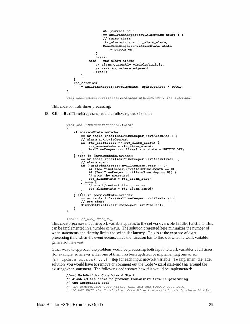
&& (current.hour == RealTimeKeeper::nviAlarmTime.hour) ) { // raise alarm rtc_alarmstate = rtc_alarm_alarm; RealTimeKeeper::nviAlarmState.state = SWITCH_ON; } break; case rtc_alarm_alarm: // alarm currently visible/audible, // awaiting acknowledgement break; } } rtc_coretick = RealTimeKeeper::nvoTimeDate::cpRtcUpdRate * 100UL; } void RealTimeKeeperDirector(unsigned uFblockIndex, int iCommand)
This code controls timer processing.
18. Still in RealTimeKeeper.nc, add the following code in bold:
void RealTimeKeeperprocessNV(void) { if (deviceState.nvIndex == nv_table_index(RealTimeKeeper::nviAlarmAck)) { // alarm acknowledgement: if (rtc_alarmstate == rtc_alarm_alarm) { rtc_alarmstate = rtc_alarm_armed; RealTimeKeeper::nvoAlarmState.state = SWITCH_OFF; } } else if (deviceState.nvIndex == nv_table_index(RealTimeKeeper::nviAlarmTime)) { // alarm spec: if ((RealTimeKeeper::nviAlarmTime.year == 0) && (RealTimeKeeper::nviAlarmTime.month == 0) && (RealTimeKeeper::nviAlarmTime.day == 0)) { // stop the nonsense! rtc_alarmstate = rtc_alarm_idle; } else { // start/restart the nonsense rtc_alarmstate = rtc_alarm_armed; } } else if (deviceState.nvIndex == nv_table_index(RealTimeKeeper::nviTimeSet)) { // set time: GizmoSetTime(&RealTimeKeeper::nviTimeSet); } } #endif //_HAS_INPUT_NV_
This code processes input network variable updates to the network variable handler function. This can be implemented in a number of ways. The solution presented here minimizes the number of when statements and thereby limits the scheduler latency. This is at the expense of extra processing time when the event occurs, since the function has to find out what network variable generated the event.
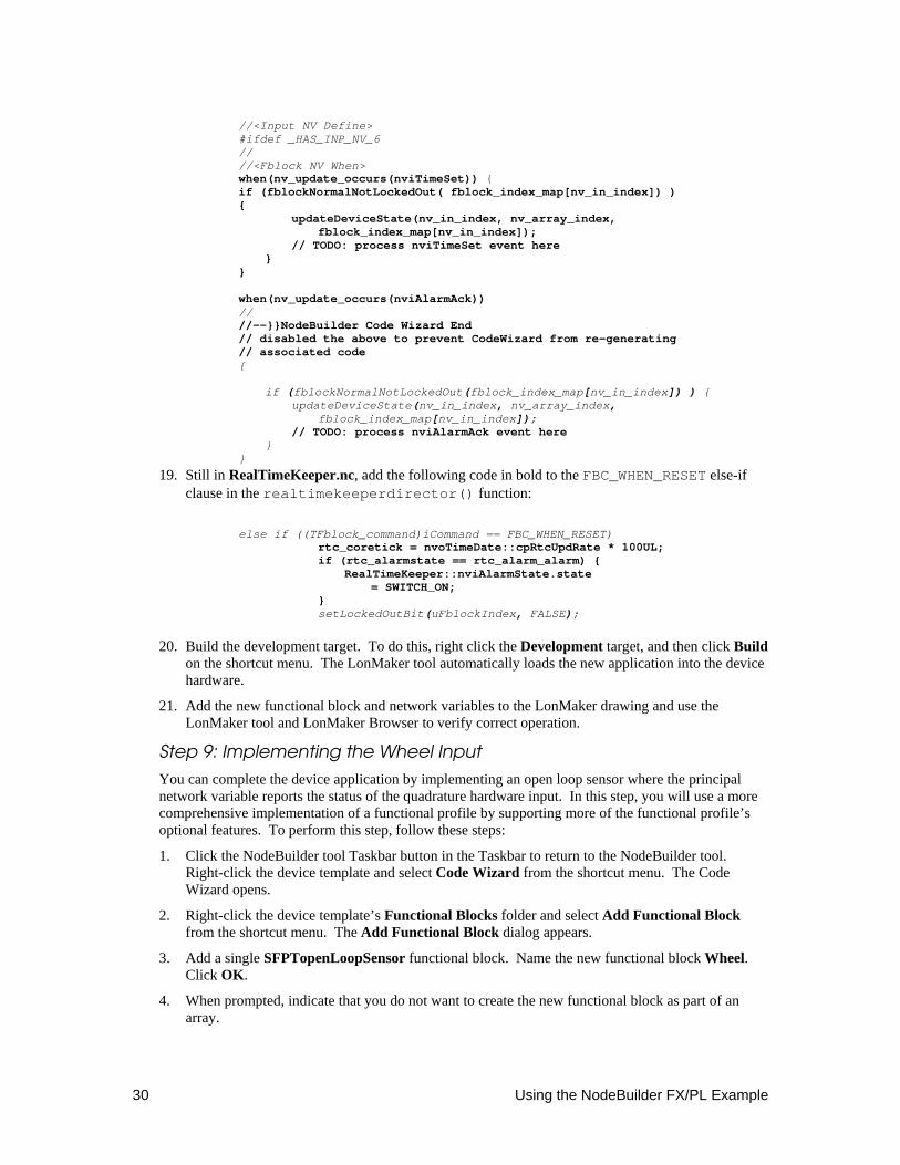
Other ways to approach the problem would be processing both input network variables at all times (for example, whenever either one of them has been updated, or implementing one when (nv_update_occurs(....)) step for each input network variable. To implement the latter solution, you would have to remove or comment out the Code Wizard start/end tags around the existing when statement. The following code shows how this would be implemented:
//--{{NodeBuilder Code Wizard Start // disabled the above to prevent CodeWizard from re-generating // the associated code // the NodeBuilder Code Wizard will add and remove code here. // DO NOT EDIT the NodeBuilder Code Wizard generated code in these blocks!
30 Using the NodeBuilder FX/PL Example
//<Input NV Define> #ifdef _HAS_INP_NV_6 // //<Fblock NV When> when(nv_update_occurs(nviTimeSet)) { if (fblockNormalNotLockedOut( fblock_index_map[nv_in_index]) ) { updateDeviceState(nv_in_index, nv_array_index, fblock_index_map[nv_in_index]); // TODO: process nviTimeSet event here } } when(nv_update_occurs(nviAlarmAck)) // //--}}NodeBuilder Code Wizard End // disabled the above to prevent CodeWizard from re-generating // associated code { if (fblockNormalNotLockedOut(fblock_index_map[nv_in_index]) ) { updateDeviceState(nv_in_index, nv_array_index, fblock_index_map[nv_in_index]); // TODO: process nviAlarmAck event here } }
19. Still in RealTimeKeeper.nc, add the following code in bold to the FBC_WHEN_RESET else-if clause in the realtimekeeperdirector() function:
else if ((TFblock_command)iCommand == FBC_WHEN_RESET) rtc_coretick = nvoTimeDate::cpRtcUpdRate * 100UL; if (rtc_alarmstate == rtc_alarm_alarm) { RealTimeKeeper::nviAlarmState.state = SWITCH_ON; } setLockedOutBit(uFblockIndex, FALSE);
20. Build the development target. To do this, right click the Development target, and then click Build on the shortcut menu. The LonMaker tool automatically loads the new application into the device hardware.
21. Add the new functional block and network variables to the LonMaker drawing and use the LonMaker tool and LonMaker Browser to verify correct operation.
Step 9: Implementing the Wheel Input
You can complete the device application by implementing an open loop sensor where the principal network variable reports the status of the quadrature hardware input. In this step, you will use a more comprehensive implementation of a functional profile by supporting more of the functional profile’s optional features. To perform this step, follow these steps:
1. Click the NodeBuilder tool Taskbar button in the Taskbar to return to the NodeBuilder tool. Right-click the device template and select Code Wizard from the shortcut menu. The Code Wizard opens.
2. Right-click the device template’s Functional Blocks folder and select Add Functional Block from the shortcut menu. The Add Functional Block dialog appears.
3. Add a single SFPTopenLoopSensor functional block. Name the new functional block Wheel. Click OK.
4. When prompted, indicate that you do not want to create the new functional block as part of an array.
NodeBuilder FX/PL Examples Guide 31
5. Open the Wheel functional block’s Mandatory NVs folder. Right-click the nvoValue network variable and select Properties from the shortcut menu. The NV Properties dialog opens.
6. Set NV Type to SNVT_lev_percent and Name to nvoWheel.
7. Right-click the Wheel functional block’s Optional CPs folder and select Implement Optional CP from the shortcut menu. The Implement Optional CP dialog appears.
8. Implement the nciGain configuration property. Name the new configuration property cpWhGain. Set Initializer to {1,1}. This configuration property holds the gain value between the physical input and the nvoWheel network variable.
9. Right-click the Wheel functional block’s Optional CPs folder and select Implement Optional CP from the shortcut menu. The Implement Optional CP dialog appears.
10. Implement the nciLocation configuration property. Name the new configuration property cpWhLocation. This configuration property holds the location of the sensor device.
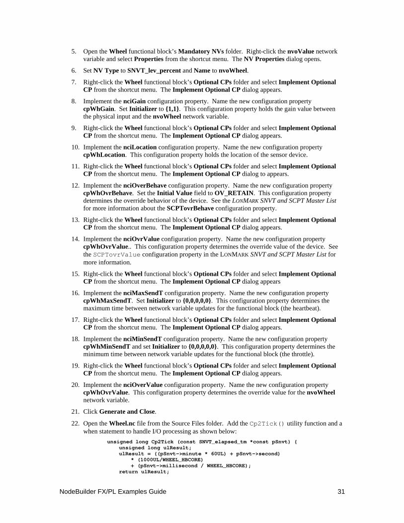
11. Right-click the Wheel functional block’s Optional CPs folder and select Implement Optional CP from the shortcut menu. The Implement Optional CP dialog to appears.
12. Implement the nciOverBehave configuration property. Name the new configuration property cpWhOvrBehave. Set the Initial Value field to OV_RETAIN. This configuration property determines the override behavior of the device. See the LONMARK SNVT and SCPT Master List for more information about the SCPTovrBehave configuration property.
13. Right-click the Wheel functional block’s Optional CPs folder and select Implement Optional CP from the shortcut menu. The Implement Optional CP dialog appears.
14. Implement the nciOvrValue configuration property. Name the new configuration property cpWhOvrValue.. This configuration property determines the override value of the device. See the SCPTovrValue configuration property in the LONMARK SNVT and SCPT Master List for more information.
15. Right-click the Wheel functional block’s Optional CPs folder and select Implement Optional CP from the shortcut menu. The Implement Optional CP dialog appears
16. Implement the nciMaxSendT configuration property. Name the new configuration property cpWhMaxSendT. Set Initializer to {0,0,0,0,0}. This configuration property determines the maximum time between network variable updates for the functional block (the heartbeat).
17. Right-click the Wheel functional block’s Optional CPs folder and select Implement Optional CP from the shortcut menu. The Implement Optional CP dialog appears.
18. Implement the nciMinSendT configuration property. Name the new configuration property cpWhMinSendT and set Initializer to {0,0,0,0,0}. This configuration property determines the minimum time between network variable updates for the functional block (the throttle).
19. Right-click the Wheel functional block’s Optional CPs folder and select Implement Optional CP from the shortcut menu. The Implement Optional CP dialog appears.
20. Implement the nciOverValue configuration property. Name the new configuration property cpWhOvrValue. This configuration property determines the override value for the nvoWheel network variable.
21. Click Generate and Close.
22. Open the Wheel.nc file from the Source Files folder. Add the Cp2Tick() utility function and a when statement to handle I/O processing as shown below:
unsigned long Cp2Tick (const SNVT_elapsed_tm *const pSnvt) { unsigned long ulResult; ulResult = ((pSnvt->minute * 60UL) + pSnvt->second) * (1000UL/WHEEL_HBCORE) + (pSnvt->millisecond / WHEEL_HBCORE); return ulResult;
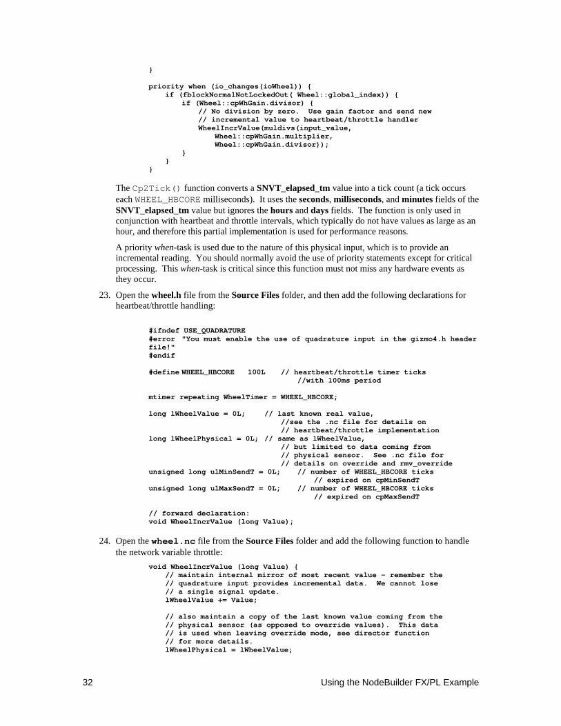
32 Using the NodeBuilder FX/PL Example
} priority when (io_changes(ioWheel)) { if (fblockNormalNotLockedOut( Wheel::global_index)) { if (Wheel::cpWhGain.divisor) { // No division by zero. Use gain factor and send new // incremental value to heartbeat/throttle handler WheelIncrValue(muldivs(input_value, Wheel::cpWhGain.multiplier, Wheel::cpWhGain.divisor)); } } }
The Cp2Tick() function converts a SNVT_elapsed_tm value into a tick count (a tick occurs each WHEEL_HBCORE milliseconds). It uses the seconds, milliseconds, and minutes fields of the SNVT_elapsed_tm value but ignores the hours and days fields. The function is only used in conjunction with heartbeat and throttle intervals, which typically do not have values as large as an hour, and therefore this partial implementation is used for performance reasons.
A priority when-task is used due to the nature of this physical input, which is to provide an incremental reading. You should normally avoid the use of priority statements except for critical processing. This when-task is critical since this function must not miss any hardware events as they occur.
23. Open the wheel.h file from the Source Files folder, and then add the following declarations for heartbeat/throttle handling:
#ifndef USE_QUADRATURE #error "You must enable the use of quadrature input in the gizmo4.h header file!" #endif #define WHEEL_HBCORE 100L // heartbeat/throttle timer ticks //with 100ms period mtimer repeating WheelTimer = WHEEL_HBCORE; long lWheelValue = 0L; // last known real value, //see the .nc file for details on // heartbeat/throttle implementation long lWheelPhysical = 0L; // same as lWheelValue, // but limited to data coming from // physical sensor. See .nc file for // details on override and rmv_override unsigned long ulMinSendT = 0L; // number of WHEEL_HBCORE ticks // expired on cpMinSendT unsigned long ulMaxSendT = 0L; // number of WHEEL_HBCORE ticks // expired on cpMaxSendT // forward declaration: void WheelIncrValue (long Value);
24. Open the wheel.nc file from the Source Files folder and add the following function to handle the network variable throttle:
void WheelIncrValue (long Value) { // maintain internal mirror of most recent value - remember the // quadrature input provides incremental data. We cannot lose // a single signal update. lWheelValue += Value; // also maintain a copy of the last known value coming from the // physical sensor (as opposed to override values). This data // is used when leaving override mode, see director function // for more details. lWheelPhysical = lWheelValue;
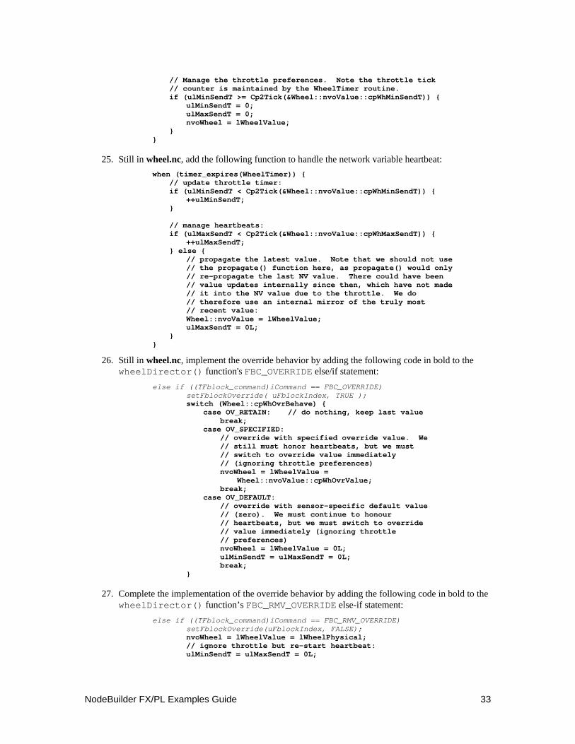
NodeBuilder FX/PL Examples Guide 33
// Manage the throttle preferences. Note the throttle tick // counter is maintained by the WheelTimer routine. if (ulMinSendT >= Cp2Tick(&Wheel::nvoValue::cpWhMinSendT)) { ulMinSendT = 0; ulMaxSendT = 0; nvoWheel = lWheelValue; } }
25. Still in wheel.nc, add the following function to handle the network variable heartbeat: when (timer_expires(WheelTimer)) { // update throttle timer: if (ulMinSendT < Cp2Tick(&Wheel::nvoValue::cpWhMinSendT)) { ++ulMinSendT; } // manage heartbeats: if (ulMaxSendT < Cp2Tick(&Wheel::nvoValue::cpWhMaxSendT)) { ++ulMaxSendT; } else { // propagate the latest value. Note that we should not use // the propagate() function here, as propagate() would only // re-propagate the last NV value. There could have been // value updates internally since then, which have not made // it into the NV value due to the throttle. We do // therefore use an internal mirror of the truly most // recent value: Wheel::nvoValue = lWheelValue; ulMaxSendT = 0L; } }
26. Still in wheel.nc, implement the override behavior by adding the following code in bold to the wheelDirector() function's FBC_OVERRIDE else/if statement:
else if ((TFblock_command)iCommand == FBC_OVERRIDE) setFblockOverride( uFblockIndex, TRUE ); switch (Wheel::cpWhOvrBehave) { case OV_RETAIN: // do nothing, keep last value break; case OV_SPECIFIED: // override with specified override value. We // still must honor heartbeats, but we must // switch to override value immediately // (ignoring throttle preferences) nvoWheel = lWheelValue = Wheel::nvoValue::cpWhOvrValue; break; case OV_DEFAULT: // override with sensor-specific default value // (zero). We must continue to honour // heartbeats, but we must switch to override // value immediately (ignoring throttle // preferences) nvoWheel = lWheelValue = 0L; ulMinSendT = ulMaxSendT = 0L; break; }
27. Complete the implementation of the override behavior by adding the following code in bold to the wheelDirector() function’s FBC_RMV_OVERRIDE else-if statement:
else if ((TFblock_command)iCommand == FBC_RMV_OVERRIDE) setFblockOverride(uFblockIndex, FALSE); nvoWheel = lWheelValue = lWheelPhysical; // ignore throttle but re-start heartbeat: ulMinSendT = ulMaxSendT = 0L;
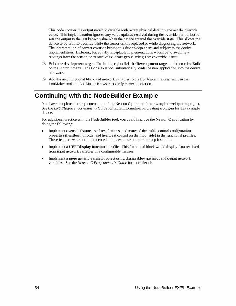
34 Using the NodeBuilder FX/PL Example
This code updates the output network variable with recent physical data to wipe out the override value. This implementation ignores any value updates received during the override period, but re-sets the output to the last known value when the device entered the override state. This allows the device to be set into override while the sensor unit is replaced or while diagnosing the network. The interpretation of correct override behavior is device-dependent and subject to the device implementation. Different, but equally acceptable implementations would be to await new readings from the sensor, or to save value changes during the override state.
28. Build the development target. To do this, right click the Development target, and then click Build on the shortcut menu. The LonMaker tool automatically loads the new application into the device hardware.
29. Add the new functional block and network variables to the LonMaker drawing and use the LonMaker tool and LonMaker Browser to verify correct operation.
Continuing with the NodeBuilder Example You have completed the implementation of the Neuron C portion of the example development project. See the LNS Plug-in Programmer’s Guide for more information on creating a plug-in for this example device.
For additional practice with the NodeBuilder tool, you could improve the Neuron C application by doing the following:
• Implement override features, self-test features, and many of the traffic-control configuration properties (heartbeat, throttle, and heartbeat control on the input side) in the functional profiles. These features were not implemented in this exercise in order to keep it simple.
• Implement a UFPTdisplay functional profile. This functional block would display data received from input network variables in a configurable manner.
• Implement a more generic translator object using changeable-type input and output network variables. See the Neuron C Programmer’s Guide for more details.

www.echelon.com


