
Cat.No.R03E-3
MurataManufacturing Co., Ltd.
NTC/PTC Thermistors for Automotive
• This PDF catalog is downloaded from the website of Murata Manufacturing co., ltd. Therefore, it’s specifications are subject to change or our products in it may be discontinued without advance notice. Please check with our sales representatives or product engineers before ordering.
• This PDF catalog has only typical specifications because there is no space for detailed specifications. Therefore, please approve our product specifications or transact the approval sheet for product specifications before ordering.
!Note R03E.pdf07.3.21

2
3
5
6
4
1
Part Numbering 2
Basic Characteristics of NTC Thermistor 6
Basic Characteristics of POSISTORr 7
NTC Thermistor Chip Type 0402 (1005) Size 8
NTC Thermistor Chip Type 0603 (1608) Size 10
For NTC Thermistors Chip Type Standard Land Pattern Dimensions 11
For NTC Thermistors Chip Type Temperature Characteristics (Center Value) 12
For NTC Thermistors Chip Type Specifications and Test Methods 15
For NTC Thermistors Chip Type !Caution/Notice 17
NTC Thermistor Lead Type for Temperature Sensor 20
For NTC Thermistors Lead Type Temperature Characteristics (Center Value) 21
For NTC Thermistors Lead Type Specifications and Test Methods 22
For NTC Thermistors Lead Type !Caution/Notice 23
PTC Thermistor (POSISTORr) for Overheat Sensing Chip Type 0603 (1608) Size 24
Chip Type of POSISTORr for Overheat Protection Specifications and Test Methods 27
PTC Thermistor (POSISTORr) for Overcurrent Protection Chip Type 0805 (2012) Size 29
Chip Type of POSISTORr for Overheat Protection Specifications and Test Methods 31
For POSISTORr Chip Type !Caution/Notice 33
PTC Thermistor (POSISTORr) for Overcurrent Protection Lead Type 39
POSISTORr Lead Type for Overheat Protection Specifications and Test Methods 49
POSISTORr Lead Type for Overheat Protection !Caution/Notice 52
For NTC Thermistors Chip Type Package 53
For NTC Thermistors Lead Type Package 55
For POSISTORr Chip Type Package 56
For POSISTORr Lead Type Package 57
POSISTORr and "POSISTOR" in this catalog arethe trademarks of Murata Manufacturing Co., Ltd.
CONTENTS
!Note • Please read rating and !CAUTION (for storage, operating, rating, soldering, mounting and handling) in this catalog to prevent smoking and/or burning, etc.• This catalog has only typical specifications because there is no space for detailed specifications. Therefore, please approve our product specifications or transact the approval sheet for product specifications before ordering.
Recycled Paper
1
2
3
4
5
6
• This PDF catalog is downloaded from the website of Murata Manufacturing co., ltd. Therefore, it’s specifications are subject to change or our products in it may be discontinued without advance notice. Please check with our sales representatives or product engineers before ordering.
• This PDF catalog has only typical specifications because there is no space for detailed specifications. Therefore, please approve our product specifications or transact the approval sheet for product specifications before ordering.
!Note R03E.pdf07.3.21
!Note • Please read rating and !CAUTION (for storage, operating, rating, soldering, mounting and handling) in this catalog to prevent smoking and/or burning, etc.• This catalog has only typical specifications because there is no space for detailed specifications. Therefore, please approve our product specifications or transact the approval sheet for product specifications before ordering.
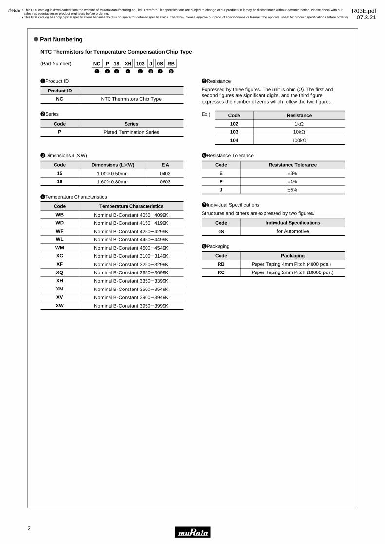
o Part Numbering
qProduct ID
wSeries
yResistance Tolerance
uIndividual Specifications
NTC Thermistors for Temperature Compensation Chip Type
NC NTC Thermistors Chip Type
E
F
J
P
±3%
±1%
±5%
0S
Individual Specifications
Product ID
Code
Code
Series
Resistance Tolerance
Code
(Part Number)
tResistance
Expressed by three figures. The unit is ohm (Ω). The first and second figures are significant digits, and the third figure expresses the number of zeros which follow the two figures.
Structures and others are expressed by two figures.
102
103
104
Ex.)
1kΩ
10kΩ
100kΩ
Code Resistance
for Automotive
iPackaging
RB
RC
Paper Taping 4mm Pitch (4000 pcs.)
Paper Taping 2mm Pitch (10000 pcs.)
Code Packaging
Plated Termination Series
eDimensions (LgW)
15
18
Code Dimensions (LgW)
1.00g0.50mm
1.60g0.80mm
EIA
0402
0603
rTemperature Characteristics
WB
WD
WF
WL
WM
XC
XF
XQ
XH
XM
XV
XW
Code Temperature Characteristics
Nominal B-Constant 4050e4099K
Nominal B-Constant 4150e4199K
Nominal B-Constant 4250e4299K
Nominal B-Constant 4450e4499K
Nominal B-Constant 4500e4549K
Nominal B-Constant 3100e3149K
Nominal B-Constant 3250e3299K
Nominal B-Constant 3650e3699K
Nominal B-Constant 3350e3399K
Nominal B-Constant 3500e3549K
Nominal B-Constant 3900e3949K
Nominal B-Constant 3950e3999K
y
J
e
18
w
P
r
XH
t
103
u
0S
i
RBNC
q
2
• This PDF catalog is downloaded from the website of Murata Manufacturing co., ltd. Therefore, it’s specifications are subject to change or our products in it may be discontinued without advance notice. Please check with our sales representatives or product engineers before ordering.
• This PDF catalog has only typical specifications because there is no space for detailed specifications. Therefore, please approve our product specifications or transact the approval sheet for product specifications before ordering.
!Note R03E.pdf07.3.21

!Note • Please read rating and !CAUTION (for storage, operating, rating, soldering, mounting and handling) in this catalog to prevent smoking and/or burning, etc.• This catalog has only typical specifications because there is no space for detailed specifications. Therefore, please approve our product specifications or transact the approval sheet for product specifications before ordering.
qProduct ID
wSeries
tResistance Tolerance
yIndividual Specifications
NTC Thermistors for Temperature Sensor Lead Type
NT NTC Thermistors
E
F
±3%
±1%
E1
N6
Individual Specifications
Product ID
Code Resistance Tolerance
Code
(Part Number)
rResistance
Expressed by three figures. The unit is ohm (Ω). The first and second figures are significant digits, and the third figure expresses the number of zeros which follow the two figures.
A lead structure and other specifications are expressed by two digits.
202
203
Ex.)
2kΩ
20kΩ
Code Resistance
Bulk
Standard Taping
SS0 Temperature Sensors for Automotive Equipment
Code
uPackaging
A0
B0
Ammo Pack
Bulk
Code Packaging
Series
eTemperature Characteristics
WB
WC
WD
WF
XM
XH
XR
XV
Nominal B-Constant 4050e4099K
Nominal B-Constant 4100e4149K
Nominal B-Constant 4150e4199K
Nominal B-Constant 4250e4299K
Nominal B-Constant 3500e3549K
Nominal B-Constant 3350e3399K
Nominal B-Constant 3700e3749K
Nominal B-Constant 3900e3949K
Code Temperature Characteristics
t
F
w
SS0
e
XH
r
103
y
E1
u
B0NT
q
y
Q
e
18
w
F
r
BB
t
471
u
S2
i
RBPR
q
qProduct ID
wSeries
rTemperature Characteristics
yResistance Tolerance
uIndividual Specifications
PTC Thermistors (POSISTORr) for Overheat Sensing Chip Type
PR PTC Thermistors Chip Type
Q
R
F for Overheat Sensing
AR
AS
BA
BB
BC
BD
BE
BF
BG
Curie Point 120°C
Curie Point 130°C
Curie Point 110°C
Curie Point 100°C
Curie Point 90°C
Curie Point 80°C
Curie Point 70°C
Curie Point 60°C
Curie Point 50°C
Special Tolerance
Special Tolerance
Temperature Characteristics
S2
Individual Specifications
Product ID
Code
Code
Code
Series
Resistance Tolerance
±5°C
±3°C
Sensing Temp. Tolerance
Code
(Part Number)
tResistance
Expressed by three figures. The unit is ohm (Ω). The first and second figures are significant digits, and the third figure expresses the number of zeros which follow the two figures.
471
Ex.)
470Ω
Code Resistance
for Automotive
eDimensions (LgW)
18 1.60g0.80mm
Code Dimensions (LgW)
iPackaging
RB
PackagingCode
Paper Taping (4mm Pitch) (4000 pcs.)
3
• This PDF catalog is downloaded from the website of Murata Manufacturing co., ltd. Therefore, it’s specifications are subject to change or our products in it may be discontinued without advance notice. Please check with our sales representatives or product engineers before ordering.
• This PDF catalog has only typical specifications because there is no space for detailed specifications. Therefore, please approve our product specifications or transact the approval sheet for product specifications before ordering.
!Note R03E.pdf07.3.21

!Note • Please read rating and !CAUTION (for storage, operating, rating, soldering, mounting and handling) in this catalog to prevent smoking and/or burning, etc.• This catalog has only typical specifications because there is no space for detailed specifications. Therefore, please approve our product specifications or transact the approval sheet for product specifications before ordering.
y
M
e
21
w
G
r
AR
t
420
u
S1
i
RAPR
q
qProduct ID
wSeries
rTemperature Characteristics
yResistance Tolerance
uIndividual Specifications
PTC Thermistors (POSISTORr) for Circuit Protection
PR PTC Thermistors Chip Type M
Q
G for Overcurrent Protection
AR Curie Point 120°C
±20%
Special Tolerance
Temperature Characteristics
S1
Individual Specifications
Product ID
Code
Code
Code
Series
Resistance Tolerance
Code
(Part Number)
tResistance
Expressed by three-digit alphanamerics. The unit is ohm (Ω). The first and second figures are significant digits, and the third figure expresses the number of zeros which follow the two figures. If there is a decimal point, it is expressed by the capital letter "R". In this case, all figures are significant digits.
420
471
Ex.)
42Ω
470Ω
Code Resistance
for AutomotiveeDimensions (LgW)
21 2.00g1.25mm
Code Dimensions (LgW) iPackaging
RA
RK
PackagingCode
Embossed Taping (4mm Pitch) (4000 pcs.)
Embossed Taping (4mm Pitch) (3000 pcs.)
4
• This PDF catalog is downloaded from the website of Murata Manufacturing co., ltd. Therefore, it’s specifications are subject to change or our products in it may be discontinued without advance notice. Please check with our sales representatives or product engineers before ordering.
• This PDF catalog has only typical specifications because there is no space for detailed specifications. Therefore, please approve our product specifications or transact the approval sheet for product specifications before ordering.
!Note R03E.pdf07.3.21

!Note • Please read rating and !CAUTION (for storage, operating, rating, soldering, mounting and handling) in this catalog to prevent smoking and/or burning, etc.• This catalog has only typical specifications because there is no space for detailed specifications. Therefore, please approve our product specifications or transact the approval sheet for product specifications before ordering.
qProduct ID
eDimensions
uResistance Tolerance
iIndividual Specifications
PTC Thermistors (POSISTORr) for Circuit Protection Lead Type
PT PTC Thermistors
K
M
±10%
±20%
4B51
Individual Specifications
Product ID
Code Resistance Tolerance
Code
(Part Number)
yResistance
Expressed by three-digit alphanamerics. The unit is ohm (Ω). The first and second figures are significant digits, and the third figure expresses the number of zeros which follow the two figures. If there is a decimal point, it is expressed by the capital letter "R". In this case, all figures are significant digits.
R22
2R2
220
Ex.)
Ex.)
0.22Ω
2.2Ω
22Ω
Code Resistance
Lead Type, others
oPackaging
A0
B0
PackagingCode
Ammo Pack
Bulk
wSeries
GL for Circuit Protection Lead Type
Code Series
rIndividual Specifications
4
5
6
7
9
A
C
E
S for Automotive
Individual Specifications
Code
Code
Dimensions
tTemperature Characteristics
AR
AS
Curie Point 120°C
Curie Point 130°C
Temperature CharacteristicsCode
Nominal Body Diameter 4mm Series
Nominal Body Diameter 5mm Series
Nominal Body Diameter 6mm Series
Nominal Body Diameter 7mm Series
Nominal Body Diameter 9mm Series
Nominal Body Diameter 10mm Series
Nominal Body Diameter 12mm Series
Nominal Body Diameter 14mm Series
w
GLPT
q ur
AS
t
220
y
K
i
4B51
o
B0S
e
4
5
• This PDF catalog is downloaded from the website of Murata Manufacturing co., ltd. Therefore, it’s specifications are subject to change or our products in it may be discontinued without advance notice. Please check with our sales representatives or product engineers before ordering.
• This PDF catalog has only typical specifications because there is no space for detailed specifications. Therefore, please approve our product specifications or transact the approval sheet for product specifications before ordering.
!Note R03E.pdf07.3.21

!Note • Please read rating and !CAUTION (for storage, operating, rating, soldering, mounting and handling) in this catalog to prevent smoking and/or burning, etc.• This catalog has only typical specifications because there is no space for detailed specifications. Therefore, please approve our product specifications or transact the approval sheet for product specifications before ordering.
6
1. Zero-power Resistance of Thermistor: R
2. B-Constant
Measured by zero-power in specified ambient temperatures.R=R0 expB (1/T-1/T0) ..............(1)R: Resistance in ambient temperature T (K)(K: absolute temperature)R0: Resistance in ambient temperature T0 (K)B: B-constant of Thermistor
as (1) formulaB=Rn (R/R0) / (1/T-1/T0) ............(2)
3. Thermal Dissipation Constant
When electric power P (mW) is spent in ambient temperature T1 and thermistor temperature rises T2, there is a formula as followsP=C (T2-T1) ..................(3)C: Thermal dissipation constant (mW/°C)Thermal dissipation constant is varied with dimensions, measurement conditions, etc.
4. Thermal Time Constant
Period in which Termistor's temperature will change 63.2% of its temperature difference from ambient temperature T0 (°C) to T1 (°C).
5. Rated Electric Power
Shows necessary electric power that Thermistor's temperature rises 100˚C by self heating in ambient temperature 25˚C.
6. Permissive Operating Current
It is possible to keep Thermistor's temperature rising max. 1˚C.
Resistance vs. Temperature
!Basic Characteristics
Thermal Time Constant
102
101
Res
ista
nce
vs. T
empe
ratu
re C
hara
cter
istic
s, R
/R25
−20Temperature (˚C)
0 20 40 60 80 12010010−2
10−1
1
B=3450B=3900B=4100
Basic Characteristics of NTC Thermistor
T1
T0
Time
63.2%
X
Tem
pera
ture
• This PDF catalog is downloaded from the website of Murata Manufacturing co., ltd. Therefore, it’s specifications are subject to change or our products in it may be discontinued without advance notice. Please check with our sales representatives or product engineers before ordering.
• This PDF catalog has only typical specifications because there is no space for detailed specifications. Therefore, please approve our product specifications or transact the approval sheet for product specifications before ordering.
!Note R03E.pdf07.3.21

!Note • Please read rating and !CAUTION (for storage, operating, rating, soldering, mounting and handling) in this catalog to prevent smoking and/or burning, etc.• This catalog has only typical specifications because there is no space for detailed specifications. Therefore, please approve our product specifications or transact the approval sheet for product specifications before ordering.
7
1. Resistance - Temperature CharacteristicsPOSISTORr has three main characteristics.
Although there is a negligible difference between the normal and "Curie Point" temperature, POSISTORr shows almost constant resistance - temperature characteristics. Yet they have resistance - temperature characteristics that cause resistance to sharply increase when the temperature exceeds the Curie Point.The Curie Point (C.P.) is defined as temperature which the resistance value is twice the one at 25 °C.
2. Current - Voltage Characteristics (Static Characteristics)
This shows the relation between applied voltage when voltage applied to POSISTORr causes balancing of inner heating and outer thermal dissipation and stabilized current. This has both a maximum point of current and constant output power.
3. Current - Time Characteristics (Dynamic Characteristics)
This shows the relation between current and time before inner heating and outer thermal dissipation arrive at equilibrium state. This features having large initial current and abruptly continuous attenuating portion.
Resistance - Temperature Characteristic
!Basic Characteristics
Res
ista
nce
Cha
nge
Rat
io, R
/R25
105
104
103
102
10
1
0 50 100 150 200
Temperature (˚C)
Current - Voltage Characteristics (Static Characteristics)
Current - Time Characteristics (Dynamic Characteristics)
Ta=25˚C10
10
10
1
3
2
20.1 1 10 10
Cur
rent
(m
A)
Voltage (V)
1.5
1.0
0.5
Cur
rent
(A
)
Time (sec.)
Ta=25˚C
BD BC BB AR
Basic Characteristics of POSISTORr
C.P. (AR: 120°C)
• This PDF catalog is downloaded from the website of Murata Manufacturing co., ltd. Therefore, it’s specifications are subject to change or our products in it may be discontinued without advance notice. Please check with our sales representatives or product engineers before ordering.
• This PDF catalog has only typical specifications because there is no space for detailed specifications. Therefore, please approve our product specifications or transact the approval sheet for product specifications before ordering.
!Note R03E.pdf07.3.21

8
1
!Note • Please read rating and !CAUTION (for storage, operating, rating, soldering, mounting and handling) in this catalog to prevent smoking and/or burning, etc.• This catalog has only typical specifications because there is no space for detailed specifications. Therefore, please approve our product specifications or transact the approval sheet for product specifications before ordering.
NTC/PTC Thermistors for AutomotiveNTC Thermistor Chip Type 0402 (1005) Size (Meet AEC-Q200rev.C)
0402/0603 sized Chip NTC Thermistors have Ni barrier termination and provide excellent solderability and offer high stability in environment by unique inner construction.
Features1. NCP15xx0S series can meet AEC-Q200rev.C requirements2. Excellent solderability and high stability in environment3. Excellent long time aging stability4. High accuracy in resistance and B-constant5. Reflow soldering possible6. Lead is not contained in the product7. NCP15 series are recognized by UL (UL1434, File No.E137188 Vol.2, Sec.2).
Applications1. Car audio, car navigation2. Various engine control units3. Circuits for ETC equipment4. Various motor driving circuits5. Temperature compensation for various circuits
Electrode(Ag System + Ni Plating + Sn Plating)
0.25±0.10 0.25±0.101.0±0.05
(in mm)
0.5±
0.05
0.5±
0.05
Part NumberResistance
(25°C)(ohm)
B-Constant(25-50°C)
(K)
Permissive OperatingCurrent (25°C)
(mA)
Rated ElectricPower (25°C)
(mW)
Typical DissipationConstant (25°C)
(mW/°C)
OperatingTemperature Range
(°C)
NCP15XC220p0SRC 22 3100 ±3% 6.70 100 1.0 -40 to 125
NCP15XC330p0SRC 33 3100 ±3% 5.50 100 1.0 -40 to 125
NCP15XC470p0SRC 47 3100 ±3% 4.60 100 1.0 -40 to 125
NCP15XC680p0SRC 68 3100 ±3% 3.80 100 1.0 -40 to 125
NCP15XF101p0SRC 100 3250 ±3% 3.10 100 1.0 -40 to 125
NCP15XF151p0SRC 150 3250 ±3% 2.50 100 1.0 -40 to 125
NCP15XM221p0SRC 220 3500 ±3% 2.10 100 1.0 -40 to 125
NCP15XM331p0SRC 330 3500 ±3% 1.70 100 1.0 -40 to 125
NCP15XQ471p0SRC 470 3650 ±2% 1.40 100 1.0 -40 to 125
NCP15XQ681p0SRC 680 3650 ±3% 1.20 100 1.0 -40 to 125
NCP15XQ102p0SRC 1.0k 3650 ±2% 1.00 100 1.0 -40 to 125
NCP15XW152p0SRC 1.5k 3950 ±3% 0.81 100 1.0 -40 to 125
NCP15XW222p0SRC 2.2k 3950 ±3% 0.67 100 1.0 -40 to 125
NCP15XW332p0SRC 3.3k 3950 ±3% 0.55 100 1.0 -40 to 125
NCP15XM472p0SRC 4.7k 3500 ±2% 0.46 100 1.0 -40 to 125
NCP15XW682p0SRC 6.8k 3950 ±3% 0.38 100 1.0 -40 to 125
NCP15XH103p0SRC 10k 3380 ±1% 0.31 100 1.0 -40 to 125
NCP15XV103p0SRC 10k 3900 ±3% 0.31 100 1.0 -40 to 125
NCP15XW153p0SRC 15k 3950 ±3% 0.25 100 1.0 -40 to 125
NCP15WL223p0SRC 22k 4485 ±1% 0.21 100 1.0 -40 to 125
NCP15XW223p0SRC 22k 3950 ±3% 0.21 100 1.0 -40 to 125
NCP15WB333p0SRC 33k 4050 ±3% 0.17 100 1.0 -40 to 125
NCP15WL333p0SRC 33k 4485 ±1% 0.17 100 1.0 -40 to 125
NCP15WB473p0SRC 47k 4050 ±1% 0.14 100 1.0 -40 to 125
NCP15WL473p0SRC 47k 4485 ±1% 0.14 100 1.0 -40 to 125
NCP15WD683p0SRC 68k 4150 ±3% 0.12 100 1.0 -40 to 125
Continued on the following page.
• This PDF catalog is downloaded from the website of Murata Manufacturing co., ltd. Therefore, it’s specifications are subject to change or our products in it may be discontinued without advance notice. Please check with our sales representatives or product engineers before ordering.
• This PDF catalog has only typical specifications because there is no space for detailed specifications. Therefore, please approve our product specifications or transact the approval sheet for product specifications before ordering.
!Note R03E.pdf07.3.21
9
1
!Note • Please read rating and !CAUTION (for storage, operating, rating, soldering, mounting and handling) in this catalog to prevent smoking and/or burning, etc.• This catalog has only typical specifications because there is no space for detailed specifications. Therefore, please approve our product specifications or transact the approval sheet for product specifications before ordering.
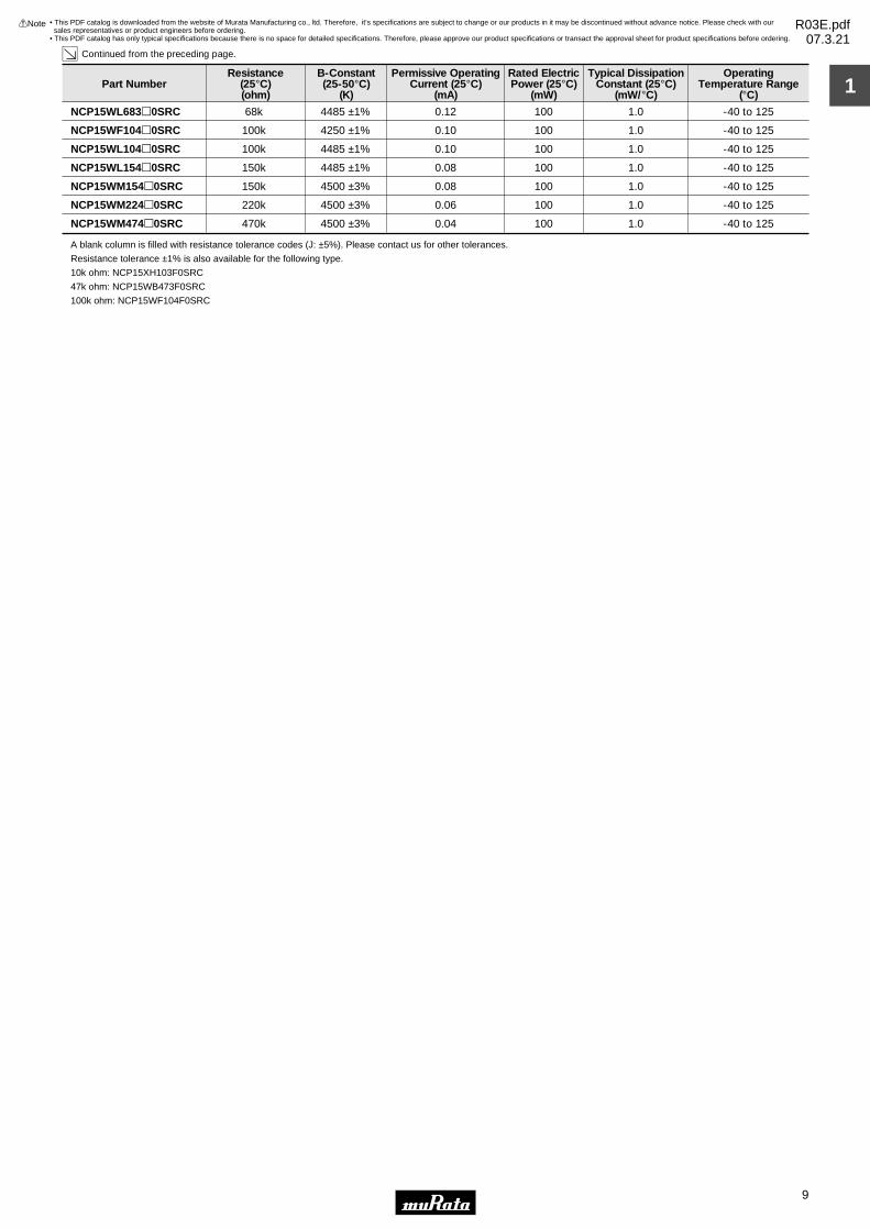
Part NumberResistance
(25°C)(ohm)
B-Constant(25-50°C)
(K)
Permissive OperatingCurrent (25°C)
(mA)
Rated ElectricPower (25°C)
(mW)
Typical DissipationConstant (25°C)
(mW/°C)
OperatingTemperature Range
(°C)
Continued from the preceding page.
NCP15WL683p0SRC 68k 4485 ±1% 0.12 100 1.0 -40 to 125
NCP15WF104p0SRC 100k 4250 ±1% 0.10 100 1.0 -40 to 125
NCP15WL104p0SRC 100k 4485 ±1% 0.10 100 1.0 -40 to 125
NCP15WL154p0SRC 150k 4485 ±1% 0.08 100 1.0 -40 to 125
NCP15WM154p0SRC 150k 4500 ±3% 0.08 100 1.0 -40 to 125
NCP15WM224p0SRC 220k 4500 ±3% 0.06 100 1.0 -40 to 125
NCP15WM474p0SRC 470k 4500 ±3% 0.04 100 1.0 -40 to 125
A blank column is filled with resistance tolerance codes (J: ±5%). Please contact us for other tolerances.
Resistance tolerance ±1% is also available for the following type.
10k ohm: NCP15XH103F0SRC
47k ohm: NCP15WB473F0SRC
100k ohm: NCP15WF104F0SRC
• This PDF catalog is downloaded from the website of Murata Manufacturing co., ltd. Therefore, it’s specifications are subject to change or our products in it may be discontinued without advance notice. Please check with our sales representatives or product engineers before ordering.
• This PDF catalog has only typical specifications because there is no space for detailed specifications. Therefore, please approve our product specifications or transact the approval sheet for product specifications before ordering.
!Note R03E.pdf07.3.21

10
2
!Note • Please read rating and !CAUTION (for storage, operating, rating, soldering, mounting and handling) in this catalog to prevent smoking and/or burning, etc.• This catalog has only typical specifications because there is no space for detailed specifications. Therefore, please approve our product specifications or transact the approval sheet for product specifications before ordering.
NTC/PTC Thermistors for AutomotiveNTC Thermistor Chip Type 0603 (1608) Size (Meet AEC-Q200rev.C)
0402/0603 sized Chip NTC Thermistors have Ni barrier termination and provide excellent solderability and offer high stability in environment by unique inner construction.
Features1. NCP18xx0S series can meet AEC-Q200rev.C requirements2. Excellent solderability and high stability in environment3. Excellent long time aging stability4. High accuracy in resistance and B-constant5. Flow/Reflow soldering possible6. Lead is not contained in the product7. NCP18 series are recognized by UL (UL1434, File No.E137188 Vol.2, Sec.2 ).
Applications1. Car audio, car navigation2. Various engine control units3. Circuits for ETC equipment4. Various motor driving circuits5. Temperature compensation for various circuits
Electrode(Ag System + Ni Plating + Sn Plating)
0.2—0.6 0.2—0.61.6±0.15
(in mm)
0.8±
0.15
0.8±
0.15
Part NumberResistance
(25°C)(ohm)
B-Constant(25-50°C)
(K)
Permissive OperatingCurrent (25°C)
(mA)
Rated ElectricPower (25°C)
(mW)
Typical DissipationConstant (25°C)
(mW/°C)
OperatingTemperature Range
(°C)
NCP18XF101p0SRB 100 3250 ±3% 3.10 100 1.0 -40 to 125
NCP18XF151p0SRB 150 3250 ±3% 2.50 100 1.0 -40 to 125
NCP18XM221p0SRB 220 3500 ±3% 2.10 100 1.0 -40 to 125
NCP18XM331p0SRB 330 3500 ±3% 1.70 100 1.0 -40 to 125
NCP18XQ471p0SRB 470 3650 ±2% 1.40 100 1.0 -40 to 125
NCP18XQ681p0SRB 680 3650 ±3% 1.20 100 1.0 -40 to 125
NCP18XQ102p0SRB 1.0k 3650 ±2% 1.00 100 1.0 -40 to 125
NCP18XW152p0SRB 1.5k 3950 ±3% 0.81 100 1.0 -40 to 125
NCP18XW222p0SRB 2.2k 3950 ±3% 0.67 100 1.0 -40 to 125
NCP18XW332p0SRB 3.3k 3950 ±3% 0.55 100 1.0 -40 to 125
NCP18XM472p0SRB 4.7k 3500 ±2% 0.46 100 1.0 -40 to 125
NCP18XW682p0SRB 6.8k 3950 ±3% 0.38 100 1.0 -40 to 125
NCP18XH103p0SRB 10k 3380 ±1% 0.31 100 1.0 -40 to 125
NCP18XW153p0SRB 15k 3950 ±3% 0.25 100 1.0 -40 to 125
NCP18XW223p0SRB 22k 3950 ±3% 0.21 100 1.0 -40 to 125
NCP18WB333p0SRB 33k 4050 ±3% 0.17 100 1.0 -40 to 125
NCP18WB473p1SRB 47k 4050 ±1.5% 0.14 100 1.0 -40 to 125
NCP18WB473p0SRB 47k 4050 ±2% 0.14 100 1.0 -40 to 125
NCP18WD683p0SRB 68k 4150 ±3% 0.12 100 1.0 -40 to 125
NCP18WF104p3SRB 100k 4200 ±1% 0.10 100 1.0 -40 to 125
NCP18WF104p0SRB 100k 4250 ±2% 0.10 100 1.0 -40 to 125
NCP18WM154p0SRB 150k 4500 ±3% 0.08 100 1.0 -40 to 125
NCP18WM224p0SRB 220k 4500 ±3% 0.06 100 1.0 -40 to 125
NCP18WM474p0SRB 470k 4500 ±3% 0.04 100 1.0 -40 to 125
A blank column is filled with resistance tolerance codes (J: ±5%). Please contact us for other tolerances.
Resistance tolerance ±1% is also available for the following type.
10k ohm: NCP18XH103F0SRB
47k ohm: NCP18WB473F1SRB
100k ohm: NCP18WF104F3SRB
• This PDF catalog is downloaded from the website of Murata Manufacturing co., ltd. Therefore, it’s specifications are subject to change or our products in it may be discontinued without advance notice. Please check with our sales representatives or product engineers before ordering.
• This PDF catalog has only typical specifications because there is no space for detailed specifications. Therefore, please approve our product specifications or transact the approval sheet for product specifications before ordering.
!Note R03E.pdf07.3.21

For NTC Thermistors Chip Type Standard Land Pattern Dimensions
11
2
!Note • Please read rating and !CAUTION (for storage, operating, rating, soldering, mounting and handling) in this catalog to prevent smoking and/or burning, etc.• This catalog has only typical specifications because there is no space for detailed specifications. Therefore, please approve our product specifications or transact the approval sheet for product specifications before ordering.
Chip
Land
Solder Resist
b a
c
(in mm)
Part NumberSolderingMethods c
NCP15 Reflow Soldering 0.5
NCP18Flow Soldering
Reflow Soldering
0.6-0.8
b
0.4-0.5
0.8-0.9
a
0.4
0.6-1.0
0.6-0.80.6-0.70.6-0.8
Chip (LgW)
Dimensions (mm)
1.0g0.5
1.6g0.8
• This PDF catalog is downloaded from the website of Murata Manufacturing co., ltd. Therefore, it’s specifications are subject to change or our products in it may be discontinued without advance notice. Please check with our sales representatives or product engineers before ordering.
• This PDF catalog has only typical specifications because there is no space for detailed specifications. Therefore, please approve our product specifications or transact the approval sheet for product specifications before ordering.
!Note R03E.pdf07.3.21

1
Continued on the following page.
355.823273.975213.003166.943131.997105.31884.67068.62855.98145.85937.81931.39626.21122.00018.56015.73513.40311.4629.8428.4887.3486.3995.5954.8964.2993.7953.3602.9832.6562.3672.1161.9011.7121.543
NCPppXC22022Ω
533.734410.962319.504250.415197.996157.978127.005102.94283.97268.78956.72847.09439.31733.00027.84023.60320.10417.19314.76312.73211.0229.5988.3927.3456.4485.6925.0404.4743.9833.5513.1732.8512.5682.314
NCPppXC33033Ω
760.166585.310455.051356.652281.994224.998180.886146.614119.59697.97280.79467.07355.99747.00039.65133.61628.63324.48721.02618.13315.69813.67011.95210.4619.1848.1077.1796.3735.6735.0574.5204.0603.6573.296
NCPppXC47047Ω
1099.815846.832658.372516.007407.991325.529261.707212.123173.033141.747116.89497.04281.01668.00057.36848.63641.42635.42830.42126.23522.71219.77817.29315.13413.28811.72910.3869.2208.2087.3176.5395.8745.2914.768
NCPppXC68068Ω
1824.1751390.6851070.653831.138650.960514.441409.700328.877265.759215.785176.395145.161120.152100.00083.66970.36159.45650.47043.02936.83031.64927.36423.75620.65118.01115.80013.90812.26310.8449.6228.5637.6486.8506.162
NCPppXF101100Ω
2736.2622086.0281605.9791246.708976.440771.661614.550493.315398.639323.677264.592217.742180.228150.000125.503105.54189.18475.70564.54355.24647.47341.04535.63430.97627.01623.70020.86218.39416.26514.43412.84411.47210.2759.243
NCPppXF151150Ω
4947.9043703.7552798.8732135.8871645.0371278.0341000.620789.612627.752502.474405.010328.480268.044220.000181.576150.668125.681105.33688.71775.05963.77754.41546.63140.11534.63730.01326.11022.79019.95717.54115.45313.66312.11410.778
NCPppXM221220Ω
7421.8565555.6324198.3093203.8312467.5551917.0511500.9301184.418941.628753.711607.514492.720402.066330.000272.365226.002188.521158.004133.076112.58895.66681.62269.94660.17251.95545.01939.16534.18629.93526.31223.18020.49418.17116.168
NCPppXM331330Ω
17104.85412685.2489505.8557193.2195493.4364229.5993283.6752568.4112024.1581606.2751283.6911032.245835.351680.000556.733458.287379.320315.504263.749221.579186.998158.499134.960115.38399.02985.35673.83964.14055.90548.88842.91837.79533.40929.618
NCPppXQ681680Ω
25.15418.65513.97910.5788.0796.2204.8293.7772.9772.3621.8881.5181.2291.0000.8190.6740.5580.4640.3880.3260.2750.2330.1990.1700.1460.1260.1090.0940.0820.0720.0630.0560.0490.044
NCPppXQ1021.0kΩ
51.79137.17227.00519.84314.72811.0448.3626.3894.9223.8252.9942.3611.8761.5001.2070.9780.7970.6530.5380.4460.3710.3110.2610.2210.1870.1600.1370.1170.1010.0880.0760.0670.0580.051
NCPppXW1521.5kΩ
11822.4738767.7456570.2244971.7843796.9332923.4002269.5991775.2251399.0501110.220887.257713.463577.375470.000384.800316.757262.177218.069182.297153.150129.249109.55193.28179.75068.44658.99651.03644.33238.64033.79029.66426.12323.09120.472
NCPppXQ471470Ω
3100K 3100K 3100K 3100K 3250K 3250K
3500K 3500K 3650K 3650K 3950K3650K
Resistance (Ω) Resistance (Ω) Resistance (Ω) Resistance (Ω) Resistance (Ω) Resistance (Ω)
Resistance (Ω) Resistance (Ω) Resistance (Ω) Resistance (kΩ) Resistance (kΩ)Resistance (Ω)
Detailed Resistance-Temperature Tables are downloadable from the following URL.
http://search.murata.co.jp/Ceramy/CatsearchAction.do?sLang=en
Y40Y35Y30Y25Y20Y15Y10Y505
101520253035404550556065707580859095
100105110115120125
Temp. (°C)B-ConstantResistance
Part Number
Y40Y35Y30Y25Y20Y15Y10Y505
101520253035404550556065707580859095
100105110115120125
Temp. (°C)B-ConstantResistance
Part Number
For NTC Thermistors Chip Type Temperature Characteristics (Center Value)
12
2
!Note • Please read rating and !CAUTION (for storage, operating, rating, soldering, mounting and handling) in this catalog to prevent smoking and/or burning, etc.• This catalog has only typical specifications because there is no space for detailed specifications. Therefore, please approve our product specifications or transact the approval sheet for product specifications before ordering.
• This PDF catalog is downloaded from the website of Murata Manufacturing co., ltd. Therefore, it’s specifications are subject to change or our products in it may be discontinued without advance notice. Please check with our sales representatives or product engineers before ordering.
• This PDF catalog has only typical specifications because there is no space for detailed specifications. Therefore, please approve our product specifications or transact the approval sheet for product specifications before ordering.
!Note R03E.pdf07.3.21

2
Continued from the preceding page.
Continued on the following page.
517.912371.724270.048198.426147.278110.43983.61763.88849.22138.24529.93623.61318.75615.00012.0749.7807.9696.5315.3824.4593.7133.1082.6132.2081.8731.5971.3671.1741.0130.8780.7630.6650.5820.511
NCPppXW15315kΩ
759.605545.196396.070291.025216.008161.977122.63893.70272.19156.09343.90734.63327.50922.00017.70914.34411.6889.5787.8946.5405.4464.5593.8323.2392.7482.3422.0041.7221.4861.2871.1190.9750.8540.750
NCPppXW22322kΩ
1073.436753.900535.073383.590277.643202.813149.462111.08283.23362.85847.83136.66428.30422.00017.21413.55710.7448.5666.8715.5434.4973.6693.0092.4812.0561.7131.4341.2061.0190.8660.7390.6330.5450.471
NCPppWL22322kΩ
1227.263874.449630.851460.457339.797253.363190.766144.964111.08785.84266.86152.47041.47133.00026.43021.29817.26614.07611.5389.5067.8706.5495.4754.5953.8743.2822.7892.3792.0381.7511.5091.3061.1340.987
NCPppWB33333kΩ
1610.1541130.850802.609575.385416.464304.219224.193166.623124.85094.28771.74754.99642.45533.00025.82220.33516.11512.84910.3068.3146.7465.5034.5133.7213.0842.5692.1511.8091.5291.2991.1080.9490.8170.707
NCPppWL33333kΩ
1747.9201245.428898.485655.802483.954360.850271.697206.463158.214122.25995.22774.73059.06547.00037.64330.33424.59120.04816.43313.53911.2099.3287.7986.5445.5184.6743.9723.3882.9022.4942.1501.8601.6151.406
NCPppWB47347kΩ
195.652148.171113.34787.55968.23753.65042.50633.89227.21922.02117.92614.67412.08110.0008.3156.9485.8344.9174.1613.5353.0142.5862.2281.9251.6691.4521.2681.1100.9740.8580.7580.6720.5960.531
NCPppXH10310kΩ
328.996237.387173.185127.77395.32771.74654.56441.81332.33025.19419.78515.65112.46810.0008.0726.5565.3564.4013.6353.0192.5212.1151.7811.5091.2841.0970.9410.8100.7010.6080.5300.4630.4060.358
NCPppXV10310kΩ
3950K 3950K 4485K 4050K 4485K 4050K
3380K 3900K
Resistance (kΩ) Resistance (kΩ) Resistance (kΩ) Resistance (kΩ) Resistance (kΩ) Resistance (kΩ)
Resistance (kΩ) Resistance (kΩ)
Detailed Resistance-Temperature Tables are downloadable from the following URL.
http://search.murata.co.jp/Ceramy/CatsearchAction.do?sLang=en
Y40Y35Y30Y25Y20Y15Y10Y505
101520253035404550556065707580859095
100105110115120125
Temp. (°C)B-ConstantResistance
Part Number
Y40Y35Y30Y25Y20Y15Y10Y505
101520253035404550556065707580859095
100105110115120125
Temp. (°C)B-ConstantResistance
Part Number
75.96154.52039.60729.10321.60116.19812.2649.3707.2195.6094.3913.4632.7512.2001.7711.4341.1690.9580.7890.6540.5450.4560.3830.3240.2750.2340.2000.1720.1490.1290.1120.0980.0850.075
NCPppXW2222.2kΩ
113.94181.77959.41143.65432.40124.29718.39614.05510.8298.4146.5865.1954.1263.3002.6562.1521.7531.4371.1840.9810.8170.6840.5750.4860.4120.3510.3010.2580.2230.1930.1680.1460.1280.113
NCPppXW3323.3kΩ
105.70579.12659.79445.63035.14427.30321.37716.86913.41110.7358.6537.0185.7264.7003.8793.2192.6852.2501.8951.6041.3631.1630.9960.8570.7400.6410.5580.4870.4260.3750.3300.2920.2590.230
NCPppXM4724.7kΩ
234.787168.515122.42289.95366.76650.06637.90628.96322.31317.33813.57110.7058.5036.8005.4744.4343.6132.9612.4402.0221.6831.4091.1851.0010.8490.7240.6200.5320.4590.3980.3460.3020.2640.232
NCPppXW6826.8kΩ
3950K 3950K 3500K 3950KResistance (kΩ) Resistance (kΩ) Resistance (kΩ) Resistance (kΩ)
For NTC Thermistors Chip Type Temperature Characteristics (Center Value)
13
2
!Note • Please read rating and !CAUTION (for storage, operating, rating, soldering, mounting and handling) in this catalog to prevent smoking and/or burning, etc.• This catalog has only typical specifications because there is no space for detailed specifications. Therefore, please approve our product specifications or transact the approval sheet for product specifications before ordering.
• This PDF catalog is downloaded from the website of Murata Manufacturing co., ltd. Therefore, it’s specifications are subject to change or our products in it may be discontinued without advance notice. Please check with our sales representatives or product engineers before ordering.
• This PDF catalog has only typical specifications because there is no space for detailed specifications. Therefore, please approve our product specifications or transact the approval sheet for product specifications before ordering.
!Note R03E.pdf07.3.21

3
Continued from the preceding page.
Y40Y35Y30Y25Y20Y15Y10Y505
101520253035404550556065707580859095
100105110115120125
Temp. (°C)B-ConstantResistance
Part Number
4879.2543426.8182432.1491743.5901262.012921.875679.373504.919378.333285.717217.414166.654128.653100.00078.24761.62248.83538.93731.23125.19520.44116.67513.67711.2779.3467.7856.5175.4824.6343.9353.3572.8772.4762.141
NCPppWL104100kΩ
7318.8815140.2283648.2242615.3851893.0181382.8131019.059757.379567.499428.575326.121249.981192.979150.000117.37092.43373.25258.40646.84637.79330.66125.01320.51616.91614.01911.6789.7768.2236.9515.9025.0354.3153.7143.211
NCPppWL154150kΩ
7899.4665466.1183834.4992720.5231951.2161415.5651036.984767.079572.667431.264327.405250.538193.166150.000117.28192.29373.09058.24046.66537.60530.45324.80420.29316.67913.77611.4289.5207.9666.6885.6394.7724.0523.4542.955
NCPppWM154150kΩ
11585.8848016.9735623.9313990.1002861.7842076.1621520.9091125.049839.912632.521480.194367.455283.310220.000172.012135.364107.19885.41968.44155.15344.66536.37929.76324.46220.20516.76113.96211.6849.8098.2706.9985.9425.0674.334
NCPppWM224220kΩ
24751.66117127.16912014.7628524.3056113.8114435.4373249.2162403.5151794.3581351.2941025.870785.018605.252470.000367.480289.186229.014182.485146.215117.82895.42077.71863.58452.26043.16635.80829.82824.96120.95517.66814.95112.69510.8249.259
NCPppWM474470kΩ
4485K 4485K
4500K 4485K 4500K
Resistance (kΩ) Resistance (kΩ)
Resistance (kΩ) Resistance (kΩ) Resistance (kΩ)
Y40Y35Y30Y25Y20Y15Y10Y505
101520253035404550556065707580859095
100105110115120125
Temp. (°C)B-ConstantResistance
Part Number
2293.2491610.6051143.110819.487593.146433.281319.305237.312177.816134.287102.18478.32760.46747.00036.77628.96222.95218.30114.67911.8429.6077.8376.4285.3004.3933.6593.0632.5772.1781.8491.5781.3521.1641.006
NCPppWL47347kΩ
3317.8932330.2371653.8621185.641858.168626.875461.974343.345257.266194.287147.841113.32587.48468.00053.20841.90333.20826.47721.23717.13313.90011.3399.3007.6686.3565.2944.4323.7283.1512.6762.2831.9561.6841.456
NCPppWL68368kΩ
4397.1193088.5992197.2251581.8811151.037846.579628.988471.632357.012272.500209.710162.651127.080100.00079.22263.16750.67740.90433.19527.09122.22418.32315.18412.63510.5668.8737.4816.3375.3844.5943.9343.3802.9162.522
NCPppWF104100kΩ
2735.3591937.3911389.3451008.014738.978547.456409.600309.217235.606180.980140.139109.34485.92968.00054.16743.42135.01628.40623.16618.99715.65712.96710.7949.0217.5756.3875.4074.5983.9223.3592.8872.4892.1551.870
NCPppWD68368kΩ
4485K 4485K 4250K ∗4150KResistance (kΩ) Resistance (kΩ) Resistance (kΩ)Resistance (kΩ)
∗ B-Constant of NCP18WF104F1SRB is 4200K. Please contact us for the detail data.Detailed Resistance - Temperature Tables are downloadable from the following URL.
http://search.murata.co.jp/Ceramy/CatsearchAction.do?sLang=en
For NTC Thermistors Chip Type Temperature Characteristics (Center Value)
14
2
!Note • Please read rating and !CAUTION (for storage, operating, rating, soldering, mounting and handling) in this catalog to prevent smoking and/or burning, etc.• This catalog has only typical specifications because there is no space for detailed specifications. Therefore, please approve our product specifications or transact the approval sheet for product specifications before ordering.
• This PDF catalog is downloaded from the website of Murata Manufacturing co., ltd. Therefore, it’s specifications are subject to change or our products in it may be discontinued without advance notice. Please check with our sales representatives or product engineers before ordering.
• This PDF catalog has only typical specifications because there is no space for detailed specifications. Therefore, please approve our product specifications or transact the approval sheet for product specifications before ordering.
!Note R03E.pdf07.3.21

No. AEC-Q200 Test Item Specifications AEC-Q200 Test Methods
-Pre-and Post-StressElectrical Test
1
(*1)•Resistance(R25) change should be less than ±5%.•B-constant(B25/50) change should be less than ±2%.•No visible damage.
High TemperatureExposure(Storage)
2125±3 °C in air for 1000 hours.Measurement at 24±2 hours after test condition.
•Resistance(R25) change should be less than ±5%.•B-constant(B25/50) change should be less than ±2%.•No visible damage.
TemperatureCycling
3
Perform the 1000 cycles according to the four heat treatments listed in the following table.
Measurement at 24±2 hours after test condition.
•Resistance(R25) change should be less than ±5%.•B-constant(B25/50) change should be less than ±2%.•No visible damage.
MoistureResistance
4
Apply the 24 hours heat (25 to 65 °C) and humidity (80 to 98%)treatment shown below, 10 consecutive times.
Measurement at 24±2 hours after test condition.
(*2)•Resistance(R25) change should be less than ±10%.•B-constant(B25/50) change should be less than ±2%.•No visible damage.
Biased Humidity585±2 °C, 85%RH in air for 1000 hours with Permissive Operating Current.Measurement at 24±2 hours after test condition.
•Resistance(R25) change should be less than ±5%.•B-constant(B25/50) change should be less than ±2%.•No visible damage.
Operational Life6125±3 °C in air for 1000 hours with Permissive Operating Current.Measurement at 24±2 hours after test condition.
No defects of abnormalities.External Visual7 Visual Inspection.
Within the specified dimensions.PhysicalDimension
8 Using calipers
N/ATerminal Strengh(Leaded)
9
•Resistance(R25) change should be less than ±5%.•B-constant(B25/50) change should be less than ±2%.•No visible damage.
Resistance to Solvents
10Per MIL-STD-202 Method 215Solvent 1: 1 part (by volume) of isopropyl alcohol
3 part (by volume) of mineral spirits.
•Resistance(R25) change should be less than ±5%.•B-constant(B25/50) change should be less than ±2%.•No visible damage.
Mechanical Shock11Per MIL-STD-202 Method 213 Test Condition F1500g's, 0.5ms, In 3 directions perpendicularly intersectingeach other (total 18 times).
(*1)•Resistance(R25) change should be less than ±5%.•B-constant(B25/50) change should be less than ±2%.•No visible damage.
Vibration12
Simple harmonic motion between 10Hz to 2.0k Hz and back to10 Hz of max. amplitude 1.5mm for 20 minutes. This motionshould be applied for 12 times in each of 3 mutuallyperpendicular directions (total of 36 times).
(*1)•Resistance(R25) change should be less than ±5%.•B-constant(B25/50) change should be less than ±2%.•No visible damage.
Resistance to Soldering Heat
13Per MIL-STD-202 Method 210Test Condition B, 260 °C for 10 +/-1 seconds
• The Test Condition specification (*1,*2) is applied to the follow P/N.P/N: NCP15XH103**SR*, NCP15WL233**SR*, NCP15WL333**SR*, NCP15WL473**SR*, NCP15WL683**SR*, NCP15WL104**SR*,
NCP15WL154**SR*, NCP15WB473**SR*, NCP15WF104**SR*, NCP18XH103**SR*,(*1) Resistance(R25) change should be less than 1%
B-constant(B25/50) change should be less than 1%(*2) Resisitance(R25) change should be less than 5%
B-constant(B25/50) change should be less than 1%
StepTemp. (deg.C)
Time (min.)-55+0/-3
15±3Room Temp.
1125+3/-0
15±3Room Temp.
1
1 2 3 4
Humidity90 to 98%
Humidity80 to 98%
Humidity90 to 98%
Humidity80 to 98%
Humidity90 to 98%
One cycle 24 hoursT
empe
ratu
re(d
eg.C
)Hours
05
10152025303540455055606570
0 1 2 3 4 5 6 7 8 9 10 11 12 13 14 15 16 17 18 19 20 21 22 23 24
Initial measurement
+10deg.C
-2
Continued on the following page.
For NTC Thermistors Chip Type Specifications and Test Methods
15
2
!Note • Please read rating and !CAUTION (for storage, operating, rating, soldering, mounting and handling) in this catalog to prevent smoking and/or burning, etc.• This catalog has only typical specifications because there is no space for detailed specifications. Therefore, please approve our product specifications or transact the approval sheet for product specifications before ordering.
• This PDF catalog is downloaded from the website of Murata Manufacturing co., ltd. Therefore, it’s specifications are subject to change or our products in it may be discontinued without advance notice. Please check with our sales representatives or product engineers before ordering.
• This PDF catalog has only typical specifications because there is no space for detailed specifications. Therefore, please approve our product specifications or transact the approval sheet for product specifications before ordering.
!Note R03E.pdf07.3.21

No. AEC-Q200 Test Item Specifications AEC-Q200 Test Methods
•Resistance(R25) change should be less than ±5%.•B-constant(B25/50) change should be less than ±2%.•No visible damage.
Thermal Shock14
Perform the 300 cycles according to the two heat treatmentslisted in the following table. (Maximum transfer time is 20seconds.)
Measurement at 24±2 hours after test condition.
•Resistance(R25) change should be less than ±5%.•B-constant(B25/50) change should be less than ±2%.•No visible damage.
ESD15 Per AEC-Q200-004
Minimum 95% of the whole electrode surface should be covered with solder.
Solderability16Per J-STD-002SMD b) Method B @ 215 °C category 3.
Within the specified tolerance.Electrical Characterization
17Resistance at 25 °C. B-constant (B25-50)
N/AFlammability18
(*1)•Resistance(R25) change should be less than ±5%.•B-constant(B25/50) change should be less than ±2%.•No visible damage.
Board Flex19
Per AEC-Q200-005Bend the board 2.0mm for 60 seconds.Use the follow land size.
(*1)•Resistance(R25) change should be less than ±5%.•B-constant(B25/50) change should be less than ±2%.•No visible damage.
Terminal Strengh (SMD)
20
Per AEC-Q200-006Apply an *18N force to the side of device for 60 seconds.Use follow land size.*5N (NCP15****0SRC)
• The Test Condition specification (*1,*2) is applied to the follow P/N.P/N: NCP15XH103**SR*, NCP15WL233**SR*, NCP15WL333**SR*, NCP15WL473**SR*, NCP15WL683**SR*, NCP15WL104**SR*,
NCP15WL154**SR*, NCP15WB473**SR*, NCP15WF104**SR*, NCP18XH103**SR*,(*1) Resistance(R25) change should be less than 1%
B-constant(B25/50) change should be less than 1%(*2) Resisitance(R25) change should be less than 5%
B-constant(B25/50) change should be less than 1%
Continued from the preceding page.
StepTemp. (°C)Time (min.)
-55+0/-315±3
125+3/-015±3
1 2
TypeNCP15****0SRCNCP18****0SRB
0.40.6
1.21.8
0.50.6
(in mm)
a b c
ac
b
TypeNCP15****0SRCNCP18****0SRB
0.41.0
1.53.0
0.51.2
(in mm)
a b c
ac
b
For NTC Thermistors Chip Type Specifications and Test Methods
16
2
!Note • Please read rating and !CAUTION (for storage, operating, rating, soldering, mounting and handling) in this catalog to prevent smoking and/or burning, etc.• This catalog has only typical specifications because there is no space for detailed specifications. Therefore, please approve our product specifications or transact the approval sheet for product specifications before ordering.
• This PDF catalog is downloaded from the website of Murata Manufacturing co., ltd. Therefore, it’s specifications are subject to change or our products in it may be discontinued without advance notice. Please check with our sales representatives or product engineers before ordering.
• This PDF catalog has only typical specifications because there is no space for detailed specifications. Therefore, please approve our product specifications or transact the approval sheet for product specifications before ordering.
!Note R03E.pdf07.3.21

For NTC Thermistors Chip Type !Caution/Notice
17
2
!Note • Please read rating and !CAUTION (for storage, operating, rating, soldering, mounting and handling) in this catalog to prevent smoking and/or burning, etc.• This catalog has only typical specifications because there is no space for detailed specifications. Therefore, please approve our product specifications or transact the approval sheet for product specifications before ordering.
!Caution (Storage and Operating Condition)This product is designed for application in an ordinary environment (normal room temperature, humidity and atmospheric pressure). Do not use under the following conditions because all these factors can deteriorate the product characteristics or cause failures and burn-out.1. Corrosive gas or deoxidizing gas (Chlorine gas, Hydrogen sulfide gas, Ammonia gas, Sulfuric acid gas, Nitric oxide gas, etc.)
2. Volatile or flammable gas3. Dusty conditions4. Under vacuum, or under high or low-pressure5. Wet or humid locations6. Places with salt water, oils, chemical liquids or organic solvents7. Strong vibrations8. Other places where similar hazardous conditions exist
!Caution (Other)Be sure to provide an appropriate fail-safe function on your product to prevent secondary damages that may be caused by the abnormal function or the failure of our product.
Notice (Storage and Operating Condition)To keep solderability of product from declining, thefollowing storage condition is recommended.1. Storage condition: Temperature -10 to +40 degrees C Humidity less than 75%RH (not dewing condition)2. Storage term: Use this product within 6 months after delivery by first-in and first-out stocking system.
3. Handling after unpacking: After unpacking, reseal product promptly or store it in a sealed container with a drying agent.4. Storage place: Do not store this product in corrosive gas (Sulfuric acid gas, Chlorine gas, etc.) or in direct sunlight.
Notice (Rating)Use this product within the specified temperature range.Higher temperature may cause deterioration of the characteristics or the material quality of this product.
• This PDF catalog is downloaded from the website of Murata Manufacturing co., ltd. Therefore, it’s specifications are subject to change or our products in it may be discontinued without advance notice. Please check with our sales representatives or product engineers before ordering.
• This PDF catalog has only typical specifications because there is no space for detailed specifications. Therefore, please approve our product specifications or transact the approval sheet for product specifications before ordering.
!Note R03E.pdf07.3.21
1
Allowable Reflow Soldering Temperature and Time Standard Soldering Conditions
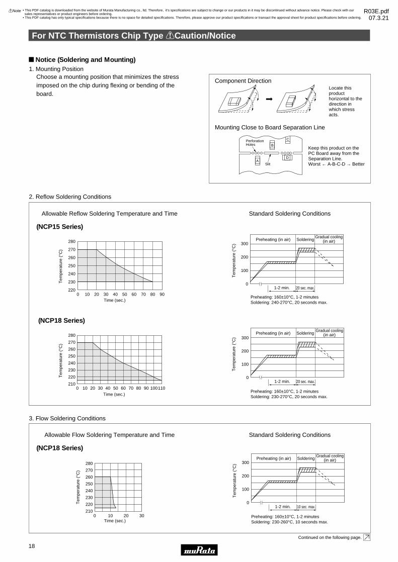
Locate this product horizontal to the direction in which stress acts.
Keep this product on the PC Board away from the Separation Line. Worst ← A-B-C-D → Better
Component Direction
Mounting Close to Board Separation Line
A
B
D
CPerforationHoles
Slit
1. Mounting Position
2. Reflow Soldering Conditions
Choose a mounting position that minimizes the stress imposed on the chip during flexing or bending of the board.
Continued on the following page.
Time (sec.)
Tem
pera
ture
(°C
)
280
270
260
250
240
230
220
2100 1109020 30 40 50 60 70 1008010
Tem
pera
ture
(°C
)
Preheating (in air) SolderingGradual cooling
(in air)300
200
100
01-2 min. 20 sec. max.
Preheating: 160±10°C, 1-2 minutesSoldering: 230-270°C, 20 seconds max.
Time (sec.)
Tem
pera
ture
(°C
)
280
270
260
250
240
230
2200 9020 30 40 50 60 70 8010
Tem
pera
ture
(°C
)Preheating (in air) Soldering
Gradual cooling(in air)300
200
100
01-2 min. 20 sec. max.
Preheating: 160±10°C, 1-2 minutesSoldering: 240-270°C, 20 seconds max.
(NCP18 Series)
(NCP15 Series)
Time (sec.)
Tem
pera
ture
(°C
)
Tem
pera
ture
(°C
)280
270
260
250
240
230
220
2100 10 20 30
Preheating (in air) SolderingGradual cooling
(in air)300
200
100
01-2 min. 10 sec. max.
Preheating: 160±10°C, 1-2 minutesSoldering: 230-260°C, 10 seconds max.
3. Flow Soldering Conditions
(NCP18 Series)
Allowable Flow Soldering Temperature and Time Standard Soldering Conditions
Notice (Soldering and Mounting)
For NTC Thermistors Chip Type !Caution/Notice
18
2
!Note • Please read rating and !CAUTION (for storage, operating, rating, soldering, mounting and handling) in this catalog to prevent smoking and/or burning, etc.• This catalog has only typical specifications because there is no space for detailed specifications. Therefore, please approve our product specifications or transact the approval sheet for product specifications before ordering.
• This PDF catalog is downloaded from the website of Murata Manufacturing co., ltd. Therefore, it’s specifications are subject to change or our products in it may be discontinued without advance notice. Please check with our sales representatives or product engineers before ordering.
• This PDF catalog has only typical specifications because there is no space for detailed specifications. Therefore, please approve our product specifications or transact the approval sheet for product specifications before ordering.
!Note R03E.pdf07.3.21

2
For removing the flux after soldering, observe the following points in order to avoid deterioration of the characteristics or any change of the external electrodes' quality.
(1) Solder and Paste(a) Reflow Soldering: NCP15/NCP18 Series
Use RA/RMA type or equivalent type of solder paste. For your reference, we are using the solder paste below for any internal tests of this product.•RMA9086 90-4-M20 (Sn:Pb=63wt%:37wt%)(Manufactured by Alpha Metals Japan Ltd.)•M705-221BM5-42-11 (Sn:Ag:Cu=96.5wt%:3.0wt%:0.5wt%)(Manufactured by Senju Metal Industry Co., Ltd.)
(b) Flow Soldering: NCP18 SeriesWe are using the solder paste below for any internal tests of this product.•Sn:Pb=63wt%:37wt%•Sn:Ag:Cu=96.5wt%:3.0wt%:0.5wt%
(2) FluxUse Rosin-based flux.Do not use strong acidic flux (with halide content exceeding 0.2wt%)
NCP15 NCP18
Continued from the preceding page.
4. Solder and Flux
5. Cleaning Conditions
After cleaning, promptly dry this product.6. Drying
Isopropyl Alcohol
Less than 5 minutes at
room temp. or less than
2 minutes at 40°C max.
Less than 5 minutes
20W/r Frequency of 28
to 40kHz.
Isopropyl Alcohol
Less than 5 minutes at
room temp. or less than
2 minutes at 40°C max.
Less than 1 minute
20W/r Frequency of
several 10 to 100kHz.
Solvent
Dipping Cleaning
Ultrasonic Cleaning
Thin or insufficient adhesive may result in loose component contact with land during flow soldering.Low viscosity adhesive causes chips to slip after mounting.
NCP15
NCP18
100µm
150µm
1/3EVTVE
0.2mmVTVE
Part Number The Solder Paste Thickness T
Reference: Optimum Solder Amount
TE
Electrode
Solder Solder
The amount of solder is critical. Standard height of fillet is shown in the table below.Too much soldering may cause mechanical stress, resulting in cracking, mechanical and/or electronic damage.
8. Adhesive Application and Curing
7. Printing Conditions of Solder Paste
For NTC Thermistors Chip Type !Caution/Notice
19
2
!Note • Please read rating and !CAUTION (for storage, operating, rating, soldering, mounting and handling) in this catalog to prevent smoking and/or burning, etc.• This catalog has only typical specifications because there is no space for detailed specifications. Therefore, please approve our product specifications or transact the approval sheet for product specifications before ordering.
Notice (Handling)The ceramic of this product is fragile, and care mustbe taken to not load an excessive press-force, or to notgive a shock at handling. Such forces may cause cracking or chipping.
• This PDF catalog is downloaded from the website of Murata Manufacturing co., ltd. Therefore, it’s specifications are subject to change or our products in it may be discontinued without advance notice. Please check with our sales representatives or product engineers before ordering.
• This PDF catalog has only typical specifications because there is no space for detailed specifications. Therefore, please approve our product specifications or transact the approval sheet for product specifications before ordering.
!Note R03E.pdf07.3.21

20
3
!Note • Please read rating and !CAUTION (for storage, operating, rating, soldering, mounting and handling) in this catalog to prevent smoking and/or burning, etc.• This catalog has only typical specifications because there is no space for detailed specifications. Therefore, please approve our product specifications or transact the approval sheet for product specifications before ordering.
NTC/PTC Thermistors for AutomotiveNTC Thermistor Lead Type for Temperature Sensor
Solder Plated Copper Ply Wireø0.4±0.03
31±1
2.5±1.0
6.0
max
.
3.0 max. (*3.3 max.) 1.8 max. (*2.5 max.)
Epoxy Resin
(in mm)
* It applies to NTSS0XM202, NTSS0WB203 and NTSS0WC303 Type.
Temperature Tolerance - Temperature CharacteristicsResistance tolerance:1% B - Constant tolerance:1%
Temperature (°C)
Tem
pera
ture
Tol
eran
ce (
±°C
)
0
1.0
2.0
3.0
-50 0 50 100 150
Resistance tolerance:1% B - Constant tolerance:0.5%
Temperature (°C)
Tem
pera
ture
Tol
eran
ce (
±°C
)
0
1.0
2.0
3.0
-50 0 50 100 150
This product is a sensor type NTC Thermistor to be useful in the normal temperature range developed by the unique ceramic technology and the automatic assembly.
Features1. High-accuracy of B-Constant tolerance:+/-0.5% +/-1% of resistance and +/-0.5% of B-Constant is realized due to technical advantages of the material and manufacturing process.2. Quick response This product provides faster response time due to its smaller size.3. Taping type is available.4. Strong lead strength Original lead-wiring technique assures reliable connection. It can be formed and bent flexibly according to the mounting condition.
Applications1. Car audio, car navigation2. Various engine control units3. Circuits for ETC equipment4. Various motor driving circuits5. Temperature compensation for various circuits
Part NumberResistance
(25°C)(k ohm)
B-Constant(25-50°C)
(K)
Permissive OperatingCurrent (25°C)
(mA)
Rated ElectricPower (25°C)
(mW)
Typical DissipationConstant (25°C)
(mW/°C)
Thermal TimeConstant(25°C)(s)
OperatingTemperature Range
(°C)
NTSS0XM202pE1B0 2.0 3500 ±0.5% 1.05 21 2.1 7 -40 to 125
NTSS0XR502pE1B0 5.0 3700 ±1% 0.68 15 1.5 7 -40 to 125
NTSS0XH103pE1B0 10 3380 ±0.5% 0.38 15 1.5 7 -40 to 125
NTSS0XV103pE1B0 10 3900 ±0.5% 0.46 15 1.5 7 -40 to 125
NTSS0WB203pE1B0 20 4050 ±1% 0.31 21 2.1 7 -40 to 125
NTSS0WC303pE1B0 30 4100 ±1% 0.26 21 2.1 7 -40 to 125
NTSS0WD503pE1B0 50 4150 ±1% 0.20 15 1.5 7 -40 to 125
NTSS0WF104pE1B0 100 4250 ±1% 0.14 15 1.5 7 -40 to 125
A blank column is filled with resistance tolerance codes (F: ±1%, E: ±3%).
Taping type of part numbers with "N6A0" is available (Lead spacing=5mm).
• This PDF catalog is downloaded from the website of Murata Manufacturing co., ltd. Therefore, it’s specifications are subject to change or our products in it may be discontinued without advance notice. Please check with our sales representatives or product engineers before ordering.
• This PDF catalog has only typical specifications because there is no space for detailed specifications. Therefore, please approve our product specifications or transact the approval sheet for product specifications before ordering.
!Note R03E.pdf07.3.21

Y40Y35Y30Y25Y20Y15Y10Y505
101520253035404550556065707580859095100105110115120125
44.65733.50525.38819.40214.96111.6449.1337.1985.7164.5713.6822.9872.4372.0001.6511.3711.1430.9580.8070.6830.5820.4970.4260.3670.3180.2760.2400.2100.1830.1610.1420.1250.1110.099
123.48492.29569.61452.86040.48031.27524.33919.15415.14811.9649.5207.6246.1605.0004.0823.3542.7732.2991.9141.6071.3561.1490.9780.8340.7140.6120.5270.4560.3960.3450.3020.2640.2320.205
195.652148.171113.34787.55968.23753.65042.50633.89227.21922.02117.92614.67412.08110.0008.3156.9485.8344.9174.1613.5353.0142.5862.2281.9251.6691.4521.2681.1100.9740.8580.7580.6710.5960.531
347.808248.591179.973131.83297.67973.11955.30142.25732.58225.32419.84715.67912.47810.0008.0686.5525.3534.3993.6353.0202.5212.1151.7831.5101.2841.0960.9390.8080.6980.6050.5270.4600.4030.354
NTSppXM202 NTSppXR502 NTSppXH103 NTSppXV103
Resistance (kΩ) Resistance (kΩ) Resistance (kΩ) Resistance (kΩ)
1
733.007524.831380.184277.845205.260153.642116.01688.12567.52252.16840.61731.84725.15120.00016.01412.90210.4578.5276.9935.7714.7893.9923.3432.8092.3762.0201.7241.4761.2641.0850.9350.8120.7080.617
1149.500819.651591.391430.529316.870236.337177.842134.630102.81679.18361.46048.04537.83430.00023.95519.24915.56012.65710.3548.5257.0585.8694.9054.1133.4722.9452.5092.1431.8321.5711.3501.1711.0190.886
1948.5751387.289999.456728.895537.039399.167299.469226.186172.393132.857103.08980.43063.20150.00039.82531.91825.73320.87717.03413.92911.4399.4857.9066.6145.5584.6863.9673.3732.8782.4652.1181.8281.5831.374
4256.7523005.8882148.5141555.0201137.312839.314625.338469.127355.224272.045209.803162.713127.117100.00079.21563.15050.64940.88533.19527.01422.07918.22615.1242.598
10.5428.8527.4636.3215.3744.5853.9253.3762.9132.520
NTSppWB203 NTSppWC303 NTSppWD503 NTSppWF104
Resistance (kΩ) Resistance (kΩ) Resistance (kΩ) Resistance (kΩ)3500K 3700K 3380K 3900K 4050K 4100K 4150K 4250K2.0kΩ 5.0kΩ 10kΩ 10kΩ 20kΩ 30kΩ 50kΩ 100kΩ
Temp. (°C)B-ConstantResistance
Part Number
Detailed Resistance-Temperature Tables are downloadable from the following URL.
http://search.murata.co.jp/Ceramy/CatsearchAction.do?sLang=en
For NTC Thermistors Lead Type Temperature Characteristics (Center Value)
21
3
!Note • Please read rating and !CAUTION (for storage, operating, rating, soldering, mounting and handling) in this catalog to prevent smoking and/or burning, etc.• This catalog has only typical specifications because there is no space for detailed specifications. Therefore, please approve our product specifications or transact the approval sheet for product specifications before ordering.
• This PDF catalog is downloaded from the website of Murata Manufacturing co., ltd. Therefore, it’s specifications are subject to change or our products in it may be discontinued without advance notice. Please check with our sales representatives or product engineers before ordering.
• This PDF catalog has only typical specifications because there is no space for detailed specifications. Therefore, please approve our product specifications or transact the approval sheet for product specifications before ordering.
!Note R03E.pdf07.3.21
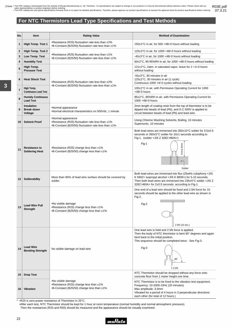
No. Item Rating Value Method of Examination
•Resistance (R25) fluctuation rate less than ±1%•B-Constant (B25/50) fluctuation rate less than ±1%
•Resistance (R25) fluctuation rate less than ±2%•B-Constant (B25/50) fluctuation rate less than ±1%
•Normal appearance•Normal electrical characteristics on 500Vdc, 1 minute
•No visible damage•Resistance (R25) change less than ±1%•B-Constant (B25/50) change less than ±1%
No visible damage on lead wire
•No visible damage•Resistance (R25) change less than ±1%•B-Constant (B25/50) change less than ±1%
•Resistance (R25) change less than ±1%•B-Constant (B25/50) change less than ±1%
•Resistance (R25) fluctuation rate less than ±2%•B-Constant (B25/50) fluctuation rate less than ±1%
High Temp. Test 1
High Temp. Test 2
Low Temp. Test
Humidity Test
High Temp. Pressure Test
Heat Shock Test
High Temp.Continuous Load Test
Humidy ContinuousLoad Test
Insulation Break-downVoltage
1
2
3
4
5
6
7
8
9
More than 90% of lead wire surface should be covered by solder.
Resistance toSoldering Heat
Solderability
11
12
Lead Wire PullStrength
Lead WireBending Strength
13
14
Drop Test
Vibration
15
16
121±2°C, 2atm. in saturated vapor, leave for 2 +1/-0 hourswithout loading
100±2°C in air, with Permissive Operating Current for 1000+48/-0 hours
85±2°C, 85%RH in air, with Permissive Operating Current for1000 +48/-0 hours
2mm length of coating resin from the top of thermistor is to bedipped into beads of lead (Pb), and D.C 500V is applied to circuit between beads of lead (Pb) and lead wire.
-55±3°C, 30 minutes in air125±2°C, 30 minutes in air (1 cycle)Continuous 1000 +4/-0 cycles without loading
125±3°C in air, for 1000 +48/-0 hours without loading
-40±3°C in air, for 1000 +48/-0 hours without loading
60±2°C, 90-95%RH in air, for 1000 +48/-0 hours without loading
150±2°C in air, for 500 +48/-0 hours without loading
•Normal appearance•Resistance (R25) fluctuation rate less than ±1%•B-Constant (B25/50) fluctuation rate less than ±1%
Solvent Proof10Using Chlorine Washing Solvents, Boiling, 10 minutesSupersonic, 10 minutes
Both lead wires are immersed into 350±10°C solder for 3.5±0.5seconds or 260±5°C solder for 10±1 seconds according to Fig-1. (solder <JIS Z 3282 H60A>)
Both lead wires are immersed into flux (25wt% colophony <JISK 5902> isopropyl alcohol <JIS K 8839>) for 5-10 seconds.Then both lead wires are immersed into 235±5°C solder <JIS Z3282 H60A> for 2±0.5 seconds. according to Fig-1.
One end of a lead wire should be fixed and 2.5N force for 10seconds should be applied to the other lead wire as shown inFig-2.
One lead wire is held and 2.5N force is applied. Then the body of NTC thermistor is bent 90° degrees and againbent back to the initial position. This sequence should be completed twice. See Fig-3.
NTC Thermistor should be dropped without any force onto concrete floor from 1 meter height one time.
NTC Thermistor is to be fixed to the vibration test equipment.Frequency: 10-2000-10Hz (20 minutes)Max amplitude: 3.0mmVibrated for a period of 4 hours in 3 perpendicular directionseach other (for total of 12 hours.)
6.0±
1.0m
m
Solder
Fig-1
2.5N (10 sec.)
Fig-2
2.5N
90˚
Fig-3
∗ •R25 is zero-power resistance of Thermistor in 25°C.•After each test, NTC Thermistor should be kept for 1 hour at room temperature (normal humidity and normal atmospheric pressure). Then the resistances (R25 and R50) should be measured and the appearance should be visually examined.
For NTC Thermistors Lead Type Specifications and Test Methods
22
3
!Note • Please read rating and !CAUTION (for storage, operating, rating, soldering, mounting and handling) in this catalog to prevent smoking and/or burning, etc.• This catalog has only typical specifications because there is no space for detailed specifications. Therefore, please approve our product specifications or transact the approval sheet for product specifications before ordering.
• This PDF catalog is downloaded from the website of Murata Manufacturing co., ltd. Therefore, it’s specifications are subject to change or our products in it may be discontinued without advance notice. Please check with our sales representatives or product engineers before ordering.
• This PDF catalog has only typical specifications because there is no space for detailed specifications. Therefore, please approve our product specifications or transact the approval sheet for product specifications before ordering.
!Note R03E.pdf07.3.21

For NTC Thermistors Lead Type !Caution/Notice
23
3
!Note • Please read rating and !CAUTION (for storage, operating, rating, soldering, mounting and handling) in this catalog to prevent smoking and/or burning, etc.• This catalog has only typical specifications because there is no space for detailed specifications. Therefore, please approve our product specifications or transact the approval sheet for product specifications before ordering.
!Caution (Storage and Operating Condition)This product is designed for application in an ordinary environment (normal room temperature, humidity and atmospheric pressure). Do not use under the following conditions because all these factors can deteriorate the product characteristics or cause failures and burn-out.1. Corrosive gas or deoxidizing gas (Chlorine gas, Hydrogen sulfide gas, Ammonia gas, Sulfuric acid gas, Nitric oxide gas, etc.)
2. Volatile or flammable gas3. Dusty conditions4. Under vacuum, or under high or low-pressure5. Wet or humid locations6. Places with salt water, oils, chemical liquids or organic solvents7. Strong vibrations8. Other places where similar hazardous conditions exist
!Caution (Other)Be sure to provide an appropriate fail-safe function on your product to prevent secondary damages that may be caused by the abnormal function or the failure of our product.
Notice (Storage and Operating Condition)To keep solderability of product from declining, thefollowing storage condition is recommended.1. Storage condition: Temperature -10 to +40 degrees C Humidity less than 75%RH (not dewing condition)2. Storage term: Use this product within 6 months after delivery by first-in and first-out stocking system.
3. Handling after unpacking: After unpacking, reseal product promptly or store it in a sealed container with a drying agent.4. Storage place: Do not store this product in corrosive gas (Sulfuric acid gas, Chlorine gas, etc.) or in direct sunlight.
Notice (Rating)Use this product within the specified temperature range.Higher temperature may cause deterioration of the characteristics or the material quality of this product.
Notice (Soldering and Mounting)1. Be sure that the preheat-up does not melt the soldering of this product. Excessive heat may cause failure to open, short or insulation break down.2. Do not touch the body with soldering iron. The soldering point should be min. 5mm away from the root of lead wire.
Notice (Handling)1. The ceramic element of this product is fragile, and care must be taken not to load an excessive press-force or not to give a shock at handling. Such forces may cause cracking or chipping.2. Do not apply an excessive force to the lead. Otherwise, it may cause junction between lead and element to break or crack. Holding element by side lead wire is recommended when lead wire is bent or cut.
• This PDF catalog is downloaded from the website of Murata Manufacturing co., ltd. Therefore, it’s specifications are subject to change or our products in it may be discontinued without advance notice. Please check with our sales representatives or product engineers before ordering.
• This PDF catalog has only typical specifications because there is no space for detailed specifications. Therefore, please approve our product specifications or transact the approval sheet for product specifications before ordering.
!Note R03E.pdf07.3.21

24
4
!Note • Please read rating and !CAUTION (for storage, operating, rating, soldering, mounting and handling) in this catalog to prevent smoking and/or burning, etc.• This catalog has only typical specifications because there is no space for detailed specifications. Therefore, please approve our product specifications or transact the approval sheet for product specifications before ordering.
NTC/PTC Thermistors for AutomotivePTC Thermistor (POSISTORr) for Overheat Sensing Chip Type 0603 (1608) Size
This chip "POSISTOR" is SMD type for overheat sensing for power transistors, power diodes and power ICs in hybrid circuits.
Features1. SMD type is helpful for miniaturizing the circuit because of small size and lightweight.2. Excellent thermal response because of no coating.3. Elements of solid-state construction provides excellent mechanical vibration and impact resistance.4. Contactless operation provides prolonged service life and noiseless operation.5. Lead is not contained in the terminations.
L
T
Part NumberL W T
Dimensions (mm)e g
1.6±0.15 0.8±0.15 0.8±0.15 0.1 to 0.6 -PRF18_RB
W
e eg
Part NumberSensing Temperature
(at 4.7k ohm)(°C)
MaximumVoltage
(V)
Resistance(at 25°C)
(ohm)
Temperature Range(°C)
PRF18BG471QS2RB 65 ±5°C 32 470 ±50% -40 to 150
PRF18BF471QS2RB 75 ±5°C 32 470 ±50% -40 to 150
PRF18BE471QS2RB 85 ±5°C 32 470 ±50% -40 to 150
PRF18BD471QS2RB 95 ±5°C 32 470 ±50% -40 to 150
PRF18BC471QS2RB 105 ±5°C 32 470 ±50% -40 to 150
PRF18BB471QS2RB 115 ±5°C 32 470 ±50% -40 to 150
PRF18BA471QS2RB 125 ±5°C 32 470 ±50% -40 to 150
PRF18AR471QS2RB 135 ±5°C 32 470 ±50% -40 to 150
PRF18AS471QS2RB 145 ±5°C 32 470 ±50% -40 to 150
Please contact us for UL recognized products.
Standard Land Pattern Dimensions
a
c
Solder resist
(in mm)
b
LandChip
Part NumberChip (LgW) a
Dimensions (mm)b c
1.6g0.8
SolderingMethods
Flow Soldering 0.6-1.0 0.8-0.9 0.6-0.8Reflow Soldering 0.6-0.8 0.6-0.7 0.6-0.8
PRF18
Resistance - Temperature Characteristics (Typical)
–40 –20 0 20 40 60
Temperature (˚C)
80 100 120 140 160
1
0.1
10
100
1000
Res
ista
nce
Cha
nge
(R/R
25)
BEBD
BCBB
BA
AR
AS
BFBG
Continued on the following page.
• This PDF catalog is downloaded from the website of Murata Manufacturing co., ltd. Therefore, it’s specifications are subject to change or our products in it may be discontinued without advance notice. Please check with our sales representatives or product engineers before ordering.
• This PDF catalog has only typical specifications because there is no space for detailed specifications. Therefore, please approve our product specifications or transact the approval sheet for product specifications before ordering.
!Note R03E.pdf07.3.21
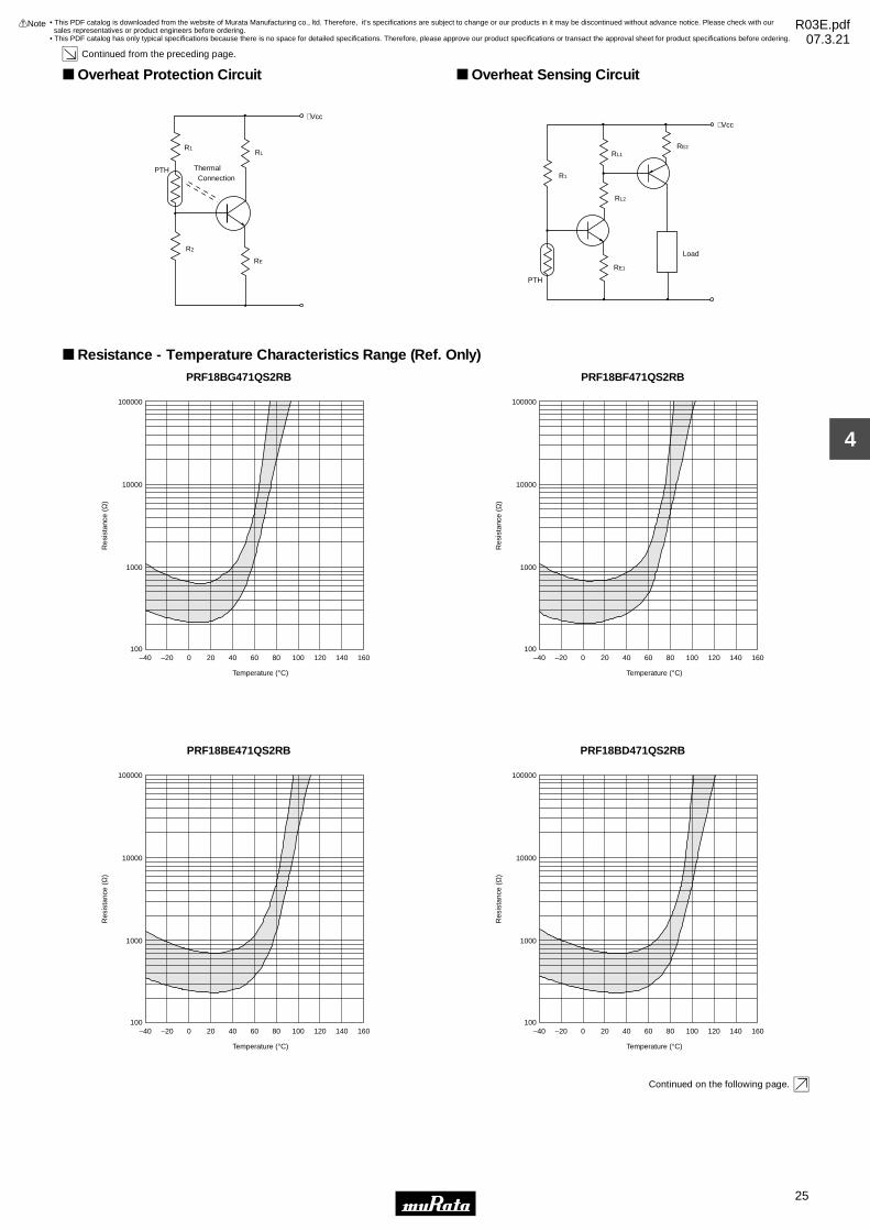
25
4
!Note • Please read rating and !CAUTION (for storage, operating, rating, soldering, mounting and handling) in this catalog to prevent smoking and/or burning, etc.• This catalog has only typical specifications because there is no space for detailed specifications. Therefore, please approve our product specifications or transact the approval sheet for product specifications before ordering.
Continued from the preceding page.
Overheat Protection Circuit
R1
R2
Thermal
+Vcc
RL
RE
ConnectionPTH
Overheat Sensing Circuit
R1
RL1
RL2
RE1
RE2
Load
+Vcc
PTH
Resistance - Temperature Characteristics Range (Ref. Only)PRF18BG471QS2RB
Temperature (°C)
Res
ista
nce
(Ω)
–20–40 0 20 40 60 80 100 120 140 160100
100000
10000
1000
PRF18BF471QS2RB
Temperature (°C)
Res
ista
nce
(Ω)
–20–40 0 20 40 60 80 100 120 140 160100
100000
10000
1000
PRF18BE471QS2RB
Temperature (°C)
Res
ista
nce
(Ω)
–20–40 0 20 40 60 80 100 120 140 160100
100000
10000
1000
PRF18BD471QS2RB
Temperature (°C)
Res
ista
nce
(Ω)
–20–40 0 20 40 60 80 100 120 140 160100
100000
10000
1000
Continued on the following page.
• This PDF catalog is downloaded from the website of Murata Manufacturing co., ltd. Therefore, it’s specifications are subject to change or our products in it may be discontinued without advance notice. Please check with our sales representatives or product engineers before ordering.
• This PDF catalog has only typical specifications because there is no space for detailed specifications. Therefore, please approve our product specifications or transact the approval sheet for product specifications before ordering.
!Note R03E.pdf07.3.21
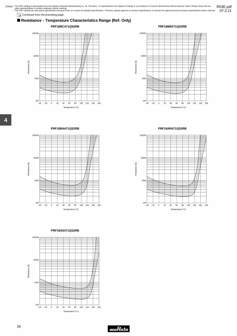
26
4
!Note • Please read rating and !CAUTION (for storage, operating, rating, soldering, mounting and handling) in this catalog to prevent smoking and/or burning, etc.• This catalog has only typical specifications because there is no space for detailed specifications. Therefore, please approve our product specifications or transact the approval sheet for product specifications before ordering.
Continued from the preceding page.
Resistance - Temperature Characteristics Range (Ref. Only)PRF18BC471QS2RB
Temperature (°C)
Res
ista
nce
(Ω)
–20–40 0 20 40 60 80 100 120 140 160100
100000
10000
1000
PRF18BB471QS2RB
Temperature (°C)
Res
ista
nce
(Ω)
–20–40 0 20 40 60 80 100 120 140 160100
100000
10000
1000
PRF18BA471QS2RB
Temperature (°C)
Res
ista
nce
(Ω)
–20–40 0 20 40 60 80 100 120 140 160100
100000
10000
1000
PRF18AR471QS2RB
Temperature (°C)
Res
ista
nce
(Ω)
–20–40 0 20 40 60 80 100 120 140 160100
100000
10000
1000
PRF18AS471QS2RB
Temperature (°C)
Res
ista
nce
(Ω)
–20–40 0 20 40 60 80 100 120 140 160100
100000
10000
1000
• This PDF catalog is downloaded from the website of Murata Manufacturing co., ltd. Therefore, it’s specifications are subject to change or our products in it may be discontinued without advance notice. Please check with our sales representatives or product engineers before ordering.
• This PDF catalog has only typical specifications because there is no space for detailed specifications. Therefore, please approve our product specifications or transact the approval sheet for product specifications before ordering.
!Note R03E.pdf07.3.21

Soldered PTC on Test Board∗ 1, and apply force on back side ofTest Board shown below:
Bending Speed: 1.0mm/sBending Strength: 2.0mmHold time: 5±1 secondsBoard Dimension: 100 A 40 A 1.6t mmBoard Material: Glass Epoxy
JIS C 5102 term 8.4Solder temp.: 230±5°CSolder: Sn63%/Pb37% (or 60%/40%)Soaking time: 3±0.5 secondsSoaking position: Until a whole electrode is soaked
Solder temp.: 260±5°CSolder: Sn63%/Pb37% (or 60%/40%)Flux: Containing less than 0.2wt% of chlorine.Soaking time: 10±0.5 secondsSoaking position: Until a whole electrode is soaked.Preheating: 150±5°C 3 minutes
Soldered PTC to PCB∗ 1
+150±3°C leave for 1000±12 hours
No. Item Rating Value Method of Examination
There is no detachment sign of electrode.
Normal appearanceResistance change: not to exceed ±20%∗ 2
Normal appearanceResistance change: not to exceed ±20%∗ 2
Min. 95% electrode is covered with new solder.Resistance change: not to exceed ±20%∗ 2
Resistance change: not exceed ±20%∗ 2
Normal appearance on the section showed by slanting line parts of the electrodes on the figure.
Normal appearanceResistance change: not to exceed ±20%∗ 2
The resistance value should be within the specified tolerance.Resistance Value(at 25˚C)
Adhesive Strength
Vibration Resistance
1
2
3
Resistance toBending ofSubstance
Solderability
Dry Heat Resistance
4
5
Soldering HeatResistance
6
7
EIAJ ET-7403 term 9Prepare soldered PTC to PCB ∗ 1 and add the force of 5.0N inthe direction shown below. (PTC=POSISTORr)
Soldered PTC to PCB∗ 1
Vibration: 10-2000-10Hz (20 minutes)Max. Amplitude: 3.0mm
Vibrate for 4 hours in each of 3 mutually perpendicular planes fora total of 12 hours. This test condition is according to "MIL-STD-204D"
After applying maximum operating voltage for 3 minutes and leaving for 2 hours at 25°C, measured by applying voltage ofless than 1.5Vdc (by a direct current of less than 10mA).
Soldered PTC to PCB∗ 1
-40±3°C leave for 1000±12 hoursCold Resistance8
Soldered PTC to PCB∗ 1
+85±3°C 80-85%RH leave for 1000±12 hoursDamp Heat Resistance
9
Soldered PTC to PCB∗ 1
Cycles: 1000 cycles
Soldered PTC to PCB∗ 1
85±3°C, 80-85%RH (in air), load max. operating voltage for1000±12 hours
Thermal Shock∗ 3
High TemperatureHumidity Load
10
11
PTC
F
F
Glass Epoxy PCB
50
45±245±2 Bending
20
R230
(in mm)PTC
Force
Electrode PTC
Continued on the following page.
Step12
-55+0, -3+125+3, -0
Temp. (°C)3030
Time (minutes)
27
4
!Note • Please read rating and !CAUTION (for storage, operating, rating, soldering, mounting and handling) in this catalog to prevent smoking and/or burning, etc.• This catalog has only typical specifications because there is no space for detailed specifications. Therefore, please approve our product specifications or transact the approval sheet for product specifications before ordering.
Chip Type of POSISTORr for Overheat Protection Specifications and Test Methods
• This PDF catalog is downloaded from the website of Murata Manufacturing co., ltd. Therefore, it’s specifications are subject to change or our products in it may be discontinued without advance notice. Please check with our sales representatives or product engineers before ordering.
• This PDF catalog has only typical specifications because there is no space for detailed specifications. Therefore, please approve our product specifications or transact the approval sheet for product specifications before ordering.
!Note R03E.pdf07.3.21

∗ 1 Above mentioned soldering is done under the following conditions at our site. • Glass-Epoxy PC board• Standard land dimension• Standard solder paste • Standard solder profile
Above conditions are mentioned in Notice.
∗ 2 Measure resistance after the test by applying voltage of less than 1.5Vdc by a direct current of less than 10mA after product is left at 25±2°C for 2 hours.
∗ 3 We cannot guarantee the resistance change in Thermal Shock (No.10) in case of defective mounting.
No. Item Rating Value Method of Examination
Normal appearanceResistance change: not to exceed ±20%∗ 2
High TemperatureLoad
12Soldered PTC to PCB∗ 1
+85±3°C (in air), load max. operating voltage for 1000±12hours.
Continued from the preceding page.
28
4
!Note • Please read rating and !CAUTION (for storage, operating, rating, soldering, mounting and handling) in this catalog to prevent smoking and/or burning, etc.• This catalog has only typical specifications because there is no space for detailed specifications. Therefore, please approve our product specifications or transact the approval sheet for product specifications before ordering.
Chip Type of POSISTORr for Overheat Protection Specifications and Test Methods
• This PDF catalog is downloaded from the website of Murata Manufacturing co., ltd. Therefore, it’s specifications are subject to change or our products in it may be discontinued without advance notice. Please check with our sales representatives or product engineers before ordering.
• This PDF catalog has only typical specifications because there is no space for detailed specifications. Therefore, please approve our product specifications or transact the approval sheet for product specifications before ordering.
!Note R03E.pdf07.3.21

29
5
!Note • Please read rating and !CAUTION (for storage, operating, rating, soldering, mounting and handling) in this catalog to prevent smoking and/or burning, etc.• This catalog has only typical specifications because there is no space for detailed specifications. Therefore, please approve our product specifications or transact the approval sheet for product specifications before ordering.
NTC/PTC Thermistors for AutomotivePTC Thermistor (POSISTORr) for Overcurrent Protection Chip Type 0805 (2012) Size
Overcurrent Protection device with resettable functionsuitable for current limiting resistor.This product is chip type PTC thermistor for overcurrent protection which is suitable for thefollowing•Countermeasure for short circuit testing•Current limiting resistor
Features1. Rapid operation to protect the circuit in an overcurrent condition abnormality such as a short circuit. By removing the overcurrent condition, these products automatically return to the initial condition and can be used repeatedly.2. Suitable for countermeasure to short circuit test in safety standard3. Stable resistance after operation due to ceramic PTC4. Similar size (0603 size) is possible due to the large capacity for electric power.5. Possible to use these products as current limiting resistors with overcurrent protection functions6. SMD type is helpful for miniaturizing circuits because of its small size and lightweight7. Lead is not contained in the terminations
L
T
Part NumberL W T
Dimensions (mm)e g
2.0±0.2 1.25±0.2 0.9±0.2 0.2 min. 0.5 min.2.0±0.2 1.25±0.2 1.25±0.2 0.2 min. 0.5 min.
PRG21_RAPRG21_RK
W
e eg
Part NumberMax.
Voltage(V)
Non-operatingCurrent (at +85°C)
(mA)
Non-operatingCurrent (at +105°C)
(mA)
Trip Current(at -40°C)
(mA)
Max.Current
(mA)
Resistance(at 25°C)
(ohm)
TemperatureRange
(°C)
PRG21AR420MS1RA 20 25 15 130 590 42 ±20% -40 to 105
PRG21AR220MS1RK 16 45 25 250 900 22 ±20% -40 to 105
Standard Land Pattern Dimensions
a
c
Solder resist
(in mm)b
LandChip
Part Number SolderingMethods Chip (LgW) a
Dimensions (mm)b c
Reflow Soldering 2.0g1.25 1.0-1.2 0.5-0.7 1.0-1.2PRG21
• This PDF catalog is downloaded from the website of Murata Manufacturing co., ltd. Therefore, it’s specifications are subject to change or our products in it may be discontinued without advance notice. Please check with our sales representatives or product engineers before ordering.
• This PDF catalog has only typical specifications because there is no space for detailed specifications. Therefore, please approve our product specifications or transact the approval sheet for product specifications before ordering.
!Note R03E.pdf07.3.21

30
5
!Note • Please read rating and !CAUTION (for storage, operating, rating, soldering, mounting and handling) in this catalog to prevent smoking and/or burning, etc.• This catalog has only typical specifications because there is no space for detailed specifications. Therefore, please approve our product specifications or transact the approval sheet for product specifications before ordering.
Protective Threshold Current Range PRG21AR220MS1RK
300
250
200
150
100
50
0
Cur
rent
(m
A)
Ambient Temperature (°C)
-50 -40 -30 -20 -10 0 10 20 30 40 50 60 70 80 90 100 110
Protective threshold current
Trip current
Non operating current
PRG21AR420MS1RA
160
140
120
100
80
60
40
20
0
Ambient Temperature (°C)
Cur
rent
(m
A)
Protective threshold current
-50 -40 -30 -20 -10 0 10 20 30 40 50 60 70 80 90 100 110
Trip current
Non operating current
Operating Time (Typical Curve)PRG21AR220MS1RK
Overcurrent (mA)
Ope
ratin
g Ti
me
(sec
.)
0 100 200 300 400 500 600
10
8
6
4
2
0
Y40°C
W25°CAmbient Temp.
W85°C
W105°C
PRG21AR420MS1RA
Overcurrent (mA)
Ope
ratin
g Ti
me
(sec
.)
0 100 200 300 400 500
10
8
6
4
2
0
Y40°C
W25°CAmbient Temp.
W85°C
W105°C
• This PDF catalog is downloaded from the website of Murata Manufacturing co., ltd. Therefore, it’s specifications are subject to change or our products in it may be discontinued without advance notice. Please check with our sales representatives or product engineers before ordering.
• This PDF catalog has only typical specifications because there is no space for detailed specifications. Therefore, please approve our product specifications or transact the approval sheet for product specifications before ordering.
!Note R03E.pdf07.3.21
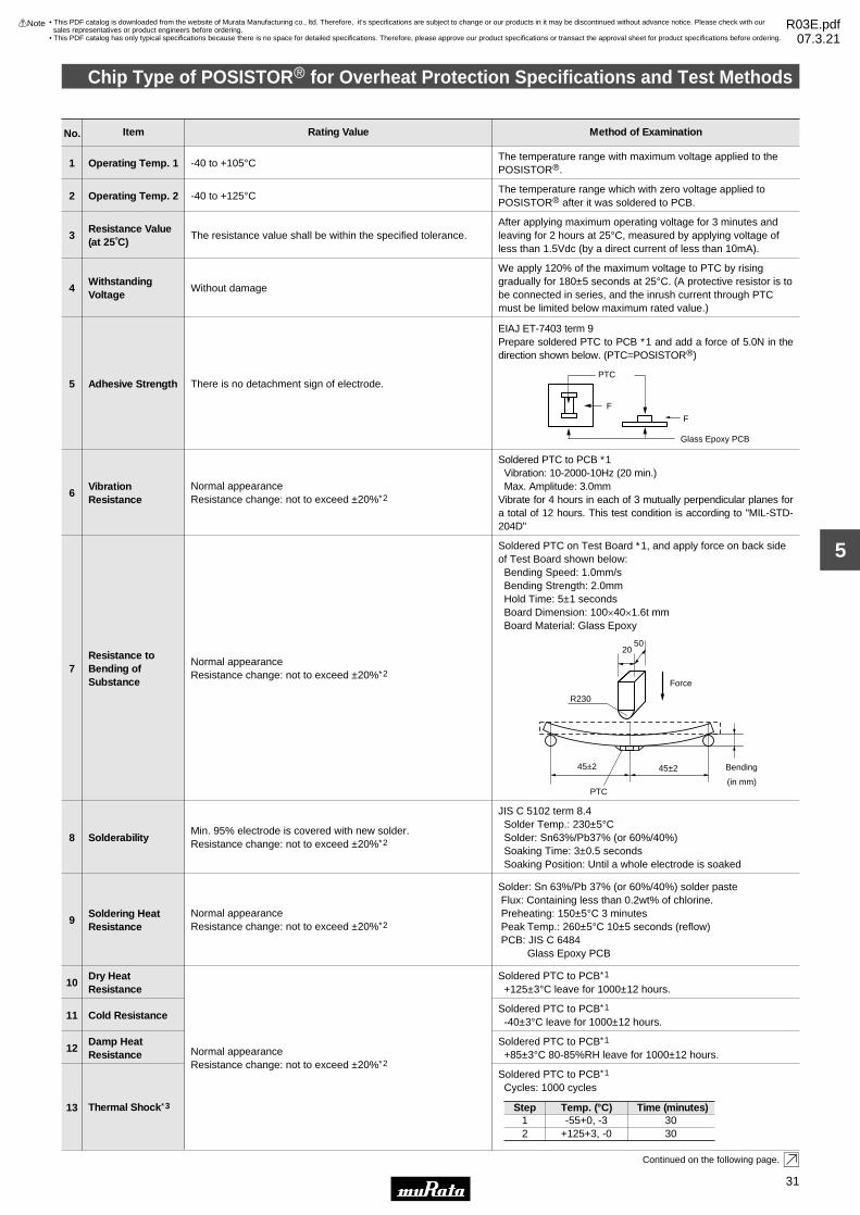
No. Item Rating Value Method of Examination
Normal appearanceResistance change: not to exceed ±20%∗ 2
-40 to +105°COperating Temp. 11The temperature range with maximum voltage applied to thePOSISTORr.
-40 to +125°COperating Temp. 22The temperature range which with zero voltage applied toPOSISTORr after it was soldered to PCB.
The resistance value shall be within the specified tolerance.Resistance Value(at 25˚C)
3After applying maximum operating voltage for 3 minutes andleaving for 2 hours at 25°C, measured by applying voltage ofless than 1.5Vdc (by a direct current of less than 10mA).
Without damageWithstanding Voltage
4
We apply 120% of the maximum voltage to PTC by rising gradually for 180±5 seconds at 25°C. (A protective resistor is tobe connected in series, and the inrush current through PTCmust be limited below maximum rated value.)
Soldered PTC on Test Board ∗ 1, and apply force on back sideof Test Board shown below:
Bending Speed: 1.0mm/sBending Strength: 2.0mmHold Time: 5±1 secondsBoard Dimension: 100A40A1.6t mmBoard Material: Glass Epoxy
JIS C 5102 term 8.4Solder Temp.: 230±5°CSolder: Sn63%/Pb37% (or 60%/40%)Soaking Time: 3±0.5 secondsSoaking Position: Until a whole electrode is soaked
Solder: Sn 63%/Pb 37% (or 60%/40%) solder pasteFlux: Containing less than 0.2wt% of chlorine.Preheating: 150±5°C 3 minutesPeak Temp.: 260±5°C 10±5 seconds (reflow)PCB: JIS C 6484
Glass Epoxy PCB
Soldered PTC to PCB∗ 1
+125±3°C leave for 1000±12 hours.
There is no detachment sign of electrode.
Normal appearanceResistance change: not to exceed ±20%∗ 2
Normal appearanceResistance change: not to exceed ±20%∗ 2
Min. 95% electrode is covered with new solder.Resistance change: not to exceed ±20%∗ 2
Normal appearanceResistance change: not to exceed ±20%∗ 2
Adhesive Strength
VibrationResistance
5
6
Resistance toBending ofSubstance
Solderability
Dry Heat Resistance
7
8
Soldering HeatResistance
9
10
EIAJ ET-7403 term 9Prepare soldered PTC to PCB ∗ 1 and add a force of 5.0N in thedirection shown below. (PTC=POSISTORr)
Soldered PTC to PCB ∗ 1Vibration: 10-2000-10Hz (20 min.)Max. Amplitude: 3.0mm
Vibrate for 4 hours in each of 3 mutually perpendicular planes fora total of 12 hours. This test condition is according to "MIL-STD-204D"
Soldered PTC to PCB∗ 1
-40±3°C leave for 1000±12 hours.Cold Resistance11
Soldered PTC to PCB∗ 1
+85±3°C 80-85%RH leave for 1000±12 hours.Damp Heat Resistance
12
PTC
F
F
Glass Epoxy PCB
50
45±245±2 Bending
20
R230
(in mm)PTC
Force
Continued on the following page.
Soldered PTC to PCB∗ 1
Cycles: 1000 cycles
Thermal Shock∗ 313 Step12
-55+0, -3+125+3, -0
Temp. (°C)3030
Time (minutes)
31
5
!Note • Please read rating and !CAUTION (for storage, operating, rating, soldering, mounting and handling) in this catalog to prevent smoking and/or burning, etc.• This catalog has only typical specifications because there is no space for detailed specifications. Therefore, please approve our product specifications or transact the approval sheet for product specifications before ordering.
Chip Type of POSISTORr for Overheat Protection Specifications and Test Methods
• This PDF catalog is downloaded from the website of Murata Manufacturing co., ltd. Therefore, it’s specifications are subject to change or our products in it may be discontinued without advance notice. Please check with our sales representatives or product engineers before ordering.
• This PDF catalog has only typical specifications because there is no space for detailed specifications. Therefore, please approve our product specifications or transact the approval sheet for product specifications before ordering.
!Note R03E.pdf07.3.21

∗ 1 Above mentioned soldering is done under the following conditions at our site. • Glass-Epoxy PC board• Standard land dimension• Standard solder paste • Standard solder profile
Above conditions are mentioned in Notice.
∗ 2 Measure resistance after the test by applying voltage of less than 1.5Vdc by a direct current of less than 10mA after product is left at 25±2°C for 2 hours.
∗ 3 We cannot guarantee the resistance change in Thermal Shock (No.10) in case of defective mounting.
No. Item Rating Value Method of Examination
Normal appearanceResistance change: not to exceed ±20%∗ 2
High TemperatureLoad
15
Soldered PTC to PCB∗ 1
125±3°C (in air), PTC is applied max. operating voltage for 1.5 hours on and 0.5 hours off. This cycle is repeated for 1000±10hours.
Continued from the preceding page.
Soldered PTC to PCB∗ 1
85±3°C, 80-85%RH (in air), load max. operating voltage for1000±12 hours.
High TemperatureHumidity Load
14
32
5
!Note • Please read rating and !CAUTION (for storage, operating, rating, soldering, mounting and handling) in this catalog to prevent smoking and/or burning, etc.• This catalog has only typical specifications because there is no space for detailed specifications. Therefore, please approve our product specifications or transact the approval sheet for product specifications before ordering.
Chip Type of POSISTORr for Overheat Protection Specifications and Test Methods
• This PDF catalog is downloaded from the website of Murata Manufacturing co., ltd. Therefore, it’s specifications are subject to change or our products in it may be discontinued without advance notice. Please check with our sales representatives or product engineers before ordering.
• This PDF catalog has only typical specifications because there is no space for detailed specifications. Therefore, please approve our product specifications or transact the approval sheet for product specifications before ordering.
!Note R03E.pdf07.3.21
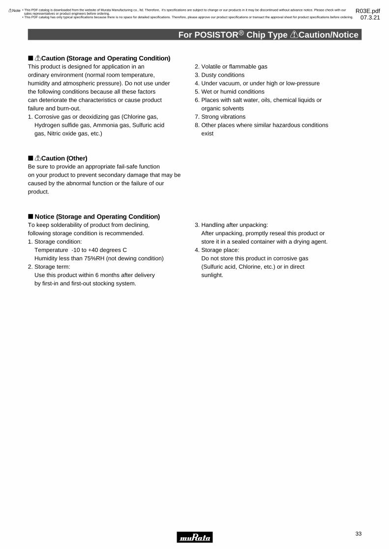
For POSISTORr Chip Type !Caution/Notice
33
5
!Note • Please read rating and !CAUTION (for storage, operating, rating, soldering, mounting and handling) in this catalog to prevent smoking and/or burning, etc.• This catalog has only typical specifications because there is no space for detailed specifications. Therefore, please approve our product specifications or transact the approval sheet for product specifications before ordering.
!Caution (Storage and Operating Condition)This product is designed for application in an ordinary environment (normal room temperature, humidity and atmospheric pressure). Do not use under the following conditions because all these factors can deteriorate the characteristics or cause product failure and burn-out.1. Corrosive gas or deoxidizing gas (Chlorine gas, Hydrogen sulfide gas, Ammonia gas, Sulfuric acid gas, Nitric oxide gas, etc.)
2. Volatile or flammable gas3. Dusty conditions4. Under vacuum, or under high or low-pressure5. Wet or humid conditions6. Places with salt water, oils, chemical liquids or organic solvents7. Strong vibrations8. Other places where similar hazardous conditions exist
!Caution (Other)Be sure to provide an appropriate fail-safe function on your product to prevent secondary damage that may becaused by the abnormal function or the failure of our product.
Notice (Storage and Operating Condition)To keep solderability of product from declining, following storage condition is recommended.1. Storage condition: Temperature -10 to +40 degrees C Humidity less than 75%RH (not dewing condition)2. Storage term: Use this product within 6 months after delivery by first-in and first-out stocking system.
3. Handling after unpacking: After unpacking, promptly reseal this product or store it in a sealed container with a drying agent.4. Storage place: Do not store this product in corrosive gas (Sulfuric acid, Chlorine, etc.) or in direct sunlight.
• This PDF catalog is downloaded from the website of Murata Manufacturing co., ltd. Therefore, it’s specifications are subject to change or our products in it may be discontinued without advance notice. Please check with our sales representatives or product engineers before ordering.
• This PDF catalog has only typical specifications because there is no space for detailed specifications. Therefore, please approve our product specifications or transact the approval sheet for product specifications before ordering.
!Note R03E.pdf07.3.21

(2) DryingAfter cleaning, promptly dry this product.
To remove the flux after soldering, observe the following points in order to avoid deterioration of the characteristics or any change to the external electrodes quality.(1) Cleaning Conditions
2-propanol
Less than 5 minutesat room temp.
orLess than 2 minutes
at 40˚C max.
Less than 1 minute20W/L Frequencyof several 10kHz
to 100kHz.
Solvent Dipping Cleaning Ultrasonic Cleaning
A sufficient cleaning should be applied to remove flux completely.
In your mounting process, observe the following points in order to avoid deterioration of the characteristics or destruction of this product. The mounting quality of this product may also be affected by the mounting conditions, shown in the points below.(1) Printing Conditions of Solder Paste
(a) Recommended thickness of solder paste printing should be from 0.15 to 0.20mm.
(b) After soldering, the solder fillet should be a height from 0.2 mm to the thickness of this product (see the figure at right).
(c) Too much solder gives too strong mechanical stress to this product. Such stress may cause cracking or other mechanical damage. Also, it can destroy the electrical performance of this product.
0.2mm V T V E
T
Solder
Solder
Electrode
1. Solder and Flux
2. Cleaning Conditions and Drying
3. Soldering Conditions
(1) Solder Paste(a) Flow Soldering: Use Sn:Pb=60:40wt%,
Sn:Pb=63:37wt%, Sn:Ag:Cu=96.5:3.0:0.5wt% or equivalent type of solder.
(b) Reflow Soldering: Use Sn:Pb=60:40wt%, Sn:Pb=63:37wt%, Sn:Ag:Cu=96.5:3.0:0.5wt% or equivalent type of solder paste. For your reference, we are using '63Sn/37Pb RMA9086 90-3-M18', manufactured by Alpha Metals Japan Ltd., '96.5Sn/3.0Ag/0.5Cu M705-221BM5-42-11', manufactured by Senju Metal Industry Co., Ltd. for any Internal tests of this product.
(2) FluxUse rosin-based flux. Do not use strong acidic flux (with halide content exceeding 0.2wt%).
E
Continued on the following page.
Notice (Soldering and Mounting) 0603 (1608) Size
For POSISTORr Chip Type !Caution/Notice
34
5
!Note • Please read rating and !CAUTION (for storage, operating, rating, soldering, mounting and handling) in this catalog to prevent smoking and/or burning, etc.• This catalog has only typical specifications because there is no space for detailed specifications. Therefore, please approve our product specifications or transact the approval sheet for product specifications before ordering.
• This PDF catalog is downloaded from the website of Murata Manufacturing co., ltd. Therefore, it’s specifications are subject to change or our products in it may be discontinued without advance notice. Please check with our sales representatives or product engineers before ordering.
• This PDF catalog has only typical specifications because there is no space for detailed specifications. Therefore, please approve our product specifications or transact the approval sheet for product specifications before ordering.
!Note R03E.pdf07.3.21
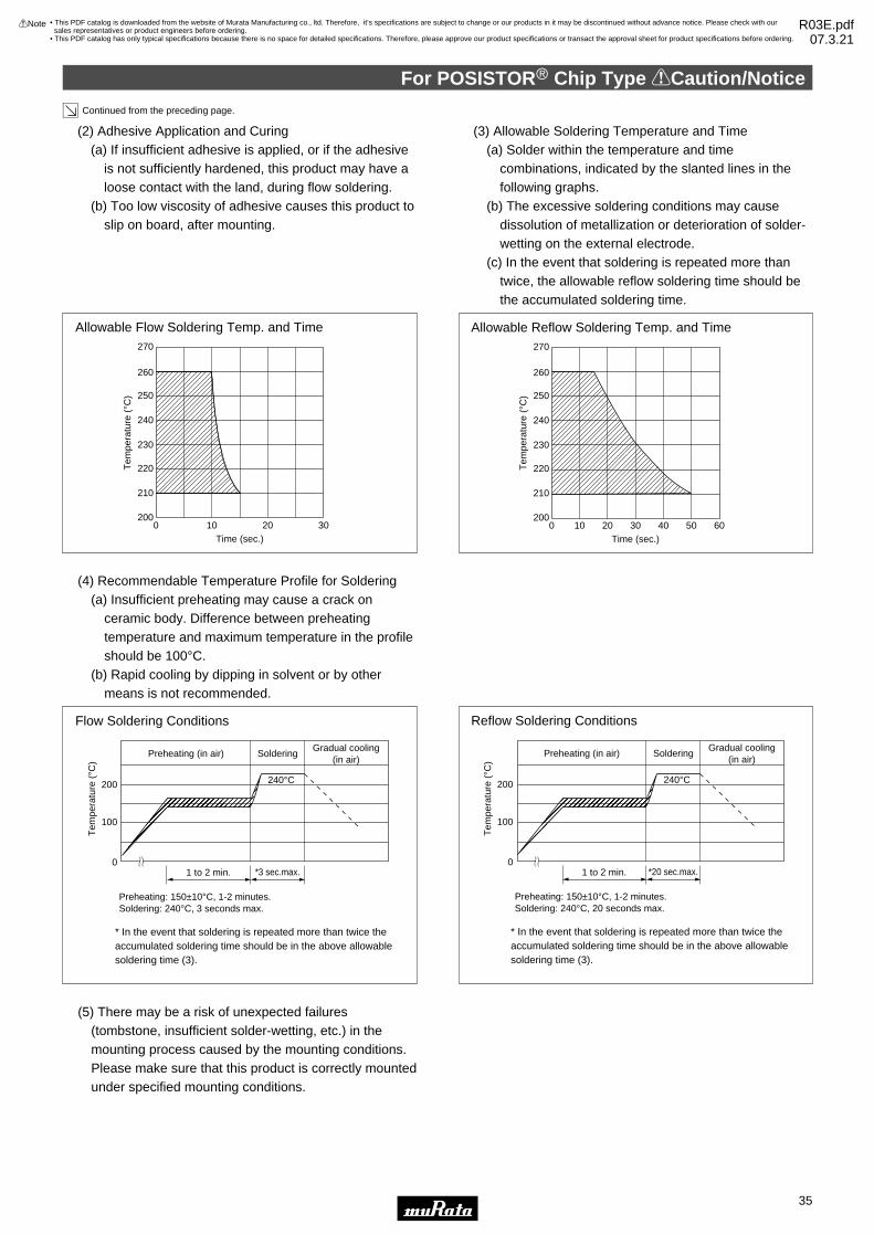
Continued from the preceding page.
Time (sec.)0 10 20 30 40 50 60
260
250
270
240
230
220
210
200
Allowable Reflow Soldering Temp. and Time
Tem
pera
ture
(°C
)
(2) Adhesive Application and Curing(a) If insufficient adhesive is applied, or if the adhesive
is not sufficiently hardened, this product may have a loose contact with the land, during flow soldering.
(b) Too low viscosity of adhesive causes this product to slip on board, after mounting.
(3) Allowable Soldering Temperature and Time(a) Solder within the temperature and time
combinations, indicated by the slanted lines in the following graphs.
(b) The excessive soldering conditions may cause dissolution of metallization or deterioration of solder-wetting on the external electrode.
(c) In the event that soldering is repeated more than twice, the allowable reflow soldering time should be the accumulated soldering time.
(4) Recommendable Temperature Profile for Soldering(a) Insufficient preheating may cause a crack on
ceramic body. Difference between preheating temperature and maximum temperature in the profile should be 100°C.
(b) Rapid cooling by dipping in solvent or by other means is not recommended.
(5) There may be a risk of unexpected failures (tombstone, insufficient solder-wetting, etc.) in the mounting process caused by the mounting conditions. Please make sure that this product is correctly mounted under specified mounting conditions.
QQRRRSSSTUUVVWXXX YYYZ[[\\\ ]]^^^__`¢¢£££¤¤¤¥¦¦§§¨©©© ªªª«¬¬ ®®¯¯¯°°±±
SolderingGradual cooling
(in air)Preheating (in air)
1 to 2 min.
200
100
0
240°C
Flow Soldering Conditions
* In the event that soldering is repeated more than twice theaccumulated soldering time should be in the above allowablesoldering time (3).
*3 sec.max.
Preheating: 150±10°C, 1-2 minutes.Soldering: 240°C, 3 seconds max.
Tem
pera
ture
(°C
)
QQRRSSTT UUUVVWXXYYZ[[\\]^^___`¢¢££¤¤¥¥ ¦¦¦§§¨©©ªª«¬¬®¯¯°°°±±
SolderingGradual cooling
(in air)Preheating (in air)
1 to 2 min.
200
100
0
240°C
Reflow Soldering Conditions
* In the event that soldering is repeated more than twice theaccumulated soldering time should be in the above allowablesoldering time (3).
*20 sec.max.
Preheating: 150±10°C, 1-2 minutes.Soldering: 240°C, 20 seconds max.
Tem
pera
ture
(°C
)
Time (sec.)0 10 20 30
260
250
270
240
230
220
210
200
Allowable Flow Soldering Temp. and Time
Tem
pera
ture
(°C
)
For POSISTORr Chip Type !Caution/Notice
35
5
!Note • Please read rating and !CAUTION (for storage, operating, rating, soldering, mounting and handling) in this catalog to prevent smoking and/or burning, etc.• This catalog has only typical specifications because there is no space for detailed specifications. Therefore, please approve our product specifications or transact the approval sheet for product specifications before ordering.
• This PDF catalog is downloaded from the website of Murata Manufacturing co., ltd. Therefore, it’s specifications are subject to change or our products in it may be discontinued without advance notice. Please check with our sales representatives or product engineers before ordering.
• This PDF catalog has only typical specifications because there is no space for detailed specifications. Therefore, please approve our product specifications or transact the approval sheet for product specifications before ordering.
!Note R03E.pdf07.3.21
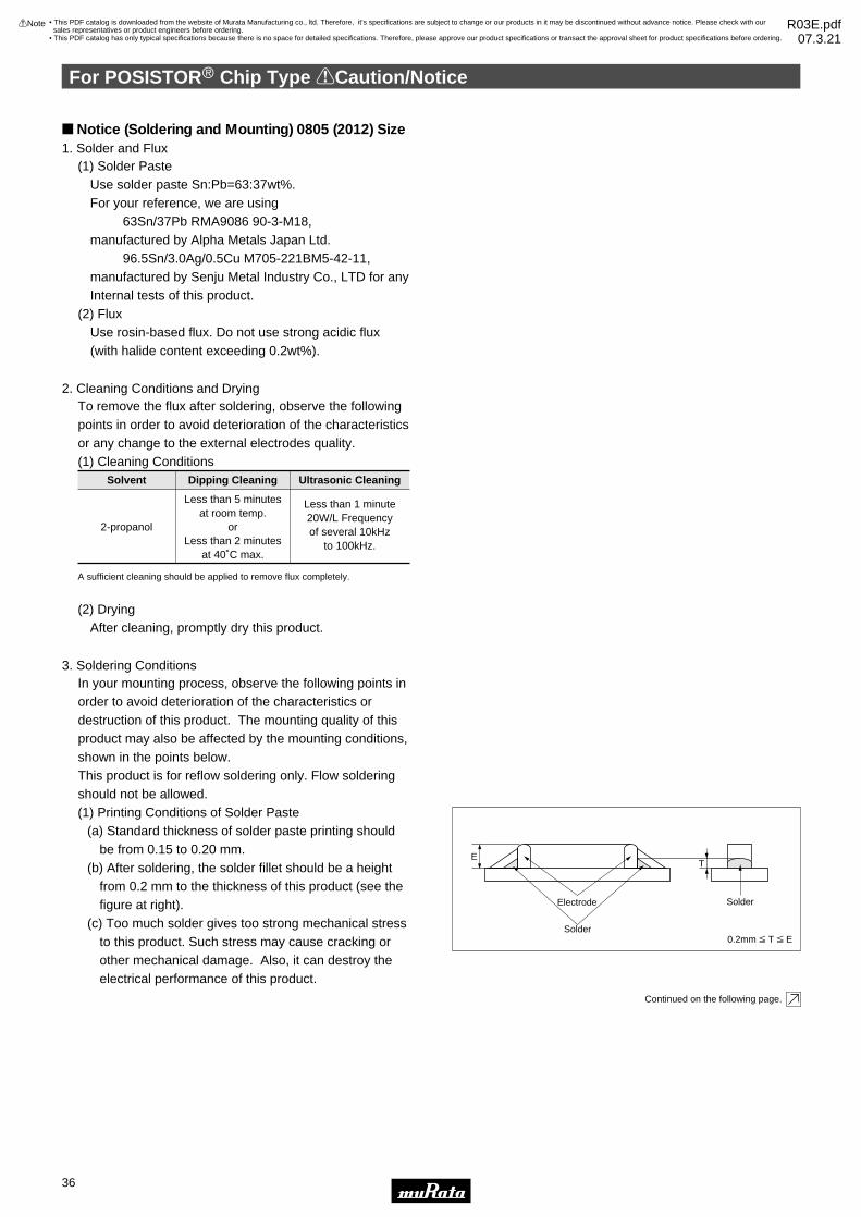
(2) DryingAfter cleaning, promptly dry this product.
To remove the flux after soldering, observe the following points in order to avoid deterioration of the characteristics or any change to the external electrodes quality.(1) Cleaning Conditions
2-propanol
Less than 5 minutesat room temp.
orLess than 2 minutes
at 40˚C max.
Less than 1 minute20W/L Frequencyof several 10kHz
to 100kHz.
Solvent Dipping Cleaning Ultrasonic Cleaning
A sufficient cleaning should be applied to remove flux completely.
(1) Printing Conditions of Solder Paste(a) Standard thickness of solder paste printing should
be from 0.15 to 0.20 mm.(b) After soldering, the solder fillet should be a height
from 0.2 mm to the thickness of this product (see the figure at right).
(c) Too much solder gives too strong mechanical stress to this product. Such stress may cause cracking or other mechanical damage. Also, it can destroy the electrical performance of this product.
In your mounting process, observe the following points in order to avoid deterioration of the characteristics or destruction of this product. The mounting quality of this product may also be affected by the mounting conditions, shown in the points below.This product is for reflow soldering only. Flow soldering should not be allowed.
0.2mm V T V E
T
Solder
Solder
Electrode
1. Solder and Flux
2. Cleaning Conditions and Drying
3. Soldering Conditions
(1) Solder PasteUse solder paste Sn:Pb=63:37wt%.For your reference, we are using
63Sn/37Pb RMA9086 90-3-M18, manufactured by Alpha Metals Japan Ltd.
96.5Sn/3.0Ag/0.5Cu M705-221BM5-42-11, manufactured by Senju Metal Industry Co., LTD for any Internal tests of this product.
(2) FluxUse rosin-based flux. Do not use strong acidic flux (with halide content exceeding 0.2wt%).
E
Continued on the following page.
Notice (Soldering and Mounting) 0805 (2012) Size
For POSISTORr Chip Type !Caution/Notice
36
5
!Note • Please read rating and !CAUTION (for storage, operating, rating, soldering, mounting and handling) in this catalog to prevent smoking and/or burning, etc.• This catalog has only typical specifications because there is no space for detailed specifications. Therefore, please approve our product specifications or transact the approval sheet for product specifications before ordering.
• This PDF catalog is downloaded from the website of Murata Manufacturing co., ltd. Therefore, it’s specifications are subject to change or our products in it may be discontinued without advance notice. Please check with our sales representatives or product engineers before ordering.
• This PDF catalog has only typical specifications because there is no space for detailed specifications. Therefore, please approve our product specifications or transact the approval sheet for product specifications before ordering.
!Note R03E.pdf07.3.21
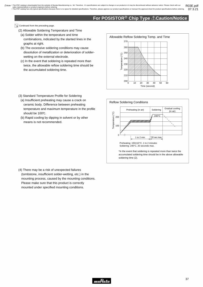
(3) Standard Temperature Profile for Soldering(a) Insufficient preheating may cause a crack on
ceramic body. Difference between preheating temperature and maximum temperature in the profile should be 100D.
(b) Rapid cooling by dipping in solvent or by other means is not recommended.
QQRRSTT UUUVWXXYZ[[\\]^^___`¢¢££¤¥¥ ¦¦¦§©©ª«¬¬®¯¯°°°±
SolderingGradual cooling
(in air)Preheating (in air)
1 to 2 min.
200
100
0
240°C
Reflow Soldering Conditions
*In the event that soldering is repeated more than twice theaccumulated soldering time should be in the above allowablesoldering time (2).
*20 sec.max.
Preheating: 150T10°C, 1 to 2 minutesSoldering: 240°C, 20 seconds max.
(4) There may be a risk of unexpected failures (tombstone, insufficient solder-wetting, etc.) in the mounting process, caused by the mounting conditions. Please make sure that this product is correctly mounted under specified mounting conditions.
(2) Allowable Soldering Temperature and Time(a) Solder within the temperature and time
combinations, indicated by the slanted lines in the graphs at right.
(b) The excessive soldering conditions may cause dissolution of metallization or deterioration of solder-wetting on the external electrode.
(c) In the event that soldering is repeated more than twice, the allowable reflow soldering time should be the accumulated soldering time.
Time (second)0 10 20 30 40 50 60
260
250
270
240
230
220
210
200
Continued from the preceding page.
Allowable Reflow Soldering Temp. and Time
Tem
pera
ture
(°C
)
Tem
pera
ture
(°C
)
For POSISTORr Chip Type !Caution/Notice
37
5
!Note • Please read rating and !CAUTION (for storage, operating, rating, soldering, mounting and handling) in this catalog to prevent smoking and/or burning, etc.• This catalog has only typical specifications because there is no space for detailed specifications. Therefore, please approve our product specifications or transact the approval sheet for product specifications before ordering.
• This PDF catalog is downloaded from the website of Murata Manufacturing co., ltd. Therefore, it’s specifications are subject to change or our products in it may be discontinued without advance notice. Please check with our sales representatives or product engineers before ordering.
• This PDF catalog has only typical specifications because there is no space for detailed specifications. Therefore, please approve our product specifications or transact the approval sheet for product specifications before ordering.
!Note R03E.pdf07.3.21

For POSISTORr Chip Type !Caution/Notice
38
5
!Note • Please read rating and !CAUTION (for storage, operating, rating, soldering, mounting and handling) in this catalog to prevent smoking and/or burning, etc.• This catalog has only typical specifications because there is no space for detailed specifications. Therefore, please approve our product specifications or transact the approval sheet for product specifications before ordering.
Notice (Handling)1. Do not give this product a strong press-force nor a
mechanical shock, because such mechanical forces may cause cracking or chipping of this ceramic product.
Locate chip horizontal to the direction in which stress acts
Put this product on the PC Board near the Slit, not near the Perforation Holes.Keep this product on the PC Board away from the Separation Line.
Worst A-C-B-D Better
Component Direction
Chip Mounting Close to Board Separation Point
A
B
D
C
Perforation Holes
Slit
Separation Line
2. Rapid cooling or heating during soldering is not recommended.
Such treatment may destroy the element.
3. Resin coatingPlease select a resin material with minimum hardness. Shrinkage is much less if selecting a resin material.
4. Location on Printed Circuit Board (PC Board)Choose a mounting position that minimizes the stress imposed on the chip during flexing or bending of the board.
(Worse) (Better)
• This PDF catalog is downloaded from the website of Murata Manufacturing co., ltd. Therefore, it’s specifications are subject to change or our products in it may be discontinued without advance notice. Please check with our sales representatives or product engineers before ordering.
• This PDF catalog has only typical specifications because there is no space for detailed specifications. Therefore, please approve our product specifications or transact the approval sheet for product specifications before ordering.
!Note R03E.pdf07.3.21

39
6
!Note • Please read rating and !CAUTION (for storage, operating, rating, soldering, mounting and handling) in this catalog to prevent smoking and/or burning, etc.• This catalog has only typical specifications because there is no space for detailed specifications. Therefore, please approve our product specifications or transact the approval sheet for product specifications before ordering.
NTC/PTC Thermistors for AutomotivePTC Thermistor (POSISTORr) for Overcurrent Protection Lead Type
16V Series
This low-voltage, low-resistance type "POSISTOR" is a circuit protector whose resistance value in normaloperation is very low and in abnormal situations likemotor lock or short circuit, will be increased torestrain over current. This "POSISTOR" is mostsuitable for low-voltage circuits and motor protectionfor automotive grade applications.
Features1. Best suited to meet the requirements for power supply and motor protection. Error-free operation is assured by rush current.2. Circuit is protected until current is turned off.3. Restores the original low resistance value automatically once the overload is removed.4. Non-contact design leads to long life and no noise. Durable and strong against mechanical vibration and shock because it is a solid element.5. Lead (Pb) is not contained in the terminations.
F±1.5 φd±0.05
D max. T max.
H m
ax.
4.0±
1.5
(in mm)
Part NumberMax.
Voltage(V)
Non-operatingCurrent (at +85°C)
(mA)
Trip Current(at -30°C)
(mA)
Max.Current
(A)
Resistance(at 25°C)
(ohm)
TemperatureRange
(°C)
BodyDiameter (D)
(mm)
Thickness(T)
(mm)
Height(H)
(mm)
LeadSpace (F)
(mm)
LeadDiameter
(phi d)(mm)
PTGL5SAR1R0M1B51B0 16 252 1095 2.0 1.0 ±20% -30 to 85 6.0 3.5 9.5 5.0 0.6
PTGL6SAR0R8M1B51B0 16 274 1193 3.0 0.8 ±20% -30 to 85 6.5 3.5 10.0 5.0 0.6
PTGL7SARR47M1B51B0 16 376 1634 5.0 0.47 ±20% -30 to 85 7.5 3.5 12.0 5.0 0.6
PTGL9SARR33M1B51B0 16 466 2026 7.0 0.33 ±20% -30 to 85 9.0 3.5 14.0 5.0 0.6
PTGLASARR27M1B51B0 16 545 2369 8.0 0.27 ±20% -30 to 85 10.1 3.5 15.0 5.0 0.6
PTGLCSAR0R2M1B51B0 16 692 3006 9.0 0.2 ±20% -30 to 85 11.3 3.5 16.0 5.0 0.6
PTGLESARR15M1B51B0 16 820 3561 10 0.15 ±20% -30 to 85 13.5 3.5 18.5 5.0 0.6
Maximum Current shows typical capacities of the transformer which can be used.
Taping type of part numbers with "A0" is available (Except PTGLESARR15M1B51B0).
• This PDF catalog is downloaded from the website of Murata Manufacturing co., ltd. Therefore, it’s specifications are subject to change or our products in it may be discontinued without advance notice. Please check with our sales representatives or product engineers before ordering.
• This PDF catalog has only typical specifications because there is no space for detailed specifications. Therefore, please approve our product specifications or transact the approval sheet for product specifications before ordering.
!Note R03E.pdf07.3.21

40
6
!Note • Please read rating and !CAUTION (for storage, operating, rating, soldering, mounting and handling) in this catalog to prevent smoking and/or burning, etc.• This catalog has only typical specifications because there is no space for detailed specifications. Therefore, please approve our product specifications or transact the approval sheet for product specifications before ordering.
30-140V Series
New leaded type POSISTOR for overcurrent protection as automotive grade can be used with wide temperature range. This product is suitable for short-protect and current limiting resistor on power supply equipment.
Features1. This product has useful Protective threshold current range with wide temperature range.2. Small fluctuation in the circuit due to resistance tolerance +/-10%.3. Quick operating time due to small size compared with conventional products.4. Best suited to meet the requirements for power supply and motor protector. Error-free operations are assured by rush current.5. Circuit is protected until current is turned off.6. Restores the original low resistance value automatically once the overload is removed.7. Non-contact design leads to long life and no noise. Durable and strong against mechanical vibration and shock because it is a solid element.8. Lead (Pb) is not contained in the terminations.
F±1.5 φd±0.05
D max. T max.
H m
ax.
4.0±
1.5
(in mm)
Part NumberMax.
Voltage(V)
Non-operatingCurrent (at +85°C)
(mA)
Non-operatingCurrent (at +105°C)
(mA)
Trip Current(at -40°C)
(mA)
Max.Current
(A)
Resistance(at 25°C)
(ohm)
TemperatureRange
(°C)
BodyDiameter (D)
(mm)
Height(H)
(mm)
LeadSpace (F)
(mm)
LeadDiameter
(phi d)(mm)
PTGL4SAS100K2N51B0 30 92 65 261 1.5 10 ±10% -40 to 125 4.5 9.5 5.0 0.5
PTGL4SAS100K2B51B0 30 127 89 359 2.0 10 ±10% -40 to 125 4.5 9.5 5.0 0.6
PTGL5SAS3R9K2B51B0 30 204 143 576 3.5 3.9 ±10% -40 to 125 5.5 10.5 5.0 0.6
PTGL7SAS2R7K2B51B0 30 255 179 720 4.5 2.7 ±10% -40 to 125 7.3 12.3 5.0 0.6
PTGL7SAS1R8K2B51B0 30 319 223 902 5.0 1.8 ±10% -40 to 125 7.3 12.3 5.0 0.6
PTGL9SAS1R2K2B51B0 30 422 296 1193 6.0 1.2 ±10% -40 to 125 9.3 14.3 5.0 0.6
PTGLCSAS0R8K2B51B0 30 520 364 1470 7.0 0.8 ±10% -40 to 125 11.5 16.5 5.0 0.6
PTGL4SAS100K3B51B0 51 128 89 361 1.0 10 ±10% -40 to 125 4.5 9.5 5.0 0.6
PTGL5SAS6R8K3B51B0 51 149 105 422 1.5 6.8 ±10% -40 to 125 5.5 10.5 5.0 0.6
PTGL7SAS3R3K3B51B0 51 233 163 659 3.0 3.3 ±10% -40 to 125 7.3 12.3 5.0 0.6
PTGL9SAS2R2K3B51B0 51 313 219 885 4.0 2.2 ±10% -40 to 125 9.3 14.3 5.0 0.6
PTGLCSAS1R2K3B51B0 51 449 315 1270 5.0 1.2 ±10% -40 to 125 11.5 16.5 5.0 0.6
PTGL4SAS220K4N51B0 60 67 47 190 1.0 22 ±10% -40 to 125 4.5 9.5 5.0 0.5
PTGL4SAS220K4B51B0 60 87 61 246 1.0 22 ±10% -40 to 125 4.5 9.5 5.0 0.6
PTGL5SAS100K4B51B0 60 129 90 364 1.5 10 ±10% -40 to 125 5.5 10.5 5.0 0.6
PTGL7SAS5R6K4N51B0 60 142 99 400 2.2 5.6 ±10% -40 to 125 7.3 12.3 5.0 0.5
PTGL7SAS5R6K4B51B0 60 174 122 492 3.0 5.6 ±10% -40 to 125 7.3 12.3 5.0 0.6
PTGL9SAS3R3K4B51B0 60 253 177 714 4.0 3.3 ±10% -40 to 125 9.3 14.3 5.0 0.6
PTGLCSAS2R2K4B51B0 60 334 234 942 5.0 2.2 ±10% -40 to 125 11.5 16.5 5.0 0.6
PTGL4SAS560K6B51B0 140 56 39 159 0.5 56 ±10% -40 to 125 5.5 10.5 5.0 0.6
PTGL5SAS270K6B51B0 140 80 56 227 1.0 27 ±10% -40 to 125 5.5 10.5 5.0 0.6
PTGL7SAS150K6B51B0 140 112 79 317 1.5 15 ±10% -40 to 125 7.3 12.3 5.0 0.6
PTGL9SAS120K6B51B0 140 146 102 413 2.0 12 ±10% -40 to 125 9.3 14.3 5.0 0.6
PTGL9SAS7R6K6B51B0 140 172 121 486 2.2 7.6 ±10% -40 to 125 9.3 14.3 5.0 0.6
PTGLCSAS4R7K6B51B0 140 236 165 666 3.5 4.7 ±10% -40 to 125 11.5 16.5 5.0 0.6
Maximum Current shows typical capacities of the transformer which can be used.
These series are recognized by UL.
Taping type is also available (PTGL_A0 series).
Thickness(T)
(mm)
3.5
3.5
3.5
3.5
3.5
3.5
3.5
3.5
3.5
3.5
3.5
3.5
3.5
3.5
3.5
3.5
3.5
3.5
3.5
4.5
4.5
4.5
4.5
4.5
4.5
• This PDF catalog is downloaded from the website of Murata Manufacturing co., ltd. Therefore, it’s specifications are subject to change or our products in it may be discontinued without advance notice. Please check with our sales representatives or product engineers before ordering.
• This PDF catalog has only typical specifications because there is no space for detailed specifications. Therefore, please approve our product specifications or transact the approval sheet for product specifications before ordering.
!Note R03E.pdf07.3.21

41
6
!Note • Please read rating and !CAUTION (for storage, operating, rating, soldering, mounting and handling) in this catalog to prevent smoking and/or burning, etc.• This catalog has only typical specifications because there is no space for detailed specifications. Therefore, please approve our product specifications or transact the approval sheet for product specifications before ordering.
Protective Threshold Current Range (16V Series)PTGL5SAR1R0M1B51B0
1400
1200
1000
800
600
400
200
0-40 -30 -20 -10 0 10 20 30 40 50 60 70 80 90
Ambient Temperature (°C)
Cur
rent
(m
A)
Trip current
Non operating current
Protective threshold current
PTGL6SAR0R8M1B51B0
1400
1200
1000
800
600
400
200
0-40 -30 -20 -10 0 10 20 30 40 50 60 70 80 90
Ambient Temperature (°C)
Cur
rent
(m
A)
Trip current
Non operating current
Protective threshold current
PTGL7SARR47M1B51B0
2000
1800
1600
1400
1200
1000
800
600
400
200
0-40 -30 -20 -10 0 10 20 30 40 50 60 70 80 90
Ambient Temperature (°C)
Cur
rent
(m
A)
Protective threshold current
Trip current
Non operating current
PTGL9SARR33M1B51B0
2600
2400
2200
2000
1800
1600
1400
1200
1000
800
600
400
200
0-40 -30 -20 -10 0 10 20 30 40 50 60 70 80 90
Ambient Temperature (°C)
Cur
rent
(m
A)
Trip current
Non operating current
Protective threshold current
PTGLASARR27M1B51B0
3000
2800
2600
2400
2200
2000
1800
1600
1400
1200
1000
800
600
400
200
0-40 -30 -20 -10 0 10 20 30 40 50 60 70 80 90
Ambient Temperature (°C)
Cur
rent
(m
A)
Trip current
Non operating current
Protective threshold current
PTGLCSAR0R2M1B51B0
4000
3500
3000
2500
2000
1500
1000
500
0-40 -30 -20 -10 0 10 20 30 40 50 60 70 80 90
Ambient Temperature (°C)
Cur
rent
(m
A)
Trip current
Non operating current
Protective threshold current
PTGLESARR15M1B51B0
4000
3500
3000
2500
2000
1500
1000
500
0-40 -30 -20 -10 0 10 20 30 40 50 60 70 80 90
Ambient Temperature (°C)
Cur
rent
(m
A)
Trip current
Non operating current
Protective threshold current
Protective Threshold Current Range (30V Series)PTGL4SAS100K2N51B0
300
250
200
150
100
50
0-50 -40 -30 -20 -10 0 10 20 30 40 50 60 70 80 90 100 110
Ambient Temperature (°C)
Cur
rent
(m
A) Protective
threshold current
Trip current
Non operating current
Continued on the following page.
• This PDF catalog is downloaded from the website of Murata Manufacturing co., ltd. Therefore, it’s specifications are subject to change or our products in it may be discontinued without advance notice. Please check with our sales representatives or product engineers before ordering.
• This PDF catalog has only typical specifications because there is no space for detailed specifications. Therefore, please approve our product specifications or transact the approval sheet for product specifications before ordering.
!Note R03E.pdf07.3.21

42
6
!Note • Please read rating and !CAUTION (for storage, operating, rating, soldering, mounting and handling) in this catalog to prevent smoking and/or burning, etc.• This catalog has only typical specifications because there is no space for detailed specifications. Therefore, please approve our product specifications or transact the approval sheet for product specifications before ordering.
Continued from the preceding page.
Protective Threshold Current Range (30V Series)PTGL4SAS100K2B51B0
400
350
300
250
200
150
100
50
0-50 -40 -30 -20 -10 0 10 20 30 40 50 60 70 80 90 100 110
Ambient Temperature (°C)
Cur
rent
(m
A)
Protectivethreshold current
Trip current
Non operating current
PTGL5SAS3R9K2B51B0
700
600
500
400
300
200
100
0-50 -40 -30 -20 -10 0 10 20 30 40 50 60 70 80 90 100 110
Ambient Temperature (°C)
Cur
rent
(m
A) Protective
threshold current
Trip current
Non operating current
PTGL7SAS2R7K2B51B0
800
700
600
500
400
300
200
100
0-50 -40 -30 -20 -10 0 10 20 30 40 50 60 70 80 90 100 110
Ambient Temperature (°C)
Cur
rent
(m
A)
Protectivethreshold current
Trip current
Non operating current
PTGL7SAS1R8K2B51B0
1000
900
800
700
600
500
400
300
200
100
0-50 -40 -30 -20 -10 0 10 20 30 40 50 60 70 80 90 100 110
Ambient Temperature (°C)
Cur
rent
(m
A)
Protectivethreshold current
Trip current
Non operating current
PTGL9SAS1R2K2B51B0
1400
1200
1000
800
600
400
200
0-50 -40 -30 -20 -10 0 10 20 30 40 50 60 70 80 90 100 110
Ambient Temperature (°C)
Cur
rent
(m
A) Protective
threshold current
Trip current
Non operating current
PTGLCSAS0R8K2B51B0
1600
1400
1200
1000
800
600
400
200
0-50 -40 -30 -20 -10 0 10 20 30 40 50 60 70 80 90 100 110
Ambient Temperature (°C)
Cur
rent
(m
A)
Protectivethreshold current
Trip current
Non operating current
Protective Threshold Current Range (51V Series)PTGL4SAS100K3B51B0
400
350
300
250
200
150
100
50
0-50 -40 -30 -20 -10 0 10 20 30 40 50 60 70 80 90 100 110
Ambient Temperature (°C)
Cur
rent
(m
A)
Protectivethreshold current
Trip current
Non operating current
PTGL5SAS6R8K3B51B0
500
400
300
200
100
0-50 -40 -30 -20 -10 0 10 20 30 40 50 60 70 80 90 100 110
Ambient Temperature (°C)
Cur
rent
(m
A) Protective
threshold current
Trip current
Non operating current
Continued on the following page.
• This PDF catalog is downloaded from the website of Murata Manufacturing co., ltd. Therefore, it’s specifications are subject to change or our products in it may be discontinued without advance notice. Please check with our sales representatives or product engineers before ordering.
• This PDF catalog has only typical specifications because there is no space for detailed specifications. Therefore, please approve our product specifications or transact the approval sheet for product specifications before ordering.
!Note R03E.pdf07.3.21
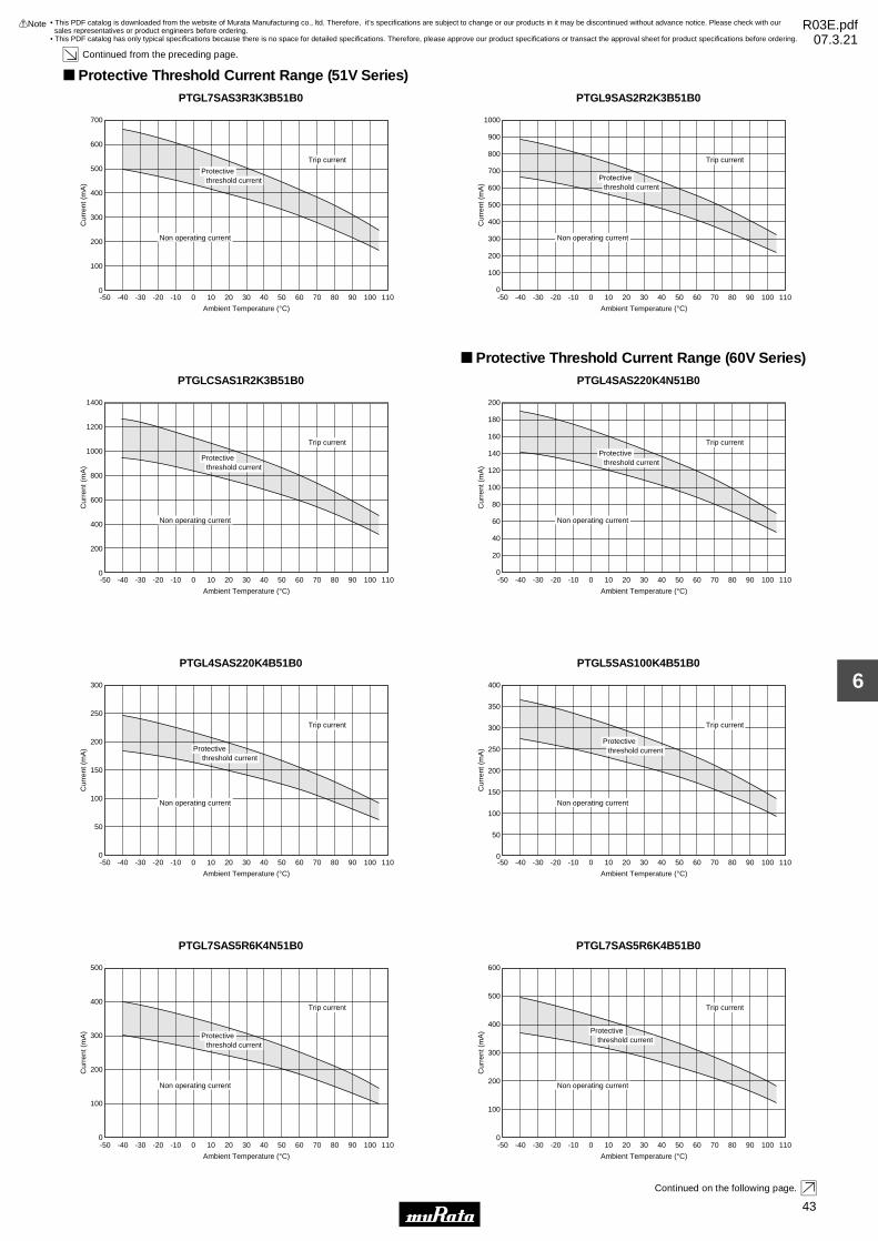
43
6
!Note • Please read rating and !CAUTION (for storage, operating, rating, soldering, mounting and handling) in this catalog to prevent smoking and/or burning, etc.• This catalog has only typical specifications because there is no space for detailed specifications. Therefore, please approve our product specifications or transact the approval sheet for product specifications before ordering.
Continued from the preceding page.
Protective Threshold Current Range (51V Series)PTGL7SAS3R3K3B51B0
700
600
500
400
300
200
100
0-50 -40 -30 -20 -10 0 10 20 30 40 50 60 70 80 90 100 110
Ambient Temperature (°C)
Cur
rent
(m
A)
Protectivethreshold current
Trip current
Non operating current
PTGL9SAS2R2K3B51B0
1000
900
800
700
600
500
400
300
200
100
0-50 -40 -30 -20 -10 0 10 20 30 40 50 60 70 80 90 100 110
Ambient Temperature (°C)
Cur
rent
(m
A)
Protectivethreshold current
Trip current
Non operating current
PTGLCSAS1R2K3B51B0
1400
1200
1000
800
600
400
200
0-50 -40 -30 -20 -10 0 10 20 30 40 50 60 70 80 90 100 110
Ambient Temperature (°C)
Cur
rent
(m
A)
Protectivethreshold current
Trip current
Non operating current
Protective Threshold Current Range (60V Series)PTGL4SAS220K4N51B0
200
180
160
140
120
100
80
60
40
20
0-50 -40 -30 -20 -10 0 10 20 30 40 50 60 70 80 90 100 110
Ambient Temperature (°C)
Cur
rent
(m
A)
Protectivethreshold current
Trip current
Non operating current
PTGL4SAS220K4B51B0
300
250
200
150
100
50
0-50 -40 -30 -20 -10 0 10 20 30 40 50 60 70 80 90 100 110
Ambient Temperature (°C)
Cur
rent
(m
A) Protective
threshold current
Trip current
Non operating current
PTGL5SAS100K4B51B0
400
350
300
250
200
150
100
50
0-50 -40 -30 -20 -10 0 10 20 30 40 50 60 70 80 90 100 110
Ambient Temperature (°C)
Cur
rent
(m
A)
Protectivethreshold current
Trip current
Non operating current
PTGL7SAS5R6K4N51B0
500
400
300
200
100
0-50 -40 -30 -20 -10 0 10 20 30 40 50 60 70 80 90 100 110
Ambient Temperature (°C)
Cur
rent
(m
A)
Protectivethreshold current
Trip current
Non operating current
PTGL7SAS5R6K4B51B0
600
500
400
300
200
100
0-50 -40 -30 -20 -10 0 10 20 30 40 50 60 70 80 90 100 110
Ambient Temperature (°C)
Cur
rent
(m
A) Protective
threshold current
Trip current
Non operating current
Continued on the following page.
• This PDF catalog is downloaded from the website of Murata Manufacturing co., ltd. Therefore, it’s specifications are subject to change or our products in it may be discontinued without advance notice. Please check with our sales representatives or product engineers before ordering.
• This PDF catalog has only typical specifications because there is no space for detailed specifications. Therefore, please approve our product specifications or transact the approval sheet for product specifications before ordering.
!Note R03E.pdf07.3.21

44
6
!Note • Please read rating and !CAUTION (for storage, operating, rating, soldering, mounting and handling) in this catalog to prevent smoking and/or burning, etc.• This catalog has only typical specifications because there is no space for detailed specifications. Therefore, please approve our product specifications or transact the approval sheet for product specifications before ordering.
Continued from the preceding page.
Protective Threshold Current Range (60V Series)PTGL9SAS3R3K4B51B0
800
700
600
500
400
300
200
100
0-50 -40 -30 -20 -10 0 10 20 30 40 50 60 70 80 90 100 110
Ambient Temperature (°C)
Cur
rent
(m
A)
Protectivethreshold current
Trip current
Non operating current
PTGLCSAS2R2K4B51B0
1000
800
600
400
200
0-50 -40 -30 -20 -10 0 10 20 30 40 50 60 70 80 90 100 110
Ambient Temperature (°C)
Cur
rent
(m
A)
Protectivethreshold current
Trip current
Non operating current
Protective Threshold Current Range (140V Series)PTGL4SAS560K6B51B0
180
160
140
120
100
80
60
40
20
0-50 -40 -30 -20 -10 0 10 20 30 40 50 60 70 80 90 100 110
Ambient Temperature (°C)
Cur
rent
(m
A) Protective
threshold current
Trip current
Non operating current
PTGL5SAS270K6B51B0
250
200
150
100
50
0-50 -40 -30 -20 -10 0 10 20 30 40 50 60 70 80 90 100 110
Ambient Temperature (°C)
Cur
rent
(m
A)
Protectivethreshold current
Trip current
Non operating current
PTGL7SAS150K6B51B0
350
300
250
200
150
100
50
0-50 -40 -30 -20 -10 0 10 20 30 40 50 60 70 80 90 100 110
Ambient Temperature (°C)
Cur
rent
(m
A)
Protectivethreshold current
Trip current
Non operating current
PTGL9SAS120K6B51B0
500
400
300
200
100
0-50 -40 -30 -20 -10 0 10 20 30 40 50 60 70 80 90 100 110
Ambient Temperature (°C)
Cur
rent
(m
A) Protective
threshold current
Trip current
Non operating current
PTGL9SAS7R6K6B51B0
600
500
400
300
200
100
0-50 -40 -30 -20 -10 0 10 20 30 40 50 60 70 80 90 100 110
Ambient Temperature (°C)
Cur
rent
(m
A) Protectivethreshold current
Trip current
Non operating current
PTGLCSAS4R7K6B51B0
700
600
500
400
300
200
100
0-50 -40 -30 -20 -10 0 10 20 30 40 50 60 70 80 90 100 110
Ambient Temperature (°C)
Cur
rent
(m
A)
Protectivethreshold current
Trip current
Non operating current
Continued on the following page.
• This PDF catalog is downloaded from the website of Murata Manufacturing co., ltd. Therefore, it’s specifications are subject to change or our products in it may be discontinued without advance notice. Please check with our sales representatives or product engineers before ordering.
• This PDF catalog has only typical specifications because there is no space for detailed specifications. Therefore, please approve our product specifications or transact the approval sheet for product specifications before ordering.
!Note R03E.pdf07.3.21
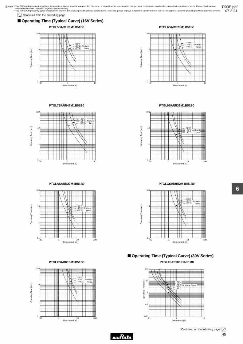
45
6
!Note • Please read rating and !CAUTION (for storage, operating, rating, soldering, mounting and handling) in this catalog to prevent smoking and/or burning, etc.• This catalog has only typical specifications because there is no space for detailed specifications. Therefore, please approve our product specifications or transact the approval sheet for product specifications before ordering.
Continued from the preceding page.
Operating Time (Typical Curve) (16V Series)PTGL5SAR1R0M1B51B0
100
10
1
0.10.1 1 10
Overcurrent (A)
Ope
ratin
g T
ime
(sec
.)
-30°C+25°C+85°C
Ambient Temp.
PTGL6SAR0R8M1B51B0
100
10
1
0.10.1 1 10
Overcurrent (A)
Ope
ratin
g T
ime
(sec
.)
-30°C+25°C+85°C
Ambient Temp.
PTGL7SARR47M1B51B0
100
10
1
0.10.1 1 10
Overcurrent (A)
Ope
ratin
g T
ime
(sec
.)
-30°C+25°C+85°C
Ambient Temp.
PTGL9SARR33M1B51B0
100
10
1
0.10.1 1 10 100
Overcurrent (A)
Ope
ratin
g T
ime
(sec
.)
-30°C+25°C+85°C
Ambient Temp.
PTGLASARR27M1B51B0
100
10
1
0.10.1 1 10 100
Overcurrent (A)
Ope
ratin
g T
ime
(sec
.) -30°C+25°C+85°C
Ambient Temp.
PTGLCSAR0R2M1B51B0
100
10
1
0.10.1 1 10 100
Overcurrent (A)
Ope
ratin
g T
ime
(sec
.)
-30°C+25°C+85°C
Ambient Temp.
PTGLESARR15M1B51B0
100
10
1
0.10.1 1 10 100
Overcurrent (A)
Ope
ratin
g T
ime
(sec
.)
-30°C+25°C+85°C
Ambient Temp.
Operating Time (Typical Curve) (30V Series)PTGL4SAS100K2N51B0
0.01
0.1
1
10
100
0.1 1 10Overcurrent (A)
Ope
ratin
g T
ime
(sec
.)
- 30°C- 10°C 25°C
60°C85°C
Ambient Temp.
Continued on the following page.
• This PDF catalog is downloaded from the website of Murata Manufacturing co., ltd. Therefore, it’s specifications are subject to change or our products in it may be discontinued without advance notice. Please check with our sales representatives or product engineers before ordering.
• This PDF catalog has only typical specifications because there is no space for detailed specifications. Therefore, please approve our product specifications or transact the approval sheet for product specifications before ordering.
!Note R03E.pdf07.3.21
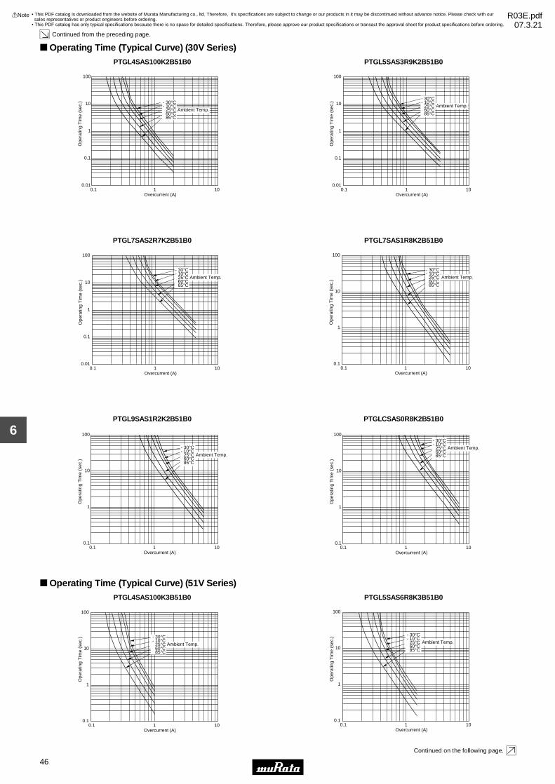
46
6
!Note • Please read rating and !CAUTION (for storage, operating, rating, soldering, mounting and handling) in this catalog to prevent smoking and/or burning, etc.• This catalog has only typical specifications because there is no space for detailed specifications. Therefore, please approve our product specifications or transact the approval sheet for product specifications before ordering.
Continued from the preceding page.
Operating Time (Typical Curve) (30V Series)PTGL4SAS100K2B51B0
0.01
0.1
1
10
100
0.1 1 10Overcurrent (A)
Ope
ratin
g T
ime
(sec
.) - 30°C- 10°C 25°C60°C85°C
Ambient Temp.
PTGL5SAS3R9K2B51B0
0.01
0.1
1
10
100
0.1 1 10Overcurrent (A)
Ope
ratin
g T
ime
(sec
.)
- 30°C- 10°C 25°C60°C85°C
Ambient Temp.
PTGL7SAS2R7K2B51B0
0.01
0.1
1
10
100
0.1 1 10Overcurrent (A)
Ope
ratin
g T
ime
(sec
.)
- 30°C- 10°C 25°C60°C85°C
Ambient Temp.
PTGL7SAS1R8K2B51B0
0.1
1
10
100
0.1 1 10Overcurrent (A)
Ope
ratin
g T
ime
(sec
.)
- 30°C- 10°C 25°C60°C85°C
Ambient Temp.
PTGL9SAS1R2K2B51B0
0.1
1
10
100
0.1 1 10Overcurrent (A)
Ope
ratin
g T
ime
(sec
.)
- 30°C- 10°C 25°C60°C85°C
Ambient Temp.
PTGLCSAS0R8K2B51B0
0.1
1
10
100
0.1 1 10Overcurrent (A)
Ope
ratin
g T
ime
(sec
.)
Ambient Temp.
- 30°C- 10°C 25°C60°C85°C
Operating Time (Typical Curve) (51V Series)PTGL4SAS100K3B51B0
0.1
1
10
100
0.1 1 10Overcurrent (A)
Ope
ratin
g T
ime
(sec
.) - 30°C- 10°C 25°C60°C85°C
Ambient Temp.
PTGL5SAS6R8K3B51B0
0.1
1
10
100
0.1 1 10Overcurrent (A)
Ope
ratin
g T
ime
(sec
.)
- 30°C- 10°C 25°C60°C85°C
Ambient Temp.
Continued on the following page.
• This PDF catalog is downloaded from the website of Murata Manufacturing co., ltd. Therefore, it’s specifications are subject to change or our products in it may be discontinued without advance notice. Please check with our sales representatives or product engineers before ordering.
• This PDF catalog has only typical specifications because there is no space for detailed specifications. Therefore, please approve our product specifications or transact the approval sheet for product specifications before ordering.
!Note R03E.pdf07.3.21

47
6
!Note • Please read rating and !CAUTION (for storage, operating, rating, soldering, mounting and handling) in this catalog to prevent smoking and/or burning, etc.• This catalog has only typical specifications because there is no space for detailed specifications. Therefore, please approve our product specifications or transact the approval sheet for product specifications before ordering.
Continued from the preceding page.
Operating Time (Typical Curve) (51V Series)PTGL7SAS3R3K3B51B0
0.1
1
10
100
0.1 1 10Overcurrent (A)
Ope
ratin
g T
ime
(sec
.)
- 30°C- 10°C 25°C60°C85°C
Ambient Temp.
PTGL9SAS2R2K3B51B0
0.1
1
10
100
0.1 1 10Overcurrent (A)
Ope
ratin
g T
ime
(sec
.)
- 30°C- 10°C 25°C60°C85°C
Ambient Temp.
PTGLCSAS1R2K3B51B0
0.1
1
10
100
0.1 1 10Overcurrent (A)
Ope
ratin
g T
ime
(sec
.)
Ambient Temp.
- 30°C- 10°C 25°C60°C85°C
Operating Time (Typical Curve) (60V Series)PTGL4SAS220K4N51B0
0.01
0.1
1
10
100
0.01 0.1 1Overcurrent (A)
Ope
ratin
g T
ime
(sec
.)
- 30°C- 10°C 25°C60°C85°C
Ambient Temp.
PTGL4SAS220K4B51B0
0.01
0.1
1
10
100
0.1 1 10Overcurrent (A)
Ope
ratin
g T
ime
(sec
.) - 30°C- 10°C 25°C60°C85°C
Ambient Temp.
PTGL5SAS100K4B51B0
0.1
1
10
100
0.1 1 10Overcurrent (A)
Ope
ratin
g T
ime
(sec
.) - 30°C- 10°C 25°C60°C85°C
Ambient Temp.
PTGL7SAS5R6K4N51B0
0.1
1
10
100
0.1 1 10Overcurrent (A)
Ope
ratin
g T
ime
(sec
.) - 30°C- 10°C 25°C60°C85°C
Ambient Temp.
PTGL7SAS5R6K4B51B0
0.1
1
10
100
0.1 1 10Overcurrent (A)
Ope
ratin
g T
ime
(sec
.) - 30°C- 10°C 25°C60°C85°C
Ambient Temp.
Continued on the following page.
• This PDF catalog is downloaded from the website of Murata Manufacturing co., ltd. Therefore, it’s specifications are subject to change or our products in it may be discontinued without advance notice. Please check with our sales representatives or product engineers before ordering.
• This PDF catalog has only typical specifications because there is no space for detailed specifications. Therefore, please approve our product specifications or transact the approval sheet for product specifications before ordering.
!Note R03E.pdf07.3.21

48
6
!Note • Please read rating and !CAUTION (for storage, operating, rating, soldering, mounting and handling) in this catalog to prevent smoking and/or burning, etc.• This catalog has only typical specifications because there is no space for detailed specifications. Therefore, please approve our product specifications or transact the approval sheet for product specifications before ordering.
Continued from the preceding page.
Operating Time (Typical Curve) (60V Series)PTGL9SAS3R3K4B51B0
0.1
1
10
100
0.1 1 10Overcurrent (A)
Ope
ratin
g T
ime
(sec
.) - 30°C- 10°C 25°C60°C85°C
Ambient Temp.
PTGLCSAS2R2K4B51B0
0.1
1
10
100
0.1 1 10Overcurrent (A)
Ope
ratin
g T
ime
(sec
.) - 30°C- 10°C 25°C60°C85°C
Ambient Temp.
Operating Time (Typical Curve) (140V Series)PTGL4SAS560K6B51B0
0.1
1
10
100
0.01 0.1 1Overcurrent (A)
Ope
ratin
g T
ime
(sec
.) Ambient Temp.
- 30°C- 10°C 25°C60°C85°C
PTGL5SAS270K6B51B0
0.1
1
10
100
0.1 1 10Overcurrent (A)
Ope
ratin
g T
ime
(sec
.)
- 30°C- 10°C 25°C60°C85°C
Ambient Temp.
PTGL7SAS150K6B51B0
0.1
1
10
100
0.1 1 10Overcurrent (A)
Ope
ratin
g T
ime
(sec
.)
- 30°C- 10°C 25°C60°C
Ambient Temp.
85°C
PTGL9SAS120K6B51B0
0.1
1
10
100
0.1 1 10Overcurrent (A)
Ope
ratin
g T
ime
(sec
.) Ambient Temp.
- 30°C- 10°C 25°C60°C85°C
PTGL9SAS7R6K6B51B0
0.1
1
10
100
0.1 1 10Overcurrent (A)
Ope
ratin
g T
ime
(sec
.)
- 30°C- 10°C 25°C60°C85°C
Ambient Temp.
PTGLCSAS4R7K6B51B0
0.1
1
10
100
0.1 1 10Overcurrent (A)
Ope
ratin
g T
ime
(sec
.)
- 30°C- 10°C 25°C60°C85°C
Ambient Temp.
• This PDF catalog is downloaded from the website of Murata Manufacturing co., ltd. Therefore, it’s specifications are subject to change or our products in it may be discontinued without advance notice. Please check with our sales representatives or product engineers before ordering.
• This PDF catalog has only typical specifications because there is no space for detailed specifications. Therefore, please approve our product specifications or transact the approval sheet for product specifications before ordering.
!Note R03E.pdf07.3.21

The load is gradually applied to each terminal of POSISTORruntil the force of 4.9N in the axial direction with fixingPOSISTORr's body itself and this load is being kept for 10seconds.
POSISTORr is held so that it is perpendicular to the lead wirewith 2.45N in the axial direction of the lead wire. The lead wireis slowly bent toward 90° and returned; then it is slowly bent inthe opposite direction and returned to original state.
The lead wire of POSISTORr is soaked in a Isopropyl Alcohol(JIS K 8839) solution (about 25wt%) of colophony (JIS K 5902)for 5-10 seconds. And, each lead wire is soaked in molten solder (JIS Z 3282 H60A) at 235±5°C from the bottom to apoint of 2.0-2.5mm for 2±0.5 seconds.
The lead wire of POSISTORr is soaked in molten solder (JIS Z3282 H60A) at 350±10°C from the bottom to a point of 2.0-2.5mm for 3.5±0.5 seconds. After the device is left at room temperature (25°C) for 24±4hours, the resistance is measured.
No. Item Rating Value Method of Examination
No problem
Satisfies ratings(Trip Current, Non-operating Current)
No damage
Lead wire does not come off
Solder is applied around the lead wire covering 3/4or more of the circumference without gap in the axialdirection.
∆R/R25V±15%
-30 to +85°C
Satisfies specification
Operating Temperature
Resistance (R25)
Withstanding Voltage
1
2
3
Protective Threshold Current
Tensile Strength of LeadWire Terminal
Solderability
4
5
Bending Strength of LeadWire Terminal
6
7
Resistance value is measured by applying voltage under1.5Vdc (by a direct current of less than 10mA) at 25°C. (But itmust be measured after maximum voltage is applied 180 seconds and then is left for 2 hours at 25°C.)
We apply AC voltage 110% that of the maximum voltage toPOSISTORr by raising voltage gradually for 180±5 seconds at25°C. (A protective resistor is to be connected in series, andthe inrush current through POSISTORr must be limited belowmaximum rated value.)
Maximum current measured in this examination. Voltage isapplied to POSISTORr in 3 minutes step by step on still air.Stable current is measured at each step.
The temperature range with maximum voltage applied to thePOSISTORr.
At 85±3°C chamber, POSISTORr is applied max. voltage for1.5 hr on and 0.5 hr off. This cycle is repeated for 500±10hours, and after the device is left at room temperature (25°C)for 1 hour, the resistance measurement is performed. (A protective resistance is to be connected in series and theinrush current through POSISTORr must be limited belowmax. rated value.)
Terminal Durability ofSoldering
8
∆R/R25V±20%No damage about marking
POSISTORr is set in an environmental chamber at 40±2°Cand 90% to 95% humidity, for 500±4 hours.And, after the device is left at room temperature (25°C) for 1 hour, the resistance measurement is performed.
Heat Resistant9
∆R/R25V±20%No damage about marking
Resistance to Damp Heat10
16V Series
POSISTORr Lead Type for Overheat Protection Specifications and Test Methods
49
6
!Note • Please read rating and !CAUTION (for storage, operating, rating, soldering, mounting and handling) in this catalog to prevent smoking and/or burning, etc.• This catalog has only typical specifications because there is no space for detailed specifications. Therefore, please approve our product specifications or transact the approval sheet for product specifications before ordering.
• This PDF catalog is downloaded from the website of Murata Manufacturing co., ltd. Therefore, it’s specifications are subject to change or our products in it may be discontinued without advance notice. Please check with our sales representatives or product engineers before ordering.
• This PDF catalog has only typical specifications because there is no space for detailed specifications. Therefore, please approve our product specifications or transact the approval sheet for product specifications before ordering.
!Note R03E.pdf07.3.21

Maximum current measured in this examination. Voltage isapplied to POSISTORr in 3 minutes step by step on still airbased on “Protective Threshold Current Test Conditions”shown in next page. Stable current is measured at each step.
The load is gradually applied to each terminal of POSISTORruntil the force of 4.9N in the axial direction with fixingPOSISTORr's body itself and this load is being kept for 10seconds.
POSISTORr is held so that it is perpendicular to the lead wirewith 2.45N in the axial direction of the lead wire. The lead wireis slowly bent toward 90° and returned; then it is slowly bent inthe opposite direction and returned to original state.
The lead wire of POSISTORr is soaked in a Isopropyl Alcohol(JIS K 8839) solution (about 25wt%) of colophony (JIS K 5902)for 5-10 sec. And, each lead wire is soaked in molten solder(JIS Z 3282 H60A) at 235±5°C from the bottom to a point of2.0-2.5mm for 2±0.5 seconds.
No. Item Rating Value Method of Examination
Satisfies ratings
No problem
Satisfies ratings(Trip Current, Non-operating Current)
No damage
Lead wire does not come off
Solder is applied around the lead wire covering 3/4or more of the circumference without gap in the axialdirection.
-30 to +125°C
-40 to +125°C
Operating Temperature 1
Operating Temperature 2
Resistance (R25)
1
2
3
Withstanding Voltage
Protective Threshold Current
Bending Strength of LeadWire Terminal
4
5
Tensile Strength of LeadWire Terminal
6
7
The temperature range with following voltage applied to thePOSISTORr.<applied voltage>30V and 51V series: max. 16V, 60V series: max. 30V, 140Vseries: max. 140V
Resistance value is measured by applying voltage under1.0Vdc (by a direct current of less than 10mA) at 25°C. (But itmust be measured after it is applied maximum voltage for 180seconds and then is left for 2 hours at 25°C.)
We apply AC voltage 120% that of the maximum voltage toPOSISTORr by raising voltage gradually for 180±5 seconds at25°C. (A protective resistor is to be connected in series, andthe inrush current through POSISTORr must be limited belowmax. rated value.)
The temperature range with maximum voltage applied to thePOSISTORr.
The lead wire of POSISTORr is soaked in molten solder (JIS Z3282 H60A) at 350±10°C from the bottom to a point of 2.0-2.5mm for 3.5±0.5 sec. After the device is left at room temperature (25°C) for 24±4 hours, the resistance is measured.
Solderability8
∆R/R25V±15%
Acceleration: 98m/s2 (10G)Width: 1.5mmVibration: 10-500-10HzVibrate for 11minutes Z 24 cycles in each of 3 mutually perpendicular planes for a total of 13.5 hours.
Terminal Durability ofSoldering
9
∆R/R25V±20%
∆R/R25V±20%
∆R/R25V±20%
∆R/R25V±20%
POSISTORr is set in an environmental chamber at 125±3°Cfor 1000±12 hours. After the device is left at room temperature(25°C) for one hour, the resistance measurement is performed.
Vibration Resistant10
POSISTORr is set in an environmental chamber at -40±3°Cfor 1000±12 hours. After the device is left at room temperature(25°C) for one hour, the resistance measurement is performed.
Heat Resistant11
POSISTORr is set in an environmental chamber at 85±3°Cand 80-85% humidity for 1000±12 hours. After the device is leftat room temperature (25°C) for one hour, the resistance measurement is performed.
Cold Resistant
Resistance to Damp Heat
12
13
Continued on the following page.
30-140V Series
POSISTORr Lead Type for Overheat Protection Specifications and Test Methods
50
6
!Note • Please read rating and !CAUTION (for storage, operating, rating, soldering, mounting and handling) in this catalog to prevent smoking and/or burning, etc.• This catalog has only typical specifications because there is no space for detailed specifications. Therefore, please approve our product specifications or transact the approval sheet for product specifications before ordering.
• This PDF catalog is downloaded from the website of Murata Manufacturing co., ltd. Therefore, it’s specifications are subject to change or our products in it may be discontinued without advance notice. Please check with our sales representatives or product engineers before ordering.
• This PDF catalog has only typical specifications because there is no space for detailed specifications. Therefore, please approve our product specifications or transact the approval sheet for product specifications before ordering.
!Note R03E.pdf07.3.21

25.0
5.0
2.5
1.0
fai 0.9
25.0
25.0
25.0
2.5 2.5
3.0
(in : mm)
D.C POWERSUPPLY
D.V+-
POSISTORr
1ΩDigital Voltmeter
D.V+-
Digital Voltmeter
Continued from the preceding page.
Materials: Phenol Size: 50x50xt1.6mmLand Pattern: Cu land without through hole
(1) Substrate
(3) Measurement circuit
Solder POSISTORr on the substrate, then put the cover (150mm cubed) surround POSISTORr to prevent flow of wind.
(2) Measurement condition
Protective Threshold current test conditions
POSISTORr Lead Type for Overheat Protection Specifications and Test Methods
51
6
!Note • Please read rating and !CAUTION (for storage, operating, rating, soldering, mounting and handling) in this catalog to prevent smoking and/or burning, etc.• This catalog has only typical specifications because there is no space for detailed specifications. Therefore, please approve our product specifications or transact the approval sheet for product specifications before ordering.
• This PDF catalog is downloaded from the website of Murata Manufacturing co., ltd. Therefore, it’s specifications are subject to change or our products in it may be discontinued without advance notice. Please check with our sales representatives or product engineers before ordering.
• This PDF catalog has only typical specifications because there is no space for detailed specifications. Therefore, please approve our product specifications or transact the approval sheet for product specifications before ordering.
!Note R03E.pdf07.3.21

POSISTORr Lead Type for Overheat Protection !Caution/Notice
52
6
!Note • Please read rating and !CAUTION (for storage, operating, rating, soldering, mounting and handling) in this catalog to prevent smoking and/or burning, etc.• This catalog has only typical specifications because there is no space for detailed specifications. Therefore, please approve our product specifications or transact the approval sheet for product specifications before ordering.
!Caution (Storage and Operating Condition)This product is designed for application in an ordinary environment (normal room temperature, humidity and atmospheric pressure). Do not use under the following conditions because all these factors can deteriorate the characteristics or cause product failure and burn-out.1. Corrosive gas or deoxidizing gas (Chlorine gas, Hydrogen sulfide gas, Ammonia gas, Sulfuric acid gas, Nitric oxide gas, etc.)
2. Volatile or flammable gas3. Dusty conditions4. Under vacuum, or under high or low-pressure5. Wet or humid conditions6. Places with salt water, oils, chemical liquids or organic solvents7. Strong vibrations8. Other places where similar hazardous conditions exist
!Caution (Other)Be sure to provide an appropriate fail-safe function on your product to prevent secondary damage that may becaused by the abnormal function or the failure of our product.
Notice (Storage and Operating Condition)To keep solderability of product from declining, following storage condition is recommended.1. Storage condition: Temperature -10 to +40 degrees C Humidity less than 75%RH (not dewing condition)2. Storage term: Use this product within 6 months after delivery by first-in and first-out stocking system.
3. Handling after unpacking: After unpacking, promptly reseal this product or store it in a sealed container with a drying agent.4. Storage place: Do not store this product in corrosive gas (Sulfuric acid, Chlorine, etc.) or in direct sunlight.
Notice (Soldering and Mounting)When the lead of this product is soldered, pay attention as follows to avoid the decline of element characteristics or break-down of the element.1. Use Rosin type flux or non-activated flux 2. Do not dip the body into flux (flux should be coated to lead wire only for soldering).3. Be sure that preheating does not melt the soldering of this product.
Notice (Handling)1. Do not apply an excessive force to the lead. Otherwise, it may cause the junction between lead and element to break, or may crack the element. Therefore, holding the element side lead wire is recommended when lead wire is bent or cut.2. This product does not have waterproof construction. Splashed water may cause failure mode such as decline of characteristics or current leak.
3. When this product is operated, temperature of some areas may be over 100 to 160 degrees C. Be sure that surrounding parts and inserting material can withstand the temperature. If the surrounding part and material are kept under such conditions, they may deteriorate or produce harmful gas (Chlorine gas, Hydrogen sulfide gas, Ammonia gas, Sulfuric acid gas, Nitric oxide gas, etc.). And such harmful gas may deteriorate the element.
• This PDF catalog is downloaded from the website of Murata Manufacturing co., ltd. Therefore, it’s specifications are subject to change or our products in it may be discontinued without advance notice. Please check with our sales representatives or product engineers before ordering.
• This PDF catalog has only typical specifications because there is no space for detailed specifications. Therefore, please approve our product specifications or transact the approval sheet for product specifications before ordering.
!Note R03E.pdf07.3.21

NCP15
NCP18
10000
4000
Part NumberPaper Tape
-
-
Embossed Tape
Quantity (pcs.)
(in mm)
(in mm)
40 min.190-250
Vacant Section
210-250
Top Tape aloneCover Tape alone
Leader Unit
Trailer Unit
Chip-mounting Unit
Direction of Feed
ø178±2.0
ø21.0±0.8
ø13.0±0.5
ø50
min
.
2.0±0.5
10.0±1.52.0±0.5
(1) A tape in a reel contains Leader unit and Trailer unit where
products are not packed. (Please refer to the figure at right.)
(2) The top and base tapes or plastic and cover tape are not
stuck at the first five pitches minimum.
(3) A label should be attached on the reel. (MURATA's part
number, inspection number and quantity should be marked
on the label.)
(4) Taping reels are packed in a package.
1. Dimensions of Reel
2. Taping Method
Tape Carrier Packaging
Minimum Quantity Guide
Continued on the following page.
1
For NTC Thermistors Chip Type Package
53
6
!Note • Please read rating and !CAUTION (for storage, operating, rating, soldering, mounting and handling) in this catalog to prevent smoking and/or burning, etc.• This catalog has only typical specifications because there is no space for detailed specifications. Therefore, please approve our product specifications or transact the approval sheet for product specifications before ordering.
• This PDF catalog is downloaded from the website of Murata Manufacturing co., ltd. Therefore, it’s specifications are subject to change or our products in it may be discontinued without advance notice. Please check with our sales representatives or product engineers before ordering.
• This PDF catalog has only typical specifications because there is no space for detailed specifications. Therefore, please approve our product specifications or transact the approval sheet for product specifications before ordering.
!Note R03E.pdf07.3.21
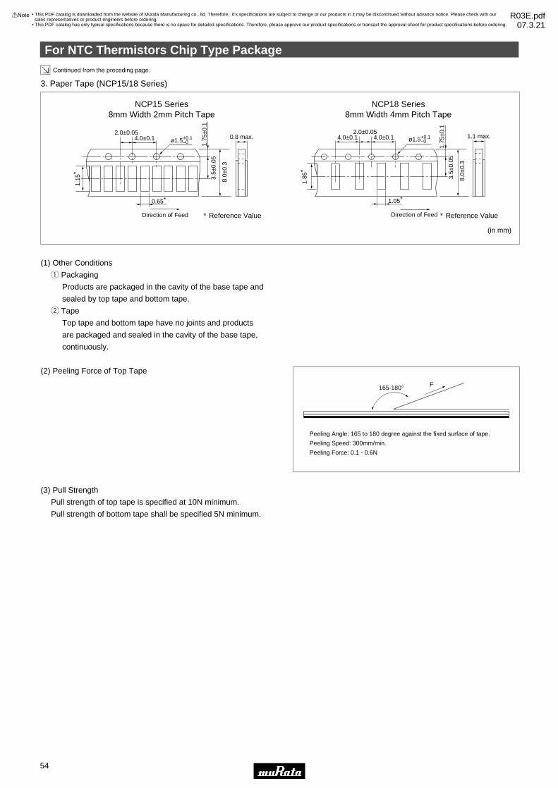
(1) Other Conditions
q Packaging
Products are packaged in the cavity of the base tape and
sealed by top tape and bottom tape.
w Tape
Top tape and bottom tape have no joints and products
are packaged and sealed in the cavity of the base tape,
continuously.
(2) Peeling Force of Top Tape
(3) Pull Strength
Pull strength of top tape is specified at 10N minimum.
Pull strength of bottom tape shall be specified 5N minimum.
3. Paper Tape (NCP15/18 Series)
NCP15 Series8mm Width 2mm Pitch Tape
NCP18 Series8mm Width 4mm Pitch Tape
1.1 max.4.0±0.1 4.0±0.12.0±0.05
ø1.5
1.75
±0.1
3.5±
0.05
8.0±
0.3
Direction of Feed
1.05∗
0.8 max.4.0±0.12.0±0.05
ø1.5
1.75
±0.1
3.5±
0.05
1.15
∗
8.0±
0.3
Direction of Feed
0.65∗
(in mm)
∗ Reference Value∗ Reference Value
165-180° F
Peeling Angle: 165 to 180 degree against the fixed surface of tape.
Peeling Speed: 300mm/min.
Peeling Force: 0.1 - 0.6N
Continued from the preceding page.
1.85
∗
+0.1–0
+0.1–0
2
For NTC Thermistors Chip Type Package
54
6
!Note • Please read rating and !CAUTION (for storage, operating, rating, soldering, mounting and handling) in this catalog to prevent smoking and/or burning, etc.• This catalog has only typical specifications because there is no space for detailed specifications. Therefore, please approve our product specifications or transact the approval sheet for product specifications before ordering.
• This PDF catalog is downloaded from the website of Murata Manufacturing co., ltd. Therefore, it’s specifications are subject to change or our products in it may be discontinued without advance notice. Please check with our sales representatives or product engineers before ordering.
• This PDF catalog has only typical specifications because there is no space for detailed specifications. Therefore, please approve our product specifications or transact the approval sheet for product specifications before ordering.
!Note R03E.pdf07.3.21

For NTC Thermistors Lead Type Package
55
6
!Note • Please read rating and !CAUTION (for storage, operating, rating, soldering, mounting and handling) in this catalog to prevent smoking and/or burning, etc.• This catalog has only typical specifications because there is no space for detailed specifications. Therefore, please approve our product specifications or transact the approval sheet for product specifications before ordering.
Item Code Dimension (mm)
Pitch of Component
Pitch of Sprocket Hole
Lead Spacing
Length from Hole Center to Component Center
Length from Hole Center to Lead
Body Diameter
Deviation along Tape, Left or Right Defect
Carrier Tape Width
Position of Sprocket Hole
Lead Distance between Reference and Bottom Planes
Height of Component
Protrusion Length
Diameter of Sprocket Hole
Lead Diameter
Total Tape Thickness
Total Thickness, Tape and Lead Wire
Deviation across Tape
Portion to Cut in Case of Defect
Hole Down Tape Width
Hole Down Tape Position
Coating Extension on Lead
Body Thickness
P
P0
F
P2
P1
D
∆S
W
W1
H0
H2
I
D0
d
t1
t2
∆h1, ∆h2
L
W0
W2
e
T
12.7
12.7±0.3
5.0+0.8/–0.2
6.35±1.3
3.85±0.8
3.5 max.
0±2.0
18.0±0.5
9.0±0.5
16.0±1.0
4.0 max.
+0.5 to –1.0
4.0±0.1
0.50±0.03
0.6±0.3
1.6 max.
1.0 max.
11.0+0/–2.0
11.0 min.
1.5±1.5
Up to the crimp point
2.6 max.
(in mm)
Minimum Quantity Guide
Taping Dimension (NTSS_N6A0 Series)
P2
P0I
L
P ∆S
H2
W2
W0
H0W1
W
t2 t1
∆h2 ∆h1
T
øD0
D
P1 ød
F
e
Part NumberTaping (Ammo Pack)
Minimum Quantity (pcs.)
Bulk*
NTSS 3000 100
* This quantity differs from actual delivery quantity in a package.
• This PDF catalog is downloaded from the website of Murata Manufacturing co., ltd. Therefore, it’s specifications are subject to change or our products in it may be discontinued without advance notice. Please check with our sales representatives or product engineers before ordering.
• This PDF catalog has only typical specifications because there is no space for detailed specifications. Therefore, please approve our product specifications or transact the approval sheet for product specifications before ordering.
!Note R03E.pdf07.3.21

*1.05 *Reference Value
1.1 max.1.75
±0.1
4.0±0.12.0±0.1
4.0±0.1
3.5±
0.05
8.0±
0.3
Direction feed
(1.8
5)
(in mm)
(in mm)
ø13.0±0.2
ø21.0±0.8
9.0
ø60
ø180W0Y1.5
W1.
0Y
0
W1.0Y0
2.0±0.5
13.0±1.0
Reel Dimensions
Part NumberQuantity (pcs.)
Paper Tape Embossed Tape
PR*18_RB
PR*21_RA
PR*21_RK
4000
-
-
-
4000
3000
1.45±0.1Direction feed
1.75
±0.1
4.0±0.1 4.0±0.12.0±0.1
3.5±
0.05
8.0±
0.3
ø1.5W0.1Y0
2.25
±0.1
ø1.0±0.1
1.30±0.05
0.25±0.05
1.45Direction feed
1.75
±0.1
4.0±0.1 4.0±0.12.0±0.1
3.5±
0.05
8.0±
0.3
ø1.0W0.3Y0
ø1.5W0.1Y0
2.25
1.1
0.2
PR*18_RB Series: Paper Tape
PR*21_RA Series: Embossed Tape PR*21_RK Series: Embossed Tape
! Minimum Quantity Guide
! Tape Dimensions
! Reel Dimensions
ø1.5W0.1Y0
For POSISTORr Chip Type Package
56
6
!Note • Please read rating and !CAUTION (for storage, operating, rating, soldering, mounting and handling) in this catalog to prevent smoking and/or burning, etc.• This catalog has only typical specifications because there is no space for detailed specifications. Therefore, please approve our product specifications or transact the approval sheet for product specifications before ordering.
• This PDF catalog is downloaded from the website of Murata Manufacturing co., ltd. Therefore, it’s specifications are subject to change or our products in it may be discontinued without advance notice. Please check with our sales representatives or product engineers before ordering.
• This PDF catalog has only typical specifications because there is no space for detailed specifications. Therefore, please approve our product specifications or transact the approval sheet for product specifications before ordering.
!Note R03E.pdf07.3.21

For POSISTORr Lead Type Package
57
6
!Note • Please read rating and !CAUTION (for storage, operating, rating, soldering, mounting and handling) in this catalog to prevent smoking and/or burning, etc.• This catalog has only typical specifications because there is no space for detailed specifications. Therefore, please approve our product specifications or transact the approval sheet for product specifications before ordering.
Pitch of Component
Pitch of Sprocket Hole
Lead Spacing
Length from Hole Center to Lead
Length from Hole Center to Component Center
Body Diameter
Body Thickness
Deviation along Tape, Left or Right Defect
Carrier Tape Width
Position of Sprocket Hole
Lead Distance between Reference and Bottom Planes
Protrusion Length
Diameter of Sprocket Hole
Lead Diameter
Total Tape Thickness
Total Thickness of Tape and Lead Wire
Deviation across Tape
Portion to cut in Case of Defect
Hold Down Tape Width
Hold Down Tape Position
Coating Extension on Lead
P
P0
F
P1
P2
D
T
∆S
W
W1
H0
H2
I
D0
d
t1
t2
∆h1, ∆h2
L
W0
W2
e
12.7
12.7±0.3
5.0
3.85±0.8
6.35±1.3
Please see in Ratings
Please see in Ratings
±1.5
18.0±0.5
16.0±1.0
6.0 max.
W0.5 — Y1.0
4.0±0.2
Please see in Ratings
0.6±0.3
2.0 max.
1.5 max.
11.0 min.
4.0 max.
Up to the center of crimp
Tolerance is determined by ∆S.
Deviation in the feeding direction
Including the inclination caused by lead bending
Deviation of tape width
CodeItem Dimensions (mm) Note
+0.8–0.3
9.0+0.5–0.75
11.0+0–2.0
W0
W2
W
W1
H0
H2
∆h2∆h1
e
∆SP2 P
D
P1
P0
F d
l øD0
L
t2
t1
T
Minimum Quantity Guide
c Taping Dimension (PTGL_A0 Series)
Part NumberTaping (Ammo Pack)
Minimum Quantity (pcs.)
Bulk*
PTGL (16V Series)
PTGL (30 to 140V Series)
2000 100
1500 100
* This quantity differs from actual delivery quantity in a package.
• This PDF catalog is downloaded from the website of Murata Manufacturing co., ltd. Therefore, it’s specifications are subject to change or our products in it may be discontinued without advance notice. Please check with our sales representatives or product engineers before ordering.
• This PDF catalog has only typical specifications because there is no space for detailed specifications. Therefore, please approve our product specifications or transact the approval sheet for product specifications before ordering.
!Note R03E.pdf07.3.21

Note:1. Export Control
<For customers outside Japan>No muRata products should be used or sold, through any channels, for use in the design, development, production, utilization, maintenance or operation of, orotherwise contribution to (1) any weapons (Weapons of Mass Destruction (nuclear, chemical or biological weapons or missiles) or conventional weapons) or (2)goods or systems specially designed or intended for military end-use or utilization by military end-users.<For customers in Japan>For products which are controlled items subject to the “Foreign Exchange and Foreign Trade Law” of Japan, the export license specified by the law is requiredfor export.
2. Please contact our sales representatives or product engineers before using the products in this catalog for the applications listed below, which require especiallyhigh reliability for the prevention of defects which might directly damage a third party's life, body or property, or when one of our products is intended for use inapplications other than those specified in this catalog.q Aircraft equipment w Aerospace equipmente Undersea equipment r Power plant equipmentt Medical equipment y Transportation equipment (vehicles, trains, ships, etc.)u Traffic signal equipment i Disaster prevention / crime prevention equipmento Data-processing equipment !0 Application of similar complexity and/or reliability requirements to the applications listed above
3. Product specifications in this catalog are as of January 2007. They are subject to change or our products in it may be discontinued without advance notice.Please check with our sales representatives or product engineers before ordering. If there are any questions, please contact our sales representatives orproduct engineers.
4. Please read rating and CAUTION (for storage, operating, rating, soldering, mounting and handling) in this catalog to prevent smoking and/or burning, etc.
5. This catalog has only typical specifications because there is no space for detailed specifications. Therefore, please approve our product specifications ortransact the approval sheet for product specifications before ordering.
6. Please note that unless otherwise specified, we shall assume no responsibility whatsoever for any conflict or dispute that may occur in connection with the effectof our and/or a third party's intellectual property rights and other related rights in consideration of your use of our products and/or information described orcontained in our catalogs. In this connection, no representation shall be made to the effect that any third parties are authorized to use the rights mentionedabove under licenses without our consent.
7. No ozone depleting substances (ODS) under the Montreal Protocol are used in our manufacturing process.
International Division3-29-12, Shibuya, Shibuya-ku, Tokyo 150-0002, Japan Phone: 81-3-5469-6123 Fax: 81-3-5469-6155 E-mail: [email protected]
Head Office1-10-1, Higashi Kotari, Nagaokakyo-shi, Kyoto 617-8555, JapanPhone: 81-75-951-9111
http://www.murata.com/
• This PDF catalog is downloaded from the website of Murata Manufacturing co., ltd. Therefore, it’s specifications are subject to change or our products in it may be discontinued without advance notice. Please check with our sales representatives or product engineers before ordering.
• This PDF catalog has only typical specifications because there is no space for detailed specifications. Therefore, please approve our product specifications or transact the approval sheet for product specifications before ordering.
!Note R03E.pdf07.3.21


