Olivet Nazarene UniversityDigital Commons @ Olivet
Honors Program Projects Honors Program
5-1-2011
Obstacle Avoidance Subsystem for anAutonomous RobotKirstie KingOlivet Nazarene University, [email protected]
This Article is brought to you for free and open access by the Honors Program at Digital Commons @ Olivet. It has been accepted for inclusion inHonors Program Projects by an authorized administrator of Digital Commons @ Olivet. For more information, please contact [email protected].
Recommended CitationKing, Kirstie, "Obstacle Avoidance Subsystem for an Autonomous Robot" (2011). Honors Program Projects. Paper 7.http://digitalcommons.olivet.edu/honr_proj/7
OBSTACLE AVOIDANCESUBSYSTEM FOR AN AUTONOMOUS ROBOT
By
Kirstie King
Honors CapstoneProject
Submitted to the Faculty of
Olivet Nazarene University
for partial fulfillment of the requirements for
GRADUATION WITH UNIVERSITY HONORS
May, 2011
BACHELOR OF SCIENCE
in
Computer Engineering
D . Lc>crr1 I
3\.,-_"' E. ~ ~ ~ \ \ - ; < l - ~ ~ · · ~ ~ · ~ ~ ~ J Honors Council Chair (printed) Signature
Honors Counci!Meffi ertprinted) Signature
f/<'lr, 17 ;<o !/ Date

i
ACKNOWLEDGEMENTS
I would like to acknowledge all of the help and mentoring I have received from
Professor Joseph Makarewicz in understanding how to start designing the software
architecture for an autonomous system. I would also like to mention Dr. Larry Vail, for
agreeing to be my official Honors mentor, even though this project wasn’t part of his
department. I would also like to thank all of the seven other teammates I have had
during the course of this project. Being part of this team was an integral part of
completing this project.
FOREWORD
This is a subproject from within a larger engineering team working together to
design and implement an autonomous ground vehicle. The report is a compilation of
the work completed for the team’s Design Proposal and Design Report that is applicable
to the development of the obstacle avoidance subsystem.
ii
TABLE OF CONTENTS
ACKNOWLEDGEMENTS ........................................................................................................ i
FOREWORD .......................................................................................................................... i
LIST OF TABLES .................................................................................................................... iv
LIST OF FIGURES ................................................................................................................... v
INTRODUCTION ................................................................................................................... 1
Problem Definition .................................................................................................. 1
Background ............................................................................................................. 2
Sponsoring Organizations ........................................................................... 2
IGVC Events ................................................................................................. 3
Problem History .......................................................................................... 4
REVIEW OF LITERATURE ...................................................................................................... 5
METHODS ............................................................................................................................ 7
System Requirements and Constraints ................................................................... 7
Minimum Design Goals ............................................................................... 7
Functional Requirements ............................................................................ 7
Design Alternatives ................................................................................................. 8
Selection of Design Alternatives ........................................................................... 10
RESULTS............................................................................................................................. 12
iii
Hardware Connection ........................................................................................... 12
Overall Software Architecture .............................................................................. 20
Collision Avoidance Subsystem Software Interface ............................................. 23
DISCUSSION ....................................................................................................................... 25
Design Verification ................................................................................................ 25
Conclusion ............................................................................................................. 26
REFERENCES ...................................................................................................................... 27
APPENDICES ...................................................................................................................... 30
Appendix A: Acronyms .......................................................................................... 30
Appendix B: Technology/Software Review ........................................................... 30
Laser Range Finder and Vision Technology .............................................. 30
Python ....................................................................................................... 31
Appendix C: Installing SICK Laser Rangefinder Configuration Software ............... 31
Appendix D: Code Listing: Sensor Interface for Laser Rangefinder ...................... 32
Appendix E: Code Listing: Obstacle Class.............................................................. 34
Appendix F: Test run output of LMS Sensor Interface Code ................................ 34
iv
LIST OF TABLES
Table 1: Changes to Serial Connection ............................................................................. 16
Table 3: System State from Status Lights ......................................................................... 17
Table 4: Telegram Structure [15] ...................................................................................... 18
Table 5: Example of a Complete Telegram (standard devices) [15] ................................. 18
Table 6: Laser Rangefinder Configuration Order [15] ...................................................... 20
v
LIST OF FIGURES
Figure 1: Power and Serial Communication Cables [10]................................................... 12
Figure 2: Power Supply Plug [10] ...................................................................................... 13
Figure 3: Layout of the Serial Connection Plug [10] ......................................................... 13
Figure 4: Wire Crossing Between TxD and RxD [10] ......................................................... 14
Figure 5: RS-232 Pin Out ................................................................................................... 16
Figure 6: Laser Rangefinder Status Lights [10] ................................................................. 17
Figure 7: General Telegram Data Format ......................................................................... 18
Figure 8: Software Architecture ........................................................................................ 21
Figure 9: Laser Rangefinder Screenshot ........................................................................... 25
vi
ABSTRACT
This research project details the design and implementation of the Obstacle
Avoidance Subsystem for the Tigertron autonomous robot. This subsystem is designed
to function as a smaller part of the whole Software Architecture and has the purpose of
detecting, through use of a Laser Rangefinder, obstacles in the vehicle’s environment.
Once the hardware is set up and configured, the Tigertron’s central software control
architecture requests data from the Laser Rangefinder through a serial communication
channel. This data is converted into objects that represent obstacles in the form of
polar coordinates. These objects are stored in a container so the central control
architecture can determine the best route to avoid these obstacles while still navigating
to route waypoints.
Keywords
Autonomous, Behavior Layer, Coordination and Planning, Intelligent Ground Vehicle
Competition, Laser Management System, Laser Rangefinder, Obstacle Avoidance
System, Python Programming Language, Real-time System, RS-232, Serial
Communication, SICK LMS, World Modeling
1
INTRODUCTION
It is a misconception with some that autonomous is synonymous with artificially
intelligent. Autonomous is derived from the ancient Greek word αὐτόνομος
(autonomos), which is made up of the words αὐτο (auto), meaning "self," and νόμος
(nomos), meaning "law." Putting these two words together provides the semantic
meaning: "one who gives oneself his own law." In robotics autonomy merely means
independence of control—that a robot can perform specific tasks without continuous
human guidance. Autonomy implies that the entity’s decisions are constrained. An
artificially intelligent entity is one that perceives its surroundings and takes actions to
maximize its chances of success. Therefore an artificially intelligent entity is
autonomous, but an autonomous entity isn’t necessarily artificially intelligent.
The Intelligent Ground Vehicle (IGVC) is a competition where participating teams
each develop an autonomous vehicle. These vehicles may also possess artificially
intelligent traits, though this is not a requirement. Teams are encouraged to be
innovative to help drive new developments in the field of autonomous robotics.
Problem Definition
The Tigertron team as a whole is focused on the creation of an autonomous
vehicle with the goal of entering the IGVC in a future year. This vehicle needs to
conform to the regulations of that competition. An autonomous vehicle is self-
contained and self-controlled. This individual project is focused on the development of
2
the software architecture, specifically the research and development of an obstacle
avoidance subsystem.
An obstacle avoidance subsystem is a type of “perception system” (Typiak, 2008,
p. 246). According to Typiak (2008), the central issue for developing an effective overall
robot system is to implement an efficient system capable of “recognizing the vehicles
surrounding*s+” and “detecting and localizing obstacles and other *hazardous+ objects”
[16, p. 247]. In a design report by Bergh, Kennedy, Matthies, and Johnson (n.d.) they
suggest that using a laser rangefinder set at a particular elevation angle is useful for
“obstacle detection, map building, and position estimation” *1, p. 3+. This project
focuses on interfacing with a Laser Rangefinder to identify obstacles.
Background
Sponsoring Organizations
The sponsor organization for the Tigertron project is Olivet Nazarene University’s
Department of Engineering. Olivet is a Christian liberal arts university that was founded
in 1907. The university had its first engineering graduates in 1990 and the Accreditation
Board for Engineering and Technology (ABET) accredited the engineering program in
2000. Currently, the department consists of mechanical, electrical, computer, and
geological engineering majors. The faculty contacts for the project are from the
electrical and mechanical engineering majors.

3
The IGVC is sponsored by several different organizations including:
Department of Defense (DoD)
U.S. Army Tank Automotive Research Development and Engineering Center
(TARDEC)
United States Military Academy (USMA) at West Point
Oakland University (OU)
Association for Unmanned Vehicle System International (AUVSI)
Society of Automotive Engineers (SAE)
Theta Tau Professional Engineering Fraternity
Joint Ground Robotics Enterprise (JGRE)
Joint Architecture for Unmanned Systems (JAUS)
Applied Research Laboratories (ARL)
General Motors (GM)
Communications Systems International (CSI) Wireless.
IGVC Events
There are two parts main parts of the competition. The first challenge involves
following a marked lane to a destination while avoiding obstacles. The second challenge
includes inputting GPS coordinates defining waypoints and a final destination, and
navigating to each of these waypoints while avoiding obstacles. The Tigertron team is
focusing on developing basic functionalities necessary for both of these challenges.

4
Problem History
ONU’s sponsorship of the Tigertron project began in the fall of 2006 when the
first proposal was written. This team created the original design, which was not
completed in time to be brought to competition. There have been several different
teams who have worked on the project since the original team. None of these teams
were ever able to produce an autonomous vehicle capable of entering the IGVC
competition. Eventually, the project was set aside. In 2008 a new team restarted the
Tigertron project. This was the beginning of a two-year project to produce the current
version of the Tigertron project. The teams that have worked on the Tigertron project
since 2008 have been focused on the electrical and software systems of the robot.
During the Fall 2009 and Spring 2010 semesters, the team worked at redesigning the
electronics, programming the laser rangefinder, and recoding the software for the
robot. This year the previous year’s coding was discarded because the decision was
made to switch programming languages to Python.
In 2011, the 19th Annual Intelligent Ground Vehicle Competition will be held at
Oakland University in Rochester, Michigan. In 1993 only five teams entered into the
competition. In 2010, forty-eight teams participated in the competition.
5
REVIEW OF LITERATURE
There is no set way for robots to observe their environments. There are many
possible implementations, most of which are specific to their application. In general,
robotic “vision” systems seem to use a laser rangefinder, a camera, or both. In the
article “A Compact, Low Power Two-Axis Scanning Laser Rangefinder for Mobile
Robotics” Bergh, Kennedy, Matthies et al explore using a laser rangefinder with an
autonomous robot. Their two main applications of using a laser rangefinder are
environment mapping and collision avoidance [1]. Another article—“Use of Laser
Rangefinder to Detecting in Surroundings of Mobile Robot the Obstacles”—describes
the use of a laser rangefinder as part of a mobile robot’s navigation system. Though the
robot is remote controlled, it is designed with an autonomous backup system, making it
still applicable to this project. This system also uses the laser rangefinder for obstacle
detection and map drawing [16]. These two articles confirm the use of a laser
rangefinder for obstacle detection within robotic navigation systems, which is the focus
of this project.
Another set of articles covered the uses of cameras for environment detection.
Choi and Lee in “Application of Moving Windows Technique to Autonomous Vehicle
Navigation” developed a “moving window” scheme is used to detect lanes, obstacles,
and passageways from a high-quality digital video camera image [14]. Because this
method requires high-performance efficient real-time data processing software it is not
plausible to use directly for this project. Besides being used to detect obstacles a
camera can also be useful for a competition where the robot is trying to stay between
6
two (specifically colored) lines. For example in the article “Vision-Guided Robotics: A
Next-Generation Balancing Robot” Sander describes the implementation of a vision-
guided robot that can track a dark line [12]. Another article by Iovine covers a similar
idea, but instead of following a line he constructs a robot that follows a specific color
[8]. There is enough work within this area to constitute a separate research subproject
for the Tigertron team.
An article that was integral for the development of the software architecture
design, which includes the obstacle avoidance system software, is “A Solution for
Integrating Map Building and Self Localization Strategies in Mobile Robotics.” In this
article Burguera, González, and Oliver discuss the experimental combination of two
main navigation control architectures: reactive and deliberative. Reactive architectures
have a direct line of communication between sensors and the robot’s actuators.
Deliberative architectures use sensor input to build an internal world model. The robot
uses this model to plan future actions, and then executes them. The research team is
working on developing a layered Hybrid Control Architecture to reap the benefits of
both reactive and deliberative architectures [2]. This architecture model was used as
the basis for the Tigertron’s software architecture.
7
METHODS
This section goes over the design process for the overall Software Architecture
design for the Tigertron Control System and the design process specifically for the
Collision Avoidance Subsystem. Note: The hardware setup of the Laser Rangefinder did
not require any design because there was already a prescribed method of setup detailed
in the SICK LMS Technical Description [10].
System Requirements and Constraints
Minimum Design Goals
The main software design goal is to create the base architecture for the
Tigertron. The architecture must be modular and cohesive, and allow for easy
integration of new modules.
The Collision Avoidance Subsystem must be designed to function as a module
within the larger software control system. The Collision Avoidance Subsystem must act
as the interface for the control system to the LMS hardware.
Functional Requirements
The purpose of the Tigertron Software Control System is to control the robot’s
navigation. Specifically it must keep track of where the robot is, where it is going, and
how it is going to get there. To achieve this purpose the control system must (1) take in
data about its environment. In order to navigate in a real and unpredictable
environment the vehicle must be able to determine its surroundings. The control
system must then (2) interpret environmental data. This means that once data has been
8
collected the control system must analyze it and transform it into a format that it can
manipulate. After the data has been interpreted the control system must (3) make
directional decisions. Using the data it has gathered, the control system must be able to
communicate directions to the motor control system. These directions must allow the
robot to both: journey to waypoints and a final destination, and avoid obstacles along
the way. Finally, the system must (4) function effectively as a real-time system. This
means the control system must be able to respond to its environment and make
directional decisions while operating.
The collision avoidance subsystem must be able to integrate into the central
control system and be able to (1) detect physical obstacles, (2) find the distance to and
relative position of these obstacles, (3) determine how to most efficiently avoid
detected obstacles, (4) communicate any temporary route alterations.
Design Alternatives
There were two areas with design alternatives for the software architecture: the
selection of a programming language, and the main control structure design. The main
design alternative for the obstacle avoidance system was the implementation of
telegram communication.
Key requirements for selecting the programming language included: small
language learning curve, syntax simplicity, and the existence of all necessary external
libraries. Java is the language that the majority of the Computer Engineering students
know, but it is not taught within the curriculum of the mechanical and electrical

9
engineering disciplines. The team needed to choose a language other engineering
majors and future participants could use and learn quickly. Syntax simplicity means how
easily is the code to read and write. Having simple syntax means that there aren’t
difficult data type manipulations and that common method calls, such as print, should
not require multiple method calls. The language chosen by the team must have the
external libraries that allow the team to connect to and manipulate integrated pieces of
hardware. Without these libraries the team would have to write the functionality
contained in these libraries to access the hardware from scratch.
The key requirements for selecting the main control structure design include:
ease of implementation, ability to work with complex systems, modularity, and
efficiency with computationally intensive systems. Ease of implementation refers to
how simple the architecture is to design and implement as a real system. Ability to work
with complex systems means that the control structure will work with a large program
and a large software design. Modularity refers to the ability of the design to easily add
or remove components without creating a failure in the software. A computationally
intensive system is a system that does long and labor intensive calculations. These
calculations take processor power and time, which can cause certain features to run
slowly or not at all. This is not acceptable in a real-time system.
The key requirements for choosing an implementation of telegram
communication are: efficiency and probability of successful serial communication.
Efficiency refers to how well the communication is tailored to the software architecture
rather than to another project. Probability of successful serial communication refers to
10
how difficult it will be to guarantee that the software is communicating properly with
the hardware via a serial connection.
Selection of Design Alternatives
The initial design decision for the software was which programming language
should be used to implement the system. The main options were Java and Python.
Previous teams used Java to design the control system. Using Java would allow
integration of their code into our new system. The main decision to use Python is due
to its simplicity. Python is an object-oriented scripting language and is an easier
language to understand for beginning programmers. This project integrates team
members from Mechanical Engineering and Electrical Engineering, not just Computer
Engineering, which means that current and future team members are not always
experienced programmers. Having a simpler language will make it easier for all team
members to work with the programming environment. Python also offers many pre-
developed libraries that integrate the technologies we are using, such as the Laser
Rangefinder, web cameras, and I2C Communication with the motor controllers.
There are two options for the overall control structure. The first is to have a
control loop that will go through the entire navigation process (starting with reading the
sensors and ending with sending a directional command to the motors) and then
continuously loop back to the beginning of this process. This process is simple to
implement and is effective for small systems. This method will not be effective,
however, if the navigation process becomes too complex. This system is a real time

11
system; if it takes too long to get from the beginning of the navigation process (reading
sensors) to the end (communicating with the motors) the robot is liable to not respond
fast enough to its environment. A better, but more complex way to design the overall
control structure is to split it into threads. Threads will allow the separate subsystems
to simulate simultaneous operation. Each thread will have its own processing loop and
will update the data that it has control over. This design is much more complex to
implement, but is a much more robust and efficient way to design the system, which is
why it was chosen for the final design.
There are two main alternatives for the implementation of telegram
communication. The first option is to program the telegram communication from
scratch. The second is to use a library developed by an outside source. Programming
the telegram protocol from scratch meant that the code will be very efficient and easier
to follow because it will be implemented specifically for this project. Using a library
developed for another project results in including extraneous functionalities. It is also a
difficult process to make the external library compatible with the rest of the software.
The main problem with developing the telegram communication is that serial
communication is very difficult to debug. This would also force the development of a
larger amount of code. Using a fully developed external library provides a better chance
of having successful serial communication with the Laser Rangefinder. Having
successful serial communication is highly necessary for this project so an external library
will be used.
12
RESULTS
This section reviews the final implemented designs used for the Hardware
Connection to the Laser Rangefinder, the overall Software Architecture, and the
Collision Avoidance Subsystem Software Interface to the Laser Rangefinder.
Hardware Connection
Before the Laser Rangefinder can be used in the system the hardware must be
properly connected and configured. The Laser Rangefinder must be connected to a
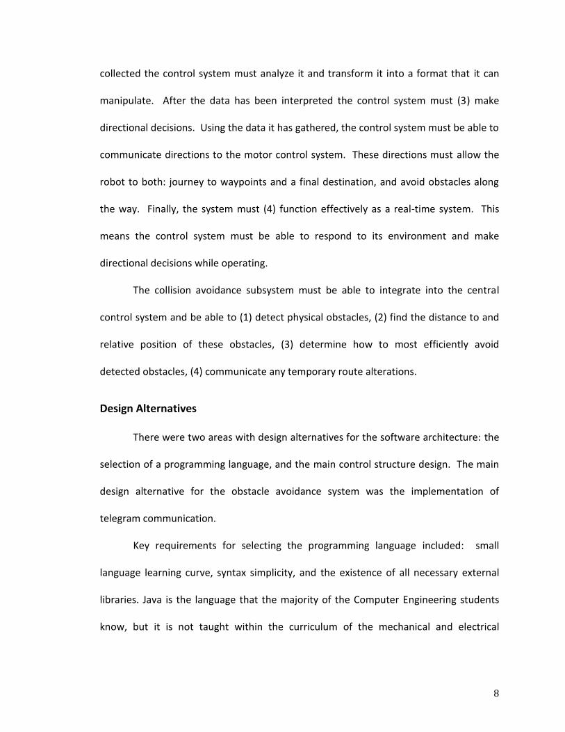
power source and to an RS-232 COM port (on the laptop). The Laser Rangefinder has
two connector cables for these purposes (See Figure 1).
Figure 1: Power and Serial Communication Cables [10]
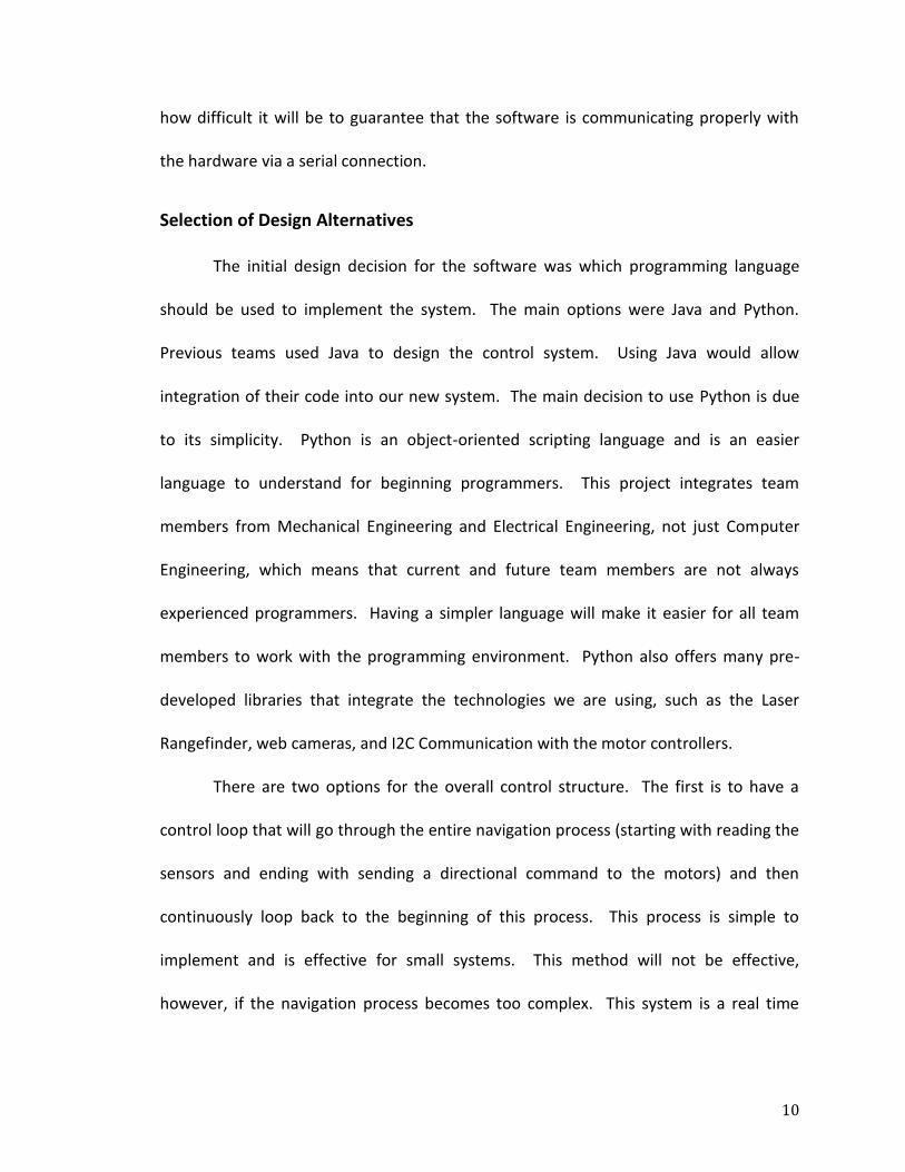
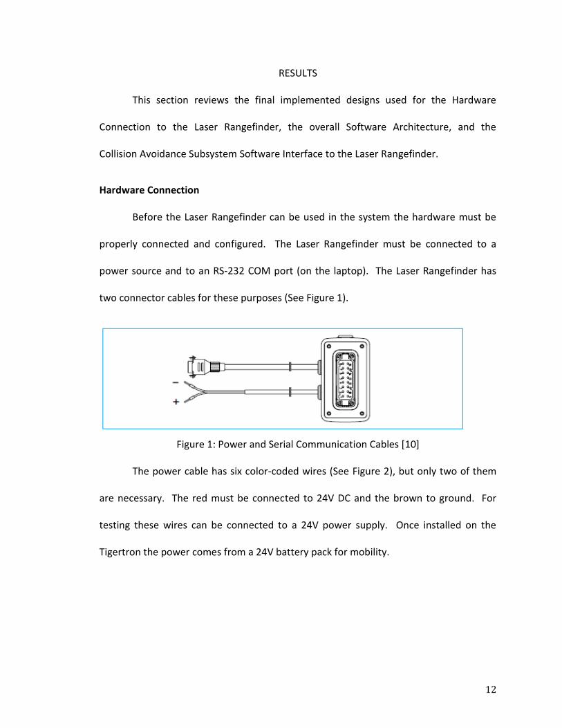
The power cable has six color-coded wires (See Figure 2), but only two of them
are necessary. The red must be connected to 24V DC and the brown to ground. For
testing these wires can be connected to a 24V power supply. Once installed on the
Tigertron the power comes from a 24V battery pack for mobility.
13
Figure 2: Power Supply Plug [10]
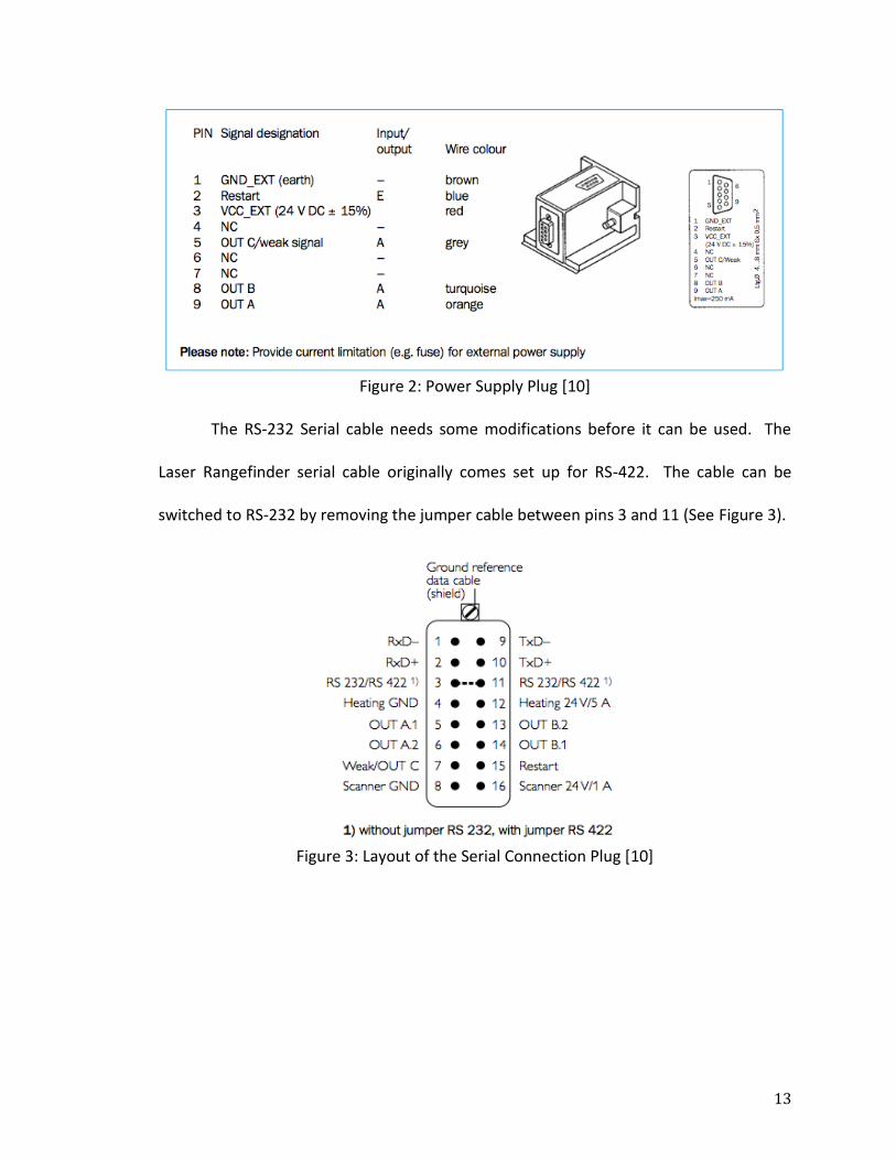
The RS-232 Serial cable needs some modifications before it can be used. The
Laser Rangefinder serial cable originally comes set up for RS-422. The cable can be
switched to RS-232 by removing the jumper cable between pins 3 and 11 (See Figure 3).
Figure 3: Layout of the Serial Connection Plug [10]
14
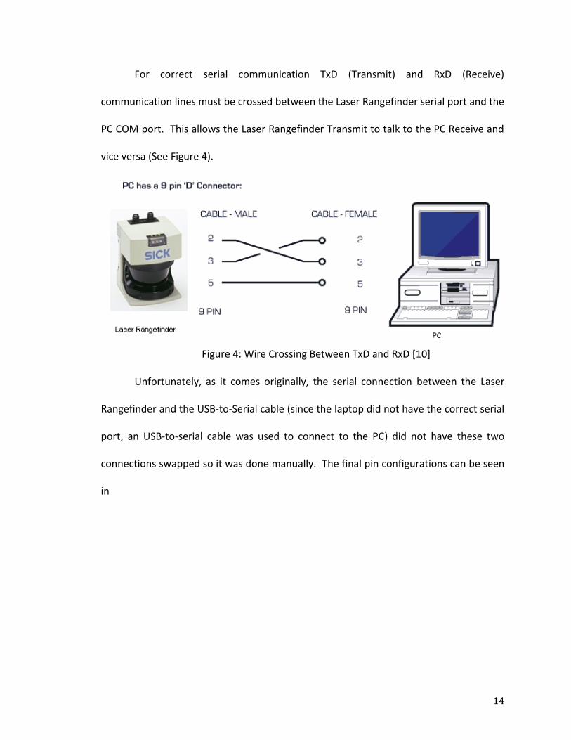
For correct serial communication TxD (Transmit) and RxD (Receive)
communication lines must be crossed between the Laser Rangefinder serial port and the
PC COM port. This allows the Laser Rangefinder Transmit to talk to the PC Receive and
vice versa (See Figure 4).
Figure 4: Wire Crossing Between TxD and RxD [10]
Unfortunately, as it comes originally, the serial connection between the Laser
Rangefinder and the USB-to-Serial cable (since the laptop did not have the correct serial
port, an USB-to-serial cable was used to connect to the PC) did not have these two
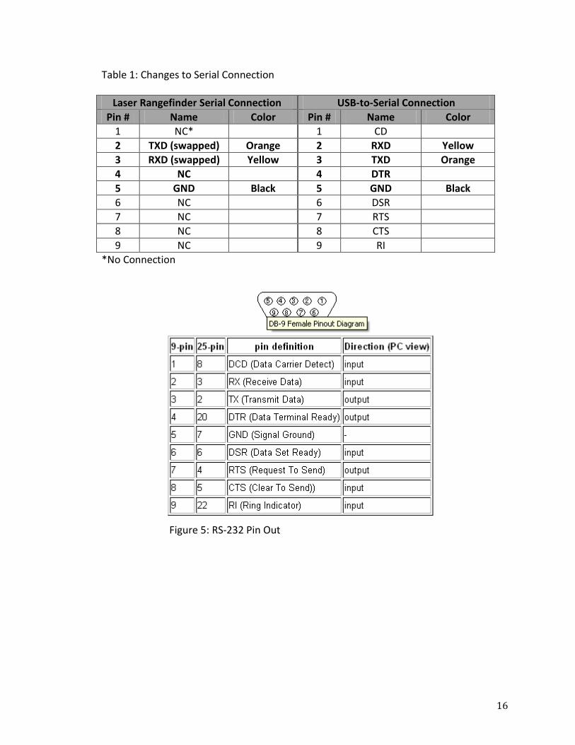
connections swapped so it was done manually. The final pin configurations can be seen
in

15
Table 1. The important pin connections are in bold. Figure 5 gives the physical locations
of each pin.
16
Table 1: Changes to Serial Connection
Laser Rangefinder Serial Connection USB-to-Serial Connection
Pin # Name Color Pin # Name Color
1 NC* 1 CD
2 TXD (swapped) Orange 2 RXD Yellow
3 RXD (swapped) Yellow 3 TXD Orange
4 NC 4 DTR
5 GND Black 5 GND Black
6 NC 6 DSR
7 NC 7 RTS
8 NC 8 CTS
9 NC 9 RI
*No Connection
Figure 5: RS-232 Pin Out
17
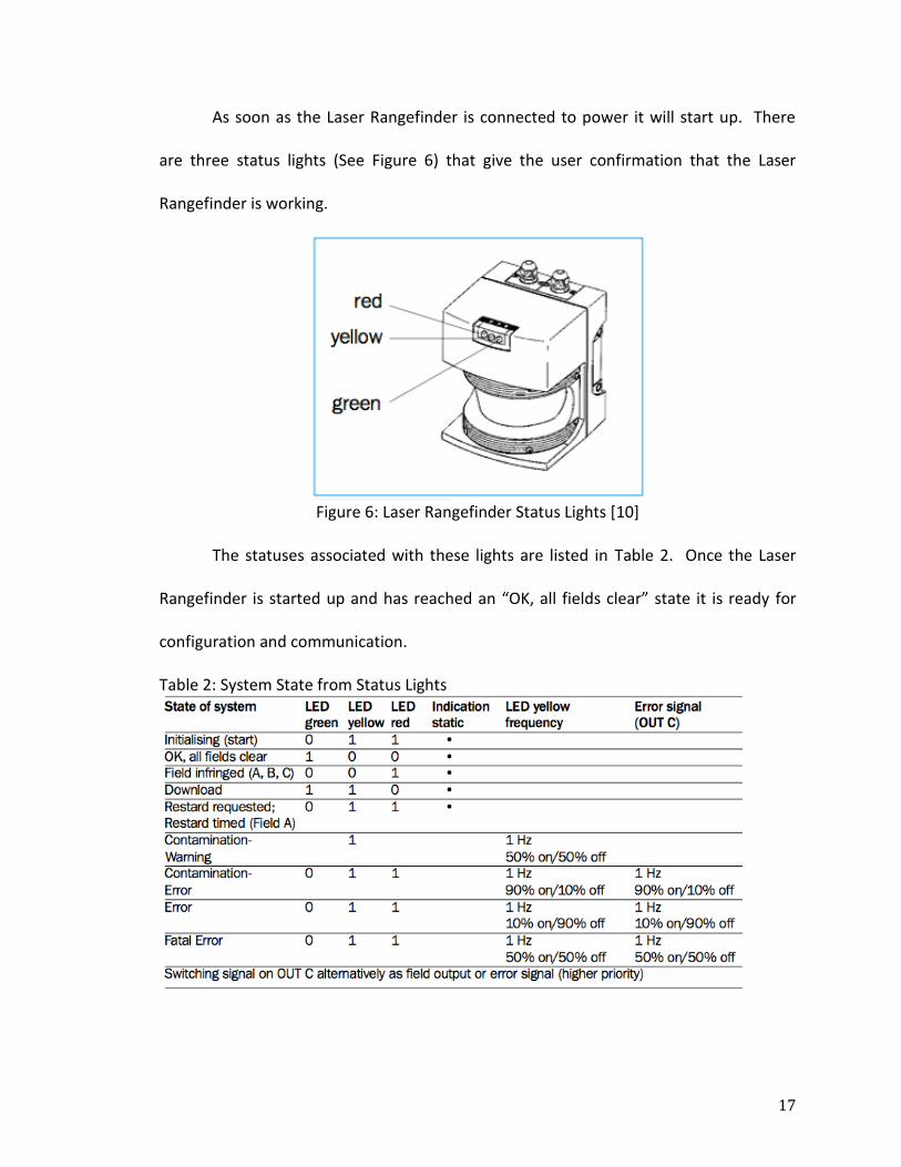
As soon as the Laser Rangefinder is connected to power it will start up. There
are three status lights (See Figure 6) that give the user confirmation that the Laser
Rangefinder is working.
Figure 6: Laser Rangefinder Status Lights [10]
The statuses associated with these lights are listed in Table 2. Once the Laser
Rangefinder is started up and has reached an “OK, all fields clear” state it is ready for
configuration and communication.
Table 2: System State from Status Lights
18
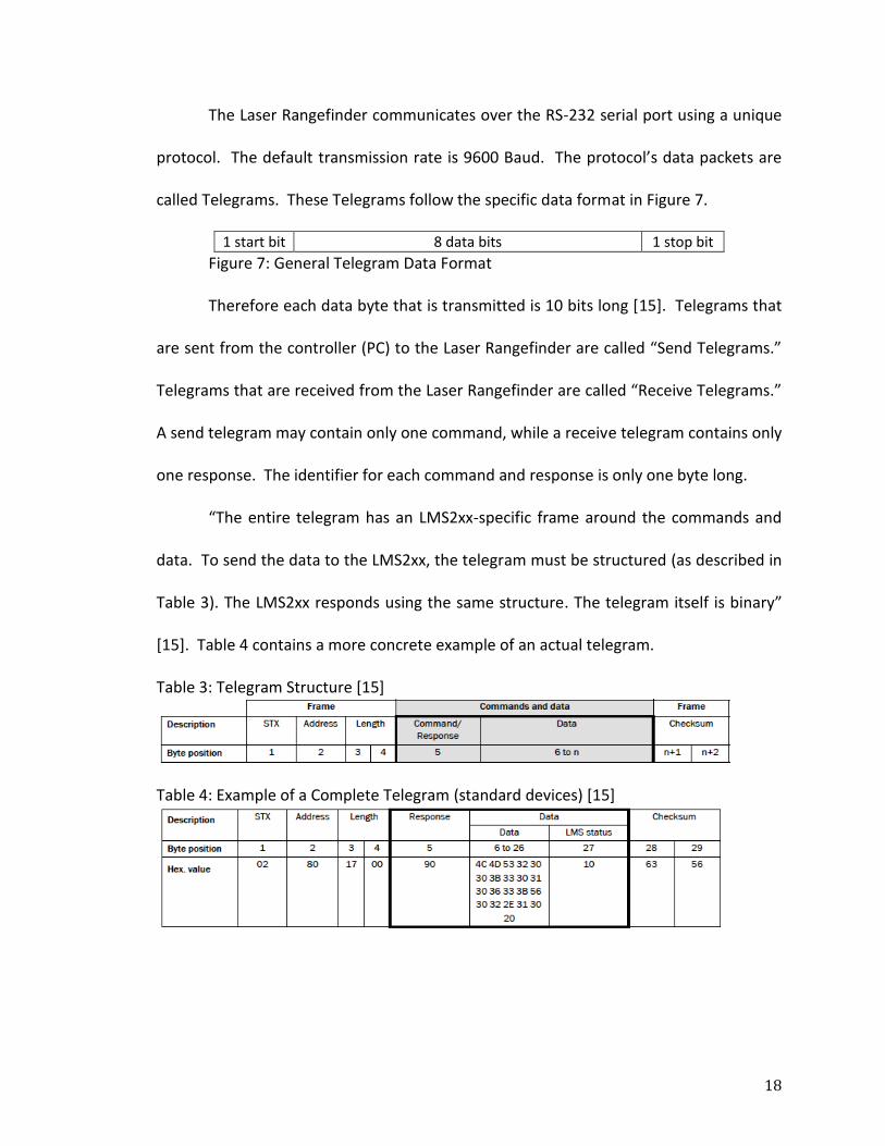
The Laser Rangefinder communicates over the RS-232 serial port using a unique
protocol. The default transmission rate is 9600 Baud. The protocol’s data packets are
called Telegrams. These Telegrams follow the specific data format in Figure 7.
1 start bit 8 data bits 1 stop bit
Figure 7: General Telegram Data Format
Therefore each data byte that is transmitted is 10 bits long [15]. Telegrams that
are sent from the controller (PC) to the Laser Rangefinder are called “Send Telegrams.”
Telegrams that are received from the Laser Rangefinder are called “Receive Telegrams.”
A send telegram may contain only one command, while a receive telegram contains only
one response. The identifier for each command and response is only one byte long.
“The entire telegram has an LMS2xx-specific frame around the commands and
data. To send the data to the LMS2xx, the telegram must be structured (as described in
Table 3). The LMS2xx responds using the same structure. The telegram itself is binary”
[15]. Table 4 contains a more concrete example of an actual telegram.
Table 3: Telegram Structure [15]
Table 4: Example of a Complete Telegram (standard devices) [15]
19
When a command (send) telegram is sent to the Laser Rangefinder it will receive
two response telegrams. The first is either an “Acknowledge” (ACK) or “Not
Acknowledge” (NAK) telegram. An “Acknowledge” telegram specifies the telegram
received was correctly defined. A “Not Acknowledge” telegram specifies that an
incorrect telegram was received and that no further response to that telegram will be
sent. Once a telegram has been acknowledged its corresponding response telegram will
be sent. Each command has a specifically defined response telegram. This response
telegram will also contain any requested data.
The sent data comes in the form of a series of bytes representing distances.
These distances are measured in angular steps that depend on the resolution (for
example every 0.5˚ from 0˚ to 180˚). Each consecutive byte is the measurement for the
next angle in the sequence. This means that the angle is not sent with the data and
must be inferred.
Before any data can be read from the Laser Rangefinder a configuration must be
sent. The configuration tells the Laser Rangefinder how to read data and can change its
operating mode. This can be done either with the provided configuration software
(instructions are listed in LMS Operating Instructions [11]) or programmatically using the
proper telegrams (See Table 5 for the proper order and types of telegrams for
configuration).

20
Table 5: Laser Rangefinder Configuration Order [15]
Overall Software Architecture
The current design will be completed in iterations. The goal of the first iteration
is the development of a functioning system that adheres to the minimum design goals.
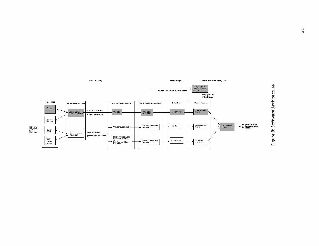
The first iteration is shaded in grey in Figure 8. Additional iterations will add complexity
and functionality to the system. The current system is modular in design. This
modularity will facilitate modifications to the first iteration. This project specifically is
focused on the development of the first part of the shaded iteration. This covers getting
data from the Laser Rangefinder and converting the data into objects in a World
Modeling Container.
2
1
Figu
re 8
: So
ftw
are
Arc
hit
ectu
re
Input GPS Waypoints""" Destination
Sensor c lass
WorldModelling
Sensor Interfaceclass World ModdelingObjects
BehaviOf Layer
AnalyzeContainersto selectmode
World Modeling Containers Behaviors
Coordinationand PlanningLayer
Output DirectionalCommandto Motor Controllers

22
The software architecture design is derived and modified from an architecture
presented in a research paper written by Antoni Burguera, Yolanda González, and
Gabriel Oliver of the Department of Mathematics and Computer Science at the
University of the Balearic Islands [2]. This architecture consists of three main layers:
World Modeling, Behavior, and Coordination and Planning.
The World Modeling Layer focuses on gathering and interpreting sensor data.
Each sensor will have its own class that communicates with the sensor hardware. These
classes will be children of the Sensor class. A Sensor Interface class will interact with the
Sensor classes. Each Sensor Interface will first request data from the sensor and then
will analyze the data. Data analysis will consist of converting the raw sensor data into its
corresponding World Modeling objects. For example, data from the Laser Rangefinder
and Camera will be converted into Obstacle objects. As a final step these objects will be
collected into containers (such as a list or array). Other layers will only be allowed to
access only these containers for World Modeling data (i.e. obstacles and robot position).
The Behavior Layer defines specific robotic behaviors. “Each of these behaviors
is in charge of a single and well-defined control task” [2, p. 6]. In the Tigertron
Architecture each specific behavior will analyze the contents of the World Modeling
Containers and then devise a directional vector for the robot that corresponds with that
behavior’s goal. For example the “Go To” Behavior will determine the vector to the next
geographical waypoint, while the “Avoid Obstacles” Behavior will determine vectors
pointing in the opposite direction from any detected obstacles. Obstacles in close
proximity will result in larger vector magnitudes in order to give these obstacles priority.
23
The Coordination and Planning Layer is the bridge between the software control
system and the motor control system. This layer decides how to prioritize each
Behavior. This layer will function like a state machine where each state is a defined
navigation mode. The current navigation mode will be determined from the contents of
the World Modeling Containers. The current navigation mode will be used to weight
each set of vectors that were produced by the Behavior Layer. Then these vectors will
be summed up into a final vector that will be sent as a directional command to the
motor control system.
Collision Avoidance Subsystem Software Interface
Once the Laser Rangefinder has been connected to the PC and been configured it
must be controlled programmatically so that it can interact with the rest of the
Tigertron Control Architecture.
The Laser Rangefinder code runs as its own thread so that it can run in pseudo-
parallel with the main control thread, navigation thread, and any other sensor threads
that will be introduced in the future. Threads are being used because they are a good
way to implement a real-time system so that the system can react to many different
inputs (from sensor data and navigation controls) at the same time.
The thread begins by scanning for the Laser Rangefinder on COMM ports one
through thirty. If an LMS is not found in these ports the program outputs a warning.
Once a LMS has been found the thread instantiates a sicklms object (from the sicklms
external library).
24
Once a connection has been established the thread enters a continuous data
retrieval loop. The methods provided by the sicklms module (Python class) manage all
of the telegram communication with the LMS. Using the sicklms object, the thread
requests data from the Laser Rangefinder. This data is received as a numpy array (an
external library for a special type of Python array). The thread then converts the
elements of the array into obstacle objects and stores them in a container. On each
loop the Obstacles container will be updated with the most current data from the Laser
Rangefinder. The objects in this container will be analyzed to interpret the location of
obstacles in the vicinity of the robot. When the system is shut down the connection
with the Laser Rangefinder must be properly closed. Not properly closing the
connection causes problems with future connections that can only be solved by
disconnecting and reconnecting the LMS serial cable.

25
DISCUSSION
In order to evaluate the implemented design it must be verified. First, the
hardware connection from the SICK Laser Rangefinder to the laptop must be verified.
Second, the software interface to the LMS must be tested.
Design Verification
Communication was established between Laser Rangefinder and control laptop
through RS-232 serial communication. The configuration software can output a
graphical representation of measured data, but cannot be used to output specific
values. This can be verified by the example screenshot in Figure 9.
Figure 9: Laser Rangefinder Screenshot
26
The Laser Rangefinder Software Interface was verified using a test run of the
software. The Laser Rangefinder was connected using the USB-to-Serial connection,
which acted as a COM port. The configuration was sent to the LMS using the provided
configuration software. Then the Python software interface was run. Output went to
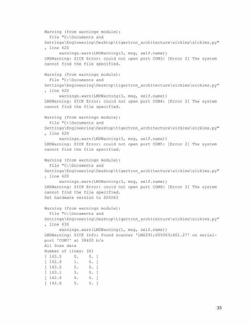
the Python Shell Console. This output is listed in Appendix F: Test run output of LMS
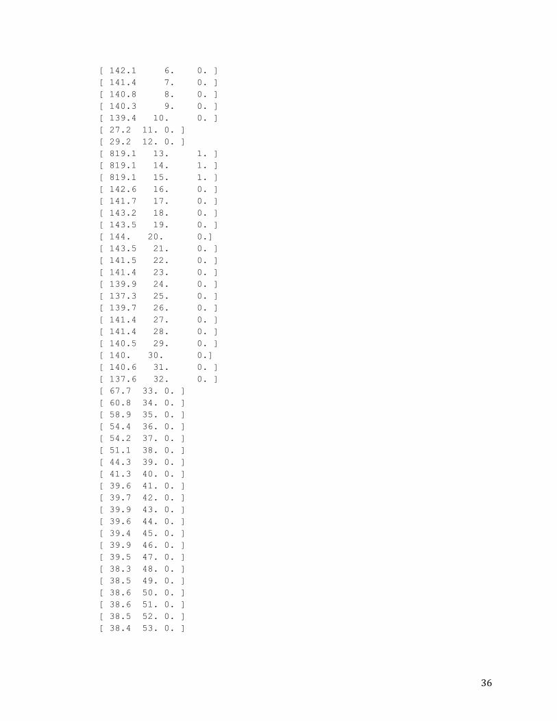
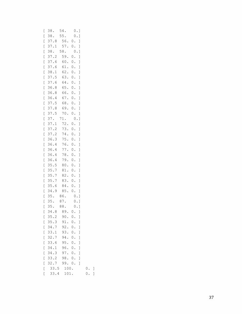
Sensor Interface Code. The output of the test run demonstrated that the software was
correctly able to connect to the LMS, and request and receive data points.
Conclusion
The obstacle avoidance subsystem is written as two stand-alone Python modules
(see Appendix D: Code Listing: Sensor Interface for Laser Rangefinder and Appendix E:
Code Listing: Obstacle Class) and therefore can be integrated into the rest of the central
control system once it is developed. The system detects obstacles by getting data from
the Laser Rangefinder. Once this data is acquired it is converted into Obstacle objects,
which store the data as polar coordinates. These coordinates contain the distance to
the nearest obstacle at incrementing angles of the Laser Rangefinder’s scan. These
objects are stored in a container so that they have more global access. The system does
not yet determine how to avoid obstacles and does not calculate route alterations.
These requirements are part of the Behavior layer and Coordination & Planning layer
and will be further developed by future Tigertron teams.
27
REFERENCES
[1] Bergh, C., Kennedy, B., Matthies, L., & Johnson, A., (n.d.). A Compact, Low Power
Two-Axis Scanning Laser Rangefinder For Mobile Robots. Pasadena, CA: Jet
Propulsion Laboratory, California Institute of Technology.
*2+ Buguera, A., Gonzáles, Y., & Oliver, G., “A Solution for Integrating Map Building and
Self Localization Strategies in Mobile Robotics”, International Journal of
Intelligent Systems, Vol. 20, pp. 499-521, 2005.
*3+ Catlett, A., White, B., “Senior Design Project Proposal for Tigertron Control System”,
December 2009.
*4+ DeBoer, J., King, K., Perkusich, M., et al. “Senior Design Project Proposal for
Tigertron Control System”, December 2010.
*5+ Ibrahim, R., Wald, A., Morehouse, J., Makarewicz, J., Hayes, I., “Senior Design
Proposal for Intelligent Ground Vehicle Competition – TigerTron”, December
2006.
[6] Ibrahim, R., Wald, A., Morehouse, J., Makarewicz, J., Hayes, I., “Senior Design Report
for Intelligent Ground Vehicle Competition – TigerTron”, May 2007.
*7+ “IGVC – Intelligent Ground Vehicle Competition.” Internet: Intelligent Ground Vehicle
Competition, http://www.igvc.org, accessed November 1, 2010.
[8] Iovine, J., (2009, May). C-BOT (Object Tracking). SERVO, 48-54.
28
[9] Jung, B., & Sukhatme, S. (2001). Tracking Multiple Moving Targets using a Camera
and Laser Rangefinder (IRIS-01-397). Los Angeles, CA: Robotic Embedded
Systems Laboratory, Robotics Research Laboratory, Department of Computer
Science, University of Southern California.
[10] LMS 200 / LMS 211 / LMS 220 / LMS 221 / LMS 291 Laser Measurement Systems,
Technical Description, SICK AG, 2003.
[11] LMSIBS Configuration Software for LMS2xx/LMI400 Version 4.1, Operating
Instructions, SICK AG, 2006.
[12] Sander, H. (2009). Vision-Guided Robotics A Next-Generation Balancing Robot.
Circuit Cellar, 224, 22-29.
[13] SICK (2006). LMS200/211/221/291 Laser Measurement Systems TECHNICAL
DESCRIPTION. Waldkirch, Germany.
*14+ Sug Yug Choi and Jang Myung Lee, “Applications of Moving Windows Technique to
Autonomous Vehicle Navigation,” Image and Vision Computing, vol. 24 no. 2, pp.
120-130, 2006.
[15] Telegrams for Configuring and Operating the LMS2xx Laser Measurement Systems,
Telegram Listing, SICK AG, 2006.
[16] Typiak, A., (2008, June). Use of Laser Rangefinder to Detecting in Surroundings of
Mobile Robot the Obstacles. Paper presented at the 25th International
Symposium on Automation and Robotics in Construction, Institute of Internet
and Intelligent Technologies, Vilnius Gediminas Technical University, Vilnius,
Lithuania.
29
*16+ Upchurch, B., Catlett, A. “Senior Design Report for Redesign of Tigertron Control
System”, May 2009.
*17+ “US Patent 6,975,923 B2.” Internet: Autonomous Vehicle Guidance on or near
Airports, http://www.uspto.gov, accessed December 1, 2000.
*18+ “US Patent 7,066,291.” Internet: Robot System, http://www.uspto.gov, accessed
December 1, 2009.
*19+ White, B., Perkusich, M., King, K. “Senior Design Report for Tigertron Navigation
Control System”, May 2010.
30
APPENDICES
Appendix A: Acronyms
ABET Accreditation Board for Engineering and Technology
ASME American Society of Mechanical Engineers
CS Computer Science
DoD Department of Defense
EE Electrical Engineering
GPS Global Positioning System
IEEE Institute of Electrical and Electronics Engineers
IGVC Intelligent Ground Vehicle Competition
LMS Laser Management System (Laser Rangefinder)
ME Mechanical Engineering
ONU Olivet Nazarene University
SAE Society of Automotive Engineers
Appendix B: Technology/Software Review
Laser Range Finder and Vision Technology
A SICK Laser Range Finder (LMS) is used to determine location of obstacles. The
laser range finder measures reflection and delay of feedback to calculate distance from
an object. There are plans to add a web camera as an additional vision sensor for color
and shape recognition.
31
Python
Python is a dynamic programming language that is used in a wide variety of
application domains. Python is often compared to Tcl, Perl, Ruby, Scheme, and Java. Its
key distinguishing features include:
Very clear, readable syntax
Strong introspection capabilities
Intuitive object orientation
Natural expression of procedural code
Full modularity, and supporting hierarchical packages
Exception-based error handling
Very high level dynamic data types
Extensive standard libraries and third party modules for virtually every task
Extensions and modules easily written in C or C++
Embeddable within applications as a scripting interface
Appendix C: Installing SICK Laser Rangefinder Configuration Software
1. The LMS2xx Laser Measurement Systems Configuration Software (LMSIBS v5.20)
is included on a CD-ROM with the Laser Rangefinder
2. Place the CD in the CD drive and open the “CD LMS2xx Version Q393” folder
3. Open the LMSIBS User Software_Benutzersoftware V5.20 folder
4. Run the Install.exe file
32
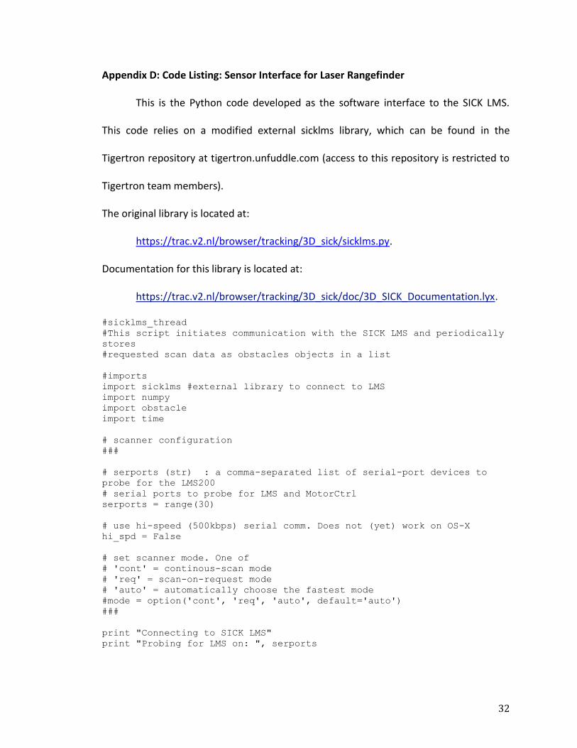
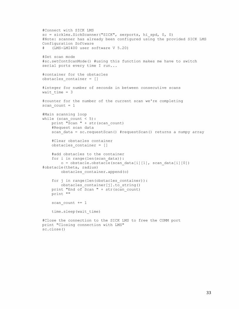
Appendix D: Code Listing: Sensor Interface for Laser Rangefinder
This is the Python code developed as the software interface to the SICK LMS.
This code relies on a modified external sicklms library, which can be found in the
Tigertron repository at tigertron.unfuddle.com (access to this repository is restricted to
Tigertron team members).
The original library is located at:
https://trac.v2.nl/browser/tracking/3D_sick/sicklms.py.
Documentation for this library is located at:
https://trac.v2.nl/browser/tracking/3D_sick/doc/3D_SICK_Documentation.lyx.
#sicklms_thread
#This script initiates communication with the SICK LMS and periodically
stores
#requested scan data as obstacles objects in a list
#imports
import sicklms #external library to connect to LMS
import numpy
import obstacle
import time
# scanner configuration
###
# serports (str) : a comma-separated list of serial-port devices to
probe for the LMS200
# serial ports to probe for LMS and MotorCtrl
serports = range(30)
# use hi-speed (500kbps) serial comm. Does not (yet) work on OS-X
hi_spd = False
# set scanner mode. One of
# 'cont' = continous-scan mode
# 'req' = scan-on-request mode
# 'auto' = automatically choose the fastest mode
#mode = option('cont', 'req', 'auto', default='auto')
###
print "Connecting to SICK LMS"
print "Probing for LMS on: ", serports
33
#Connect with SICK LMS
sc = sicklms.SickScanner("SICK", serports, hi_spd, 0, 0)
#Note: scanner has already been configured using the provided SICK LMS
Configuration Software
# (LMS-LMI400 user software V 5.20)
#Set scan mode
#sc.setContScanMode() #using this function makes me have to switch
serial ports every time I run...
#container for the obstacles
obstacles_container = []
#integer for number of seconds in between consecutive scans
wait_time = 3
#counter for the number of the current scan we're completing
scan_count = 1
#Main scanning loop
while (scan_count < 5):
print "Scan " + str(scan_count)
#Request scan data
scan_data = sc.requestScan() #requestScan() returns a numpy array
#Clear obstacles container
obstacles_container = []
#add obstacles to the container
for i in range(len(scan_data)):
o = obstacle.obstacle(scan_data[i][1], scan_data[i][0])
#obstacle(theta, radius)
obstacles_container.append(o)
for j in range(len(obstacles_container)):
obstacles_container[j].to_string()
print "End of Scan " + str(scan_count)
print ""
scan_count += 1
time.sleep(wait_time)
#Close the connection to the SICK LMS to free the COMM port
print "Closing connection with LMS"
sc.close()
34
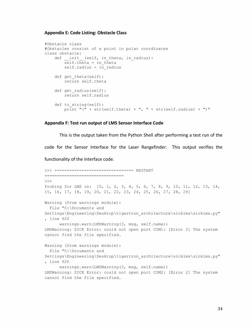
Appendix E: Code Listing: Obstacle Class
#Obstacle class
#Obstacles consist of a point in polar coordinates
class obstacle:
def __init__(self, in_theta, in_radius):
self.theta = in_theta
self.radius = in_radius
def get_theta(self):
return self.theta
def get_radius(self):
return self.radius
def to_string(self):
print "(" + str(self.theta) + ", " + str(self.radius) + ")"
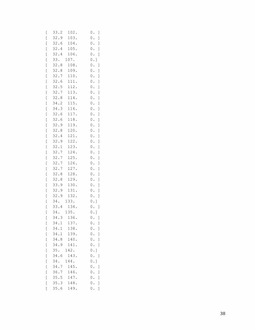
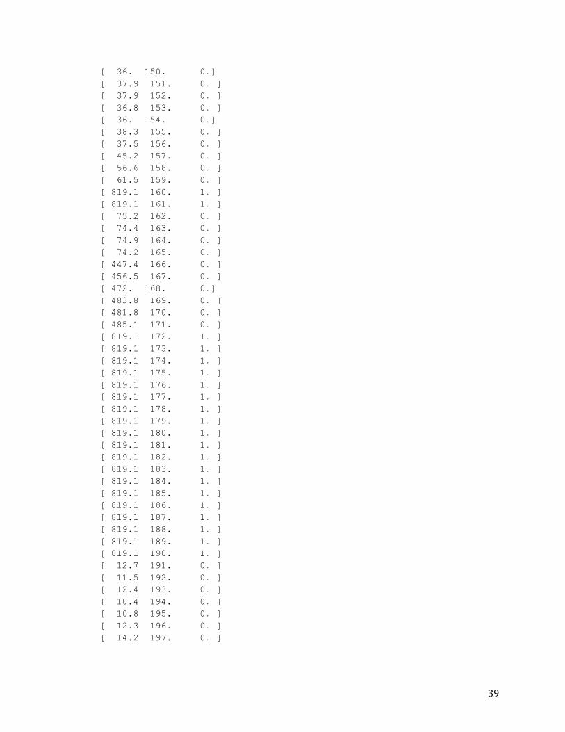
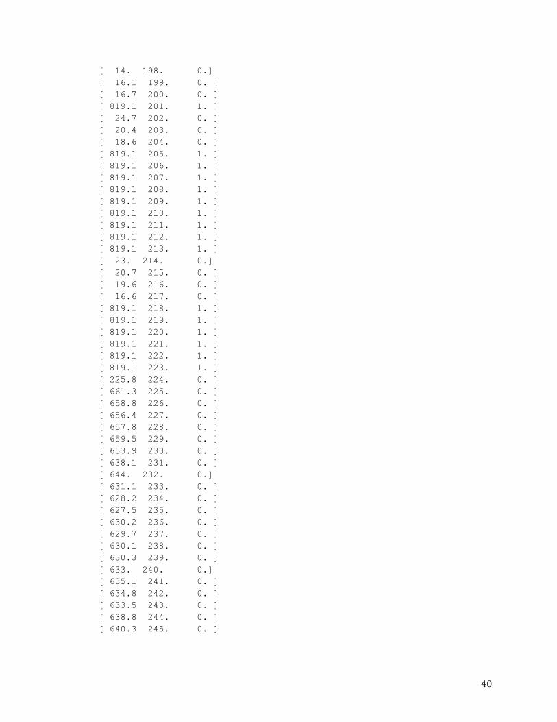
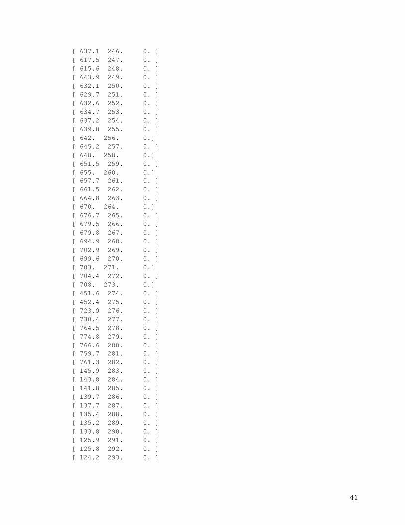
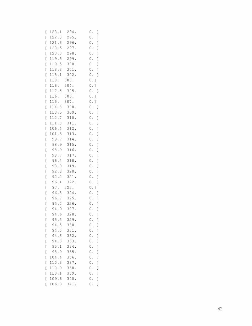
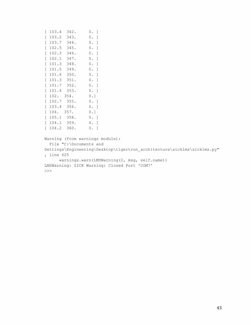
Appendix F: Test run output of LMS Sensor Interface Code
This is the output taken from the Python Shell after performing a test run of the
code for the Sensor Interface for the Laser Rangefinder. This output verifies the
functionality of the interface code.
>>> ================================ RESTART
================================
>>>
Probing for LMS on: [0, 1, 2, 3, 4, 5, 6, 7, 8, 9, 10, 11, 12, 13, 14,
15, 16, 17, 18, 19, 20, 21, 22, 23, 24, 25, 26, 27, 28, 29]
Warning (from warnings module):
File "C:\Documents and
Settings\Engineering\Desktop\tigertron_architecture\sicklms\sicklms.py"
, line 620
warnings.warn(LMSWarning(3, msg, self.name))
LMSWarning: SICK Error: could not open port COM1: [Error 2] The system
cannot find the file specified.
Warning (from warnings module):
File "C:\Documents and
Settings\Engineering\Desktop\tigertron_architecture\sicklms\sicklms.py"
, line 620
warnings.warn(LMSWarning(3, msg, self.name))
LMSWarning: SICK Error: could not open port COM2: [Error 2] The system
cannot find the file specified.
35
Warning (from warnings module):
File "C:\Documents and
Settings\Engineering\Desktop\tigertron_architecture\sicklms\sicklms.py"
, line 620
warnings.warn(LMSWarning(3, msg, self.name))
LMSWarning: SICK Error: could not open port COM3: [Error 2] The system
cannot find the file specified.
Warning (from warnings module):
File "C:\Documents and
Settings\Engineering\Desktop\tigertron_architecture\sicklms\sicklms.py"
, line 620
warnings.warn(LMSWarning(3, msg, self.name))
LMSWarning: SICK Error: could not open port COM4: [Error 2] The system
cannot find the file specified.
Warning (from warnings module):
File "C:\Documents and
Settings\Engineering\Desktop\tigertron_architecture\sicklms\sicklms.py"
, line 620
warnings.warn(LMSWarning(3, msg, self.name))
LMSWarning: SICK Error: could not open port COM5: [Error 2] The system
cannot find the file specified.
Warning (from warnings module):
File "C:\Documents and
Settings\Engineering\Desktop\tigertron_architecture\sicklms\sicklms.py"
, line 620
warnings.warn(LMSWarning(3, msg, self.name))
LMSWarning: SICK Error: could not open port COM6: [Error 2] The system
cannot find the file specified.
Set hardware version to S05063
Warning (from warnings module):
File "C:\Documents and
Settings\Engineering\Desktop\tigertron_architecture\sicklms\sicklms.py"
, line 630
warnings.warn(LMSWarning(1, msg, self.name))
LMSWarning: SICK Info: Found scanner 'LMS291;S05063;X01.27' on serial-
port 'COM7' at 38400 b/s
All Scan data
Number of lines: 361
[ 143.5 0. 0. ]
[ 142.9 1. 0. ]
[ 143.5 2. 0. ]
[ 143.1 3. 0. ]
[ 142.6 4. 0. ]
[ 142.8 5. 0. ]
36
[ 142.1 6. 0. ]
[ 141.4 7. 0. ]
[ 140.8 8. 0. ]
[ 140.3 9. 0. ]
[ 139.4 10. 0. ]
[ 27.2 11. 0. ]
[ 29.2 12. 0. ]
[ 819.1 13. 1. ]
[ 819.1 14. 1. ]
[ 819.1 15. 1. ]
[ 142.6 16. 0. ]
[ 141.7 17. 0. ]
[ 143.2 18. 0. ]
[ 143.5 19. 0. ]
[ 144. 20. 0.]
[ 143.5 21. 0. ]
[ 141.5 22. 0. ]
[ 141.4 23. 0. ]
[ 139.9 24. 0. ]
[ 137.3 25. 0. ]
[ 139.7 26. 0. ]
[ 141.4 27. 0. ]
[ 141.4 28. 0. ]
[ 140.5 29. 0. ]
[ 140. 30. 0.]
[ 140.6 31. 0. ]
[ 137.6 32. 0. ]
[ 67.7 33. 0. ]
[ 60.8 34. 0. ]
[ 58.9 35. 0. ]
[ 54.4 36. 0. ]
[ 54.2 37. 0. ]
[ 51.1 38. 0. ]
[ 44.3 39. 0. ]
[ 41.3 40. 0. ]
[ 39.6 41. 0. ]
[ 39.7 42. 0. ]
[ 39.9 43. 0. ]
[ 39.6 44. 0. ]
[ 39.4 45. 0. ]
[ 39.9 46. 0. ]
[ 39.5 47. 0. ]
[ 38.3 48. 0. ]
[ 38.5 49. 0. ]
[ 38.6 50. 0. ]
[ 38.6 51. 0. ]
[ 38.5 52. 0. ]
[ 38.4 53. 0. ]
37
[ 38. 54. 0.]
[ 38. 55. 0.]
[ 37.8 56. 0. ]
[ 37.1 57. 0. ]
[ 38. 58. 0.]
[ 37.2 59. 0. ]
[ 37.6 60. 0. ]
[ 37.6 61. 0. ]
[ 38.1 62. 0. ]
[ 37.5 63. 0. ]
[ 37.6 64. 0. ]
[ 36.8 65. 0. ]
[ 36.8 66. 0. ]
[ 36.4 67. 0. ]
[ 37.5 68. 0. ]
[ 37.8 69. 0. ]
[ 37.5 70. 0. ]
[ 37. 71. 0.]
[ 37.1 72. 0. ]
[ 37.2 73. 0. ]
[ 37.2 74. 0. ]
[ 36.3 75. 0. ]
[ 36.4 76. 0. ]
[ 36.4 77. 0. ]
[ 36.4 78. 0. ]
[ 36.4 79. 0. ]
[ 35.5 80. 0. ]
[ 35.7 81. 0. ]
[ 35.7 82. 0. ]
[ 35.7 83. 0. ]
[ 35.6 84. 0. ]
[ 34.9 85. 0. ]
[ 35. 86. 0.]
[ 35. 87. 0.]
[ 35. 88. 0.]
[ 34.8 89. 0. ]
[ 35.2 90. 0. ]
[ 35.3 91. 0. ]
[ 34.7 92. 0. ]
[ 33.1 93. 0. ]
[ 32.7 94. 0. ]
[ 33.6 95. 0. ]
[ 34.1 96. 0. ]
[ 34.3 97. 0. ]
[ 33.2 98. 0. ]
[ 32.7 99. 0. ]
[ 33.5 100. 0. ]
[ 33.4 101. 0. ]
38
[ 33.2 102. 0. ]
[ 32.9 103. 0. ]
[ 32.6 104. 0. ]
[ 32.4 105. 0. ]
[ 32.4 106. 0. ]
[ 33. 107. 0.]
[ 32.8 108. 0. ]
[ 32.8 109. 0. ]
[ 32.7 110. 0. ]
[ 32.6 111. 0. ]
[ 32.5 112. 0. ]
[ 32.7 113. 0. ]
[ 32.8 114. 0. ]
[ 34.2 115. 0. ]
[ 34.3 116. 0. ]
[ 32.6 117. 0. ]
[ 32.6 118. 0. ]
[ 32.9 119. 0. ]
[ 32.8 120. 0. ]
[ 32.4 121. 0. ]
[ 32.9 122. 0. ]
[ 32.1 123. 0. ]
[ 32.7 124. 0. ]
[ 32.7 125. 0. ]
[ 32.7 126. 0. ]
[ 32.7 127. 0. ]
[ 32.8 128. 0. ]
[ 32.8 129. 0. ]
[ 33.9 130. 0. ]
[ 32.9 131. 0. ]
[ 32.9 132. 0. ]
[ 34. 133. 0.]
[ 33.4 134. 0. ]
[ 34. 135. 0.]
[ 34.3 136. 0. ]
[ 34.1 137. 0. ]
[ 34.1 138. 0. ]
[ 34.1 139. 0. ]
[ 34.8 140. 0. ]
[ 34.9 141. 0. ]
[ 35. 142. 0.]
[ 34.6 143. 0. ]
[ 34. 144. 0.]
[ 34.7 145. 0. ]
[ 36.7 146. 0. ]
[ 35.5 147. 0. ]
[ 35.3 148. 0. ]
[ 35.6 149. 0. ]
39
[ 36. 150. 0.]
[ 37.9 151. 0. ]
[ 37.9 152. 0. ]
[ 36.8 153. 0. ]
[ 36. 154. 0.]
[ 38.3 155. 0. ]
[ 37.5 156. 0. ]
[ 45.2 157. 0. ]
[ 56.6 158. 0. ]
[ 61.5 159. 0. ]
[ 819.1 160. 1. ]
[ 819.1 161. 1. ]
[ 75.2 162. 0. ]
[ 74.4 163. 0. ]
[ 74.9 164. 0. ]
[ 74.2 165. 0. ]
[ 447.4 166. 0. ]
[ 456.5 167. 0. ]
[ 472. 168. 0.]
[ 483.8 169. 0. ]
[ 481.8 170. 0. ]
[ 485.1 171. 0. ]
[ 819.1 172. 1. ]
[ 819.1 173. 1. ]
[ 819.1 174. 1. ]
[ 819.1 175. 1. ]
[ 819.1 176. 1. ]
[ 819.1 177. 1. ]
[ 819.1 178. 1. ]
[ 819.1 179. 1. ]
[ 819.1 180. 1. ]
[ 819.1 181. 1. ]
[ 819.1 182. 1. ]
[ 819.1 183. 1. ]
[ 819.1 184. 1. ]
[ 819.1 185. 1. ]
[ 819.1 186. 1. ]
[ 819.1 187. 1. ]
[ 819.1 188. 1. ]
[ 819.1 189. 1. ]
[ 819.1 190. 1. ]
[ 12.7 191. 0. ]
[ 11.5 192. 0. ]
[ 12.4 193. 0. ]
[ 10.4 194. 0. ]
[ 10.8 195. 0. ]
[ 12.3 196. 0. ]
[ 14.2 197. 0. ]
40
[ 14. 198. 0.]
[ 16.1 199. 0. ]
[ 16.7 200. 0. ]
[ 819.1 201. 1. ]
[ 24.7 202. 0. ]
[ 20.4 203. 0. ]
[ 18.6 204. 0. ]
[ 819.1 205. 1. ]
[ 819.1 206. 1. ]
[ 819.1 207. 1. ]
[ 819.1 208. 1. ]
[ 819.1 209. 1. ]
[ 819.1 210. 1. ]
[ 819.1 211. 1. ]
[ 819.1 212. 1. ]
[ 819.1 213. 1. ]
[ 23. 214. 0.]
[ 20.7 215. 0. ]
[ 19.6 216. 0. ]
[ 16.6 217. 0. ]
[ 819.1 218. 1. ]
[ 819.1 219. 1. ]
[ 819.1 220. 1. ]
[ 819.1 221. 1. ]
[ 819.1 222. 1. ]
[ 819.1 223. 1. ]
[ 225.8 224. 0. ]
[ 661.3 225. 0. ]
[ 658.8 226. 0. ]
[ 656.4 227. 0. ]
[ 657.8 228. 0. ]
[ 659.5 229. 0. ]
[ 653.9 230. 0. ]
[ 638.1 231. 0. ]
[ 644. 232. 0.]
[ 631.1 233. 0. ]
[ 628.2 234. 0. ]
[ 627.5 235. 0. ]
[ 630.2 236. 0. ]
[ 629.7 237. 0. ]
[ 630.1 238. 0. ]
[ 630.3 239. 0. ]
[ 633. 240. 0.]
[ 635.1 241. 0. ]
[ 634.8 242. 0. ]
[ 633.5 243. 0. ]
[ 638.8 244. 0. ]
[ 640.3 245. 0. ]
41
[ 637.1 246. 0. ]
[ 617.5 247. 0. ]
[ 615.6 248. 0. ]
[ 643.9 249. 0. ]
[ 632.1 250. 0. ]
[ 629.7 251. 0. ]
[ 632.6 252. 0. ]
[ 634.7 253. 0. ]
[ 637.2 254. 0. ]
[ 639.8 255. 0. ]
[ 642. 256. 0.]
[ 645.2 257. 0. ]
[ 648. 258. 0.]
[ 651.5 259. 0. ]
[ 655. 260. 0.]
[ 657.7 261. 0. ]
[ 661.5 262. 0. ]
[ 664.8 263. 0. ]
[ 670. 264. 0.]
[ 676.7 265. 0. ]
[ 679.5 266. 0. ]
[ 679.8 267. 0. ]
[ 694.9 268. 0. ]
[ 702.9 269. 0. ]
[ 699.6 270. 0. ]
[ 703. 271. 0.]
[ 704.4 272. 0. ]
[ 708. 273. 0.]
[ 451.6 274. 0. ]
[ 452.4 275. 0. ]
[ 723.9 276. 0. ]
[ 730.4 277. 0. ]
[ 764.5 278. 0. ]
[ 774.8 279. 0. ]
[ 766.6 280. 0. ]
[ 759.7 281. 0. ]
[ 761.3 282. 0. ]
[ 145.9 283. 0. ]
[ 143.8 284. 0. ]
[ 141.8 285. 0. ]
[ 139.7 286. 0. ]
[ 137.7 287. 0. ]
[ 135.4 288. 0. ]
[ 135.2 289. 0. ]
[ 133.8 290. 0. ]
[ 125.9 291. 0. ]
[ 125.8 292. 0. ]
[ 124.2 293. 0. ]
42
[ 123.1 294. 0. ]
[ 122.3 295. 0. ]
[ 121.6 296. 0. ]
[ 120.5 297. 0. ]
[ 120.5 298. 0. ]
[ 119.5 299. 0. ]
[ 119.5 300. 0. ]
[ 118.8 301. 0. ]
[ 118.1 302. 0. ]
[ 118. 303. 0.]
[ 118. 304. 0.]
[ 117.5 305. 0. ]
[ 116. 306. 0.]
[ 115. 307. 0.]
[ 114.3 308. 0. ]
[ 113.5 309. 0. ]
[ 112.7 310. 0. ]
[ 111.8 311. 0. ]
[ 106.4 312. 0. ]
[ 101.3 313. 0. ]
[ 99.7 314. 0. ]
[ 98.9 315. 0. ]
[ 98.9 316. 0. ]
[ 98.7 317. 0. ]
[ 96.4 318. 0. ]
[ 93.9 319. 0. ]
[ 92.3 320. 0. ]
[ 92.2 321. 0. ]
[ 96.1 322. 0. ]
[ 97. 323. 0.]
[ 96.5 324. 0. ]
[ 96.7 325. 0. ]
[ 95.7 326. 0. ]
[ 94.9 327. 0. ]
[ 94.6 328. 0. ]
[ 95.3 329. 0. ]
[ 94.5 330. 0. ]
[ 94.5 331. 0. ]
[ 94.5 332. 0. ]
[ 94.3 333. 0. ]
[ 95.1 334. 0. ]
[ 98.9 335. 0. ]
[ 104.4 336. 0. ]
[ 110.3 337. 0. ]
[ 110.9 338. 0. ]
[ 110.1 339. 0. ]
[ 109.6 340. 0. ]
[ 106.9 341. 0. ]
43
[ 103.4 342. 0. ]
[ 103.2 343. 0. ]
[ 103.7 344. 0. ]
[ 102.5 345. 0. ]
[ 102.3 346. 0. ]
[ 102.1 347. 0. ]
[ 101.3 348. 0. ]
[ 101.5 349. 0. ]
[ 101.4 350. 0. ]
[ 101.3 351. 0. ]
[ 101.7 352. 0. ]
[ 101.4 353. 0. ]
[ 102. 354. 0.]
[ 102.7 355. 0. ]
[ 103.4 356. 0. ]
[ 104. 357. 0.]
[ 105.1 358. 0. ]
[ 104.1 359. 0. ]
[ 104.2 360. 0. ]
Warning (from warnings module):
File "C:\Documents and
Settings\Engineering\Desktop\tigertron_architecture\sicklms\sicklms.py"
, line 625
warnings.warn(LMSWarning(2, msg, self.name))
LMSWarning: SICK Warning: Closed Port 'COM7'
>>>


