On-Chip Bus Protocols
National Chiao Tung UniversityChun-Jen Tsai
05/3/2011
2/63
Popular On-Chip Bus Architecture
On-chip bus architecture is one of the crucialcomponents for platform-based SoC design
Popular SoC bus architecture: AMBA –ARM’s bus architecture CoreConnect –IBM’s bus architecture (for PowerPC) Wishbone –Common architecture for open source IP design
3/63
Advanced MCU Bus Architecture
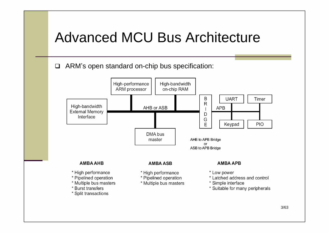
ARM’s open standard on-chip bus specification:
4/63
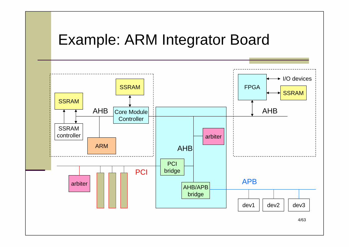
Example: ARM Integrator Board
SSRAM
SSRAMcontroller
Core ModuleController
SSRAM
ARM
arbiter
AHB
FPGAI/O devices
SSRAM
AHB
AHB/APBbridge
AHB
APB
dev1 dev2 dev3
PCIbridge
arbiter
PCI
5/63
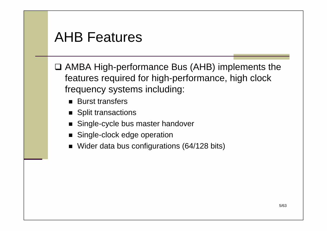
AHB Features
AMBA High-performance Bus (AHB) implements thefeatures required for high-performance, high clockfrequency systems including: Burst transfers Split transactions Single-cycle bus master handover Single-clock edge operation Wider data bus configurations (64/128 bits)
6/63
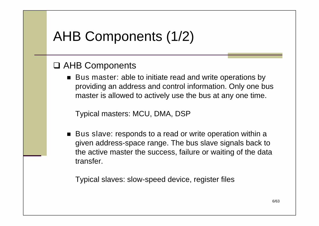
AHB Components (1/2)
AHB Components Bus master: able to initiate read and write operations by
providing an address and control information. Only one busmaster is allowed to actively use the bus at any one time.
Typical masters: MCU, DMA, DSP
Bus slave: responds to a read or write operation within agiven address-space range. The bus slave signals back tothe active master the success, failure or waiting of the datatransfer.
Typical slaves: slow-speed device, register files
7/63
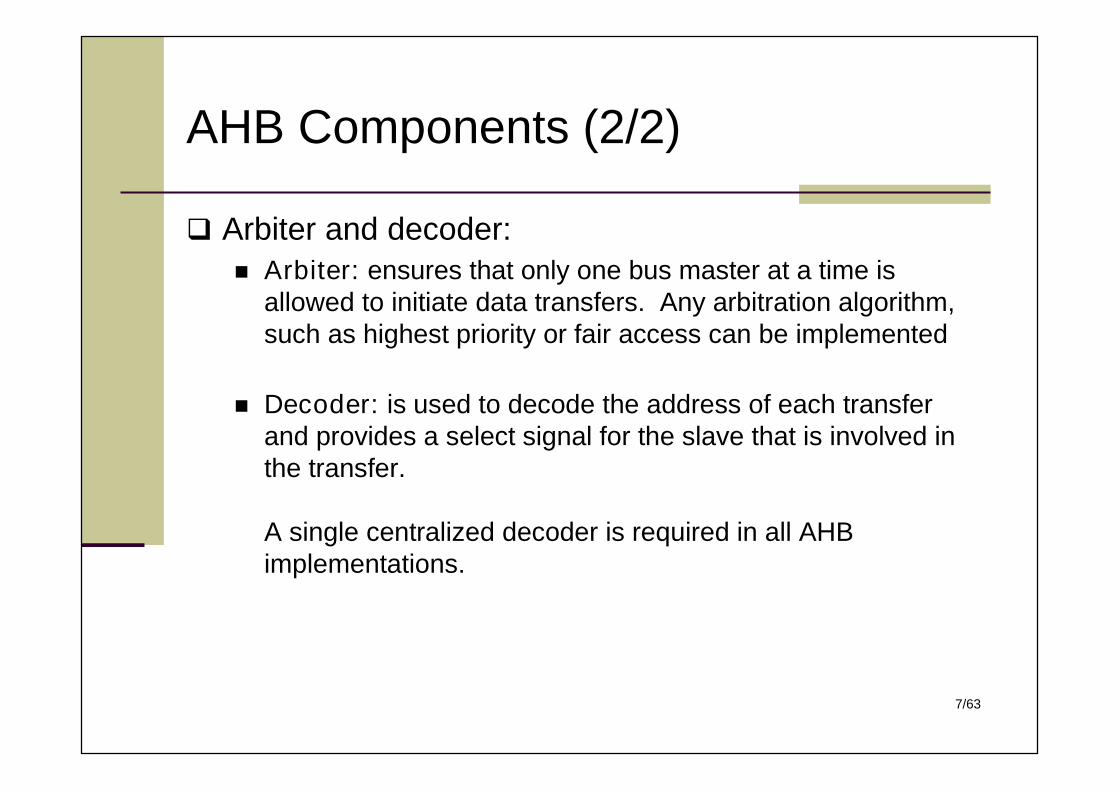
AHB Components (2/2)
Arbiter and decoder: Arbiter: ensures that only one bus master at a time is
allowed to initiate data transfers. Any arbitration algorithm,such as highest priority or fair access can be implemented
Decoder: is used to decode the address of each transferand provides a select signal for the slave that is involved inthe transfer.
A single centralized decoder is required in all AHBimplementations.
8/63
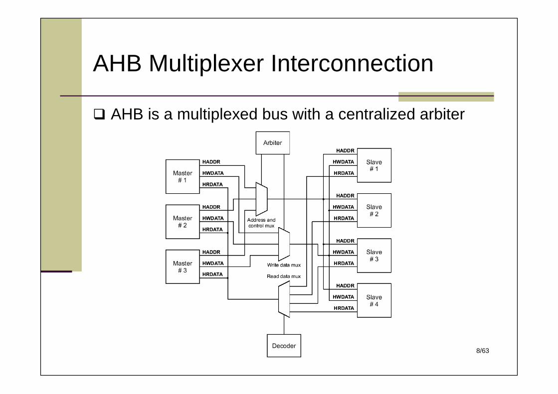
AHB is a multiplexed bus with a centralized arbiter
AHB Multiplexer Interconnection
9/63
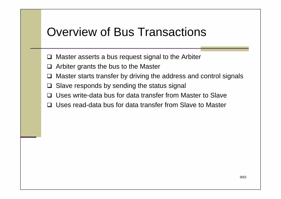
Overview of Bus Transactions
Master asserts a bus request signal to the Arbiter Arbiter grants the bus to the Master Master starts transfer by driving the address and control signals Slave responds by sending the status signal Uses write-data bus for data transfer from Master to Slave Uses read-data bus for data transfer from Slave to Master
10/63
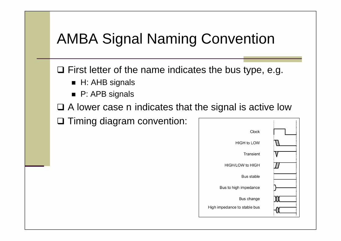
AMBA Signal Naming Convention
First letter of the name indicates the bus type, e.g. H: AHB signals P: APB signals
A lower case n indicates that the signal is active low Timing diagram convention:
11/63
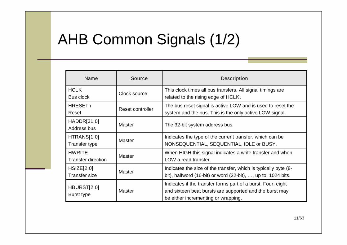
AHB Common Signals (1/2)
Indicates if the transfer forms part of a burst. Four, eightand sixteen beat bursts are supported and the burst maybe either incrementing or wrapping.
MasterHBURST[2:0]Burst type
Indicates the size of the transfer, which is typically byte (8-bit), halfword (16-bit) or word (32-bit), …, up to 1024 bits.
MasterHSIZE[2:0]Transfer size
When HIGH this signal indicates a write transfer and whenLOW a read transfer.
MasterHWRITETransfer direction
Indicates the type of the current transfer, which can beNONSEQUENTIAL, SEQUENTIAL, IDLE or BUSY.
MasterHTRANS[1:0]Transfer type
The 32-bit system address bus.MasterHADDR[31:0]Address bus
The bus reset signal is active LOW and is used to reset thesystem and the bus. This is the only active LOW signal.
Reset controllerHRESETnReset
This clock times all bus transfers. All signal timings arerelated to the rising edge of HCLK.
Clock sourceHCLKBus clock
DescriptionSourceName
12/63
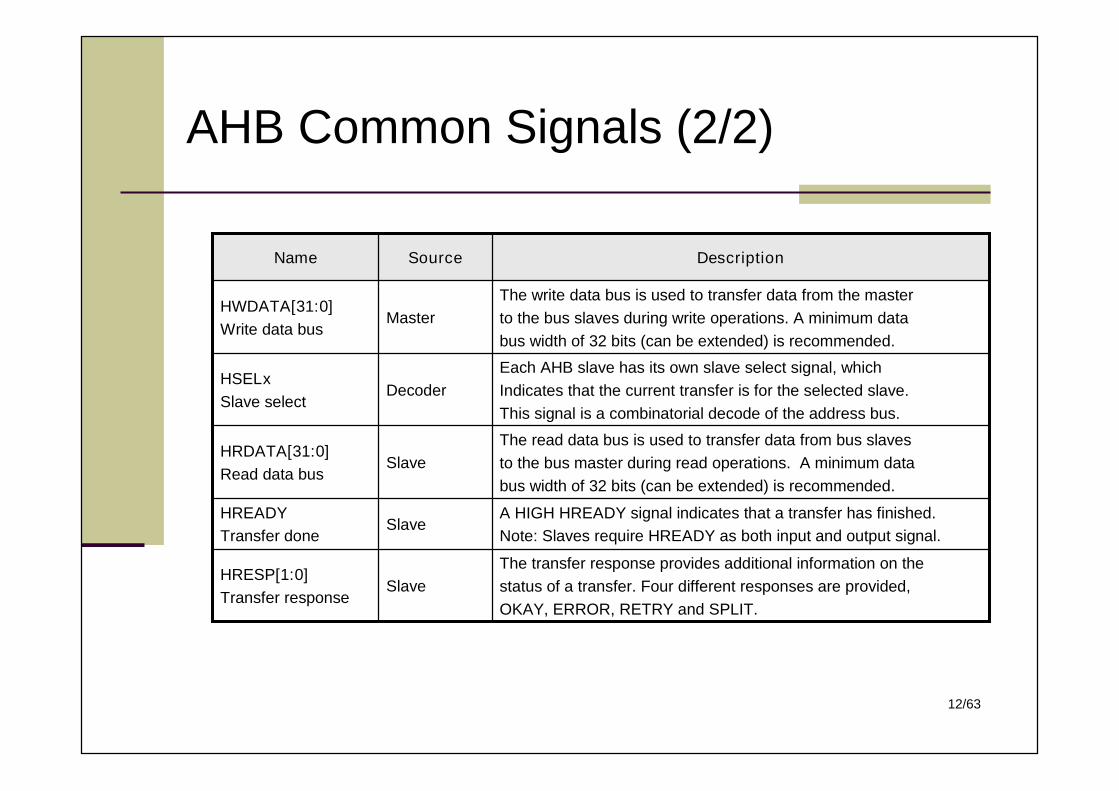
AHB Common Signals (2/2)
The transfer response provides additional information on thestatus of a transfer. Four different responses are provided,OKAY, ERROR, RETRY and SPLIT.
SlaveHRESP[1:0]Transfer response
A HIGH HREADY signal indicates that a transfer has finished.Note: Slaves require HREADY as both input and output signal.
SlaveHREADYTransfer done
The read data bus is used to transfer data from bus slavesto the bus master during read operations. A minimum databus width of 32 bits (can be extended) is recommended.
SlaveHRDATA[31:0]Read data bus
Each AHB slave has its own slave select signal, whichIndicates that the current transfer is for the selected slave.This signal is a combinatorial decode of the address bus.
DecoderHSELxSlave select
The write data bus is used to transfer data from the masterto the bus slaves during write operations. A minimum databus width of 32 bits (can be extended) is recommended.
MasterHWDATA[31:0]Write data bus
DescriptionSourceName
13/63
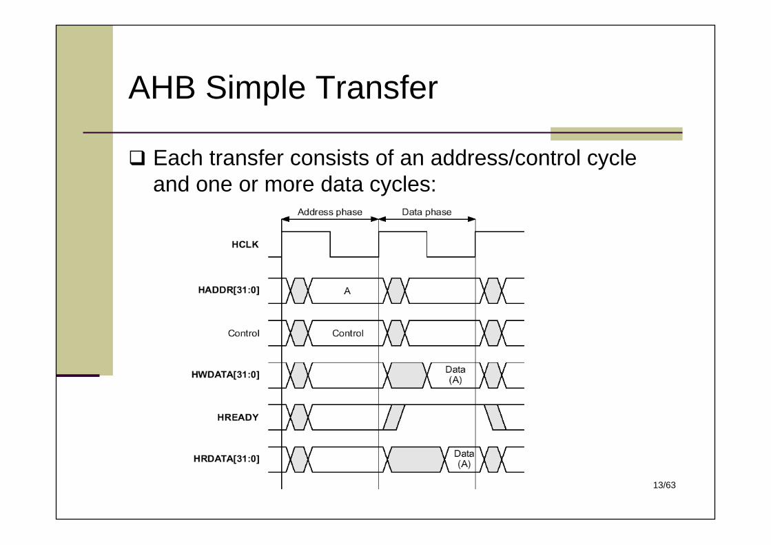
AHB Simple Transfer
Each transfer consists of an address/control cycleand one or more data cycles:
14/63
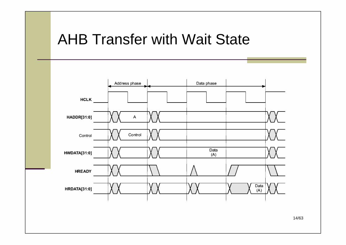
AHB Transfer with Wait State
15/63
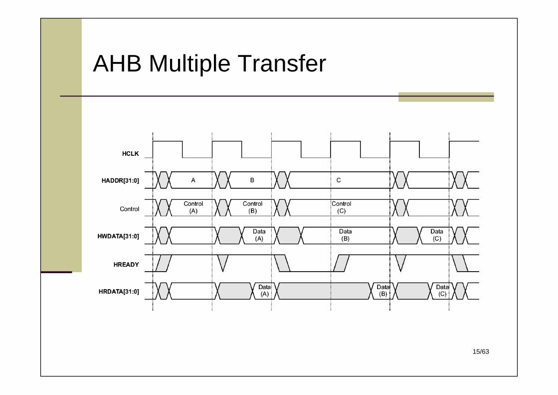
AHB Multiple Transfer
16/63
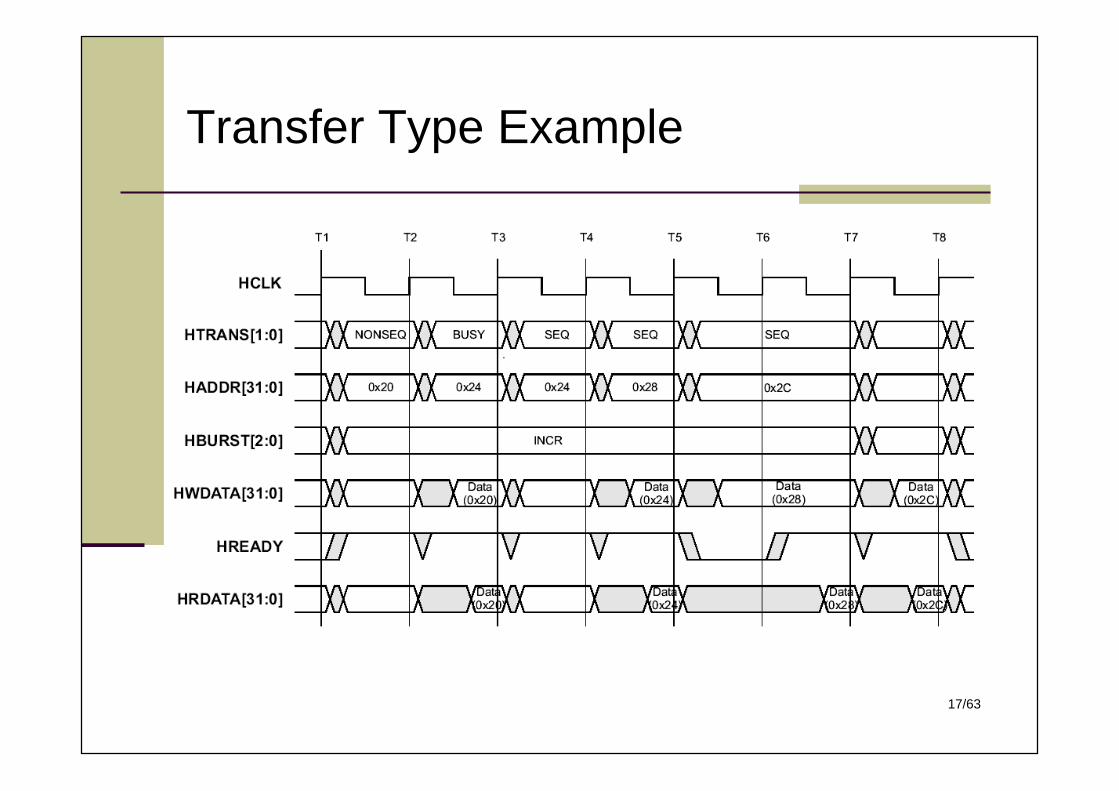
AHB Transfer Types
HTRANS[1:0] indicates the type of transfer: IDLE: masters do not need data to be transferred BUSY: allows bus masters to insert IDLE cycles in the
middle of bursts of transfers NONSEQ: The address and control signals are unrelated to
the previous transfer SEQ: the address is related to the previous transfer
17/63
Transfer Type Example
18/63
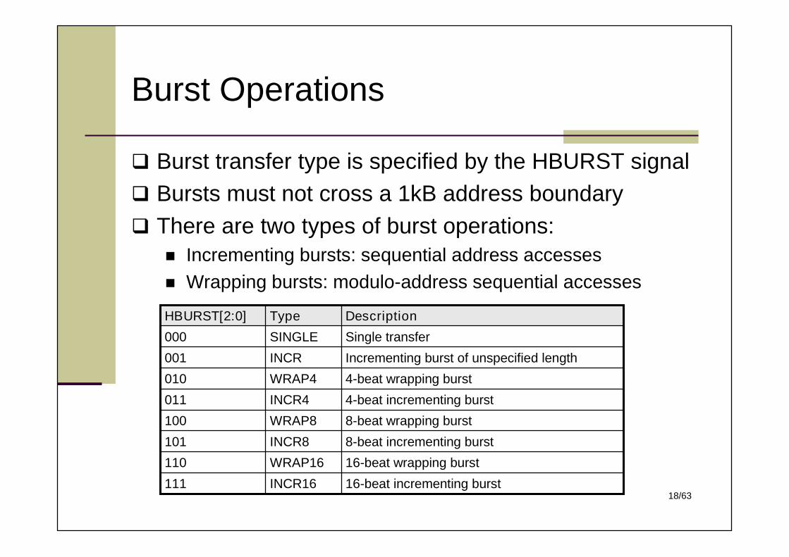
Burst Operations
Burst transfer type is specified by the HBURST signal Bursts must not cross a 1kB address boundary There are two types of burst operations:
Incrementing bursts: sequential address accesses Wrapping bursts: modulo-address sequential accesses
16-beat incrementing burstINCR16111
16-beat wrapping burstWRAP16110
8-beat incrementing burstINCR8101
8-beat wrapping burstWRAP8100
4-beat incrementing burstINCR4011
4-beat wrapping burstWRAP4010
Incrementing burst of unspecified lengthINCR001
Single transferSINGLE000
DescriptionTypeHBURST[2:0]
19/63
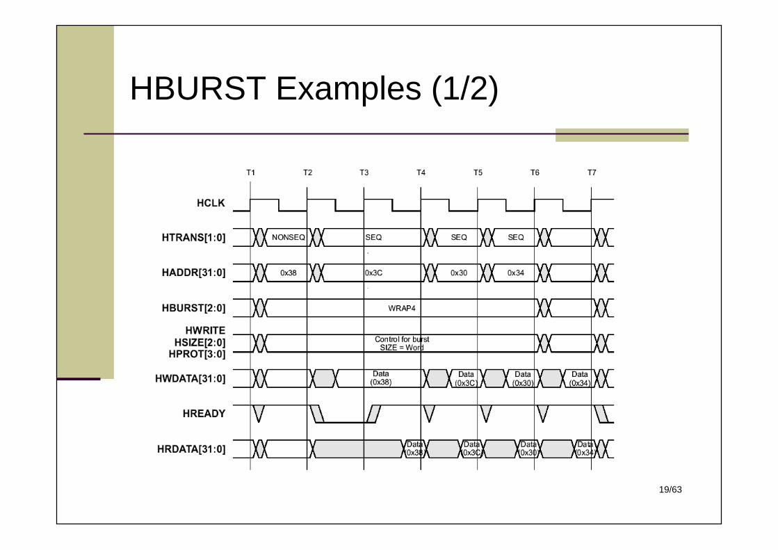
HBURST Examples (1/2)
20/63
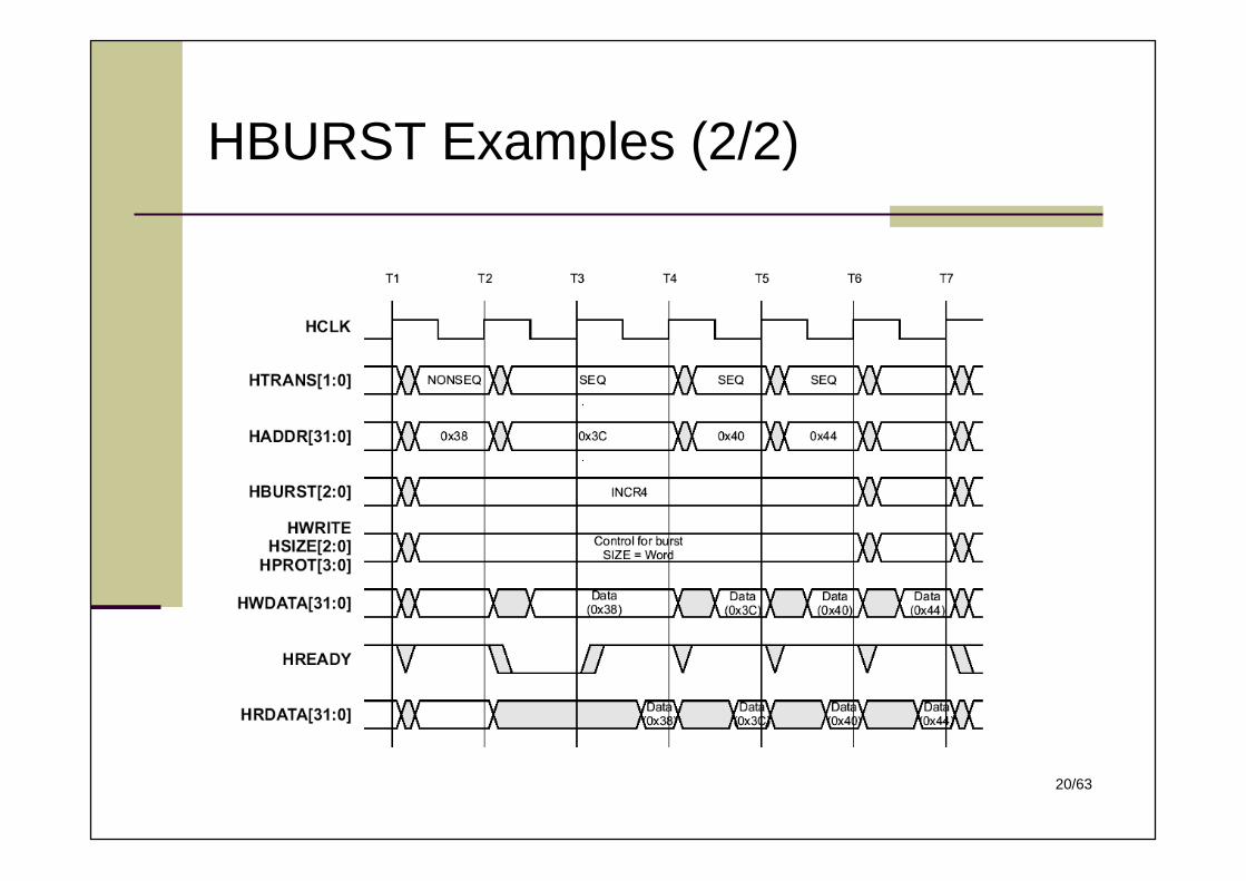
HBURST Examples (2/2)
21/63
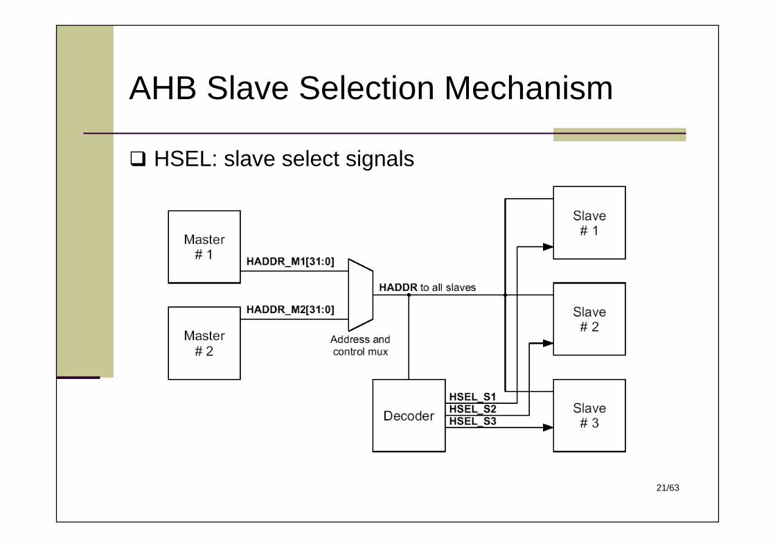
AHB Slave Selection Mechanism
HSEL: slave select signals
22/63
Slave Transfer Response
HRESP[1:0] and HREADY signals the followingconditions: OKAY: complete the transfer immediately WAIT: insert one or more wait states to allow time to
complete the transfer ERROR: signal an error to indicate that the transfer has
failed RETRY: perform the transfer again SPLIT and RETRY: delay the completion of the transfer, but
allow the master and slave to back off the bus, leaving itavailable for other transfers
23/63
AHB Arbitration (Master) Signals
HBUSREQx: (x = 0 ~ 15) Used by a bus master to request access to the bus
HLOCKx: Telling the arbiter that the master is performing a number of indivisible
transfers HGRANTx:
Generated by the arbiter; a master gains ownership of the address buswhen HGRANTx is HIGH and HREADY is HIGH at the rising edge of HCLK
HMASTER[3:0]: Indicating which master is currently granted the bus using the
HMASTER[3:0] signals HMASTLOCK:
Indicating that the current transfer is part of a locked sequence HSPLIT[15:0]
The 16-bit Split Complete bus is used by a SPLIT-capable slave to indicatewhich bus master can complete a SPLIT transaction. This information isneeded by the arbiter so that it can grant the master access to the bus tocomplete the transfer.
24/63
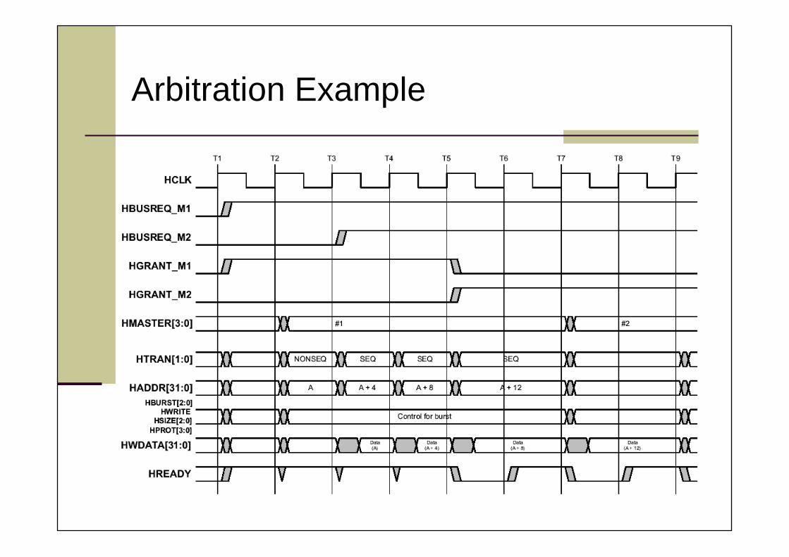
Arbitration Example
25/63
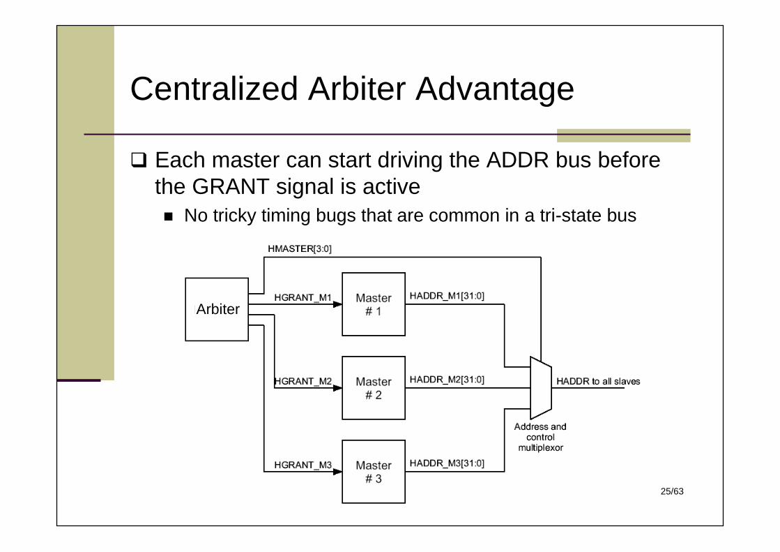
Centralized Arbiter Advantage
Each master can start driving the ADDR bus beforethe GRANT signal is active No tricky timing bugs that are common in a tri-state bus
Arbiter
26/63
Split Transactions
In AHB: Arbiter masks the request from the requesting master until
the slave is ready and then sends a grant signal to themaster
Each master can have a single outstanding split transaction A slave can have multiple outstanding split transactions no need to record address and control signals
Slave’s Responsibility: Signal a “SPLIT”response to the arbiter so that the BUS can
be given to other masters Tracking outstanding requests and matching responses In-order or out-of-order completion of outstanding requests
27/63
HADDR[2]
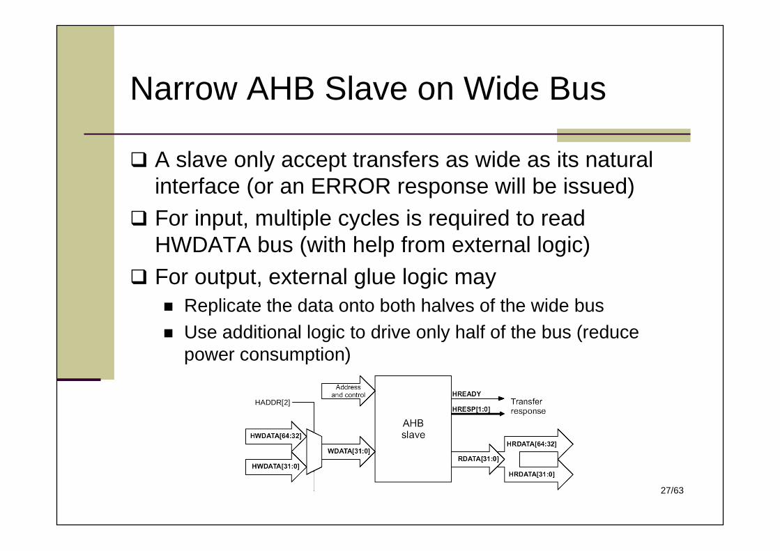
Narrow AHB Slave on Wide Bus
A slave only accept transfers as wide as its naturalinterface (or an ERROR response will be issued)
For input, multiple cycles is required to readHWDATA bus (with help from external logic)
For output, external glue logic may Replicate the data onto both halves of the wide bus Use additional logic to drive only half of the bus (reduce
power consumption)
28/63
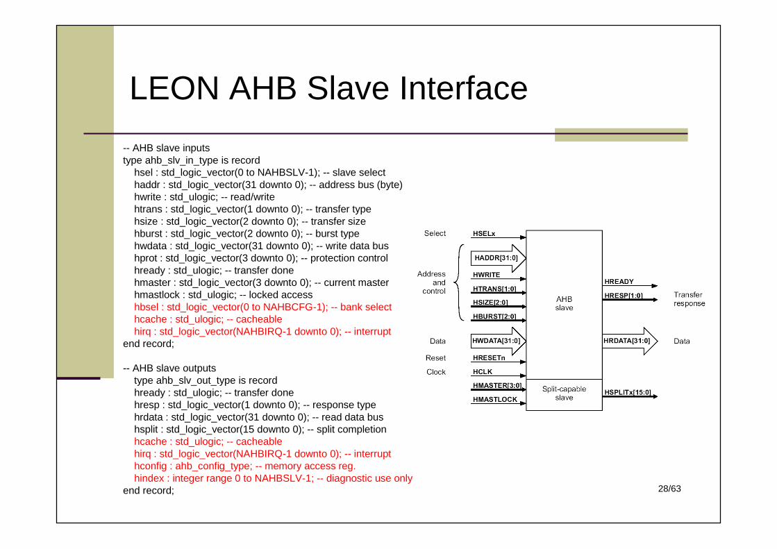
LEON AHB Slave Interface
-- AHB slave inputstype ahb_slv_in_type is record
hsel : std_logic_vector(0 to NAHBSLV-1); -- slave selecthaddr : std_logic_vector(31 downto 0); -- address bus (byte)hwrite : std_ulogic; -- read/writehtrans : std_logic_vector(1 downto 0); -- transfer typehsize : std_logic_vector(2 downto 0); -- transfer sizehburst : std_logic_vector(2 downto 0); -- burst typehwdata : std_logic_vector(31 downto 0); -- write data bushprot : std_logic_vector(3 downto 0); -- protection controlhready : std_ulogic; -- transfer donehmaster : std_logic_vector(3 downto 0); -- current masterhmastlock : std_ulogic; -- locked accesshbsel : std_logic_vector(0 to NAHBCFG-1); -- bank selecthcache : std_ulogic; -- cacheablehirq : std_logic_vector(NAHBIRQ-1 downto 0); -- interrupt
end record;
-- AHB slave outputstype ahb_slv_out_type is recordhready : std_ulogic; -- transfer donehresp : std_logic_vector(1 downto 0); -- response typehrdata : std_logic_vector(31 downto 0); -- read data bushsplit : std_logic_vector(15 downto 0); -- split completionhcache : std_ulogic; -- cacheablehirq : std_logic_vector(NAHBIRQ-1 downto 0); -- interrupthconfig : ahb_config_type; -- memory access reg.hindex : integer range 0 to NAHBSLV-1; -- diagnostic use only
end record;
29/63
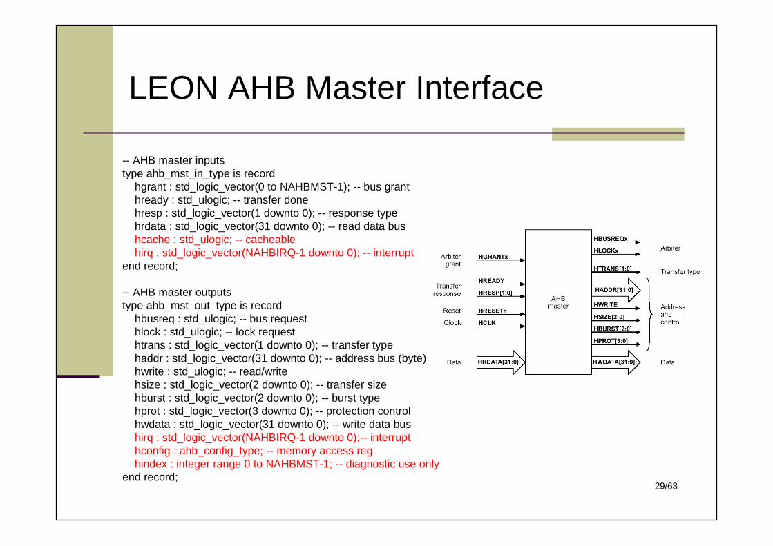
LEON AHB Master Interface
-- AHB master inputstype ahb_mst_in_type is record
hgrant : std_logic_vector(0 to NAHBMST-1); -- bus granthready : std_ulogic; -- transfer donehresp : std_logic_vector(1 downto 0); -- response typehrdata : std_logic_vector(31 downto 0); -- read data bushcache : std_ulogic; -- cacheablehirq : std_logic_vector(NAHBIRQ-1 downto 0); -- interrupt
end record;
-- AHB master outputstype ahb_mst_out_type is record
hbusreq : std_ulogic; -- bus requesthlock : std_ulogic; -- lock requesthtrans : std_logic_vector(1 downto 0); -- transfer typehaddr : std_logic_vector(31 downto 0); -- address bus (byte)hwrite : std_ulogic; -- read/writehsize : std_logic_vector(2 downto 0); -- transfer sizehburst : std_logic_vector(2 downto 0); -- burst typehprot : std_logic_vector(3 downto 0); -- protection controlhwdata : std_logic_vector(31 downto 0); -- write data bushirq : std_logic_vector(NAHBIRQ-1 downto 0);-- interrupthconfig : ahb_config_type; -- memory access reg.hindex : integer range 0 to NAHBMST-1; -- diagnostic use only
end record;
30/63
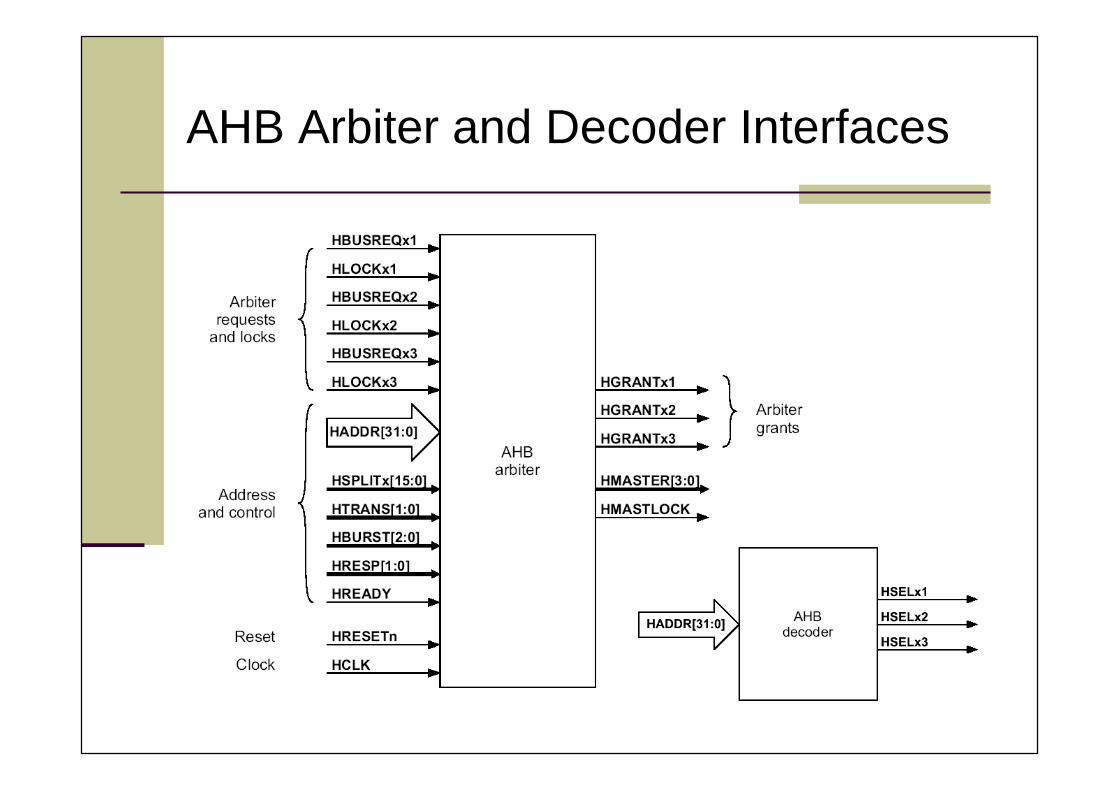
AHB Arbiter and Decoder Interfaces
31/63
APB Features
AMBA Peripheral Bus (APB) is optimized for minimalpower consumption and reduced interface complexity
All devices on APB are slaves: Unpipelined access Zero-power interface during non-peripheral bus activity Timing can be provided by decoding with strobe timing Write data valid for the whole access
32/63
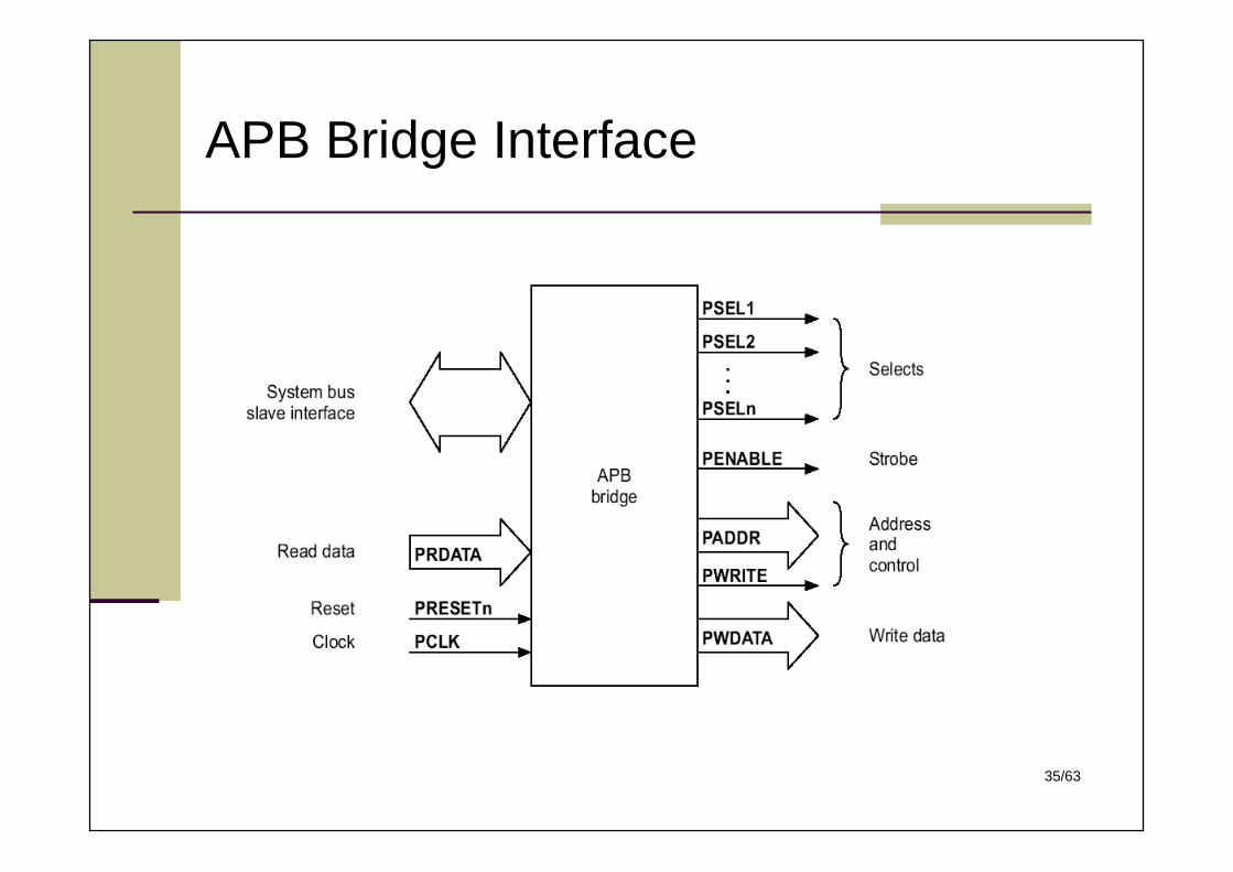
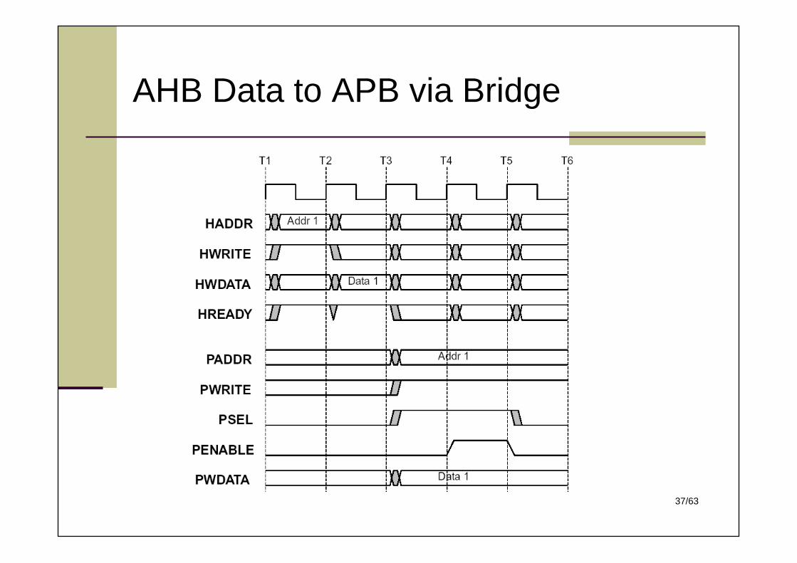
APB Bridge
The APB bridge appears as a slave module whichhandles the bus handshake and control signalretiming on behalf of the local peripheral bus
The bridge provides latching of all address, data andcontrol signals, as well as providing a second level ofdecoding to generate slave select signals for the APBperipherals
33/63
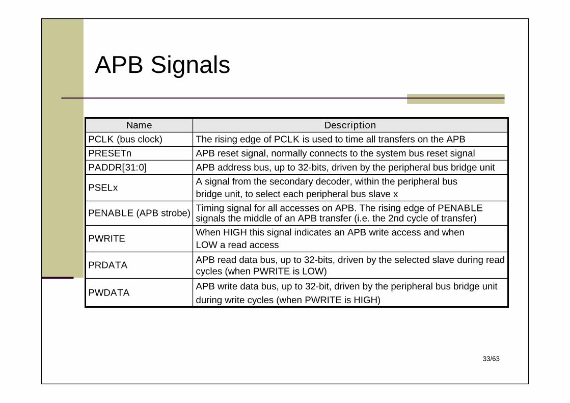
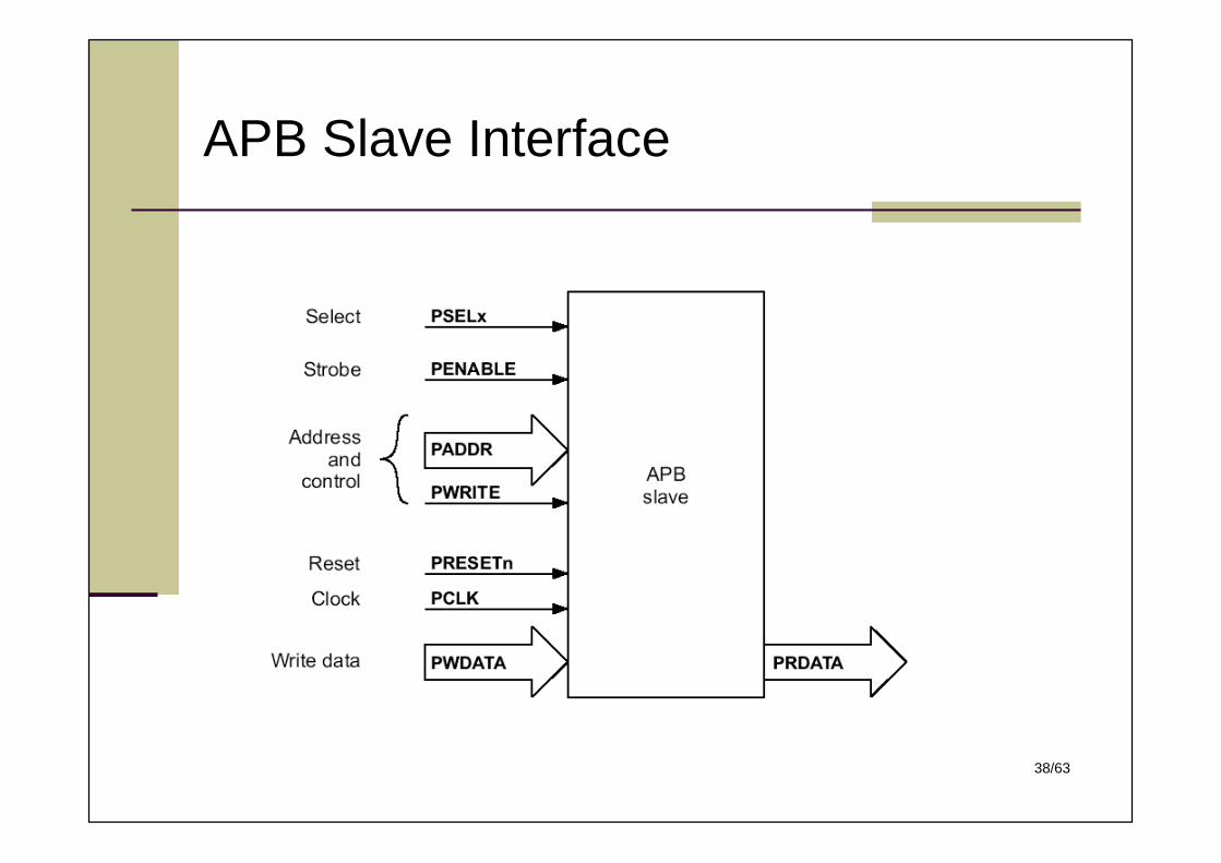
APB Signals
APB read data bus, up to 32-bits, driven by the selected slave during readcycles (when PWRITE is LOW)
PRDATA
Timing signal for all accesses on APB. The rising edge of PENABLEsignals the middle of an APB transfer (i.e. the 2nd cycle of transfer)PENABLE (APB strobe)
When HIGH this signal indicates an APB write access and whenLOW a read access
PWRITE
A signal from the secondary decoder, within the peripheral busbridge unit, to select each peripheral bus slave x
PSELx
DescriptionName
APB write data bus, up to 32-bit, driven by the peripheral bus bridge unitduring write cycles (when PWRITE is HIGH)
PWDATA
APB address bus, up to 32-bits, driven by the peripheral bus bridge unitPADDR[31:0]APB reset signal, normally connects to the system bus reset signalPRESETnThe rising edge of PCLK is used to time all transfers on the APBPCLK (bus clock)
34/63
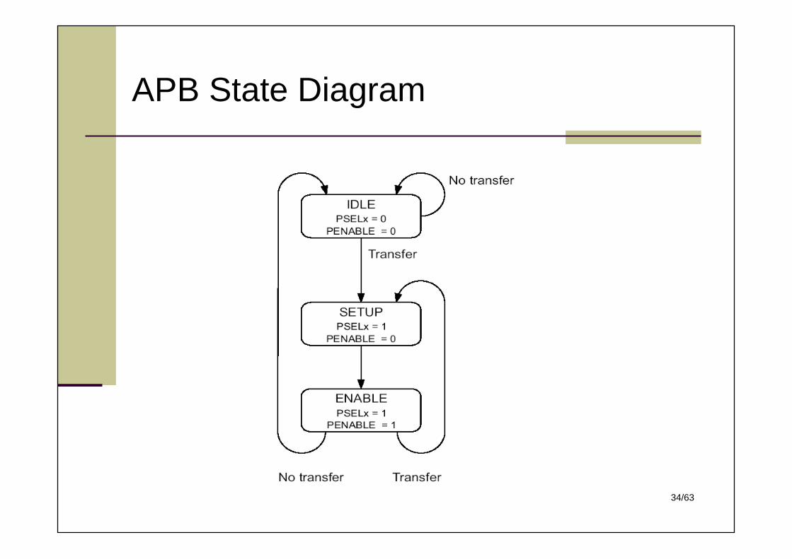
APB State Diagram
35/63
APB Bridge Interface
36/63
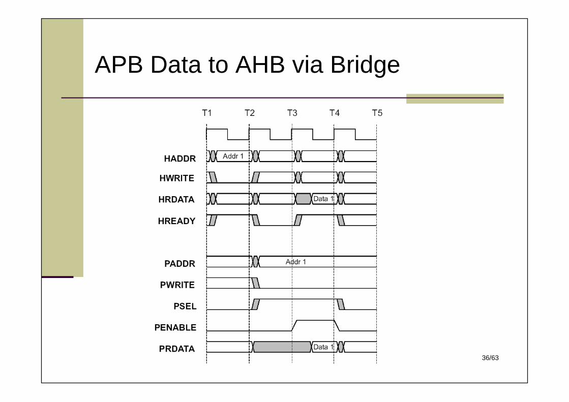
APB Data to AHB via Bridge
37/63
AHB Data to APB via Bridge
38/63
APB Slave Interface
39/63
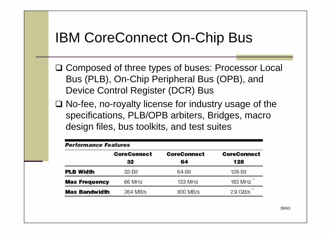
IBM CoreConnect On-Chip Bus
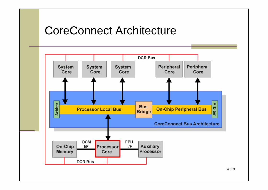
Composed of three types of buses: Processor LocalBus (PLB), On-Chip Peripheral Bus (OPB), andDevice Control Register (DCR) Bus
No-fee, no-royalty license for industry usage of thespecifications, PLB/OPB arbiters, Bridges, macrodesign files, bus toolkits, and test suites
40/63
CoreConnect Architecture
41/63
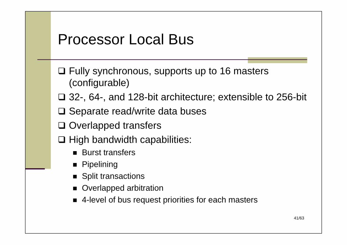
Processor Local Bus
Fully synchronous, supports up to 16 masters(configurable)
32-, 64-, and 128-bit architecture; extensible to 256-bit Separate read/write data busesOverlapped transfersHigh bandwidth capabilities:
Burst transfers Pipelining Split transactions Overlapped arbitration 4-level of bus request priorities for each masters
42/63
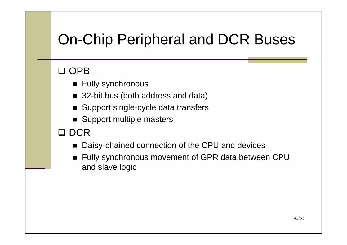
On-Chip Peripheral and DCR Buses
OPB Fully synchronous 32-bit bus (both address and data) Support single-cycle data transfers Support multiple masters
DCR Daisy-chained connection of the CPU and devices Fully synchronous movement of GPR data between CPU
and slave logic
43/63
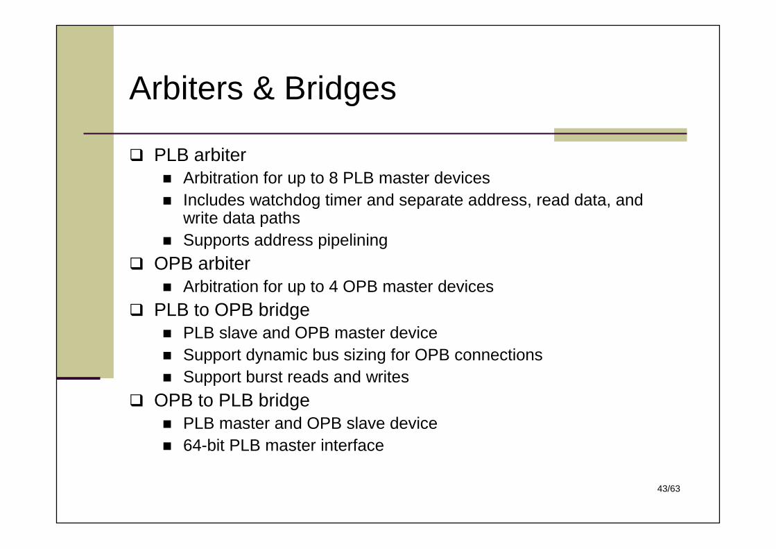
Arbiters & Bridges
PLB arbiter Arbitration for up to 8 PLB master devices Includes watchdog timer and separate address, read data, and
write data paths Supports address pipelining
OPB arbiter Arbitration for up to 4 OPB master devices
PLB to OPB bridge PLB slave and OPB master device Support dynamic bus sizing for OPB connections Support burst reads and writes
OPB to PLB bridge PLB master and OPB slave device 64-bit PLB master interface
44/63
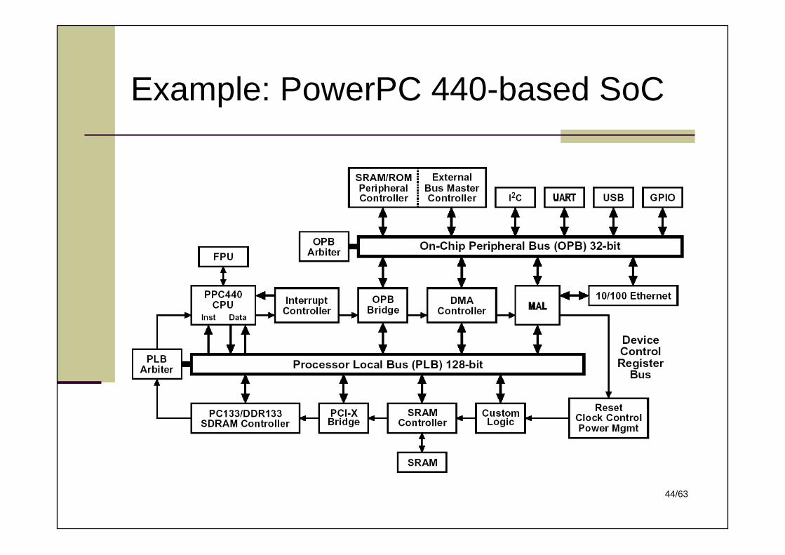
Example: PowerPC 440-based SoC
45/63
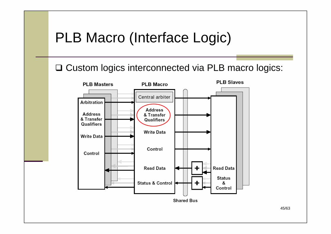
PLB Macro (Interface Logic)
Custom logics interconnected via PLB macro logics:
Central arbiter
46/63
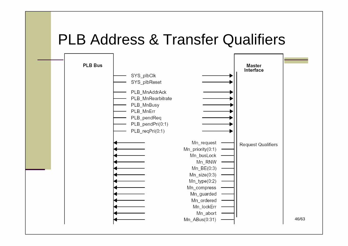
PLB Address & Transfer Qualifiers
47/63
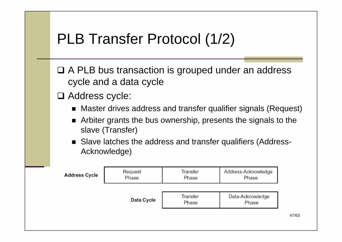
PLB Transfer Protocol (1/2)
A PLB bus transaction is grouped under an addresscycle and a data cycle
Address cycle: Master drives address and transfer qualifier signals (Request) Arbiter grants the bus ownership, presents the signals to the
slave (Transfer) Slave latches the address and transfer qualifiers (Address-
Acknowledge)
48/63
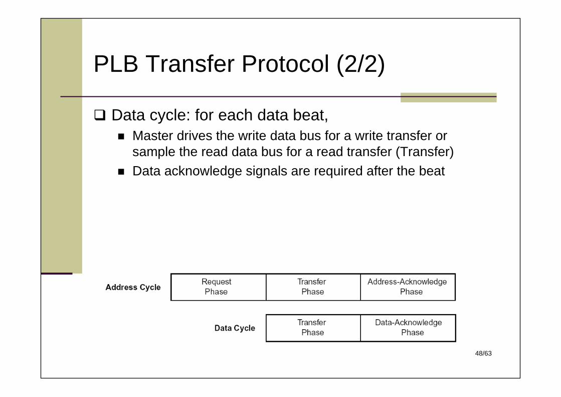
PLB Transfer Protocol (2/2)
Data cycle: for each data beat, Master drives the write data bus for a write transfer or
sample the read data bus for a read transfer (Transfer) Data acknowledge signals are required after the beat
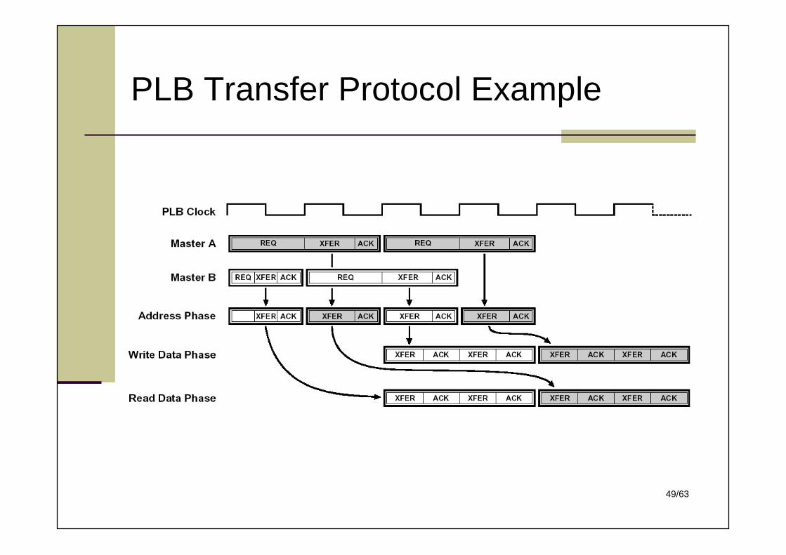
49/63
PLB Transfer Protocol Example
50/63
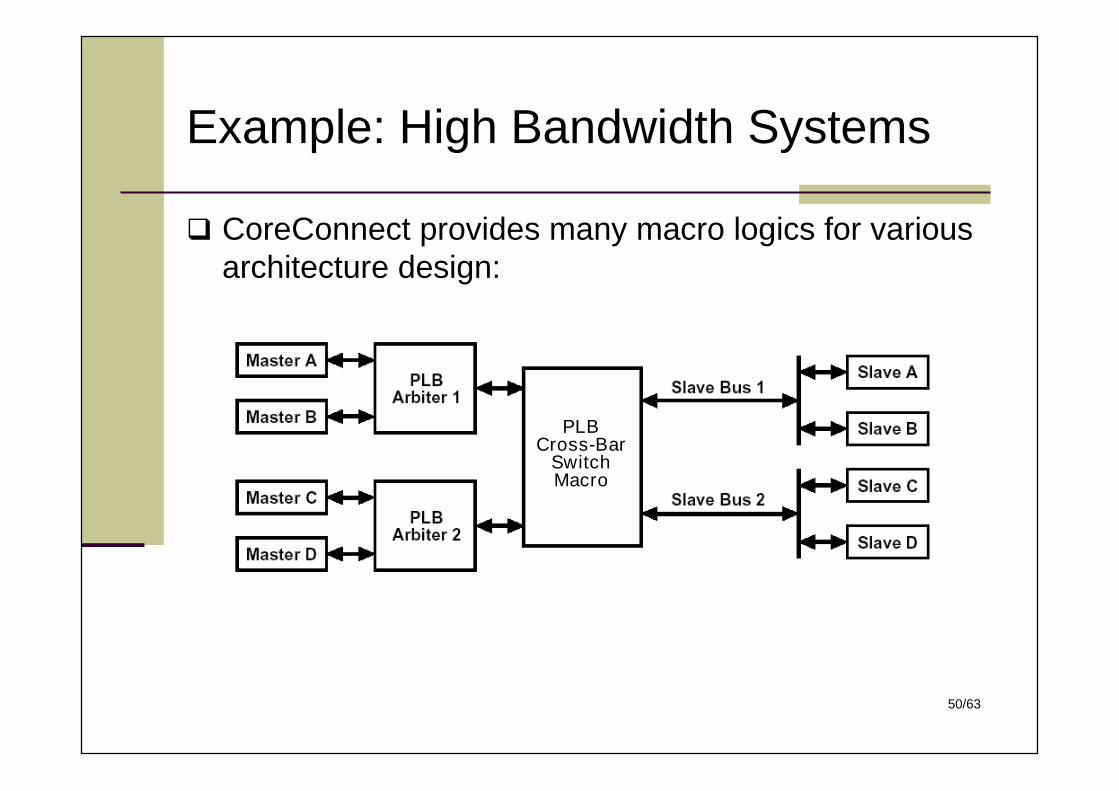
Example: High Bandwidth Systems
CoreConnect provides many macro logics for variousarchitecture design:
PLBCross-Bar
SwitchMacro
51/63
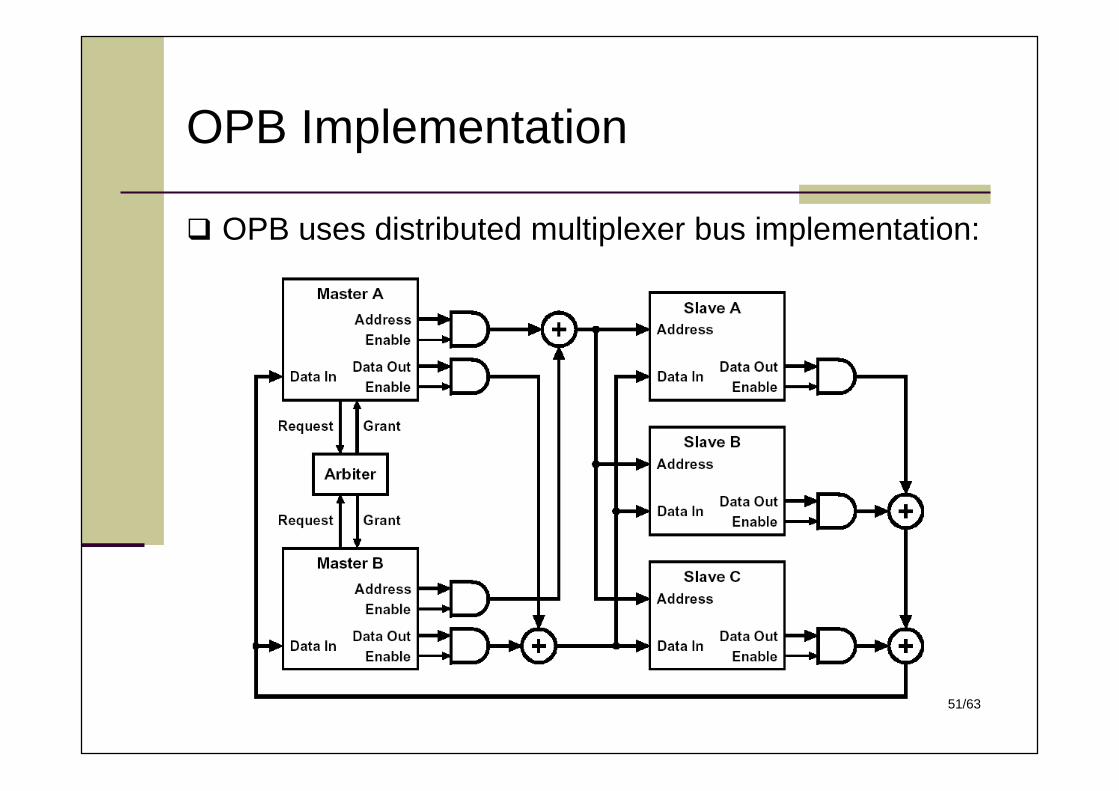
OPB Implementation
OPB uses distributed multiplexer bus implementation:
52/63
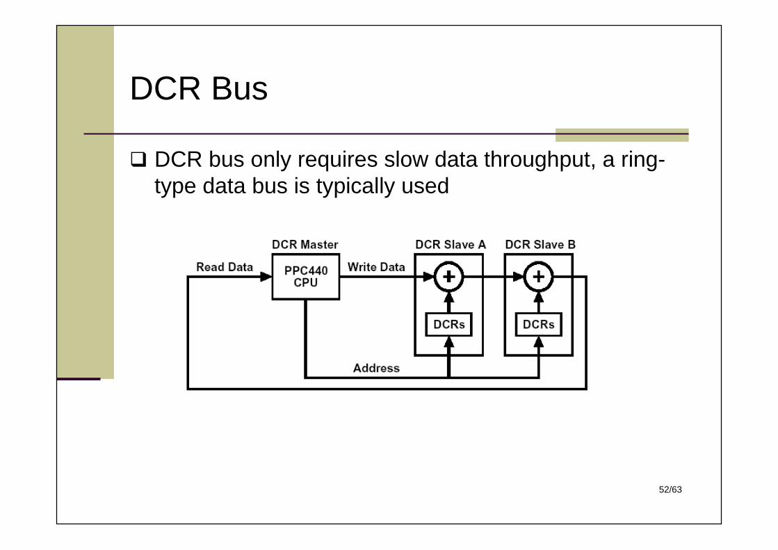
DCR Bus
DCR bus only requires slow data throughput, a ring-type data bus is typically used
53/63
Wishbone Bus
Wishbone An open bus architecture for many open-source IP projects
Features: One bus architecture for all applications (on-chip/off-chip) Supports point-to-point, shared bus, crossbar switch, and
switched fabric interconnections 64-bit address space, 8~64-bit data bus (expandable) Handshaking protocol allows each IP core to throttle its data
transfer speed Support single read and write cycles, and RMW cycles User defined TAGs for identifying data transfer types Support synchronous design for off-chip bus
54/63
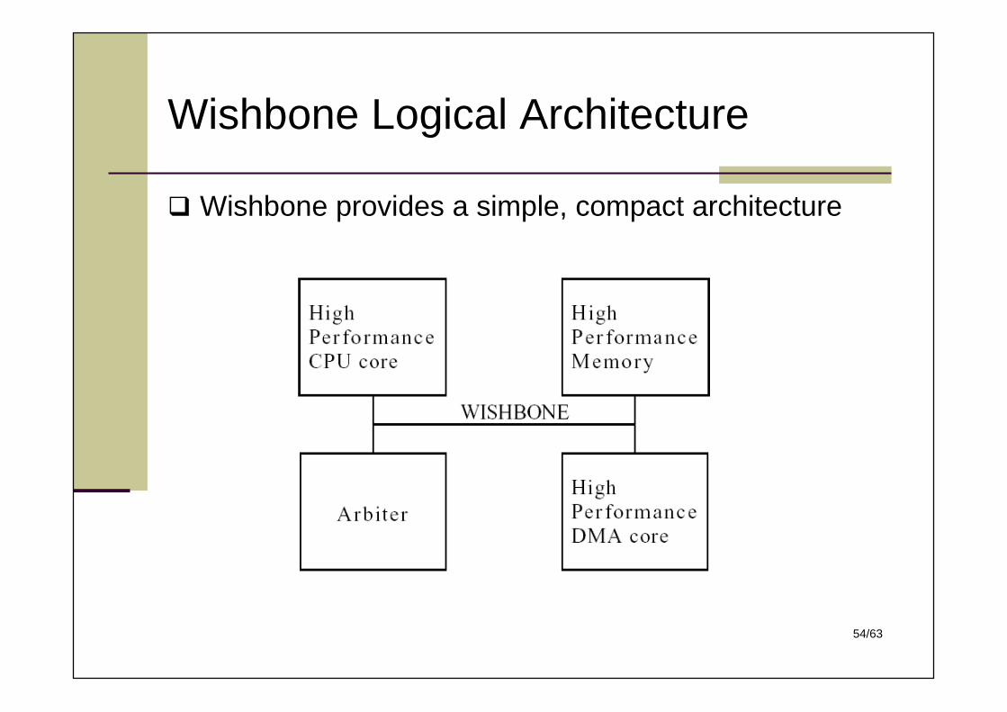
Wishbone Logical Architecture
Wishbone provides a simple, compact architecture
55/63
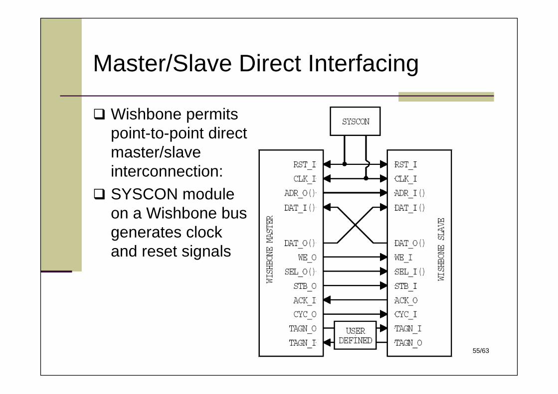
Master/Slave Direct Interfacing
Wishbone permitspoint-to-point directmaster/slaveinterconnection:
SYSCON moduleon a Wishbone busgenerates clockand reset signals
56/63
TAG Signals & Strobe Signals
There are three types of Tag signals: Data Tag,Address Tag, and Cycle Tag Timing of the tag signals are defined in the Wishbone spec.;
the semantics are defined in user IP datasheet
The strobe output [STB_O] from the master logicindicates a valid data transfer cycle; It is used toqualify various other signals on the interface such as[SEL_O()]
57/63
Example: Data Tag Signals
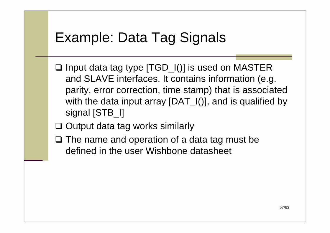
Input data tag type [TGD_I()] is used on MASTERand SLAVE interfaces. It contains information (e.g.parity, error correction, time stamp) that is associatedwith the data input array [DAT_I()], and is qualified bysignal [STB_I]
Output data tag works similarly The name and operation of a data tag must be
defined in the user Wishbone datasheet
58/63
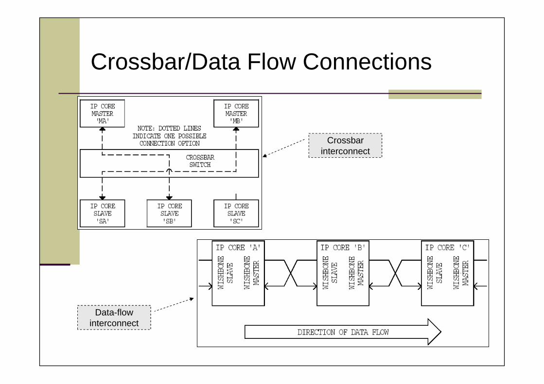
Crossbar/Data Flow Connections
Crossbarinterconnect
Data-flowinterconnect
59/63
Handshaking Protocols
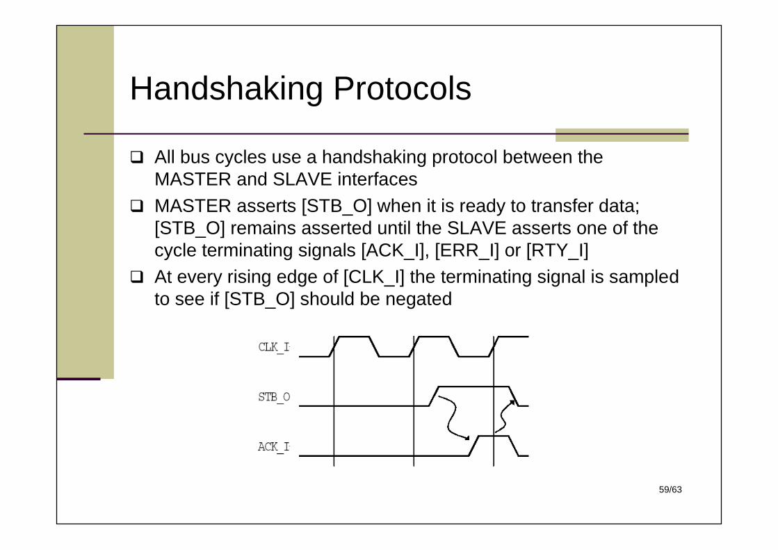
All bus cycles use a handshaking protocol between theMASTER and SLAVE interfaces
MASTER asserts [STB_O] when it is ready to transfer data;[STB_O] remains asserted until the SLAVE asserts one of thecycle terminating signals [ACK_I], [ERR_I] or [RTY_I]
At every rising edge of [CLK_I] the terminating signal is sampledto see if [STB_O] should be negated
60/63
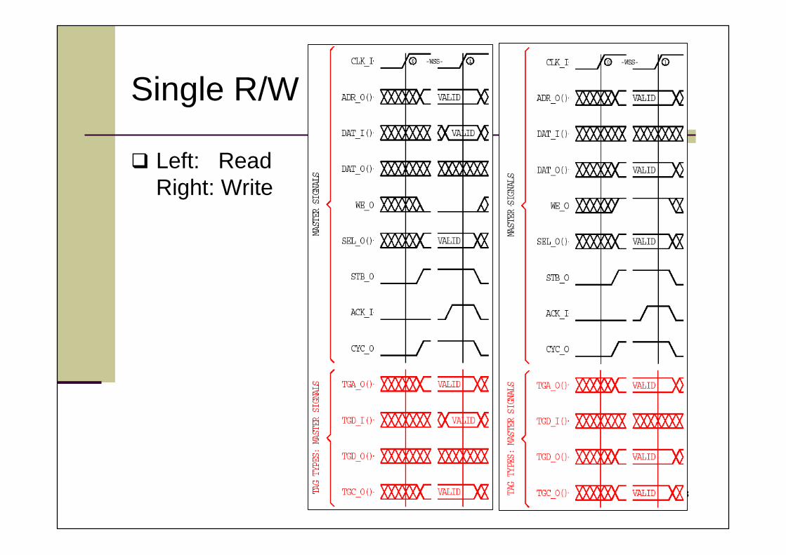
Single R/W
Left: ReadRight: Write
61/63
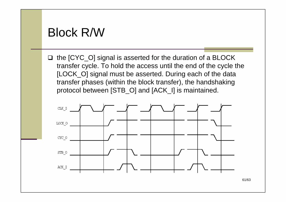
Block R/W
the [CYC_O] signal is asserted for the duration of a BLOCKtransfer cycle. To hold the access until the end of the cycle the[LOCK_O] signal must be asserted. During each of the datatransfer phases (within the block transfer), the handshakingprotocol between [STB_O] and [ACK_I] is maintained.
62/63
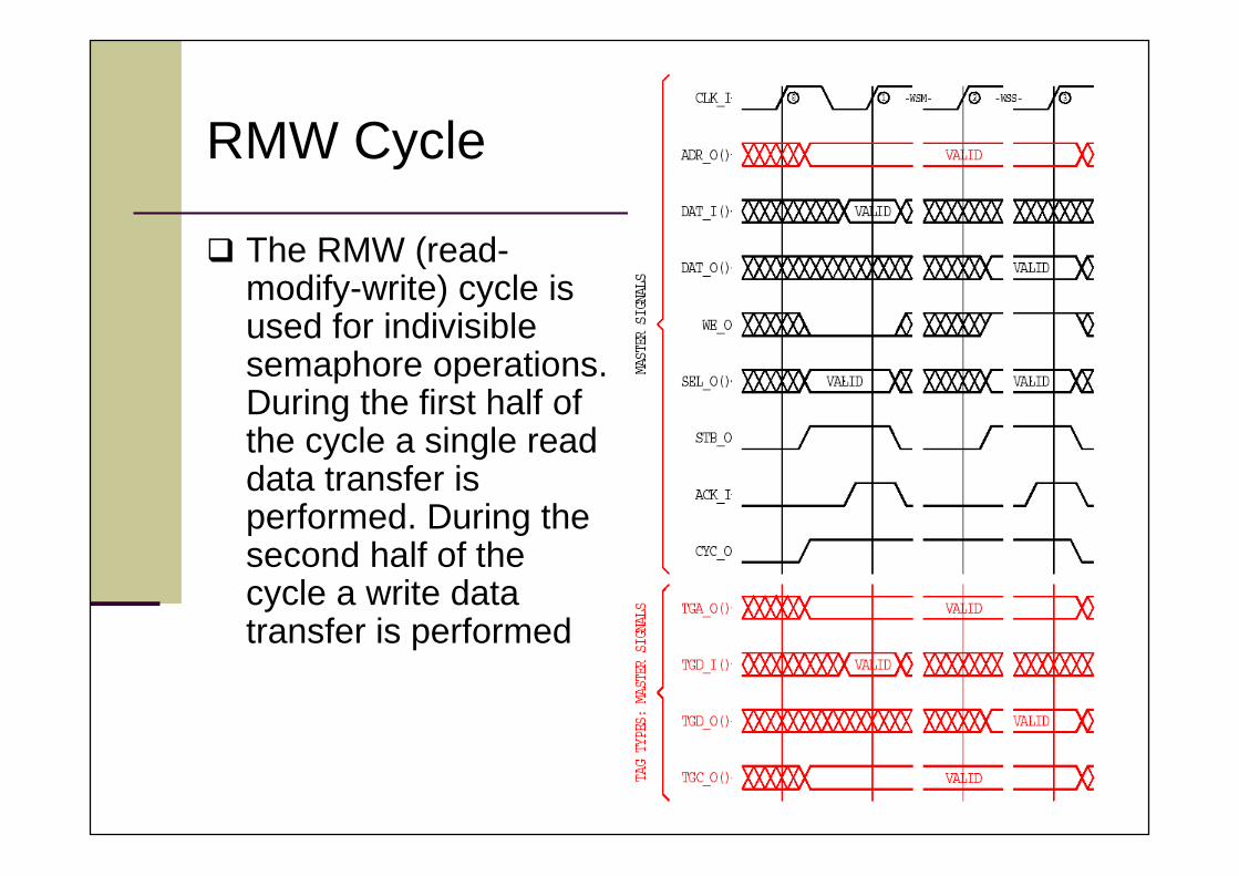
RMW Cycle
The RMW (read-modify-write) cycle isused for indivisiblesemaphore operations.During the first half ofthe cycle a single readdata transfer isperformed. During thesecond half of thecycle a write datatransfer is performed
63/63
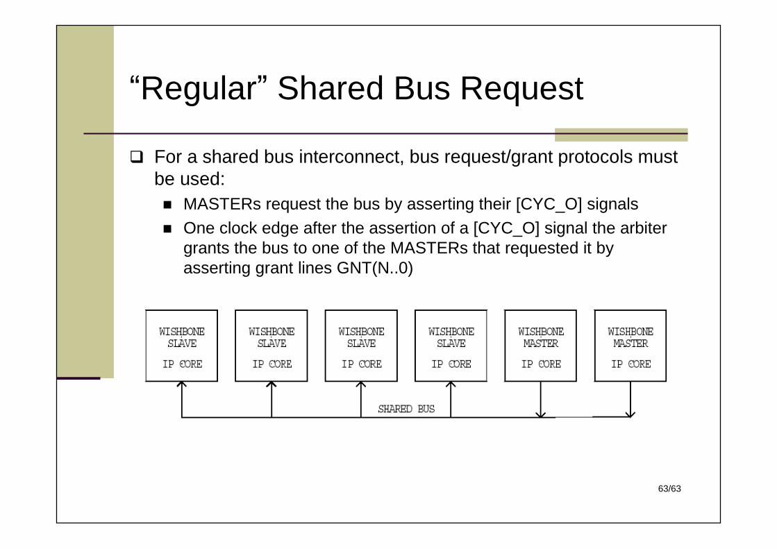
“Regular”Shared Bus Request
For a shared bus interconnect, bus request/grant protocols mustbe used: MASTERs request the bus by asserting their [CYC_O] signals One clock edge after the assertion of a [CYC_O] signal the arbiter
grants the bus to one of the MASTERs that requested it byasserting grant lines GNT(N..0)


