,
,
'" " , . \"
, ' .. ' .......... ~ ..... " ~~ ~''''} . ~.
~" "
,',
'-.. •.• ' • . -!" ....
•
"
, •• .1..
, " ,
~ ,
i . ....- ,. , .... .
•
' . " ~
"
",
... ..... ,'; . "
"
" . "
"
" ,
this Page is BIQn~: . ;
, , . ~._ ..1,'
'" ,
"
.' ,
"
,
"
-, " , :~
: of -:.,;'.: ~. ,, " .' . ", 0,
-, ~'J '-:. :-;.:: .... ~. ~ .'
, .
"
"
,
., '"
',.'
"
, ..... ' -
.~~
.. , . .I
., '
',' , "
"
" .,"
-:. ", '" ,'~
, ' . ...:;~: ~ .", '" ", <,...[ , .'
, , ,
..... , ',',
, ,:. r. ·
.. ,- . . , : .¥ ... , ... ', ,.,', . '\I,.,' ,',
• 1':.
':j; ~~ . "
. , '
" ,
,. "!"".~ , - " .. . ~ ~ .
" '
"
,
" " , • ' ,'
,."
',: ' "
"
'" ..,
.... ,
RESTRICTED
CONTENTS Page
INTRODUCTION 1
GENERAL DESCRIPTION Basic Mechanisms _________ . _ _________________ .____ 2 Types of Targets and AttacL _________ ~_____ 3 Automatic Fire Control in the Gun
Director Mk 37 System__________________ _____ 3 Tracking the Target ____ ____________________________ ~__ 3 The Rate Control Group____________________________ 3 How Rate Control Corrects Rate of
Climb, Target Speed, and Target Angle 4 Another Way to Think About Rate
Con trol _____________________________________ ~______ 5
Para llax Co rrecti on_________________________________ 5 The Star Shell ComputeL __________________________ 5 Inputs and Outputs of Computer Mk lA 5
SUMMARY OF COMPUTER MK lA D A T A ________________________________________________ ______ 6
Size - Weight - Power Supply______________ 6 Limits of Operation_________ ____ ______________________ 6 Design Features _____________ ._._._. __________________ 14
OPERATION OPERATING CONTROLS ________________________ 15 The Dials on the Front of Computer
Mk lA ________________________________ ______________________ 15
Time Motor and Power Switches ______________ 15 Initial Velocity and Dead Time __________________ 17 The Controls on the Front of Computer
Mk 1 A ________________________________________________ 17
The Controls in the Target and Ship Group ______________________________ ~ ______________________ 17
The Controls at the Range Station __ _____ ___ 17 The Controls at t he Bearing Station ____ ____ 18 The Controls at the Elevation Station ____ Ib Handcranks and Dials on the Rear Top
of the Computer ____________ ___ _________ ______________ 18 The Target Course Indicator ____________________ 19 The Star Shell Computer ________________________ __ 19
OPERATING INSTRUCTIONS ______ __ __ ____ 20 The Conditions of the Computer _____________ 20 Types of Operation __________ . _________________________ 20 Instructions for Operating Computer
Mk lA ____________ __ ________ __ ______________________________ 20
RESTRICTED
Page
Secured Condition __________________________ ______ . __ . 20 Standby Condition ____________________________________ 21 Standby for an -Air Target ____________________ ~ 21 Automatic Operation ____ . ____ . ___ .. _____ . ____ . ______ 21 Manual Operation Against an Air Target 22 Standby for a Surface Target __ ~ _______ 22 Automatic (Normal) Operation (Surface
Target ) ____________________________________________________ 22 Local Opera ti on __________ _________________________________ 22 Main Battery Operation ___ _________________________ 22 Operating Cautions ___ ._. ____ . _________________________ 22
DETAILED DESCRIPTION
Relative Motion and Integrator Groups ___ 23 Increase of Target Speed _______________________ 23 Shaft Values ______________________________________________ 23 Integra tor G roup____________________________________ ____ 23
RATE CONTROL ______ ____ _______ _____ ______________ __ 24
Handcranks and Dials Used in Rate Control ___________________________ ~~ __ 24
The Rate Control Computing Mechanism 24 The Rate Error Correction Measuring
N etwork ____________________________________ ~______ 24
Target Motion Correction Computing N etw 0 r k __________________________________________________ 25
Sensi tivi ty ControL___________________________________ 28 Sensitivity Control of Range Rate Control
N etwo r k ___________________________________________ 32
Sensitivity Control of the Elevation and Bearing Rate Control Networks _______ 32
Summary of Operation of the Elevation and Bearing Sensitivity Control N etwo r k __________ . ___________ .. ____ . _________ ______ .___ 34
Local Con tro L _____________ ________________________________ 37 Normal (Automatic) ControL _______________ 37 Automatic Tracking Controls __ .. ___ ._. _________ 37 The Control Switch ____________________ __ ~ ______ ~ 42 The Range Rate Control Switch_~ ________ 42 Time Motor Control System __________ ____________ 42 The Low E SwitclL ___________________________________ 44 The Target Course Slew System ______________ 45 Control of Range Input ______________________________ 45 Low Range Switch __________________________ ____________ 46
III

OP 10M-ADDENDUM No. I RESTRICTED
CONTENTS (Continued)
Page Page
PREDICTION SECTIOR ______________________ 46 Para llax ____ ___________ __________________ ________________ ___ 51
Computing Advance Range, R2 ______________ 47 Parallax Range ___________________________________ 51 The Elevation Prediction Network _______ 47 Computing Sight Deflection, Ds.. ____________ 48
Elevation Parallax Correction, Pe _______ 51
Computing Fuze Setting Order , F ______ 48 Ini tial V eloci ty _______ ,_________________________________ 50 MOD DIFFERENCES __________________________ 52
SPOTS ___________ ____________________ __________________________ 50
Elevation Spot for Surface Fi re _______________ 50 Gun Ord e rs _____________________________________ _____________ 50
Se ri a I N u m bers__________________________________________ 52 List of F orda lts _________________________ ________________ 52 List of Ordalts _______________________________________ _____ 53
THE SYNCHRONIZE ELEVATION Table of Modification Differences ___________ 53
GROUP ______________________________ ___________ 50
The Elevation Transmitter __________________ _ 50 COMPARATIVE INDEX ____________ __________ 57
iv RESTRICTED
RESTRICTED
Figure
1
2
3
4
5
6
7
8
9
10
11
12
13
ILLUSTRATIONS
Title Page
Computer Mk lA and Star Shell Computer Mk 1 _ _______ vi
Outline Dimensions (One Piece) _ _______ _ 7
Outline Dimensions and Weights (Two Pieces) _______ __ 7
Outline Dimensions and Weights (Four Pieces) ________________ 10
Computer Mk 1A - Operating Controls ________________ _____ __________ 14
Target and Ship Dial Group _____________________________________ 16
Target Sp~ed Dial Group ______________________________________ 16
Elevation Spot Dials _________________________________ 19
Target Motion Correction Computing Network. ____________ 26, 27
Sensi ti v i ty Control S ys tem_____ __________ _______________________________________ 28
Vector Diagrams ______ ___ __________________________________________________________ 29
Computer Time Constant Versus Range (Air Target) ____________ 30
Effect of Decreasing Upper Limit of R" _________________ 34
14 Effect of Depressing Sensitivity Push Button on Computer Time Constant_______ _ ______ 36
15 Effect of Time Constant Control Transmitter Setting on T c _______________________________________________ ___ __ _________ 36
16 Flow Schematic (Normal Control) _____________ _________________________ 38, 39
17 Automatic Operating Controls ___________________________________ AO, 41
18 Time Motor Control System _____________________________ 43
19 The dH Zeroing System _____________ 44
20 Supplemental I. V. Correction for Tf / RfL _________________ 47
21
22
23
24
RESTRICTED
Fuze Computation Network.... _______________________________________________ 49
Parallax Range N etwo r k____________________________________________________ 51
Parallax Range DiaL ________________________ ________________________ 52
Schematic Diagram, Computer Mk 1A Mod 13 _______________ __ Back
v

OP I064-ADDENDUM No. I RESTRICTED
-• -•
•
Figure' . Computer Mk JA and Star Shell Computer Mk J.
VI RESTRICTED
RESTRICTED
COMPUTER MK lA
INTRODUCTION
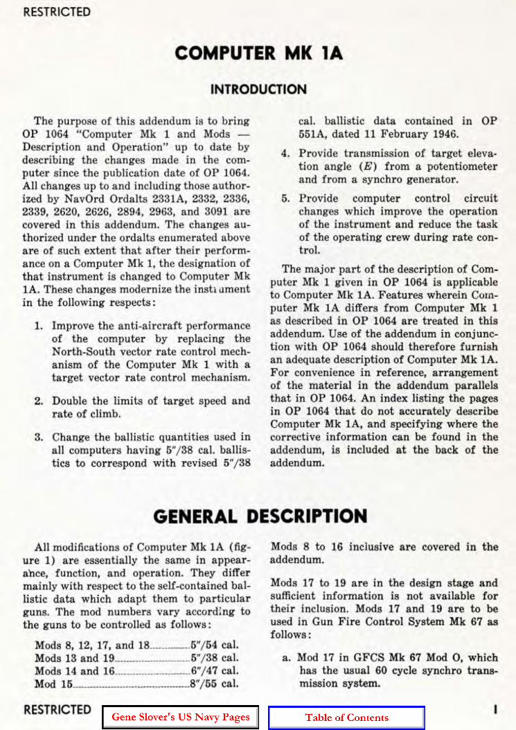
The purpose of this addendum is to bring OP 1064 "Computer Mk 1 and Mods -Description and Operation" up to date by describing the changes made in the computer since the publication date of OP 1064. All changes up to and including those authorized by NavOrd Ordalts 2331A, 2332, 2336, 2339, 2620, 2626, 2894, 2963, and 3091 are covered in this addendum. The changes authorized under the ordalts enumerated above are of such extent that after their performance on a Computer Mk I, the designation of that instrument is changed to Computer Mk IA. These changes modernize the insh llment in the following respects:
1. Improve the anti-ai rcraft performance of the computer by replacing the North-South vector rate control mechanism of the Computer Mk 1 with a target vector rate control mechanism.
2. Double the limits of target speed and rate of climb.
3. Change the ballistic quantities used in all computers having 5"/ 38 cal. ballistics to correspond with revised 5"/38
cal. ballistic data contained in OP 551A, dated 11 February 1946.
4. Provide transmission of target eleva· tion angle (E) from a potentiometer and from a synchro generator.
5. Provide computer control circuit changes which improve the operation of the instrument and reduce the task of the operating crew during rate control.
The major part of the description of Com6
puter Mk 1 given in OP 1064 is applicable to Computer Mk 1A. Features wherein Computer Mk 1A differs from Computer Mk 1 as described in OP 1064 are treated in this addendum. Use of the addendum in conjunction with OP 1064 should therefore furnish an adequate description of Computer Mk 1A. For convenience in reference. arrangement of the material in the addendum parallels that in OP 1064. An index listing the pages in OP 1064 that do not accurately describe Computer Mk 1A. and specifying where the corrective information can be found in the addendum, is included at the back of the addendum.
GENERAL DESCRIPTION All modifications of Computer Mk 1A ( fig
ure 1) are essentially the same in appearance. function. and operation. They differ mainly with respect to the self·contained ballistic data which adapt them to particular guns. The mod numbers vary accord~ng to the guns to be controlled as follows:
Mods 8, 12, 17, a nd 18._."" ..... 5"/54 cal. Mods 13 and 19 .. " .. " "" ..... "" .. ".5"/ 38 cal. Mods 14 and 16"."".".""".".".,,6"/47 cal. Mod 15 .. " .. """ .. ""." ""." ... "" ... ,,8"/55 cal.
RESTRICTED
Mods 8 to 16 inclusive are covered in the addendum.
Mods 17 to 19 are in the design stage and sufficient information is not available for their inclusion. Mods 17 and 19 are to be used in Gun Fire Control System Mk 67 as follows :
a. Mod 17 in GFCS Mk 67 Mod 0 , which has the usual 60 cycle synchro transmission system.

OP 1064 - ADDENDUM No. I
b. Mod 19 in GFCS Mk 67 Mod B, which provides for the use of 400 cycle supply in a large part of the synch ro transmission system.
Computer Mk 1A differs from Computer Mk 1 in the following general respects :
2
1. The dials and gearing have been altered to make the limits of operation of the ship speed, target speed, rate of climb, and wind speed inputs of Computer Mk lA twice the values of those in Computer Mk 1. Computer Mk lA, therefore, can be operated effectively against modern aircraft.
2. The rate control mechanism is changed. It differs f unctionally i components of target motion are taken along and at right angles to the line of sight rather than with respect to a North-South axis. One of the principal mechanical differences is the elimination of the vector solver, which was made possible by the f unctional change. Another mechanical difference is the addition of a rate of climb (dH) follow-up. The sensitivity of the mechanism has been increased, or, stated another \vay. the time constant, which is the time required to reduce an error to 37 0/0 of its ini tial value, has been decreased. Greater flexibility of operation is obtained by the addition of the means whereby the time constant can be varied at the will of the operator.
3. A number of automatic operating controls have been added, resulting in more satisfactory operation of the gun fi re control system as a whole, and in simplification of the task of the computer operating crew.
4. An additional I . V . correction is applied in the predictor section of Computer Mk 1A Mods 13, 14, 15, and 16 by means of an I . V. knob on the front of the computer.
5. Certain servo motor circuits have been modified to reduce oscillations in the
RESTRICTED
fuze (F), and gun elevation order (E'g) outputs.
6. The fuze computation network has been changed.
7. In Computer Mk 1A Mods 8 and 12, provision is made fo r obtaining superelevation for ranges beyond 20,000 yards in surface fire.
8. All mods of Computer IIIk 1A transmit target elevation (E) in two ways : by sy nchro transmission, and through the output of a potentiometer.
9. Computer Mk 1A Mod 15 computes and transmits values of parallax range instead of parallax in elevation due to a horizontal base ( Pv).
All of these features are dealt with in detail later.
The content of this addendum is divided into three maj or sections corresponding to the three major sections of OP 1064 and having the same designations, viz., General Description, Operation, and Detailed Description. The General Description given in OP 1064 is applicable to Computer Mk 1A when mod ified as indicated in the General Description section of this addendum. The headi ngs used in this section of the addendum correspond to those under which the same features are described in OP 1064, i.e., corresponding descriptions in the General Descri ption sections of OP 1064 and the addendum appear under the same headings. This is not exactly true for the Operation and Detailed Description sections; but the system has been followed as closely as poss ible. Reference to the comparative index at the back of this addendum will help in correlating the material in the addendum with that in OP 1064.
Basic Mechanisms In general, Computers Mk 1 and lA con
tain the same types of basic mechanisms, but they do not contain the same number of each type. The principal difference is the elimination of the vector solver and the addition of a time delay relay (agastat) .
RESTRICTED
RESTRICTED
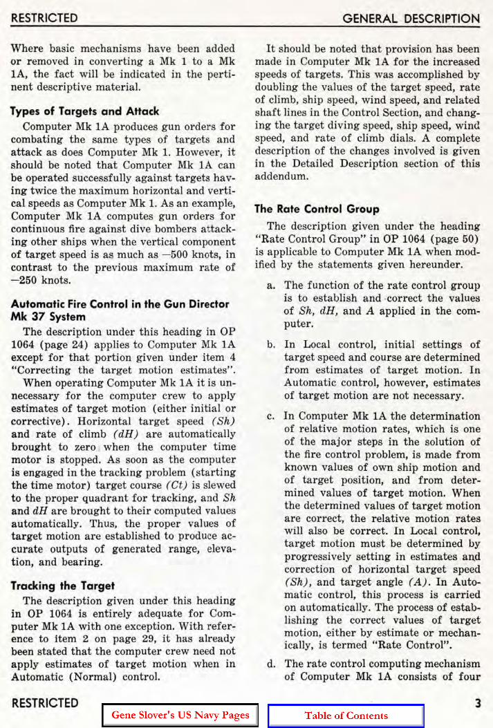
Where basic mechanisms have been added or removed in converting a Mk 1 to a Mk lA, the fact will he indicated in the pertinent descriptive material.
Types of Targets and Attack Computer Mk lA produces gun orders for
combating the same types of targets and attack as does Computer Mk 1. However, it should be noted that Computer Mk 1A can be operated successfully against targets having twice the maximum horizontal and verti cal speeds as Computer Mk 1. As an example, Computer Mk lA computes gun orders for continuous fire against dive bombers attacking other ships when the vertical component of target speed is as much as - 500 knots, in contrast to the previous maximum rate of - 250 knots.
Automatic Fire Control in the Gun Director Mk 37 System
The description under this heading in OP 1064 (page 24) applies to Computer Mk 1A except for that portion given under item 4 "Correcting the target motion estimates".
When operating Computer Mk lA it is unnecessary for the computer cr ew to apply estimates of target motion (either initial or corrective). Horizontal target speed (Sh) and rate of climb (dR) are automatically brought to zero when the computer time motor is stopped. As soon as the computer is engaged in the tracking problem (starting the time motor) target course (et) is slewed to the proper quadrant for tracking, and Sh and dH are brought to their computed values automatically. Thus, the proper values of target motion are established to produce accurate outputs of generated range, elevation, and bearing.
Tracking the Target The description given under this heading
in OP 1064 is entirely adequate for Computer Mk lA with one exception. With reference to item 2 on page 29, it has already been stated that the computer crew need not apply estimates of target motion when in Automatic (Normal) control.
RESTRICTED
GENERAL DESCRIPTION
It should be noted that provision has been made in Computer Mk 1A for the increased speeds of targets. This was accomplished by doubling the values of the target speed, rate of climb, ship speed, wind speed, and related shaft lines in the Control Section, and changing the ta rget diving speed, ship speed, wind speed, and rate of climb dials. A complete description of the changes involved is given in the Detailed Description section of this addendum.
The Rate Control Group
The description given under the heading "Rate Control Group" in OP 1064 (page 50) is applicable to Computer Mk 1A when modified by the s tatements given hereunder.
a. The function of the rate control group is to establish and -correct the values of Sh, dR , and A applied in the computer.
b. In Local control, initial settings of target speed and course are determined from estimates of target motion. In Automatic control, however, estimates of target motion are not necessary.
c. In Computer Mk lA the determination of relative motion rates, which is one of the major steps in the solution of the fi re control problem, is made from known values of own ship motion and of tar get position, and from determined values of target mot ion. When the determined values of target motion are correct, the relative motion rates will also be correct. In Local control, target motion must be determined by progressively setting in estimates and correction of horizontal target speed (Shj, and target angle (Aj. In Automatic control, this process is carried on automatically. The process of establishing the correct values of target motion. either by estimate or mechanically, is termed "Rate Control" .
d. The rate control computing mechanism of Computer Mk 1A consists of four
3

OP 10M-ADDENDUM No. I
component integrators. two disc integrators, and related gearing.
e. The rate control computing mechanism of Computer Mk lA is used only in Automatic Control. The term "Normal Control" is used to designate Automatic control in Computer Mk lA.
Automatic Rate Control. The description given on page 52 of OP 1064 for Automatic Rate Control is applicable to Computer Mk lA, but the descri ptioD on page 53 for SemiAuto is not.
Putting in range rate control corrections. The description given under this heading in OP 1064 (pages 54 and 55) is applicable to Computer Mk lA with the following exceptions.
In paragraph two of page 54 it is stated that range is received only intermittently. Computer Mk lA receives continuous inputs of range whenever the radar equipment with which the gun fire control system is equipped is utilized for ranging.
With reference to the description under the heading "In Automatic Operation" it should be noted that Computer Mk 1A operates to bring cR into synchronism with R whenever the range rate control switch is at AUTO, independently of the operation of the rangefinder's signal key. However, the input of range will not affect operation of the range rate control computing mechanism unless the key is pressed.
The description under the sub-heading "In Semi-Automatic Operation" is misleading in that it implies that the mode of operation described is appl icable only when the computer is set for Semi-Automatic control. In both Computer Mk 1 and Computer Mk 1A the mode of operation of the range rate control mechanism is controlled by one switch, the range rate control switch, while the mode of operation of the elevation and bearing rate control mechanism is controlled by another switch, designated the control switch. The computer is said to be in the type of control for which the control switch is set; but range rate control win be either automatic or manual for any type of computer
RESTRICTED
control, depending entirely on the setting of the range rate control switch. In considering operation of Computer Mk IA it should be borne in mind that there is no Semi-Automatic control, and that Automatic control is designated Normal control.
The range correction ratio changer. The description contained under the heading "The range correction integrator" in OP 1064 accurately describes this mechanism with the following exceptions. The range rate ratio knob of Computer Mk IA is graduated from 0 to 16 rather than from 1 to 5. The new figures represent range time constants in seconds (the time required to reduce the error in range to 37 70 of its initial value), rather than purely arbitrary numbered positions as formerly. Throughout the description the term "range correction integrator" should be construed as meaning "range correction ratio changer" as the name of the mechanism has been changed to lithe range correction r atio changer" in Computer Mk IA. This more accurately designates the function of the mechanism, which is to provide a means of applying a variable ratio in the iRc input line, rather than performing integrations.
How Rate Control Corrects Rate of Climb, Target Speed, and Target Angle
For illustrations pertaining to this subject reference should be made to figures 9, 10, 11, and 24 of the addendum rather than to those given on pages 56 and 57 of OP 1064. Figure 24 is a flow schematic diagram which will be found at the end of the addendum.
The description contained in OP 1064 under this heading is correct in so far as the determination of the vertical target component correction (iHe) and the horizontal component of correction (idRh) by the elevation component integrators is concerned. However, determination of the rate corrections to ta rget speed and target angle differs in Computer Mk lA from the description given in OF 1064. In this instrument, components of the horizontal rate corrections idRh and iBc are applied directly to the target vector, rather than first being resolved
RESTRICTED
RESTRICTED
into North-South and East-West components. In consequence, the cumbersome target vector solver is eliminated. In order to apply jdRh and j Bc directly to the target vector, target angle (rather than true bearing) is used to drive the vector gears of the jdRh and jBe component integrators. See figure 24.
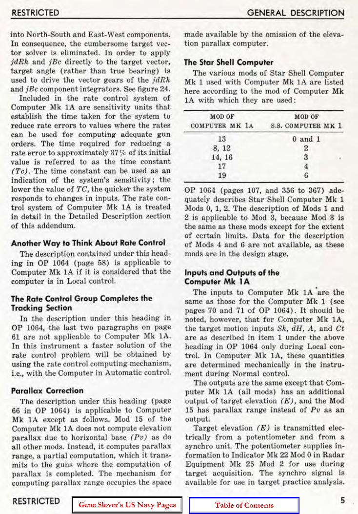
Included in the rate cont rol system of Computer Mk lA are sensitivity units that establish the t ime taken for the system to r educe rate errors to values where the rates can be used for computing adequate gun orders. The t ime required for r educing a r ate er ro r to approximately 37 9'0 of its initial value is referred to as t he time constant (Tc) . The time constant can be used as an indication of the system's sensitivity; the lower the value of TC, the quicker the system responds to changes in inputs. The rate control system of Computer Mk 1A is t reated in detail in the Detailed Description section of this addendum.
Another Way to Think About Rate Control The description contained under this head
ing in OP 1064 (page 58) is applicable to Computer Mk 1A if it is considered that the computer is in Local control.
The Rate Control Group Completes the Tracking Section
In the description under this heading in OP 1064, the last two paragraphs on page 61 are not applicable to Computer Mk 1A. In this instrument a faste r solution of the r ate control problem will be obta ined by using the rate control computing mechanism, i.e., with the Computer in Automatic control.
Parallax Correction The description under this heading (page
66 in OP 1064) is applicable to Computer Mk 1A except as follows. Mod 15 of the Computer Mk 1A does not compute elevation parallax due to horizontal base (Pv) as do all other mods. I nstead, it computes parallax range, a partial computation, which it t ransmits to the guns where the computat ion of parallax is completed. The mechanism for computing parallax r ange occupies the space
RESTRICTED
GENERAL DESCRIPTION
made available by the omission of the elevation parallax computer .
The Star Shell Computer The various mods of Star Shell Computer
Mk 1 used with Computer Mk 1A are listed here according to the mod of Computer Mk lA with which they are used:
MOD OF MOD OF
COMPUTER MK lA S.S. COMPUTER MK 1
13 8, 12 14, 16
17 19
o and 1 2 3 4 6
OP 1064 (pages 107, and 356 to 367) adequately describes Star Shell Computer Mk 1 Mods 0, 1, 2. The description of Mods 1 and 2 is applicable to Mod 3, because Mod 3 is the same as these mods except for the extent of certain limits. Data for the description of Mods 4 and 6 are not available, as these mods are in the des ign stage.
Inputs and Outputs of the Computer Mk 1 A
The inputs to Computer Mk 1A 'are the same as those for the Computer Mk 1 (see pages 70 and 71 of OP 1064) . It shOUld be noted, however, tha t for Computer Mk lA, the target motion inputs Sk, dH, A, and Ct are as described in item 1 under the above heading in OP 1064 only during Local control. In Computer Mk lA, these quantities are determined mechanically in the instrument during Normal control.
The outputs are the same except that Computer Mk 1A (all mods) has an additional output of target elevation (E), and the Mod 15 has parallax r ange instead of Pv as an output.
Target elevation ( E ) is transmitted electrically from a potentiometer and f rom a synchro unit. The potentiometer supplies information to Indicator Mk 22 Mod 0 in Radar Equipment Mk 25 Mod 2 for use during target acquisition. The synchro signal is available for use in target practice analysis.
5

OP 1064 - ADDENDUM No. I RESTRICTED <.
SUMMARY OF COMPUTER MK lA DATA
Size When shipped, the Computer Mk 1A is
stripped of protruding components, such as handcranks. switches, etc. It is shi pped in one, two, or four pieces. For use in shipping and handling, the overall dimensions of the separate pieces are given in figures 2, 3, and 4.
With Star Shell Computer Mk 1 in place, the overall height is approximately 63.4 inches. A clear height of 65 inches, measured from the base of the computer, is required for removal of the star shell computer.
Weight
The total weight of Computer Mk 1A is approximately 3150 pounds. Star Shell Computer Mk 1 weighs approximately 240 pounds. Weights of parts of Computer Mk lA, when separated as indicated in figures 3 and 4, are indicated in these figures.
Power Supply The power and synchro circuits of Com
puter Mk 1A r equire 115 volt, 60 cycle, A.C. supply. The requirements of these circuits are tabulated below. The figures given for the power circuit represent the peak requi rements for operating all servo motors of the computer. The figures given for the synchro circuit r epresent the peak requirement for excitation of the synchros in the computer only. Normal operating power for this circuit will be somewhat higher.
CIRCUITS POWER
ENERGIZED WATTS VOLTS AMPS FACTOR
Power Synchro
1060 113 496 108
Limits of Operation
9.4 42.8
1.0 .11
The limits of operation of Computer Mk lA are given in the following tables. They differ in many instances from those for Computer Mk 1.
LIMITS OF OPERATION
SYMBOL
Ds
Vs
R2
E2
cR
E
Eb + Vs
dRs
6
INTERMITTENT DRIVES
LOWER LIMIT UPPER LIMIT
320 Mils 680 Mils 390 Mi ls 590 Mils
2000' 3800' 2000' 4460'
1500 Yards 18,900 Yards
0° 90°
750 Yards 22,500 Yards
- 2° +85°
1640' 7160'
- 900 Knots + 900 Knots
Note: Only the mods listed for a particular quantity are provided with an intermittent drive for that quantity.
MOD
13 15
13 15
8,12,14,15,16
ALL
ALL
ALL
ALL
ALL
RESTRICTED

RESTRICTED
C "", ( Tr
_ t-• • < e • • • • · '~l '0 In 0 0 0 IV ~ • ~ 0 0 ~
• .. N
:--• p "
:., • ~ •
0 i:-
I 32' I Z7'- 37.6 -
6 ' . '~ 4 1. , .
MIGHT SIDE AfAR
COMPUTER frill< I"
Figure 2 . Outline Dimensions lOne PieceJ.
rrr: .; •
L9 OIIC~
0 0
n · ,~~ • •
~"., ,~ I 1-_ _ 38",=:1
00 fl • ~
:U [l
0 ~
10 •
0
C""~
-
CONTROL A ND CO MP U TER S E C T IO N S
1624 POUND S
IN DICA T OR AN D COR RE C T O R SECTI O N S
1283 POUNDS
Figure 3. Outline Di"Jension s and Weights (Two Pieces) .
RESTRICTED
I
7

OP 10M -ADDENDUM No. I RESTRICTED
LIMIT STOPS
STOP LOWER UPPER
NO. SYMBOL LIMIT LIMIT MOD
L-1 -fO o Knots 90 Knots ALL
L-2 Sh o Knots 800 Knots ALL
L-3 Sw o Knots 120 Knots ALL
L-4 dH - 500 Knots + 300 Knots ALL
L-5 dRh - 880 Knots + 880 Knots ALL
L-6 RdBs - 800 Knots + 800 Knots ALL
L-7 RdE - 800 Knots + 800 Knots ALL
L-8 dR - 900 Knots +900 Knots ALL
L-9 Ywgr - 200 Knots +200 Knots ALL . L-10 cR o Yards 35,000 Yards ALL
L-ll Eb 500' 8600' ALL
L-12 E - 25 0 +85° ALL
L-13 Range Time 1 Second (Approx.) 16 Seconds ALL
Constant
L-14 Tg +F - Tf o Seconds 50 Seconds 8, 12, 13, 14, 16 o Seconds 49 Seconds 15
L-15 IY. 2400 fs 2650 fs 8, 12 2350 fs 2600 fs 13 2250 fs 2720 fs 14, 16 2400 fs 2700 fs 15
L-16 L 480' 3520' ALL
L-17 Zd 480' 3520' ALL
L-18 jE'r 11 °40' 348°20' ALL
L-19 R2 500 Yards 18,000 Yards 13 500 Yards 20,000 Yards 8, 12, 15 500 Yards 20,200 Yards 14, 16
L-20 TfjR2 0.001184 Sec.j Y d. 0.002674 Sec.j Yd. 8, 12 0.00122 Sec./Yd. 0.00336 Sec.j Y d. 13 0.001185 Sec.j Yd. 0.002600 Sec.j Y d. 14, 16 0.001150 Sec.j Y d. 0.002300 Sec.j Yd. 15
8 RESTRICTED
RESTRICTED GENERAL DESCRIPTION
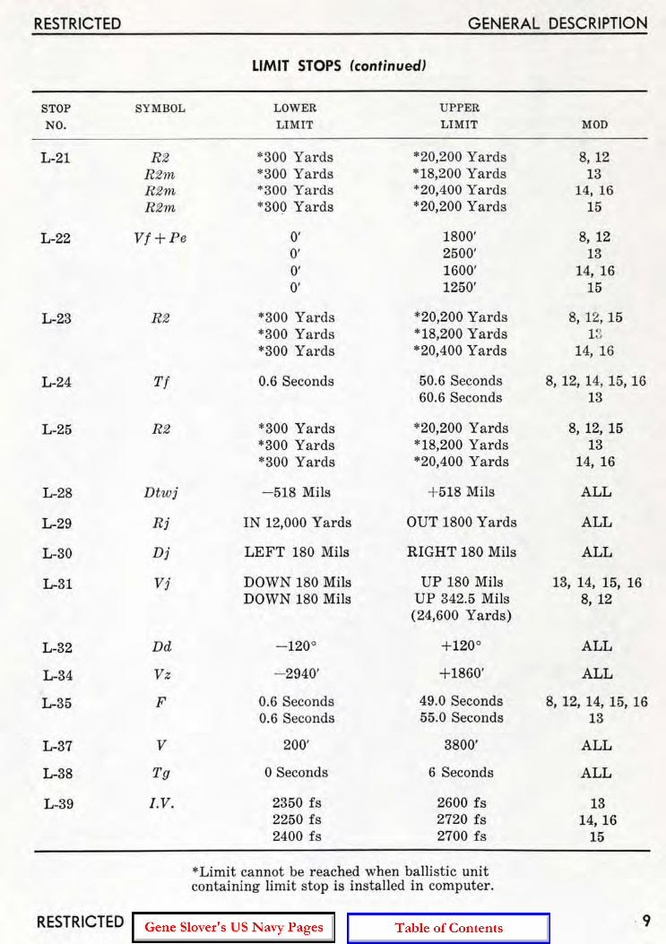
LIMIT STOPS (continued)
STOP SYMBOL LOWER UPPER
NO. LIMIT LIMIT MOD
L-21 R2 *300 Yards *20,200 Yards 8, 12 Rim, *300 Yards * 18,200 Yards 13 R2n~ ·300 Yards +20,400 Yards 14, 16 R2m '300 Yards ' 20,200 Yards 15
L-22 Vf + Pe 0' 1800' 8,12 O· 2500' 13 0' 1600' 14, 16 0' 1250' 15
L-23 R2 ' 300 Yards '20,200 Yards 8, 12, 15 '300 Yards ' 18,200 Yards 1 ~~
'300 Yards ' 20,400 Yards 14, 16
L-24 Tf 0.6 Seconds 50.6 Seconds 8, 12, 14, 15, 16 60.6 Seconds 13
L-25 R2 ' 300 Ya rds '20,200 Yards 8, 12, 15 ' 300 Yards ' 18,200 Yards 13 ' 300 Yards *20,400 Yards 14, 16
L-28 Dtwj - 518 Mils + 518 Mils ALL
L-29 Rj IN 12,000 Yards OUT 1800 Yards ALL
L-30 Dj LEFT 180 Mils RIGHT 180 Mils ALL
L-31 Vi DOWN 180 Mils UP 180 Mils 13, 14, 15, 16 DOWN 180 Mils UP 342.5 Mils 8,12
(24,600 Yards)
L-32 Dd - 1200 + 1200 ALL
L-34 Vz - 2940' +1860' ALL
L-35 F 0.6 Seconds 49.0 Seconds 8, 12, 14, 15, 16 0.6 Seconds 55.0 Seconds 13
L-37 V 200' 3800' ALL
L-38 Tg o Seconds 6 Seconds ALL
L-39 I. V . 2350 is 2600 i s 13 2250 i s 2720 i s 14, 16 2400 is 2700 is 15
- Limit cannot be reached when ballistic unit containing limit stop is installed in computer.
RESTRICTED 9

OP 10M-ADDENDUM No. I
· • ~ •
l Il
0 11 )
lr- Q
CONTROL S[C;TION
724 POUNDS
STOP
NO.
INDICATOR SECTION
299 POUNDS
COM P UTEI'! SECTION
898 POU ND S
Figure 4. Outline Dime nsions and Weights (Four Pieces'.
STAR SHELL COMPUTER MK 1
LOWER UPPER
SYMBOL L I M IT LIMIT
L-l WrD + KRdBs - 60 K nots + 60 Knots (Read as 940 Knots
on counter)
L-2 Rin IN 2857 Yards OUT 1500 Yards IN 2700 Yards OUT 1500 Yards
L·3 Fn 8.20 Seconds 41.55 Seconds 9.70 Seconds 46.70 Seconds 8.10 Seconds 46.02 Seconds
L·4 jDwn 4000 Yards 15,000 Yards 8000 Yards 19,500 Yards 7000 Yards 20,000 Yards
10
RESTRICTED
n • • "
~ll
o
CORRECTOR SECTION
98~ POUNDS
MOD
ALL
0, 1 2, 3
0, 1 2 3
0, 1 2 3
RESTRICTED
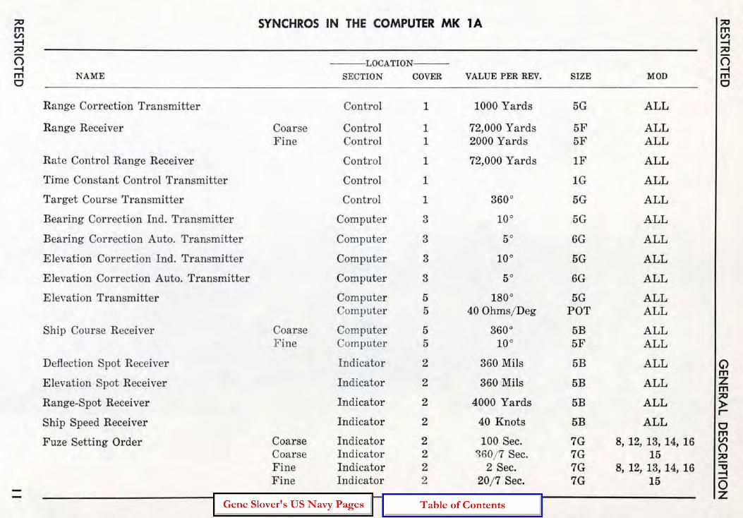
'" SYNCHROS IN THE COMPUTER MK 1 A '" m m V> V> .... .... '" '" 0 LOCATION 0 .... .... m NAME SECTION COVER VALUE PER REV. SIZE MOD m 0 0
Range Correction Transmitter Control 1 1000 Yards 5G ALL
Range Receiver Coarse Control 1 72,000 Yards 5F ALL Fine Control 1 2000 Ya rds 5F ALL
Rate Control Range Receiver Control 1 72,000 Yards IF ALL
Time Constant Control Transmitter Control 1 1G ALL
Target Course Transmitter Control 1 3600 5G ALL
Bearing Correction Ind. Transmitter Computer 3 100 5G ALL
Bearing Correction Auto. Transmitter Computer 3 50 6G ALL
Elevation Correction Ind. Transmitter Computer 3 100 5G ALL
Elevation Correction Auto. Transmitter Computer 3 50 6G ALL
Elevation Transmitter Computer 5 1800 5G ALL Computer 5 400hms/Deg POT ALL
Ship Course Receiver Coarse Computer 5 3600 5B ALL F ine Computer 5 100 5F ALL
Deflection Spot Receiver Indicator 2 360 Mils 5B ALL G'l m
Elevation Spot Receiver Indicator 2 360 Mils 5B ALL Z m
Range-Spot Receiver Indicator 2 4000 Yards 5B ALL '" » r
Ship Speed Receiver Indicator 2 40 Knots 5B ALL 0 m Fuze Setting Order Coarse Indicator 2 100 Sec. 7G 8, 12, 13, 14, 16 V>
0 Coarse Indi cator 2 %0/ 7 Sec. 7G 15 '" Fine Indicator 2 2 Sec. 7G 8, 12, 13, 14, 16 ." ::::! Fine Indicator 2 20/ 7 Sec. 7G 15 0 Z
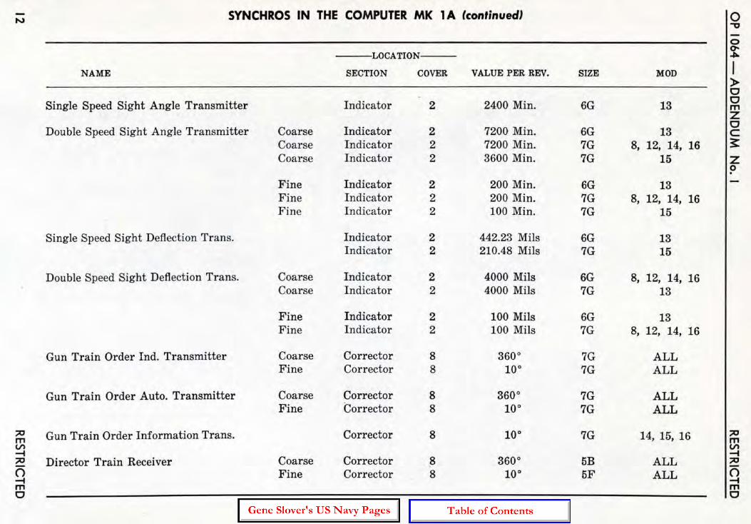
'" SYNCHROS IN THE COMPUTER MK 1 A (conlinued) 10
" 0
LOCATION If NAME SECTION COVER VALUE PER REV. SIZE MOD »-0
Single Speed Sight Angle Transmitter Indicator 2 2400 Min. 6G 13 I~ Z
Double Speed Sight Angle Transmitter Coarse Indicator 2 7200 Min. 6G 13 0 c
Coarse Indicator 2 7200 Min. 7G 8, 12, 14, 16 ;:: Coarse Indicator 2 3600 Min. 7G 15 Z
0
Fine Indicator 2 200 Min. 6G 13 Fine Indicator 2 200 Min. 7G 8, 12, 14, 16 Fine Indicator 2 100 Min. 7G 15
Single Speed Sight Deflection Trans. Indicator 2 442.23 Mils 6G 13 Indicator 2 210.48 Mils 7G 15
Double Speed Sight Deflection Trans. Coarse Indicator 2 4000 Mils 6G 8, 12, 14, 16 Coarse Indicator 2 4000 Mils 7G 13
Fine Indicator 2 100 Mils 6G 13 Fine Indicator 2 100 Mils 7G 8, 12, 14, 16
Gun Train Order Ind. Transmitter Coarse Corrector 8 3600 7G ALL Fine Corrector 8 100 7G ALL
Gun Train Order Auto. Transmitter Coarse Corrector 8 3600 7G ALL Fine Corrector 8 10 0 7G ALL
'" Gun Train Order Information Trans. Corrector 8 10 0 7G 14, 15, 16 '" m m V'> V'> .... '" Director Train Receiver Coarse Corrector
.... 8 3600 5B ALL '" 0 Fine Corrector 8 100 5F ALL 0 .... ....
m m 0 0

'" SYNCHROS IN THE COMPUTER MK 1 A (continued) '" m m V'> V'> -I -I
'" '" 0 LOCATION 0 -I -I m NAME SECTION COVER VALUE PER REV. SIZE MOD m 0 0
Gun Elevation Order Ind. Trans. Coarse Corrector 6 10,800 Min. 7G ALL Fine Corrector 6 600 Min. 7G ALL
Gun Elevation Order Auto. Trans. Coarse Corrector 6 10,800 Min. 7G ALL Fine Corrector 6 600 Min. 7G. ALL
Director Sight Elevation Coarse Corrector 6 180· 5B ALL Fine Corrector 6 10· 5F ALL
Train Parallax Transmitter Corrector 6 30· / 100 Yards 7G ALL
Elevation Parallax Transmitter Corrector 6 10·/ 100 Yards 7G 8, 12, 13, 14, 16
Parallax Range Transmitter Corrector 6 .001 Rad./y ard 7G 15
Star Shell Gun E lev. Order Trans. Coarse Star Shell 10,800 Min. 6DG 0, 1 Coarse Star Shell 10,800 Min. 6G 2 Fine Star Shell 600 Mi n. 6DG 0, 1 Fine Star Shell 600 Min. 6G 2
Star Shell Fuze Setting Order Trans. Coarse Star Shell 100 Sec. 6G 0, I, 2 Q m
Fine Star Shell 2 Sec. 6G 3 Z m
'" Star Shell Gun Train Order Trans. Coarse Star Shell 360· 6DG 0, 1 » r
Coarse Star Shell 360' 6G 2 0 Fine Star Shell 10· 6DG 0, 1 m
V'>
Fine Star S~ell 10· 6G 2 0
'" .."
Star Shell Range Spot Receiver Star Shell 4000 Yards IF 0, 1
I~ w

OP 10M-ADDENDUM No. I
Design Features
All design featu res g iven under this heading in OP 1064 are applicable to Computer Mk lA except that pertaining to initial velocity (I. V.) . The design I. V . of Computers Mk lA varies with the mod, as follows :
RESTRICTED
Mods 8, 12, 17, and 18 __ _________ _________ 2550 fs
Mod 13 ___________________________ : __________ 2500 fs
Mods 14 and 16 ____________________________ 2565 fs
Mod 15 _______________________________________ 2600 fs
Mod 19 __________________________________________ 2500 fs
STAR SHELL """. .Hoe
STA.R SHU!. RANGE KNoe Ct IUTTONS
".,MGlU.ONllE ELEVATION HANOCRANK
..... SPOT ."""""H.:,
SIGHT ANGU HAJ'OG."~"
SIGHT OEFUtT> .. ",0,,-' _ _ _, HANDCR"'"K -
SPOT
I
."ltD DIRECTION
ElEY ... :""'::==j~~~!~~~~~ SPOT I0I08 ~;;~~~~~ WINO ....... ___ -\"~ HANDeR,,"K
SHIP SPEED
TARGlT SPEED -----';---\\\ ._!-t HANOCR ..... K
RATE OF ~, •• __ ____
HANOCR .. HI(
GENERATEO ELEVATION CRANK
SENSITivity
I.Y. ""_~ _-' (HIOODf)
GENERATED aEARING CRANIC
,_ ,"III' COURSE HANDeR""K
CRANK
_ _ T;.:.ARGET ANGLE ./ HANDCfU.NK
TIME PUSHBUTTON
r ,:ON'roOt SWITCH
RANGE RATE So'!--- DIVING SPEED
HANOCRAMK
RANGE RATE f '-- CONTIltOL
MANUAL PUSHBUTTON
GENERATED RANG[ CfWoiK
RANGE ftA1£ CONTl'Ol SWITCH
'\--~~"' __ I. V. K.08
TARGET "aD SWITCH
,-~-- POWDt SWfTCH
Figure 5 . Computer Mk 'A - Ope rating Controls.
14 RESTRICTED

RESTRICTED
OPERATION
OPERATING CONTROLS
The arrangement of dials, handcranks, and switches of Computer Mk lA is t he same as that of Computer Mk 1, with the following exceptions:
1. The rate of chmb handcrank has been r elocated. The radar range receiver has been removed, and the ra te of climb hand crank is located in the cover opening previously occupied by t he r adar range receiver window.
2. The time motor switch has been removed, and a time motor push button installed adjacent to t he t a rget ~peed
dial group.
3. A sensitivity push hutton and an airsurface selector switch have been added at the elevation station.
Note: The locations of the operating controls mentioned in items 1, 2, and 3 are indicated in figure 5.
4. Three vernier dials have been added to increase the accuracy with which test problems can be set up. These a re for range (R), target angle (A), and r ate of climb (dH).
Operating dials and counters are the same as those on Computer Mk 1, except that some can indicate double their former values in order to permit tracking of targets having greater speeds.
The Dials on the Front of Computer Mk 1 A
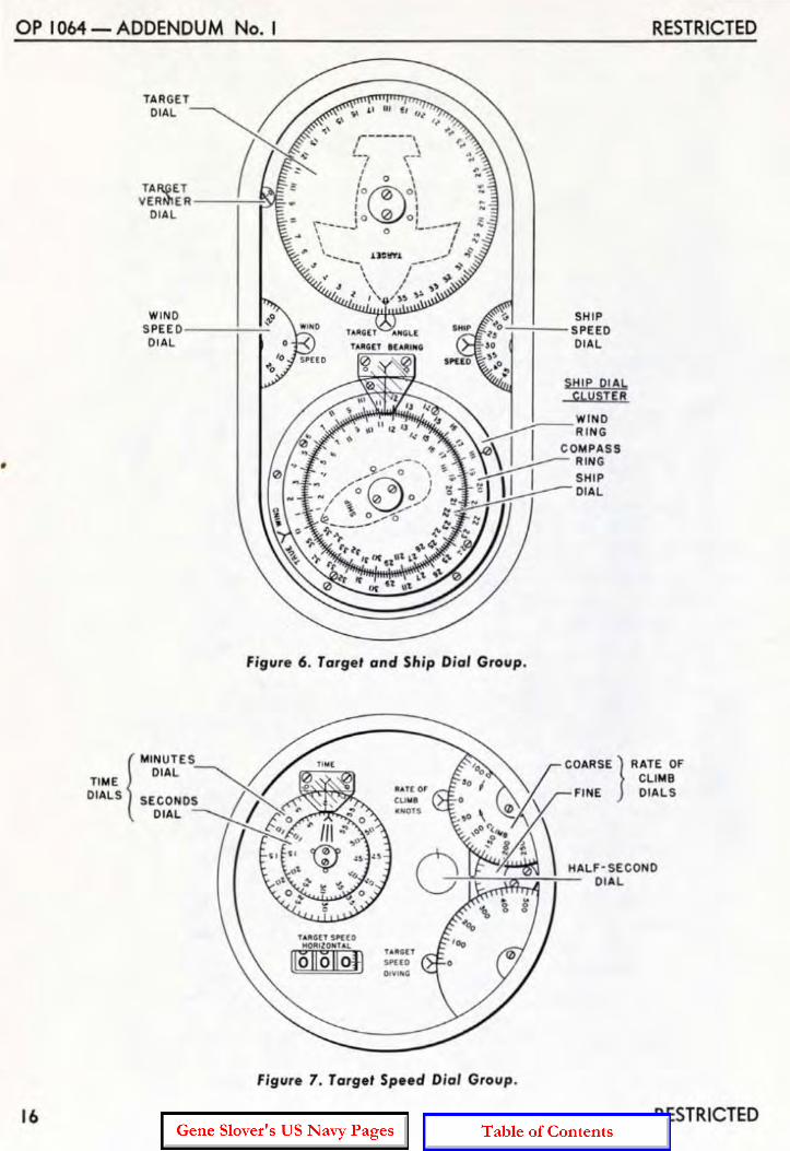
The Target and Ship Dial Group. The target and ship dial group (see figure 6) has been alte red as follows:
1. The ta rget dial gearing is equipped with a vernier dial that indicates ta rget a ngle in tenths of a degree. The vernier dial is primarily for test purposes.
RESTRICTED
2. The wind speed dial is graduated from o to 120 knots.
3. The ship speed dial is g raduated only from 0 to 50 knots, but can make a complete revolution, representing 90 knots.
The Target Speed Dial Group. This group is shown in figure 7. The target speed counter shows horizontal ground speed of the target (Sh) in knots, from 0 to 800 knots.
The rate of climb dials show rate of climb (dB) in knots. The coarse dial is graduated every ten knots from DIVE 500 knots .. through 0 to CLIMB 300 knots. A fine dial gradua ted every five knots, but unnumbered, has been added in Computer Mk 1A. When reading intermediate values on the fine dial, note should be taken of the fact that it t Urns in a direction opposite to that of the coarse dia l.
The target speed diving dial shows diving speed (S8 ). The dial is capable of rotating from 0 to ± 900 knots. However, since its primary purpose is to indicate diving speed (negative range rate), only the DIVE (minus) part is graduated and n umbered. The graduations are at 20-knot intervals.
The Range Dial Group. The r ange dial group is the same as that of Computer Mk 1 except that the radar range dial and r eceiver are not included in the Mk lAo
The range gearing of Computer lI1k 1A is equipped with a vernier r ange dial. The vernier dia l is located behind the threaded plug located in the side of the cover just below the range r eceiver dials. By means of the vernier, which has graduations at 5-yard intervals, range can be read or set to the nearest yard during test pr ocedures.
Time Motor and Power Switches
A push button, located at the range station, has been substituted fo r the time mo-
15
•
OP 10M-ADDENDUM No. I
16
TI ME
TARGET DIAL
TAR,pET ! VER~ E R --7-~'"
DIAL
WINO S PE E 0 ----7----;-:
DIAL. URfiU ~N'l[
'AliGn 1"""1111
SHIP -;--;-- SPEEO
DIAL
SHIP DIAL CbUSTER
Figure 6 . Targe, and Sh ip ~ ial Group.
{
MINUTES
DI AL 21>< DIALS SECONDS I .
DIAL / /:.,0 -<"'..,..~ .,
"'''GtT "'((0 _'ZOHUl
lioliollOJJ
figure 7. Target Speed Dial Group.
RESTRICTED
RESTRICTED

RESTRICTED
tor switch, which has been removed from the computer . Operation of the new arrangement is given under the heading, "The Controls at the Range Station",
The power switch is unchanged.
Inilial Velocity and Dead Time
Computer Mk 1A Mods 13, 14, 15, and 16 have two sets of initial velocity dia ls and knobs. One set is located on the lower left side, as in the Computer Mk 1. The other set is located on the lower front side. Both sets a re identical. These dials show the value of initial velocity (l.V.) set into the computer. They are graduated in feet per second from :
2350 fs to 2600 fs for Mod 13 2250 fs to 2720 fs for Mods 14, 16 2400 fs to 2700 fs for Mod 15
Values of initial velocity are properly set into the computer only when both dia ls read alike. A legend plate stating this is located above the front I. V. dial.
The initial velocity dia l and knob a rrangement for Computer Mk 1A Mods 8 and 12 is the same as that of Computer Mk 1. The I . V. dial of Mods 8 and 12 is graduated in feet per second f rom 2400 fs to 2650 fs .
The dead t ime dial and knob are the same as those for Computer Mk 1.
The Conlrols on Ihe Fronl of Compuler Mk 1 A
The controls on the f ront of Computer Mk 1A include the controls of the target and ship group, and those of the range station, the bearing station, and the elevation station. Differences between the cont rols a nd the description given in OP 1064 are set forth under the headings covering these separate groups below.
The Conlrols in Ihe Targel and Sh ip Group
The descript ion in OP 1064 (pages 94 and 95) adequately covers this group fo r Computer Mk 1A.
RESTRICTED
OPERATION
The Conlrols allhe Range Slation
The description given under this heading in OP 1064 (page 96) is applicable to Computer Mk 1A except as noted below.
The Control Switch. In Computer Mk lA, the three positions of the control switch are labeled NORMAL, TEST, and LOCAL in· stead of AUTO, SEMI·A UTO, and LOCAL.
With the control switch at NORMAL, bearing and elevation corrections are made automatically on signal f rom the trainer and pointer in the director.
With t he control switch at TEST, no rate corrections can be made with the generated elevation and generated bearing cranks, as formerly. These cranks, whether IN or OUT, merely turn the generated elevation and genera ted bearing dials.
With the control selector at LOCA L, the rate control mechanism is inoperative. This type of operation is used against surface targets when the director is not operating.
The Range Rate Control Switch. The de· scription for th is switch given in OP 1064 is applicable to Computer Mk lA if it is borne in mind that there is no Semi-Auto control of Computer Mk 1A.
The Range Time Constant Knob. This knob is called the range rate ratio knob on Computer Mk 1. The only identificat ion appearing on it in Computer Mk lA is the legend, SECONDS TIME CONSTANT, on the sleeve. The sleeve is graduated to indicate seconds (time constant) , from 0 to 16, in 2-second intervals. The knob must be IN to make and hold a setting. Rotat ion of the knob in the IN posit ion is limited from 1 (approximately) to 16 seconds. The value set a t the knob indicates the time, in seconds, r equired for the range rate control mechanism to reduce a r ange rate error to approximately 37 70 of its initial value. For example, if range rate is in error by 150 knots and the knob is set at 2, in two seconds the range rate error will have decreased to approximately 55 knots. The OUT position is provided only to permit removal of the cover for adjustment or r epair .
17

OP 10M-ADDENDUM No. I
The Time Push Button. In Computer Mk lA, the time push button is located beside the time dials and adjacent to the range rate control manual push button (see fig ure 5). The time motor can be stopped or started by momentarily depressing the button.
The Controls at the Bearing Station
The description of the controls at t he bear· ing station given in OP 1064 (page 100) is applicable to Computer Mk 1A with the ex· ceptions given below.
The Generated Bearing Crank. Since there is no Semi-Automatic control, it is immaterial whether this crank is in the IN or OUT position. (The gear for receiving hand inputs has been removed from the jBr line.)
The Controls at the Elevation Station
The controls at the elevation station consist of the generated elevation crank, the rate of climb handcrank, t he air-surface switch, and the sensitivity push button. The location of the generated elevation crank is the same as for a Computer Mk 1. The other three controls are located as indicated in figure 5.
The Generated Elevation Crank. The function of the generated elevation crank is the same as described in OP 1064 for Computer Mk 1 with the exception that, there being no Semi-Auto control, no elevation rate corrections are introduced by the knob, and the knob can be left IN or OUT. (The gear for r eceiving hand inputs has been removed from the j E line.)
The Rate of Climb Handcrank. This hand crank has two operating positions, HAND and AUTO, selected by means of a lever. When the lever is at the HAND position, the hand crank is connected to the rate of climb gearing, allowing values of rate of climb to be put in manually. Shifting the lever to AUTO disconnects the handcrank from the rate of climb gearing and closes a switch that energizes the dH follow-up. In this condition, valuc~ of r ate of climb are
18
RESTRICTED
changed a utomatically by corrections coming from the r ate control mechanism.
Air - Surface Switch. The air - surface switch, as the name implies, has two positions, AIR and SURF ACE. It should be set at AIR for an air target, and at SURF ACE for a surface target. When so positioned it adapts the operation of the sensitivity control system to the particular type of target, as described in the Detailed Description section of the addendum.
Sensitivity Push Button. The sensitivity push button provides a means of varyi ng the action of the sensitivi ty mechanism of the Computer Mk 1A. The push button controls a switch that is normally closed. Depressing the push button opens the switch and causes the sensitivity mechanism to assume the position of maximum sensitivity. The mechanism is held in this position for a pre-set delay time after the push button is released, and then returns to the normal position. For a deta iled description of the push button and sensitivity controls, r efer to the Rate Control description in the Detailed Description section of this addendu m.
Handcranks and Dials on the Rear Top of the Computer
The handcranks and dials on the rear top of Computer Mk 1A Mods 13, 14, 15, and 16 are the same as those for Computer Mk 1 (see page 102 of OP 1064). On Computer Mk 1A Mods 8 and 12, a dial has been added to the spot dial group as described below.
The Spot Group. The spot group of Computer Mk 1A is identical with that of Com· puter Mk 1 except for the elevation spot dial used in Computer Mk lA Mods 8 and 12. In these modifications a transparent dia l (figure 8) is secured directly over the Vj dial, on the same hub. The transparent dial is graduated in terms of range from 20,000 yards to 24,600 yards. The 20,OOO·yard grad· uation is aligned with the O-graduation of the Vj dia l. The spacing between each s ucceeding pair of grad uations increases with ra nge, as ind icated in figure 8.
RESTRICTED

RESTRICTED
TRANSPARENT OVER LAY DIAL
.;-o
dO ,
00'
re.0 O&,
<:> 0 ~Q, . '- ../
ELEVAT ION SPOT DIAL
OPERATION
Figure 8 . Elevation Spot Dials .
In the computer, the output of the superelevation cam is limited to values corresponding to a maximum range of 20,000 yarns. However. at low position angles the extreme range of t he guns exceeds th is va lue of 20,000 yards.
When firing against surface targets at ranges beyond 20,000 yards, add itional superelevation can be set into the instrument by means of the elevation spot knob. The correct amount to be set in is determined by means of the transparent range spot dial. The spacing of the graduations on this di al corresponds to the additional supcl"cievation required for values of range beyond 20,000 yards. Therefore, when the transparent dia l is set at a selected value of range, an amount of elevation spot (Vi) is introduced which will supply the additional superelevation r equired for that extended value of range.
The Target Course Indicator
The description of the target course ind icator in OP 1064 (page 106) is applicable except that the target signal light is omitted from Computer Mk 1A.
RESTRICTED
The Star Shell Computer
The operating cont rols for the va rious modifications of Star Shell Computer Mk 1 a re described on pages 107, and 356 to 367 in OP 1064. While Mod 3 is not specifically mentioned in OP 1064 because it was not designed at the time of writing, the controls for this mod are the same as for Mods 1 and 2.
It should be noted here that the knob designated STAR SHELL RANGE on the Mod 0 is replaced by a handcrank on the other mods. This handcrank is designated FUZE RANGE . Likewise, the knob designated STAR SHELL RANGE SPOT on the Mod 0 is designated as STAR SHELL RANGE on Mods 1, 2, and 3. Despite the two changes in designation, the f unctions of these knobs a re unchanged.
Mods I, 2, and 3 instruments have two additional handcranks : the defl ection handcrank, and the elevation hand crank. As explained on pages 366 and 367, these handcranks ar e used to position elevation and defl ection spot and search dials. which have also been added.
19

OP 1064 - ADDENDUM No. I RESTRICTED
OPERATING INSTRUCTIONS
The automatic tracking controls incorporated in Computer Mk 1A as a result of Ordalt 2626 cause its operation to differ considerably from that of Computer Mk 1. The operator should, therefore, familiarize himself with these devices as described in the Detailed Description section of the addendum, and as shown schematically in figure 17. The operating instructions for Computer Computer Mk 1A differ from those for Computer Mk 1, as noted in the following descr iption.
The Conditions of the Computer
The statements appearing under this heading in OP 1064 (page 111) are applicable to Computer Mk 1A except for those pertaining to basic types of operation, Computer Mk 1A has three basic types of operation: NORMAL, which is similar to AUTOMATIC for Computer Mk 1; and LOCAL and MANUAL which are the same as for Computer Mk 1.
Types of Operation
The description given in OP 1064 under the heading "The Types of Operation" (page 112) is applicable to Computer Mk 1A only to the extent defined in the following description. It should be noted that there is no SemiAutomatic operation of Computer Mk lA,
In Normal operation the Rate Control Group computes corrected values of Sh, dH, and A, It does not function in Test or Local Operation.
Normal Operation. The description of Automatic Operation on page 112 of OP 1064 adequately describes Normal operation for Computer Mk lA,
SWITCH POSITIONS: Control Switch at NORMAL Range Rate Control Switch at AUTO or
MANUAL
Manual Operation. Manual operation is adequately described in OP 1064 (page 113),
20
SWITCH POSITIONS:
Control Switch at TEST Range Rate Control Switch at MANUAL
Local Operation. This is the same as de-scribed in OP 1064 for Computer Mk 1.
SWITCH POSITIONS:
Control Switch at LOCAL Range Rate Control Switch at MANUAL
Instructions for Operating Computer Mk 1 A
Operation of Computer Mk 1A differs from that of Computer Mk 1 in such important respects as :
a, There is no Semi-Automatic control.
b, In setting up for Normal (Automatic) operation it is not necessary to apply inputs of estimated target angle, target speed, and rate of climb. Neither is it necessary for the computer operator to apply range inputs nor match the range dials during the search and tracking periods.
c. The computer t ime motor can be started from the director.
Because of the extensive differences between the operation of Computers Mk 1 and Mk lA, the operating instructions given in OP 1064, pages 114 to 135 are NOT APPLICABLE to Computer Mk 1A except as specifically noted below.
Secured Condition
The nature of this condition is such that the instructions given in OP 1064 (page 114) are applicable for Computer Mk 1A wi th the following exceptions :
Securing the Computer Mk 1A.
AT THE RANGE STATION:
1. Stop the time motor by depressing the time motor push button.
RESTRICTED

RESTRICTED
Setting t he Handcranks and Dials in Secured Condition.
AT THE RANGE STATION:
1. Turn the Control Switch to NORMAL.
S. Turn the Range Rate Control Switch to AUTO.
5. Set the Target Speed Handcrank Selector at AUTO.
6. Set the Range Time Constant Knob at 16.
AT THE ELEVATION STATION:
1. Set the Rate of Climb Handcrank Selector at AUTO.
6. Pull the initial velocity knobs OUT; set I.V. according to mod, as follows:
MOD
8 & 12 IS
14 & 16 15
I.V.
2550 fs 2500 fs 2565 fs 2600 fs
8. Set Air-Surface switch at AIR.
AT THE BEARING STATION:
4. Set the Target Angle Handcrank at AUTO.
AT THE OTHER STATIONS:
4. With the Star Shell Fuze Range Handcrank IN, set the inner dial at 10,000 yards. Pull the handcrank OUT and set the outer dial at 10,000 yards. Push the handcrank IN.
Standby Condition Initial standby, standby for search, and
standby during search, are as described on page ll6 of OP 1064 for Computer Mk 1.
Changing from Secured Condi tion to Standby for Search and Standby During Search. This procedure is as described on page ll6 of OP 1064, except that the control switch of Computer Mk 1A is set at NORMAL.
RESTRICTED
OPERATION
Note: In Computer Mk 1A Mods 13, 14, 15, and 16 both initial velocity dials should be set at the ordered value of I .V.
Standby for an Air Target
When changing from standby during search to standby for an air target:
AT THE ELEVATION STATION:
1. With the Ship Speed Handcrank at IN set in the correct value of ship speed (So), then set the Ship Speed Handcrank at OUT. Note t hat So continues at the correct value.
2. With the Wind Speed Handcrank, set in wind speed (Sw).
S. Check that dead time (Tg) and initial velocity (l .V.) are at their ordered values.
AT THE BEARING STATION:
1. With the Wind Direction Handcrank, set in wind direction (Bw) .
AT OTHER STATIONS:
1. Connect, synchronize, and lock the Selector Drive.
4. Pull Spot Knobs OUT, noting that correct values of Rj, V j, and Dj are indicated.
Automatic Operation
Computer Mk 1A is ready for Automatic operation when properly set up for standby. Automatic operation commences as soon as the time motor is started. The normal procedure for starting the time motor is for the trainer to close his signal key; but the time motor also can be started by depressing the TIME push button on the computer.
Tracking in Automatic (Normal) Operation. The Computer will commence tracking when the trainer depresses his signal key, thus starting the computer time motor and closing the rate control clutches. During automatic (normal) operation:
21

OP IOb4-ADDENDUM No. I
AT THE RANGE STATION:
1. Keep the setting of the Range T ime Constant Knob as low as possible without causing instability.
2. Computer Mk 1A matches cR with R automatically. If the range dials are out of synchronism and do not approach agreement with sufficient rapidity, they can be brought into synchronism more rapidly by momentarily shifting the range time constant knob to a high value. It should be noted that the range dia ls can a lso be matched by rotating the generated range crank in the OUT position.
AT THE ELEVATION STATION :
1. If range is below 8000 yards and the target maneuvers radically (the solution indicator s s pin) t momentarily press the sensitivity push button.
Manual Operation Against an Ai r Target
This type of operation for Computer Mk 1A is the same as that descr ibed in OP 1064 (pages 126 to 131) for Computer Mk 1.
Standby for a Surface Target
Standby for a surface target is the same as standby for an a ir target (as described in t he addendum ) with t he following exceptions:
A T TH E RANGE STATION :
Note should be taken of t he setting of the "t ime constant cont rol t r ansmitter . This setting is normally made as a matter of adjustment procedure, the value of t he setting being determined by doctr ine.
AT THE ELEVATION STATION:
4. Set tile Air-Surface switch at SURFACE.
22
RESTRICTED
Automatic (Normal) Operation (Surface Target)
Computer Mk lA differs from Computer Mk 1 in that it can be operated against high speed (15 knots or higher) surface targets in Normal (Automatic) control. For low speed surface targets, manual rate control should be used. Tracking in automatic operation against a surface target is similar to that described for an air target. As long as the dH hand crank is kept at AUTO, the low elevation switch causes dH to be kept at zero in the instrument.
Local Operation
The procedure for Local operation is the same as described on page 136 of OP 1064.
Main Battery Operation
The use of Computer Mk 1A for main battery operation is the same as described in OP 1064 (page 144) for Computer Mk 1. Operation of the Mk IA is, of course, limited to Automatic, Local, and Manual control.
O perating Cautions
The operating cautions g iven in OP 1064 (pages 156 to 159) for Com puter Mk 1 are applicable to Computer Mk l A, except for those pertaining to Semi·Auto operation. However, where limi ts are specified, the new limits of Computer Mk 1A should be substituted. Likewise, under the sub· heading ··Setting I. V:·, t he des ign I . V. of the mod being considered should be substituted for the 2550 fs value given in the text.
It should be noted that Mods 13, 14, 15, and 16 instruments have two I . V . dials. The computer is not proper ly set up unless these dials are in agreement.
RESTRICTED

RESTRICTED
DETAILED DESCRIPTION The Detai1ed Description section of OP
1064 is applicable to Computer Mk 1A when modified by the information contained hereunder.
RELATIVE MOTION AND INTEGRATOR GROUPS
The detailed descriptions of the relative motion group and the integrator group g iven in OP 1064 for Computer Mk 1 are applicable to Computer Mk 1A without any exceptions or alterations other than addition of the following material on the increase of target speed.
Increase af Target Speed
The speeds of potential targets have greatly increased. Therefore, alterations converting Computer Mk 1 to Computer Mk 1A include those which enable the relative motion group to handle higher input values of target speed . The maximum values at which normal operation can now be maintained aTe 800 knots horizontal target speed (Sh) and -500 knots vertical ta rget speed (rate of climb. dH). in contrast to 400 knots and -260 knots, respectively.
-Shaft Values
The basic alteration to increase range of operation of the relative motion group was the doubling of the values of the Sh and dH shafting (one r evolution now equals twice as many knots as formerly) . To keep the ship and wind mechanisms in agreement with the target mechanisms, the ship speed (So) and wind speed (Sw) shaft values a lso were doubled.
Speed Dials and Counter. Doubling of shaft values in the r elative motion group was accomplished by changing the indicating ability of the speed dials and counter. The gear
RESTRICTED
ratio at the target speed counter was changed so that the counter now indicates twice as large a number for a given position of the Sh shaft line. The ship speed dial waR redesigned to indicate 45 knots at one-half revolution, the spacing of the graduations being halved in order to maintain its abi li ty to indicate one knot intervals. It is graduated and numbered to 50 knots. In the case of wind speed and rate of climb, new dials, having the same graduations but doubled numbering, were supplied. It is to be noted that, while the ship speed dial is graduated only from 0 to 50 knots, one r evolution of the dial is equivalent to 90 knots ship speed.
Integrator Group
Doubling the values of the speed input shafting results in doubling of the values of the relative motion rates (dR, RdE, and RdBs) shafting. Thus. the carriages of the range, elevation, and bearing integrators are moved one-half as much by a given change of r elative motion group output as formerly. If this were not compensated for, indicated changes of range, elevation, and bearing would be only half the amounts called for by given relative motion rates over a particular time interval. In order to produce the proper output of range, elevation, and bearing, the integrator 1.li1;;C1;; are driven at double their former speeds. That is, thei r former values per revolution were halved, each revolution now representing only half as much time. This was accomplished by changing a gear ratio in the time shaft line near the time motor.
23
OP I064-ADDENDUM No. I RESTRICTED
RATE CONTROL
The necessity for more rapid rate control solutions and greater flexibility of operation is met by a new type of Tate control system in Computer Mk 1A.
The target vector rate control system of Computer Mk lA is, in general, similar to the rate control system of Computer Mk 1. The methods of rate control for Computer Mk lA are the same as those for Computer Mk 1 except as noted hereunder.
There are three principal differences between the rate control group of Computer Mk 1A and that of Computer Mk 1, as follows:
1. Resolution of horizontal rate correct ions is taken r elative to the target vector, rather than to compass directions.
2. Inclusion of a sensitivity control mechanism in the elevation and bearing networks of Computer Mk 1A.
3. The use of additional automatic tracking controls in Computer Mk IA.
Because of these differences, the target vector rate control system improves the performance of the computer by providing a faster rate solution. Converting to the target vector method of rate control makes it possible to operate the computer in automatic control against high speed (15 knots or over) surface targets by eliminating the low speed limitations imposed by the target vector solver. Introduction of the controls mentioned in item 3. simplifies the task of the computer operating crew during target acquisition.
Handcranks and Dials Used in Rate Control
The dials, handcranks, and switches used for rate control in Computer Mk lA are shown in figure 5. These differ from those of Computer Mk 1 in the following respects:
a. Relocation of the dB handcrank.
b. Addition of the Air-Surface selector switch.
24
c. Addition of the sensitivity push button.
d. Addition of the time motor push button, and removal of the time motor switch.
How the Dials Receive Observed and Gen~ erated Values. In Computer Mk lA the comparison of observed and generated values of range, elevation, and bearing is the same as described in OP 1064 (pages 216 and 217) for Computer Mk 1.
The Rate Control Computing Mechanism The mechanisms of the rate control group
of Computer Mk 1A (see figures 9 and 10) are the same as those in Computer Mk 1, with the following exceptions:
1. There is no vector solver .
2. Mechanism for controlling sensitivity of the elevation and bearing networks (figure 10) has been added. This comprises the following separate mechanisms: two 3-inch disc integrators, a Single-speed rate control range receiver, a time constant control transmitter, and a time delay relay.
3. A follow-up for the jHc output has been added. This is designated as the dII follow-up.
The arrangement of the rate control computing mechanism for Computer Mk lA is shown schematically in figure 24.
Because of the extensive differences between the Computer Mk 1 and Computer Mk lA rate control systems, the arrangement of the following description of the Computer Mk lA rate control system cannot closely parallel the arrangement of the description given in OP 1064. Reference to the comparative index on page 57 of this addendum will be a help in correlating the two descriptions.
The Rate Error Correction Measuring Network
In this network the differences between the generated and observed changes in range, bearing, and elevation are measured ;
RESTRICTED

RESTRICTED
and the corrections to the target motion rates to be applied in the computer are determined, Measurement of the differ ences is accomplished in the same manner and by the same mechanisms in both Computer Mk 1 and Computer Mk IA. This can be verified by refer ence to pages 242 to 247 in OP 1064 (particularly the diagrams on pages 243, 245, and 247) and by tracing the origin of j dR, i E , and j Er in the schematic diagram (figure 24) . This diagram will be found at the back of this addendum. Determination of the rate control rate corrections ( j E e in elevation, j Ee in bearing) is different in Computers Mk 1 and Mk 1A. The measured elevation rate error (jE) and the measured bearing rate error (jBr), being angular quantit ies, are converted into linear quantities. In Computer Mk lA this is accomplished by means of the elevation correction integrator and the bearing correction integrator, which are shown in figures 10 and 24. It can be seen that the integrator discs are driven by the angular measurements, while the carriages are positioned by range. Thus, the roller outputs of t~e integrators are products of the angular rate errors and range. The linear rate error corresponding to a given angular rate error is proportional to range, therefore the outputs of the integrators represent the linear rate error, jEe for elevation, jBe for bearing. These outputs are the rate error corrections set into the component integrators of the computer. For purposes of stability, it is desirable to make these corrections correspondingly less than the measured errors. This is accomplished by introducing less-than-unity gear ratios, Ke and Kb, in the j E and jBr shaft line inputs to the correction integrator discs. This affects the time constant of the instrument (the time required to reduce the error to 37 0/0 of its original value) as will be discussed in detail later. Change gears are provided so that the ratios may be convenhm tly altered if it is found desirable to do so.
Range rate errors are measured and corr ected in Computer Mk 1A in exactly the same manner as in Computer Mk 1 j see pages 246 and 247 in OP 1064.
RESTRICTED
DETAILED DESCRIPTION
Target Motion Correction Computing Network
Because of the method employed for computing relative motion rates in the Computer Mk lA, the range rate correction (jdR), the elevation rate correction (jEe), and the bearing rate correction (jBe) cannot be added directly to the respective computed rates of dR, RdE , and RdB • . They must be resolved and applied as corrective changes to horizontal target speed (Sh), target angle (A), and rate of climb (dH). These corrective changes are obtained by resolving the rate corrections j dR, j Ee, and jEe into horizontal and vertical components in the target motion correction computing network. This network consists of the elevation component integrators. the target angle component integrators, and related gearing and followups. (See figure 9.) These basic mechanisms are the same as the corresponding ones in Computer Mk 1.
The elevation component integrators resolve range rate correction (jdR) and elevation rate correction (jEe) into horizontal and vertical components as described on pages 222 and 223 of OP 1064. The horizontal component (jdRh) is applied as an input to the target angle component integrators (see figure 10) . The vertical component (jHe) is applied as a correction to dH at the dH f ollow-up. This follow-up is of the limited error type like the iSh and iCt follow-ups. Referring to figure 24, it is seen that in this type of follow-up, the follow-up differentia l spider shaft operates a limit stop, and that there is a friction drive in the input line. The arrangement is such that if either the jH e or the dH line is rotated while the follow-up is de-energized, a limit of the stop is soon reached, after which the friction drive permits continued rotation of either line. When energized, the follow-up needs to drive but a very short amount to synchronism, after which it will amplify any further input of jHe. This avoids having inputs that were made while the follow-up was de-energized upset by the follow-up running to synchronism when power is applied.
25

OP 10M-ADDENDUM No. I RESTRICTED
jEe \. I I lEe COS E .I COWPOHfH T
j Ee INTEGRA TO R
f lEe S IN E )
E \ .I \.
\ ~ ~ ,..
I j dRCOS .\
JJ COMPONEN T I
IdR \ jd R
INT EGR ATOR jdR SIN E
~- -=-1 ELEVAT ION
COMPONENT INTE GRAT ORS
-j dRh
r=- -=-1 TARG ET ANGLE I COMPONENT INTEGRATORS
jdRh' I jdRh SIN A) K:
0dRh COMPONENT
/ J IN TEGR AT OR
j dRh COS AI A \ -\. I
I j Be SI N A
CO MPONE NT
IBe \ IBe INTEGRATOR
j8 c COS A
- -
26 RESTRICTED

RESTRICTED
dH
• jHc I dH FOL LOW- UP ....I dH )
B \ A ) I
C I
- . \ Ct FOLLOW-U P l CI .J
Sh FOLLOW-UP I t __ .. J __________ .,~
Figure 9 , Target Motion Corred ion Computing Network.
RESTRICTED 27

OP 10M-ADDENDUM No. I
SEN:~~I~ITY .r1l ___ _ BUTTON \.If
OBSERVED RANGE
TIME DELAY RELAY
RATE CONTROL RANGE
RECEIVE R
L-----
illA1R
I RATE I
CONTROL l1li ----"" RANGE 'U' SWITCH r-----
I SURFACE
TIME CONSTANT CONTROL
TRANSMITTER
RESTRICTED
jEc
jet
Figur. 10. Sensitivity Control Sy".m.
In Computer Mk lA bearing rate correction (iBe) and horizontal range rate correction (idRh) are resolved into horizontal components taken with respect to the vertical plane through the target path (see figure 11), rather than with respect to a NorthSouth line as in Computer Mk 1. Therefore, target angle (A) instead of target bearing (B) is used as an input to the target angle component integrators. The outputs from this component integrator group are jSh, the correction to target speed, and jetl, the linear correction to the direction of target motion. Because these outputs are taken with respect to the line of target motion, the cumbersome vector solver used in Computer Mk 1 can be eliminated. One output, jSh, is applied to horizontal target speed (Sh) at the Sh follow-up. The other output, jCtl, is converted to the angular quantity jCtl in the instrument gearing and applied to target angle (A).
Application of the linear correction iCt1 to the angular quantity A is as follows: It will be noted that changes in Ct are accompanied by corresponding changes in A. From figure 11 it is seen that the increment of change of target course (jCt) can be expressed by the equation:
28
jCt = tan - . [ j~~] For such small angles as are involved. the tangent can be assumed equal to the corresponding arc expressed in radians. Thus the expression for iCt can be taken as:
'Ct - jCtl 360· d ·C - jCtl 1 - 21rBh x III egrees, or 1 t - K'Sh
This expression indicates that for a given value of jCtl, jCt will vary with jSh. However, it has been determined that sufficiently accurate results can be obtained by assuming a constant speed, the expression thus becoming:
'Ct - jCtl 1 ---x-
This simplifies the mechanism, enabling the linear correction, iCtl, to be converted to an angular correction to Ct by means of gear ratios. This correction, jCt, is applied to Ct at the Ct follow-up . As indicated in figure 24 it is ultimately applied to target angle, A, in differential D-41 (A = 180· + B - Ct) .
Sensitivity Control
Considered functionally, the sensitivity control of Computer Mk 1A is comprised of
RESTRICTED

RESTRICTED
N
N
TARGET VECTO R COMP ONENTS
RESTRICTED
__ - CI
TARGET CO URSE AN D BEARING
leo ..... <9 A
o •
TARGE T BEARING RATE
CO MPONENTS
Figure J'. Vector Diagrams.
HORIZONTAL RANGE RATE COMPO NENTS
29

OP 10M-ADDENDUM No. I RESTRICTED
v'" • ,,-,..-,,-,..-,,-,..-,,-,,-,..-
J..L-Te OF COMPUTER MK I
0 0 z 0 u w
/' I ,..-,,- r T' OF COMPUTER MI< IA ,..-...- (AIR TARGET)
K. 2.20 SEC.ID1 !--: K· Z SEC. I -K • I. 18 SEC. L-----::::.: --,..-"'- -t-t ; ----< - .
;; ~-,..- LIGHT LINES INDICATE 'Tc WHEN - --- SENSITIVITY PUSH BUTTON
0
Z
I-Z • .. l-n z 0 u w ~ ;::
o IS DEPRESSED,
4000 8000 12000
RAN GE IN YAR DS
Figure 12. Computer Time Constant Versus Range (Air Targef) .
two separate and independent networks; i.e., the sensitivity control of the range rate control network, and the sensitivity control of the elevation and bearing rate control networks. Before describing either of the sensitivity control networks a more general description of sensitivity control must be given.
The time constant and sensitivity of the instrument determine the amount of target motion rate correction resulting from a given instantaneous rate error measurement. Provision was made in Computer Mk 1 for vary· ing the sensitivity of the range rate control network. This made it possible for the oper· ator to increase the sensitivity temporarily to hasten the reduction of large errors; and then to return to a more stable value as the solution was approached. No change was made in the sensitivity control of the range rate control network when altering a Computer Mk 1 to a Computer Mk 1A except for r ecalibrating the range rate ratio knob to read directly as range time constant.
Computer Mk 1 did not incorporate any means for sensitivity control of the elevation and bearing rate networks. The ratio
30
of the difference between observed 'Rnd generated changes in elevation or bearing to the resulting linear correction was fixed. Thus, the operator had no control over the sensitivity of these networks, and the time constant (Tc) varied at a fixed rate with range. (See figure 12.) The rate of change of the time constant of Computer Mk 1 with respect to range can be expressed by the formula:
R Tc = 1430 (Approx.)
where Tc is time constant in seconds, and R is present range in yards.
In Computer Mk 1A. operation of the elevation and bearing rate control networks is improved by:
1. Increasing the sensitivity of these netwurk::!.
2. Provision for maintaining the time constant uniform between the ranges of 500 yards and 8000 yards.
3. Provision of means whereby the operator can vary the sensitivity temporar-
RESTRICTED

RESTRICTED
i1y (by temporari ly changing the time constant) .
These features are incorporated in the ele~ vation and bearing sensitivity control network, a detailed description of which follows:
Sensitivity control mechanisms. The mechanisms involved in the sensitivity control network are the bearing, elevation, and range correction integrators i the time con-5tant change gears ; the rate control range receiver, the time constant control transmitter, the Air-Surface switch, the sensitivity push button, and the time delay relay. (See figures 10 and 24.)
CORRECTION INTEGRATORS. The integrators are of the disc type, the integrator for range having a four-inch disc and the integrators for elevation and bearing threeinch discs. The integrator for range is designated as the range correction ratio changer.
TIME CONSTANT CHANGE GEARS. Two sets of time constant change gears are provided for the elevation rate mechanism. Two identical sets are provided for the bearing rate mechanism also. The gears are engraved with time constant values and letters. The letters indicate the shafts on which they are installed. The gears engraved "A, Tc = 2.00" and "B, Tc = 2.00" form one set . When these gears are installed on shafts A and B, the basic time constant of the network in which they are installed is 2.00 seconds. The basic time constant is that value of Tc that is maintained uniform between the ranges of 500 yards and 8000 yards. It is also one of the factors determining the slope of the line representing the changing values of Tc beyond 8000 yards range. (See figu re 12.) The basic time constant will be described further in the ensuing functional description; but it should be noted here that the basic time constant is inherent in the gearing of the system; the change gears merely providing a means of altering it.
The other change gears are engraved as follows:
RESTRICTED
DETAILED DESCRIPTION
Gear number 616728 (smaller gear ) A, Tc 2.25 B, Tc 1.78
Gear number 616729 (larger gear) B, Tc 2.25 A, Tc 1.78
When the smaller gear is installed on shaft A and the larger gear on shaft B, the basic time constant is 2.25 seconds. When they are installed in the reverse manner, the basic time constant is 1.78 seconds.
It will be shown in the functional description that the time constant of the bearing rate control network varies with elevation as well as with range. Thus, in the bearing network, the value indicated by the installed gears is the basic time constant for this net~ work only when the secant of ta rget elevation (E) is 1.1, which occurs when E is approximately 25 degrees.
RATE CONTROL RANGE RECEIVER. The rate control range receiver is a single-speed receiver. Range is received by a IF synchro motor. The synchro motor controls the position of the servo motor through a contact arrangement similar to that of the fine contact assembly of the range receiver located under the fine and coarse present-range dials.
TIME CONSTANT CONTROL TRA NSMITTER. This is a .1G synchro transmitter. It transmits a predetermined value of rate control range. The transmitted range is indicated by a drum dial graduated from 0 to 10, repre~
senting zero to 10,000 yards. The transmitter can be set at predetermined values by turning a worm and gear type of adjustment on the transmitter shaft. Access to the adjustment is had by removing a pipe plug located below, and to the left of, the range time con~ stant knob. It is called the time constant control transmitter because signals from it to the rate control range receiver affect the value of the time constant in surface fire .
AIR-SURFACE SWITCH. This is a double· pole, double-throw switch.
SENSITIVITY PUSH BUTTON. The sensitivity push button actuates a switch in which
31

OP 10M- ADDENDUM No. I
the contacts are normally closed. Pushing the button opens the contacts.
TIME DELAY RELAY. The time delay r elay is a double-pole, double-throw, solenoid-operated switch. The time delay characteristic is obtained by requiring the switch-actuating rod to compress and expel air from a chamber in the timing head before tripping the toggle switch. When the solenoid is energized, motion of the solenoid core compresses a spring. The spring, acting on a diaphragm, compresses the air in the timing head. The time delay is controlled by means of a regulating screw that governs the rate at which the air can be expelled through a needle valve. The switch operates at a predetermined point in the stroke of the diaphragm. When the coi l is de-energized, the spring quickly returns the solenoid plunger and actuates the switch in the opposite direction.
Sensitivity Control of Range Rate Control Network
Sensitivity of the range rate control network is controlled through the range correction integrator. This unit function s in the same manner as it did in the Computer Mk 1 (see pages 236 to 239 in OP 1064) . The only difference is in the knob used for positioning the carriage of the range correction integrator. As previously s tated under "Operating Controls", t his knob is now designated t he range time constant knob, and the graduations used in setting it have been changed. In the Computer Mk lA, it is graduated in terms of the time constant, from 0 to 16 seconds. The number at which the knob is set indicates the time (in seconds) r equired for a range rate error to be r educed to approximately 37 % of its initial value.
Sensitivity Control of the Elevation and Bearing Rate Control Networks
Figure 10 shows schematically t he network for controlling the sensitivity of the elevation and bearing rate control networks of Computer Mk 1A. In the figure, t he dotted lines indicate electrical circuits. Inputs to t he sensitivity control network are angular
32
RESTRICTED
elevation ra te error (jE ), angular bearing rate error (jBr), and rate control range (R"). The latter quant ity, R", is the value of range r epresented by the actual position of the mechanism. It may. or may not, equal observed range, depending on circumstances of the fire control problem or on the conditions of operation. Changes in the input of R" cause simultaneous changes in the sensitivity of t he elevation and bearing rate control networks. The operation of the sensitivity control network in determining the amount of linear rate correction that is applied to reduce a given r ate error is the same for both elevation and bearing. Therefore a description of the operation as applied to one network will serve for both.
Determination of elevation rate control sensitivity. It was indicated previously that t he elevation correction integrator is used to mu ltiply the angular elevation rate error (jE ) by present range to obtain the equivalent linear elevation rate correcton. Accordingly, if rate control range (R") equals present r ange (R) then either of t he equations; (R) (jE) = i E c or (R") (jE) = iEc expresses the value of the linear correct ion. But it also has been indicated that, for purposes of stabi lity, the value of the linear rate correction actually applied in the instrument should be less than that expressed by t he above formulas. This r eduction is effected in two ways, as follows :
1. By introducing a fixed ratio having a value less than unity in the j E input.
2. By varying the value of R".
The ratio in the jE input is incorporated in the gearing. It is thus fixed and not controllable by t he operator. Designating this ratio as Q, the input to the elevation correct ion integrator disc becomes [(Q) (jE)l. Thus, with R" equal to R the formula for j E c becomes:
iEc = R [(Q)(iE) 1 However, if R" is varied with respect to R, the output of the integrator varies in the same proportion. Thus, t he complete expression for j Ec is :
RESTRICTED
RESTRICTED
R" [ ] iEc =1I(R) (Q) (jE)
this can be rewritten to read :
i EC = [ (Q) ~" ] [ (R) (iE ) ]
The expression (Q) ~" indicates the actual
sensitivity of the complete network. hi. discussing the operation of the network, it is more convenient to refer to the time constant (Tc), which is the reciprocal of the
sensitivity factor; or [ ( ~ ) (~,,) ]. Letting
Ke = ~. this becomes: _ R
T c - (Ke) R"
The subscript, e, indicates that the constant is applied to the elevat ion network.
The constant, K e, is the basic time constant of t he network. As long as the input
of R" equals R (Le., t he ratio ~" = 1), Tc
equals K e, which, expressed in seconds, represents the t ime required for the network to reduce the error t o 37 70 of the initial value. The constant K e is introduced throughout t he gearing of the instrument, the change gears previously referred to merely providing a selection of t he values 1.78, 2.00, or 2.25 seconds.
The range input to the sensitivity control network is limited to a maximum value of 8000 yards. Referring to figure 10, it is seen that t he input of R" is derived from range sent ·to the rate control range r eceiver from either the rangefinder or t he time constant control transmitter . When R" is received f rom the range finder and is not more than 8000 yards, R" eq uals R, and the time constant of t he network is K e. F or ranges beyond 8000 yards but below 22,500 yards, the time constant increases uniformly be-
cause t he ratio(~)no longer equals unity, R"
R" being held at 8000 yards while R continues to increase. As an example, with R at
RESTRICTED
DEl AILED DESCRIPTION
16,000 yards, and 2-second change gears installed :
T c = Ke (I!:..-) = 2 (16,000 ) = 4 seconds. R" 8000
The va lues of Tc for all values of range is shown graphically in figure 12. The increasing values of Tc beyond 8000 yards provide greater stability but larger errors at long ranges. However, the increased stabi lity improves the pattern of the projectiles at these ranges. Means are provided for changing t he upper limit of the range stop from 8000 yards to 3000, 4000, 5000, 6000, or 7000. The effect of decreas ing the upper limit of R" is indicated in figure 13. It can be seen that, below t he limit, Tc remains constant; while for values of range beyond the limit, the time constant incr eases as the value of the limit decreases.
Determination of bearing rate control sen~ s itivity. As previously stated, bearing rate control sensitivity is similar to that for elevation. It differs in but one respect; the time constant of the bearing network varies with the value of elevation (E), as well as with range, because the horizontal projection of ra nge (R cos E) determines the linear bearing rate correction r equired. Accordingly, t he r elationship between linear and angular bearing rates is :
i Bc = (R cos E) (iBr)
Inserting t he sensitivity factor:
[R" cos E"] iBc = Q R cos E (R cos E) (iBr)
in which E" is the value of elevation actually entering the sensitivity control mechanism. A constant value of E " is selected as satis~ factory for the purpose of computing rate corrections, as explained below. Since the cosine of a constant a ngle is itself a constant, cos E " can be r eplaced in the equation by Kl. Thus, t he expression for iRe becomes :
iBc = (Q) [ (~' ~o~~ ) ] (R cos E) (jBr)
33

OP 10M-ADDENDUM No. I RESTRICTED
. ~----------~-----------4------------}-----VAL.UES OF Tc WHEN 1( . 2 SEC., AND R"
IS LlMITEO AS SHOWN .
~ c z c
" w ~
z .. 4 c
r ~ z c
" w • ~
o ~~------~~~--------~~--------~~----4000 8000 12000
RANGE IN YAROS
Figure J3 . Effect of Decreasing Upper Limit 01 R".
Letting Kb = ~ the expression for the time
constant of the bearing rate control network becomes:
TC= Kb [ R (CaSE) ] (R"K1)
The subscr ipt b of Kb merely indicates that the constant applies to the bearing network.
The formula for Tc in bearing can be rewritten as follows :
Tc = Kb [ ( ~" ) cos E ] ;1 ' or
Tc = K b [ ( ~" ) cos E ] sec E",
1 1 sec E" being or --cos E" Kl' From the above, the desirabili ty of selecting a va lue for Kl that approximates t he secant of E over a wide range of variation can readily be seen. The constant 1.1 is applied in the instrument gearing as Kl . The secant of O ~ being 1.0, and the secants of 25° and 35" being approximately 1.1 and 1.2, respectively, the selection of 1.1 as the value of Kl represents a reasonable mean value for
34
usua l fire cont rol problems. Thus, as long as target elevation does not exceed 35° the va lues of Tc given in figure 12 can be applied to the bearing network without serious error.
Summary of Operation of the Elevation and Bearing Sensitivity Control Network
It has been shown that the only diffe rence between the elevation and bearing time con-
stant in Computer Mk lA is the factor K1E cos
For simplicity, this distinction will be ignored in the following description, the elevation and bearing time constants being considered equal.
The bearing and elevation time constant of Computer Mk 1 can be expressed by the
fo rmula Tc = 1:30' in which R equals range
in ya rds . (See figure 12.) No provision was made for operational control of this time constant.
As indicated in figure 12, the time constant of Computer Mk lA was made shorter
RESTRICTED

RESTRICTED
than that for Computer Mk 1 at long ranges. However, these values of Tc are still large enough to provide sufficient stability to insure small dispersion patterns. The constant value of Tc shown for short ranges is a compromise between stability and fast solution time. In Computer Mk lA, provision is made for altering the value of Tc at the will of the operator. Thus faster solution times can be obtained than those provided by the uniform value of Te, as indicated by the light lines in the figure. The operator controls the operation of the sensitivity control network by means of the Air-Surface switch and the sensitivity push button.
Air targets. For operation against air targets the Air-Surface switch is positioned at AIR. The range input from the rangefinding equipment then actuates the rate control range receiver, and the value of R" applied in the network is equal to R, up to the limit of 8000 yards. With the 2-second Tc gears installed, the formula for the time constant
( Tc = K R ) becomes: R"
1. For ranges to 8000 yards, Tc = 2.
2. For ranges beyond 8000 yards,
Tc = 2 X 8~00 = 4~00 . Figure 12 shows this
graphically.
If conditions of the problem indicate the desirability of increased sensitivity, it can be obtained when range is 8000 yards or less by depressing the sensitivity push button.
The rate control range receiver (figure 10) is of the type wherein both coils of the servo motor stator are energized directly by the power supply when the input and output are in synchronism. Depressing the sensitivity push button opens the time delay relay solenoid circuit. The relay then operates as previuusly described under the heading "sensitivity control mechanism", and shifts the single letter side of the power supply from the center contact of the r eceiver follow-up to the left lead of the rate control ser vo motor, at the same time disconnecting the left fo llow-up contact from the left side of
RESTRICTED
DETAILED DESCRIPTION
the servo. With the left side of the servo connected directly to the power supply, the motor then drives range to the upper limit. After the sensitivity push button is released, the time delay relay maintains the direct connection to the left lead of the servo for the duration of the delay period, which is usually set at approximately two seconds.
From the above, it is seen that depressing the sensitivity push button causes the input, R H
, to remain at 8000 yards for a brief
period. During this time the ratio, ~'" in
the formula, Tc = (2) ~;; will not equal
unity, and the time constant for any range under 8000 yards will be shortened as indicated by the light lines in figure 12.
Figure 14 shows the effect of depressing the sensitivity push button on a typical problem in which range is changing.
Surface fire. It has already been indicated that Computer Mk 1A can be operated automatically against surface targets (normal control in Computer Mk lA being the same as automatic control in Computer Mk 1). For such operation, the Air-Surface switch is set at SURF ACE. When so positioned, it disconnects the rate control range receiver from the rangefinder, and connects it instead to the time constant control transmitter. The input to the rate control range receiver from the time constant control transmitter is equivalent to a fixed va lue of range. Assuming the control transmitter to be set to transmit a value equivalent to 3000 yards, the formula expressi ng the time constant of Computer Mk lA (2-second time constant gears being installed) for surface fire is:
Tc = (2) 3~0 or Tc = 1;'0 · This gives
values of Tc with respect to range approximately equal to those shown ill figure 12 for Computer Mk 1. The effect of other settings on the time constant is indicated in figure 15. Increased sensitivity can be obtained by depressing the sensitivity push button. This has the effect of setting RN at a fixed value equal to the upper limit of the stop. The R"
35

OP 10M - ADDENDUM No. I RESTRICTED
0 0 Z 0 U ~ 0
~ ~ Z • ~ 0 Z 0 U
~ 2 ~
36
8
6
4
2
0
AI.
~ ~
~
/
.-.-.-
~ , I ,
~t5)'1,- , I ?\)~/ \ I " \ I
~ \ : .-
\ J L J
40 00 8000
RA NGE IN YA RDS
~ ~ , ,
I
: ~
, I I I I I I I I : I
I I
I I
I I ',-
Figure' 4 . ERed of De pressing Sensitivity Push Sutton on Comp uter Time Constan t.
I K • 2 SEC. / /
~
I-
120 00
, / 8 ~----~-----+------------~----------~~---. ,
4
"" ~i ", 0, 51,
--o L---------------~4~O~O~O--------------~8~O~O~O--------------,~2~O:O~O~---
RANGE IN YARDS
Figure ' 5 . Effect o f Time Consta nt Control Tra nsmitte r Setting on Te .
RESTRICTED

RESTRICTED
input is held at this higher value for approximately two seconds after the sensitivity push button is released. The resultant effect on a typical problem is indicated in figure 14. Two conditions are shown; one for a ra,,&,e greater than 8000 yards, one for a shorter range.
Local Control
In local control the rate control computing mechanism is inoperative. In this form of operation Computer Mk lA performs in the same manner as described in OP 1064 for Computer Mk 1 (pages 208 to 213).
Normal IAutomatic) Control Normal control of Computer Mk 1A cor
responds to automatic control of Computer Mk 1. Therefore, the description of automatic operation contained on pages 241 to 247 of OP 1064 is adequate for Computer Mk lA when modified by the information given in this addendum. However, it shou ld be noted that illustrations on these pages of OP 1064 showing the rate control computing mechanisms do not show the parts entirely as they are in Computer Mk 1A. To rectify this condition, reference should be made to figures 9, 10, 16, 17, and 24 in this addendum.
Differences in the Mk 1 and Mk 1A rate control mechanisms have already been described in this addendum. Figure 16 shows the Mk lA rate control mechanism in Normal Contro1. The control circuits governing the operation of the rate control mechanism of Computer Mk l A differ from those of Computer Mk 1. The Mk 1A circuits are described below, and are shown schematically in figure 17.
Automatic Tracking Controls For full automatic operation of Computer
Mk 1A the Control Switch is set at NORMAL and the Range Rate Control Switch is set at either AUTO or MANUAL. The basic features of operation in th is condition are fully described above. However, normal operation is affected by operation of the
RESTRICTED
DETAILED DESCRIPTION
automatic tracking controls which are described in detail below. Reference should be made to figures 16 and 17 throughout the following description.
The automatic tracking controls added to Computer Mk 1A operate to:
1. Automatically start the time motor when the director first indicates that it is "on target".
2. Automatically keep the generated range and the observed range dials in agreement even though the rangefinding equipment does not indicate that it is "on target".
3. Prevent the jdR clutch from being closed unless generated range is within 700 yards of agreement with observed range.
4. Automatically slew target angle until rate control increases target speed (S1£) above four knots, and target angle (A) is less than 90· in error.
5. Automatically set target speed (S1£) and rate of cl imb (dH) at zero when the time motor is not running.
6. Transmit an electrical signal to the director when target elevation (E) is less than two degrees.
The purpose of these controls is to simplify and improve the operation of the gun fire control system in the followi ng respects:
In Computer Mk 1, initial estimates of target motion (A, Sh, and dH) must be set in the computer to establish initial target motion rates . But when the time motor is started, these rates are transmitted to the director where they are s uperimposed on whatever signal is positioning the director, and thus tend to drive the director off the target. In addition, if an incorrect estimate of A has been applied (or if no estimate of A is available). so that the applied value of A differs greatly from the actual value, considerable time is required for the computer to arrive at a correct rate control solution. A further disadvantage of this system is that during the interval between the time the
37

OP 10M-ADDENDUM No. I RESTRICTED
38
DIRE CTOR
.',
INTEGRATOR GROUP
IN THE: COMPUTER
Eb
------------------- TRAINER'S SIGNAL.
POINTER ' S S IGNA L
RAN GE ----------------- OPERATOR'S
SIGNAL.
JdR N:O~T:O:.~[!~:>.JL.------; i dR
R
".
, ----~
RANGE RE CEIVER FOl LO~UP CONTACTS
RANGE CO RRE CTION RATI O CHAN GER
~!;..I ~~
", B, RATE CONTROL RANGE RECEIVER
•
RESTRICTED

RESTRICTED
------....
----, , I I I I I I I I I I
r--.1 I I
" I
I I I 1 I I
IE
R
\ 1 1
1
1 1 1
1 1 I 1 1 1 I
18.
R
RESTRICTED
jdR
ELEVATION CORRE CTION INTEGRATOR
CHANGE GEARS IE,
BEARING CORRECTION INTEGRATO R
CHANGE GEARS
dH FOLLOW-UP
COWPONENT
Cf FOLLOW-UP
IS h
Sh FOLLOW-UP
Figure '6. Flow Schematic (Normal Control).
8
dH
A
Sh
39

OP 1064 - ADDENDUM No. I RESTRICTED
'---. -------,700Y05.
! ~ . ~J-~JrE-L~ -~ i ~ W! ' i ~=-+-i: - ______ ...J i I ,R" I . : 1'.Y:'~i ____ .,
i @ @ i je")! L~~~~_ t-:!~.2'~~J L t--P RANGE RATE
RANGE CONTROL SWITCH RECEIVER r.:-;uro --~ - -, i·····'" 0 < I , _________ _
I e../.,
! "\\Y.! L __ ___ O_ J
r::1:,:, ~--~~--~'~.-' --~------~ l. __ J
r':±':'. ...... -+ .... . L __ _ J
RANGE RAT E IIIIANUAL
PUSHB UTTON r----' I RANGE I
FI NDER 'S ! SI GNAL I L ___ _ J
r ·l- , j ; ii'" CLUTCH . ; . L. .J
I - ~'~;';;~LI ! (I·nST I I CoLDe AL
I MIDDLE RANGE SIGNAL SWITCH ( IN DIRE CTOR) OC 0 ~ LAVE It
j;O~HTiA-' S -: " I " II fi I
,~--;' ,..--;~-_ -,----L5~~~:....J , ! " ,\./ • ! ~ I-_"-+~~~ __ ~~~~~ __________ ~'-'~~~~';~~ 0,0 I ~ L. __ j ~~:_J ~f ~ BOTTOM
~ PO INTER 'S SI GNAL l_i_E_ C_L_U_T_C_H __ ~ir;AIN;;;l I 0' 0y. LAY[II: ..J (IN DIRE CTOR ) "- • ~ I
L~IGN~~ , " A \...'- I
~ ~.-~;~~-~.--~ __ ~i~-~-- ______ ~I_~~ .~~_ zr- ' , cOU
TRAINER'S SIGNAL jBr CLUTCH SWITCH -----(f'J L._.J L __ J L.OW ELEVATION ~E L 0
( IN OIRECTO R ) (DOWN WHIEN IE II C.ONTROL
L£'. THAN z.. }''':f~~'l!~,~~~~S~W~'T~C~H;;= I f~- . ~ I TO RADAR EQ UI PMENT
1 - - MK 25 MOO 2
RELAY 1<2 1.-- -- - - -, RELAY 1<3
~~¥~~~-'~i~~~~~1 rJ,~~I~~----~---c.,~M.-J! ......, ~! i -~ i
PUSH~UTTON L - ---- -___ J i : i Ie ,
! : ! I I , 1'K2 , Ie..i ,,.
40
RE GUL AT OR ,- -.::, TI ME
MOTO R , --:1
RESTRICTED

RESTRICTED
lOA
p~ J;. 1 1-------- ~~: . ~_~ . L :!: ••• ,,~:!: I
dH ZEROING I ____ J ________ - ----- -0 dH CRANI< SWITCH CONTACTS, I ' rt1 ! '";;4e./ ! ! '. om. ,I
L ___ I---J L --- - -dH $[RV';...1 L.: _ :J
.. MOTOR Ion
RELAV 1(4 rr ---~l ,---1 . ,t ~(!) • L'-: ___ JdH SERVO CONTROL I ! , I I
! i •
:-L __ .J
LOW 'UNGE SWITCH
I ~- -, . .........:
L __ J et
l SI'tE~VO ~Oii
. I I 10 ,
I ! L....jl- ~ r:1-1 r:tl 2---:r-" ,ERVO, I!I.~III'
L __ J L __ J 'ONTRO'L ___ :=.I TAftGET ANGLE TARGET SPEED
CRANK SWITCH CRANK SWITCH
r:--' . .......-:: L __ J
r--' I , .
LOW SI! SWITCH I I i (CL.OSED WHEN 511 IS I I LESS THAN 4 KNOTS) I
...L "'-TARGET COURSE
SLEW RELAY
I~";' C1
I Sh SERVO i 0 ~ ,
MOTOR ~ I
~~~- J Sh SERVO CONTROL ~ [,,~~ L ' . L": __ ~
Figure r 7. Automatic Operating Controls .
RESTRICTED
~
w • o ..
41

OP 1064 - ADDENDUM No. I
trainer indicates he is Hon target" and the time the computer operator starts the t ime motor, the computer rate system is upset. These disadvantages are reduced in Computer Mk 1A by the control mechanisms which operate as indicated in items 1, 4, and 5 above. In Computer Mk lA, the computer rates a re at zero when the t ime motor is started, a nd the director is not d riven off the target. With the starting of the t ime motor, A will be slewed to t he proper quadrant if necessary, and t he correct rates quickly established in the computer . The necessity for the introduction of target motion rates by the operator is eliminated.
Another purpose of the added controls is to relieve the operator of the necessity of keeping the generated and observed range dials matched during the period of target acquisit ion. In Computer Mk lA, the electrical circuits have been so a rra nged that the jdR motor keeps these d ials synchronized whenever the range rate cont rol switch is at AUTO. If observed range changes too rapidly for the idR motor to follow, t he control mecha nism opens the i dR clutch when the difference between observed and generated range becomes 700 yards (item 3 above) . This prevents erroneous range rates from being set into the computer .
There are several other f unctions of the automat ic control mechanisms of Computer Mk 1A. These will be explained in the following description which g ives the details of each control separately.
The Control Switch
The descr iption of the control switch on pages 258 and 259 of OP 1064 is applicable to Computer Mk 1A when t he following substit utions in the wording a re made : NORMAL for AUTO, and TEST for SEMIAUTO.
The pointe r's and the tra iner's s ignal keys. These switches fu nction as described in OP 1064, pages 258 a nd 259. In Computer Mk l A, the trainer's signal key has the additional function of starting the t ime motor upon a shift to Normal control. This
42
RESTRICTED
is expla ined in detail in th is addendum under the head ing "Time Motor Control System".
The Range Rate Control Switch
The description of th is swi tch given in OP 1064, pages 260 and 261, is adequate for Computer Mk lA when it is borne in mind that there is no Semi-Auto rate control in Computer Mk 1A. Another impor tant difference is that in Computer Mk lA, turning the range rate control switch to AUTO energizes the range receiver. This operation is entirely independent of the completion of circuits in the director. Thus, in automatic control, the range dials a re kept in agreement at all times.
The Range Operator's Signal Button. The range operator's signal button in the director controls the operation of the idR clutch and ra ngefinder signal, as described on pages 260 and 261 of OP 1064. However, relay K1 of the a utomatic t racking controls modi fies this operation, as described under the heading " Control of Range Input:' in this addendum.
Time Motor Control System
Figure 18 shows the system for start ing and stopping the t ime motor . As shown in the figu re, the system is in the "Power OnTime Motor Stopped" condi tion. Thus, the ratchet operated contacts of relay K2 are closed, and the solenoid of relay K3 is energized. When the solenoid of relay K3 is energized, the switch of this relay opens the time motor line, thereby stopping the t ime motor .
Relay K2 is so constructed t hat successively energizing its solenoid causes the ratchet mechanism alte rnately to apen a nd close the contacts in the relay ; Le., one cycle of operation of the solenoid will cause the contacts to open, the next will cause them to close. With the computer power ON, depressing the t ime motor push button energizes this solenoid. Likewise, closing the t rainer 's signal key will energize the solenoid when the system is in the condi t ion shown in
RESTRICTED

RESTRICTED DETAILED DESCRIPTION
TRAINER'S SIGNAL r-------, (IN DIRECTOR)
i SI NGLE I' r---~- ... , LETTER '-tr------!'- " ~- ~'-----., I POWER 'I " J , LEG I I... _ _ _ .J l . ____ --'
1. - -- ---RELI'yl ...... I I K2 ,
I r--'!'-c 1. I ..,---, " -F .,; b ' '-___ " ! ). - I TIME L' PUSH-' I
BUTTON ___ _ _ _ _.----J
RELAY K3
r--- , , L
1 , I : ' i.!
I
r---- TO l OW E SWITCH
TIME REGULATOR MOTOR
, ' , I ' . . . I I ..... _ __ --' ... . - - -
, i,..+.!.~2 ! ..-r: . } TO Sh SERVO r-- ----, L--:"l7. i ooueLE 'I
L ____________________ ~~ LETTER ,
I POW ER I = RELAYS AS SHOWN ARE FOR "!>oWER ON-TIME MOTOR STOPPED· COMDtTlOH
, LEG , L __ ___ -.I
Figure '8. Time Motor Control Sys ' em
figure 18 (HPower On-Time Motor Stopped" condition) .
With the system in the condition shown in the figure, depressing the trainer's signal key starts the time motor in the following manner. The initial effect is to energize the solenoid of relay K2. This actuates the ratchet mechanism of the relay and opens the relay contacts. Since power for the solenoid must come through one pair of the contacts, the solenoid is de-energized, setting the relay for the next cycle of operation. As soon as the relay contacts are opened, the solenoid of relay K3 is de-energized also. This causes relay K3 to close the time motor line to start the time motor.
To stop the time motor, the t ime motor push button on the computer is depressed. Reference to either figure 17 or figure 18 shows that this energizes the solenoid of relay K2, caus ing the relay to cycle and restore the condition illustrated in figure 18, wherein the contacts are closed, relay K3 is energized, and the time motor stopped.
The time motor cannot be stopped by means of the trainer's signal key because, in starting the time motor, the contacts of
RESTRICTED
relay K2 were opened, thereby disconnecting this switch f r om the relay solenoid.
The time motor control system also governs the operation of the Sh and the dH servo motors in the manner described under the following two headings.
Zeroing Sh. Referring to figure 17, it is seen that power for operating the Sh servo motor is supplied through either line lK or line lK2.
When the solenoid of relay K3 is energized, the relay is actuated to connect line lK2 to the power supply, while at the same time disconnecting line lK. Line lK2 is connected to the left leg of the Sh servo motor. Thus when this line is energized, the Sh servo motor drives in the decreasing direction; in other words, when the time motor is stopped, Sh is set at zero also.
In starting the time motor the solenoid of r elay K3 is de-energized. The relay then disconnects line lK2 from the power supply, connecting line lK instead. Thus, when the time motor is started, the Sh servo motor is again governed by the Sh servo control.
Zeroing clH. As long as the solenoid of relay K4 is energized, the switch of the relay
43

OP I064-ADDENDUM No. I RESTRICTED
r~H~i~!-';'i lOll [------------- " dH
d~O~\:g~G 'I ~'\------L--------~-1~~:~:t-C"\ 1! _.i~=ftr~-~. r------, I V • I . , i DOUBLE 'I
' ./ • tlflnt'l. , LETTE R 'LI ING J! L ____ -=t-..o.2J_ IV_~C_+ 1-+-t_.,_cl..o_"J!-r-~,1 P~~:R .i ---- ---- r -- dH MOTO~ (CLOSED L... ____ _ -'
IN AUTO)
101\ FROM
LOW E SWITCH
RELAY K4
r -'-l , , I I
r~IN~lE ·"'r' ~~T~o~+_+i ..,1~~I:t1It---....I I LETTER I CENTER I I I i POWER I CONTACTS I
• LEG , I I I L. _ ___ ...J , I I
Figure J9 . Tlte dH Zeroing Sys 'em.
will be positioned as shown in figu re 17. and operation of the dH servo motor will be governed by the dH servo control. It is seen in the figure that the power supply to the solenoid is taken from the time motor line and passes through the low elevation switch. Thus, if the time motor control operates to stop the time motor or if the line is opened by the low elevation switch, the solenoid of relay K4 is de-energized and connections to the dH servo motor are as indicated in figure 19, The dH motor is then controlled by the dH zeroing contacts, which cause it to be driven to and held at the zero dH position.
These contacts consist of two fixed segments and a rotating contact that is driven by the servo motor. Each segment is connected to one lead of the dH servo motor as indicated in the figure. Power is applied through the rotating contact. The connections are such that, when the contacts are in control, the motor drives until it reaches the zero position, at which time the rotating contact is between the two segments. Since connection is then equally to both motor coils, the motor stops running.
Referring to figures 17 and 19 it will be noted that two 2-mfd capacitors are con-
nected in the motor circuit when the relay is set for operation of the dH servo control, while when the zeroing contacts are operative one of the capacitors is cut out of the circuit and a 10-ohm resistor is connected in series with each coil of the motor. This arrangement prevents excessive over-travel of the zero point when zeroing dR.
The Low E Switch
The low elevation switch is a cam-operated double-throw micro switch. The cam is mounted on the elevation t ransmitter shaft, and the switch is electrically connected as indicated in figure 17. When E is greater than 20 the switch is positioned as shown.
When E becomes less than 2" the cam moves the switch to the opposite position, thereby de-energizing the solenoids of the target course slew relay and relay K4, and causing a 115 volt, 60 cycle signal to be transmitted to a signal light in the director. The effect · of de-energizing the solenoid of relay K4 has already been described. The effect of de-energizing the target course slew relay solenoid is described below.
RESTRICTED

RESTRICTED
The Target Course Slew System
The principal purpose of this system is to establish the instrument setting of target angle (A) in the proper quadrant as soon as the time motor is started, so that the computer will rate control properly. The component parts of the system are the low Sh switch, and the target course slew relay.
The low Sh 8witch. The low Sh switch is a micro switch actuated by the Sh limit stop (see figure 24). When Sh is less than four knots the switch is closed.
The target course slew relay. Figure 17 indicates the manner in which the low Sh switch, the target course slew relay, and the Ct ser vo motor are electrically connected. It is seen from the figure that the single letter power input to the Ct servo motor passes through the relay. With t he low Sh switch open, the relay solenoid is de-energized and connections at the r elay are as indicated in the figure. This causes operation of the Ct servo motor to be under control of the Ct fol1ow-up control. When Sh is less than four knots the low Sh switch is closed, energizing the target course slew relay solenoid. This causes the r elay to disconnect the power supply from the Ct servo control, and to connect the left lead of the Ct ser vo motor directly to the power supply. The motor then drives until the relay position is r ever sed, as described below.
Operation of target course slew system. It has been shown in the description of the time motor cont rol system that, when the time motor is stopped, the value of Sh applied in the instrument is automatically brought to zero. A study of the rate cont rol mechanism (particu larly the component integrators ) will show that when the input of target angle (A) is more than 90" in error, the mechanism reduces the computed value of Sh. Thus, if the input of A is more than 90· in error when the t ime motor h~ CIotarted, the rate control mechanism operates to hold Sh at zero, until A is positioned l~ss than 90· in error. Under these conditions the target course slew system operates as described in the preceding paragraph, slewing target
RESTRICTED
DETAILED DESCRIPTION
course (Ct), bringilJg it rapidly to the proper quadrant. As A enter s this position, the rate control mechanism commences moving Sh in the increasing direction. When Sh exceeds four knots the low Sh switch is opened, the target course slew relay solenoid is de-energized, and operation of the Ct servo motor is again governed by the Ct follow-up control. If, for any reason, target angle (A) is positioned more than 90· in error after rate control has commenced, operation to restore it to the proper quadrant is similar to that described above.
I t should be noted here, that it is still possible to slew the Ct motor by means of the increase and decrease buttons on the target course indicator (see page 106 of OP 1064), if Sh is more than four knots. When operating against surface targets, this operat ion can be performed when Sh is below four knots. It can be seen from figure 17 that when the low elevation switch is positioned for an elevation of less than 2°, the solenoid of the target course slew relay will not be energiied, even though the low Sh switch is closed . This makes Normal operation against surface ta rgets possible.
Control of Range Input It has already been stated that when the
range rate control switch is at AUTO the r ange receiver is energized. Th us, range is set into Computer Mk lA even though the range keeper operator does not indicate he is on target. To make it unnecessary fo r a computer operator to match the range dials during the target acquisition period, and to prevent erroneous range rates from being generated if the range signal switch is closed before Rand cR arc in agreement, relay K1 is provided (see figure 17). It can be seen in the figure that the solenoid of the rE: lay is energized from the island contact of the coarse range receiver motor contact group. When eR in the computer is within 700 yard~ of agreement with t he input of range, the solenoid is enel'gizel1, and the relay switch is positioned as s hown. 'Vhen so positioned, the switch clo~es two circui ts: one connect.ing the fine range r eceiver follow-up contact
45

OP 10M - ADDENDUM No. I
to the power supply, the other connecting the idR clutch and range signal switch . Thus, Rand cR can be brought into exact agreement, and the jdR clutch can be closed whenever the range signal button is pressed. When the difference between cR and R exceeds 700 yards, the center coarse contact is moved sufficiently from the synchronized position (in which it is shown in the figure) to de-energize the solenoid of relay Kl thus opening the relay. It is then impossible to close the jdR clutch and r ate control while the range r eceiver is out of synchronism. The range finder signal is, however, still operable. Also, the range receiver is then in coarse control only.
RESTRICTED
Low Range Switch If rate inputs are set into the rate control
computing mechanism when range is less t ha n 1500 yards, erroneous values of target angle and ta rget speed are generated because the l / cR cam has a constant radius below 1500 yards. In Computer Mk lA a micro-swi tch is installed to prevent these inputs when R is less than 1500 yards. This switch is connected electrically to the rate control clutches as indicated in figure 17, and is actuated by the carriage of the l / eR cam (see figu re 24). When eR passes below 1500 yards the switch is opened preventing the energization of the clutches. Thus, inputs of jE, jBr, and jdR are prevented when range is less than 1500 yards.
PREDICTION SECTION
The material included under this heading in OP 1064 applies generally to the Computer Mk lA. However, some additional information must be presented in order to cover changes t hat were made in the Computer Mk I since the book was publiShed. These changes were made chiefly in dead time range prediction, initial velocity correction, and in the arrangement of the fuze ballistic computer . Certain other material is included here to cover new modifications of the computer.
It has been shown that, to provide for increased target speed, shaft va lues in the relative motion and integrator groups were doubled. This causes the inputs of Xo, Yo, Sw, RdBs, and RdE to be applied in the prediction section at double the shaft values formerly used in Computer Mk 1. This is desirable in so far as oper ation of the prediction multipliers is concerned. By doubling t~ e values of the r ack inputs to the prediction multiplier s the values of the mult iplier outputs are doubled; Le., the full travel of the output rack represents twice the prediction in Mk lA that it did in Mk 1. This
46
makes it possible to obtain predictions corr esponding to the increased target speeds. However, before applying the prediction multiplier outputs to the rest of the prediction mechanism the shafting must be restored to the original value per r evolution, otherwise it would be necessary to redesign the rest of the prediction mechanism (including the ballistic cams). This is accomplished by installing halving gear ratios in the multiplier output lines. Beyond the points where these gears a re installed, t he prediction mechanism shafting moves the same amount as previously for a g iven change of rate input. The correct numerical values are thus registered on the advance range, sight angle, and sight deflection counters.
The cha nges made in the relative motion group doubled the value of the WrD + KRdBs shaft lines. To offset the effect of t his change, the gearing in the input to the follow-up was changed to restore the fonowup to its fo rmer value per r evolution. This was necessary because the star shell computer was not affected by the conversion ordalts.
RESTRICTED

RESTRICTED
Computing Advance Range, R2 The description contained in OP 1064
under this heading applies to Computer Mk lA, with the following exceptions.
The ra nge prediction multiplier. It is stated in the description on page 276 of OP 1064, that the sum of cR and Rt, as obtained in the range prediction multiplier system, gives an accurate value of advance range (R2 ) ; when wind is zero the value of I.V. applied in the instrument is 2550 fs. This is true only for Mods 8 a nd 12 of Computer Mk lA, because these are the only ones having such a value for design I.V. The design 1.V.'s of other mods of Computer Mk lA a re listed under the heading "Initial Velocity" in this addendum. When the I. V . set into the instrument corresponds to the design I . V. listed for that particular mod, the value of R2 obtained as described above is correct.
The TI ballistic computer. The following feature, which has the effect of reducing oscillations in R2, F, and E'g, has been incorporated in Computer Mk lA Mod 13. Without this feature, undesirable oscillations could occur whenever the problem set in the computer involved high negative range rates. The s ize of the permanently connected capacitor on the T/ servo motor has been reduced to one mfd. In addition, a 4-mfd capacitor is provided. This capacitor is connected to the motor through Il. micro switch, which is actuated by a cam mounted on the comparison differential spider shaft (see figure 24). When the spider is one-third of a revolution from the synchronized position the switch is closed, and the 4-mfd capacitor is cut into the T/ ser vo motor circuit.
The Elevation Prediction Network The elevation prediction network in Com
puter Mk 1A Mod 8 and Mod 12 conforms
09'
II. V. .. jR2m R2m
I R2
DETAILED DESCRIPTION
exactly to the description given on pages 282 and 283 of OP 1064 for Computer Mk l. In Computer Mk 1A Mods 13, 14, 15, and 16 the network is similar to that described in 01' 1064, except that the quantity R2m is substituted for R2 as an input to the ballistic computer (see figure 20). The quantity R2m, is equal to R2 plus t he initial velocity correction j R2m, indicated in the ngure. This correction is additional to t hose described under the heading " Ini tial Velocity" on page 309 of OP 1064. Following is a description of this additional correction.
Correcting T// R2. When using R2 as an input to t he T// R2 ballistic cam, as in Computer Mk I, the output, T// R2 contains an error due to the variation of the I.V. setting from the value of initial velocity for which the ballistic cams were designed. It should be noted, that a partial correction for this variation has been incorporated in RZ (see figure 24). The accuracy of the Tf/ R2 computation is increased by applying the supplementary I . V. correction, jR2m, to the R2 input to the Tf/ R2 ballistic computer. An I. V. dial and a knob are provided at the front of the computer for the purpose of introducing this supplementary I.V. cOT1·ection. They are indicated schematica1ly in figure 24.
The supplementary correction ( j R2m ) is obtained by means of a gp.ar ratio in the shaft line from the front I,V. dial. The quantity jR2m is added to R2 in differential D~91 to produce R2m, the altered advance range input to the Tf/ R2 ballistic computer (see figures 20 and 24). One branch of the R2m shaft line drives the Tf / R2 cam; the other by-passes the cam and is multiplied by a constant K , through gearing to produce KR2rn, which is the s traight line approximation of Tf / R2. The output of the cam
H Tf/ R2-KR2m
0'2:1 Tf/ R2 BALLISTIC Tf/R2 CAM
.. KR2m
Figure 20. Supplemental ' .V. Correction for Tf/ R2.
RESTRICTED 47
OP 10M - ADDENDUM No. I
(TI/ R2 - KR2m ) is added to KR2m in differential D-21, to produce TI/ R2.
The VI + Pe ballistic computer . In Computer Mk 1A Mod 13 only, with VI + Pe baUistic computer follow-up is provided with a capacitor and micro switch arrangement similar to that just described for the TI ballistic computer follow-up (see figure 24). The purpose of this is to further reduce oscillations of the gun elevation order output. The only difference between the two arrangements is that the switch actuating cam of the VI + Pe follow-up is designed to cut in the 4-mfd capacitor immediately upon any movement from the synchronized position, rather than after approximately one-third revolution of the cam shaft.
Computing Sight Deflection, Os The description contained under this head
ing in OP 1064 (page 286) is applicable to Computer Mk lA, except that where reference is made to 2550 I . V., the design I.Y. of the particular mod should be substituted.
Computing Fuze Setting Order, F The following description of the computa
tion of fuze setting order (F), rather than that given in OP 1064, should be applied to Computer Mk 1A.
The fuze of a projectile must be so timed that the projectile will burst at the predicted target position. If the fuze could be set in the gun at the instant the projectile is tired, the fuze setting order (F) would be equal to the value of t ime of /light (Tf) corresponding to the current value of advance range (R2). But since the fuze must be set several seconds before the projectile is fired. the fuze time must equal time of flight corresponding to the value that advance range will have at the time the fuzed projectile is fired. The elapsed time between setting the fuze and ·firing the fuzed projectile is dead time (Tg). The value that advance range will have at the end of dead time is called fuze range (RS).
In the instrument, fuze range (R3) is determined by computing the change in ad-
48
RESTRICTED
vance range during dead t ime (RTg), and then adding RTg to the current value of R2. Thus,
R3=R2 +RTg
It should be noted here that, as range changes during time of /light, and the difference in the amount of this change during Tg must be accounted for, the value of RTg derived in the instrument includes a compensating factor for this difference.
Computing fuze range. The change in advance range during dead time can be determined from the quantities that make up advance range (R2) and fuze range (R8). RS = cR + (dR+dRxe) Tg + (dR+dRxe) F + Rw + (I. V. Correction), and R2 = cR + (dR+dRxe) TI + Rw + (I.V. Correction). Transposing the formula of the preceding paragraph we have:
RTg=RS - R2
Subtracting the equation for R2 from that for RS we have :
RTg = [ (dR+dRxe ) Tg] + [(dR + dRxe) (F-Tf)].
The quantity [(dR + dRxe) Tg] is the actual range change during Tg, and the quantity [(dR + dRxe) (F - Tf) ] the compensating factor for the difference in range prediction mentioned in the previous paragraph.
In the instrument solution, RTg is computed in the dead time prediction multiplier. (See figure 21.) As can be seen from the preceding paragraph, the equation on which the computation is based is : RTg = (dR + dRxe) (Tg + F - Tf). Because of mechanical considerations, the factor (dR + dRxe) is not used as an input to the multiplier. Instead, its equal (dRs - dRm) is used. It is explained in the "Initial Velocity" section of OP 1064 that the corrected value of range rate is:
dRs = dR + dRxe + dRm,
where dRm is a correction for initial velocity. Subtracting dRm from both sides of the equation:
dRs - dRm = dR + dRxe
RESTRICTED
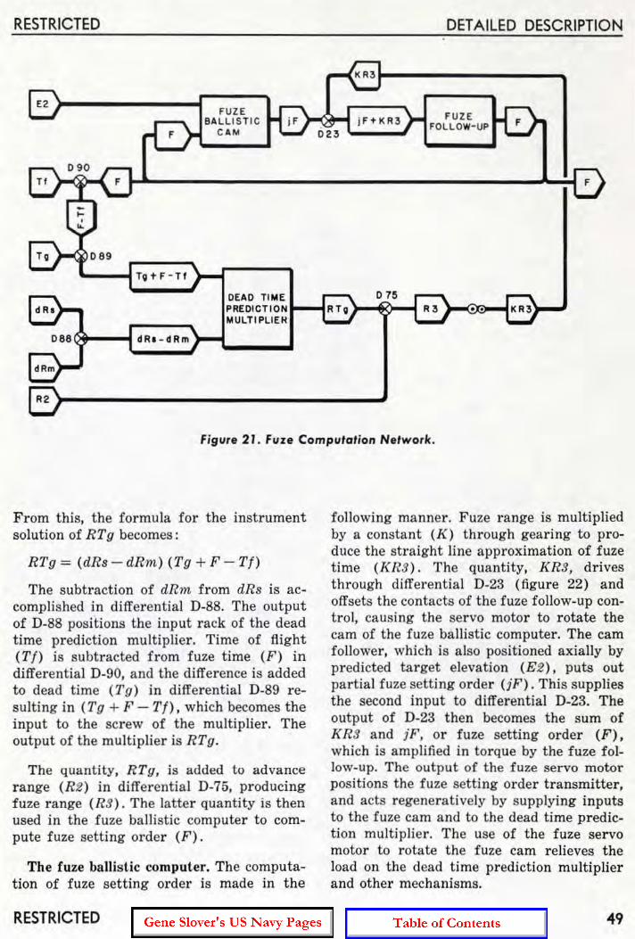
RESTRICTED
j F+KR3
DETAILED DESCRIPTION
FUZE FOLLOW-UP
FUZE BALLISTI C
CAM 023
TV't-F-Tt
DEAD TIME PREOIC TlON .... -I
~ ____ -(~~~~ __ ~.~U:LT~'~P~LI:E:JH D88~ dR. - dRm
Figure 2 J. fuze Computation Network.
From this, the formula for the instrument solution of RTg becomes :
RTg = (dRs - dRm) (Tg + F - Tf)
The subtraction of dRm from dRs is accomplished in differential D-88. The output of D-88 positions the input rack of the dead time prediction multiplier. Time of flight (Tf) is subtracted from fuze time (F) in differential D-90, and the difference is added to dead time (Tg) in differential D-89 resulting in (Tg + F - Tf), which becomes the input to the screw of the multiplier. The output of the multiplier is RTg.
The quantity. RTg, is added to advance range (R2 ) in differential D-75, producing fuze range (RS) . The latte r quantity is then used in the fuze ballistic computer to compute fuze setting order (F).
The fuze ballistic computer. The computation of fuze setting order is made in the
RESTRICTED
following manner. Fuze range is multiplied by a constant (K) through gearing to produce the straight line approximation of fuze time (KRS). The quantity, KRS, drives through differential D-23 (figure 22) and offsets the contacts of the fuze follow-up control, causing the servo motor to rotate the cam of the fuze ballistic computer. The cam follower, which is also positioned axially by predicted target elevation (E2). puts out partial fuze setting order (jF) . This supplies the second input to differential D-23. The output of D-23 then becomes the sum of KR3 and iF, or fuze setting order (F), which is amplified in torque by the fuze follow-up. The output of the fuze servo motor positions the fuze setting order transmitter, and acts regenerativeiy by supplying inputs to the fuze cam and to the dead time prediction multiplier . The use of the fuze servo motor to rotate t he fuze cam relieves the load on the dead time prediction multiplier and other mechanisms.
49

OP 10M-ADDENDUM No. I
Initial Velocity
The description given in OP 1064 (page 308) under the heading " Initial Velocity" is applicable to Computer Mk 1A if it is borne in mind that, wherever the value 2550 fs appears, it refers to the design I . V. of the instrument. Only Mods 8 and 12 have a design I . V . of 2550 fs. In applying the
RESTRICTED
description to other mods, the appropriate values should be substituted.
Mods 13, 14, 15, and 16 contain a supplementary initial velocity corr ection to TfJR2. It has already been described in this addendum under the heading, "The Elevation Pre~
diction Networ k."
SPOTS
The description under the heading SPOTS given ill OP 1064 (page 312) is applicable to the Computer Mk l Ao In the case of Mods 8 and 12, however , additional information is necessary since these mods are designed to permit fir ing at surface targets beyond the maximum value of the advance range limit stop by a system of elevation spots.
Elevation Spot for Surface Fire
Mods 8 and 12 compute superelevation in the same manner as other mods for values of advance range within the limits of 500 and 20,000 yards. Since 5"/ 54 cal. guns to which Mods 8 and 12 apply have extreme ranges exceeding 20,000 yards at low position angles (target elevation, E), it might be desired to fire at surface targets at these longer ranges. In such a case, computed s uperelevation will s top at the value corresponding to 20,000 yards advance range. The additional superelevation necessary is introduced as an UP elevation spot (Vj ). This acts to increase gun elevation order. To aid in computing the magnitude of spot required, a transparent di.al is superimposed on the elevation spot dia l. (See figure 8.) This dial is calibrated in yards range, from 20,000 to 24,600. In operation, the elevation spot knob is turned until the over lay dia l indicates the value of advance range, which, in such a
case, must be determined independently of the computer. Range graduations on the overlay dial a re spaced so t hat t he value of the spot input will equal the additional superelevation required above 20,000 yards. The 20,OOO-yard graduation is aligned directly over the zero graduation of the V j dial. Although the graduations for ranges greater than 23,500 overlay the DOWN graduations on the Vj dia l, they have no meaning unless they have been brought to the fixed index by application of an UP spot.
Gun Orders
The description on gun orders given in OP 1064 (page 324) is applicable to Computer Mk 1A. However, Computers Mk 1A Mods 14, 15, and 16 t ransmit values of gun train orde r information in addition to the quantities covered in OP 1064.
This Quantity is transmitted by a single, IO-degree per revolution, 7G synchro generator. The transmitter is equipped with a dial tha t has a single index mark engraved on it. The index, when matched against a fixed index, indicates the electrical zero position of the transmitter. Values of gun train orde r (B'gr) position the t ransmitter, which transmi ts these values to the multiple turret in· dicators.
THE SYNCHRONIZE ELEVATION GROUP
The description of the synchronize elevation group of Computer Mk I given in OP 1064 is applicable to Computer Mk 1A with the following addition.
50
The Elevation Transmitter
Computer Mk 1A (all mods) also transmits the value of target elevation (E ) . It is transmitted in two ways, by a synchro gen-
RESTRICTED

RESTRICTED
erator and by a potentiometer. The output of the potentiometer is used in conjunction with Radar Equipment Mk 25 Mod 2 for stabilizing a scope presentation on Radar Indicator Mk 22 Mod 0 with the display
DETAILED DESCRIPTION
selector in. the 6 E position. The synchro signal is available for later use in target practice analysis and for indication in Elevation Indicator Mk 6, in the director, if required.
PARALLAX
The description under the heading "PARALLAX" in OP 1064 is applicable to Computer Mk lA with the exceptions given below.
Computer Mk lA Mod 15 does not compute parallax in elevation due to a horizontal base (Pv). Instead, it computes another parallax quantity, parallax range, described below. With the omission of the Pv computation in Mod 15, a cosine output rack is not required in the parallax component solver and is therefore omitted.
Parallax Range
The Computer Mk lA Mod 15 computes parallax range. This is a factor in the computation of the parallax correction that must be applied to gun train order to correct gun train for the horizonta l base between the reference point and the gun. Since the train parallax computer provides Ph for the directors, another mechanism is needed to compute Ph for the guns. Such a mechanism is located at each gun. However, the Computer Mk lA aids the computation by supplying
I R 2 I R2 >-PARALLAX
RAN GE CO~PUTER
lE2tL} TRAIN -i Sec ( E 2 fl)}... PARALLA X
COMPUT ER
one factor, namely, parallax range, equal to
Bee (E~~ L) . Transmitted to the guns, this
quantity is then multiplied by sin B'or and the applicable constants to produce the required parallax correction.
In computing parallax range, the train parallax computer supplies sec (E2 + L), which is multiplied by 1/ R2 in the parallax range computer (see figure 22). The parallax range computer is a single-cam computing multiplier. The cam is positioned by advance range (R2) and computes 1/ R 2. The input rack is positioned by sec (E2 + L) supplied by the train parallax computer. The output of the parallax range computer is sec(E2 + L)
R2
Parallax range is transmitted to the guns by a single-speed transmitter. The transmitter dial is graduated in yards, from 1500 to infini ty. The space between graduations varies inversely with advance range; that is, as the range increases the space between graduations decreases (see figure 23 ). This
.. Sec( E2. L) r PARALL A X
R2 RAN GE
TRANSMITTER
,...-----,
~ , PARA LLAX \ RANGE I L _____ J
/ ELECTR ICAL
OUTPUT TO GUNS
Figure 22. Parall ax Range Network.
RESTRICTED 51
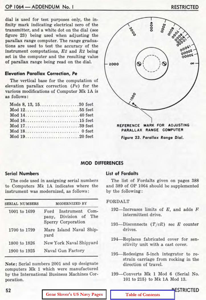
OP 10M - ADDENDUM No. I
dial is used for teSt purposes only, the infinity mark indicating electrical zero of the transmitter, and a white dot on the dial (see figure 23) being used when adjusting the parallax range computer. The range graduations are used to test the accuracy of the instrument computations, E2 and R2 being set in the computer and the resulting value of parallax range being read on the dial.
Elevation Parallax Correction, Pe
The vertical base for the computation of elevation parallax correction (Pe) for the various modifications of Computer Mk lA is as follows:
Mods 8, 13, 15 .... . . ............ 30 feet Mod 12 .... . .................... 55 feet Mod 14 .............. . ......... .40 feet Mod 16 ......................... 15 feet Mod 17 . . ........... . ...... . .... 39 feet Mod 18 .. . . . . .. . . . . . . . . . .. . . . . .. 0 feet Mod 19 . . ............ . .......... 20 feet
RESTRICTED
2000
o ~ ,
REfERE NCE MARK FOR ADJUSTING PARALLAX RANGE COMPUTER
Figure 23. Paralla x Range Dia l.
MOD DIFFERENCES
Se rial Numbers
The code used in assigning serial numbers to Computers Mk 1A indicates where the instrument was modernized, as follows:
SERlAL NUMBERS MODERNIZED BY
1001 to 1699 Ford Instrument Company. Division of The Sperry Cor poration
1700 to 1799 Mare Island Naval Shipyard
1800 to 1826 New York Naval Shipyard
1900 to 1925 Naval Gun Factory
Note: Serial numbers 2001 and up designate computers Mk 1 which were manufactured by the International Business Machines Cor~ poration.
52
List of Fordalts
The list of Fordalts given on pages 388 and 389 of OP 1064 should be supplemented by the following:
FORDALT
192- Increases limits of E, and adds F. intermittent drive.
193-Disconnects (Tj eR) sec E counter drives.
194-Replaces fabricated cover for sen· sitivity unit with a cast cover .
195- Redesigns 5·inch integrator to re· strain carriage from rocking in the direction of trave l.
199-Converts Mk 1 Mod 6 (Serial No. 101 to 215) to Mk 1A Mod 13.
RESTRICTED

RESTRICTED
200-Alters Ordalt 2331 into 2331A to provide adjustable smoothing of solution data for surface fire control.
201- Redesigns 5-inch integrator to strengthen ball retaining studs, and to provide finer adj ustment of horizontal rollers.
202-Redesigns 5-inch integrator to align integrator carriage correctly.
200-Converts two Computers Mk 1 Mod 8 and two Computers Mk 1 Mod 12 to Mk 1A Mod 17.
221-Converts Computer Mk 1 Mod 13 to Computer Mk 1A Mod 19.
List of Ordalts The list of Ordalts given on page 390 of
OP 1064 should be supplemented by the following:
ORDALT
2331A-Provides target vector rate control system (Mods 8, and 12 to 16).
2332- Increases limits of Sh, So, Sw, dH, dR, dRh, RdE, and RdBs (Mods 8, and '12 to 16).
2336- Provides for the transmission of E from both a potentiometer and a synchro generator (Mods 8, and 12 to 16).
2338-Changes, by replacement, I. V. dial under cover No.3 (Mods 0 to 7, 9, 10, and 13).
2339-Replaces ballistic cams to incorporate new 5"/38 cal. data as compiled in OP 551A (Mods 0 to 7 and 13).
2612- Alters Star Shell Computer Mk 1 Mod 2 by replacing 6DG synchro generators with 6G synchro generators.
2614-Provides for aleration of Mods 8, 13, and 14 instruments for use in AG128: On Mods 8 and 14, by replacement of dip dial and VI + Pe cam; on Mod 13, by replacement of dip dial and all ballistic cams.
RESTRICTED
DETAILED DESCRIPTION
2620-Installs micro-switch on l / cR cam to open rate control clutch circuits below 1500 yards (all mods),
2626--Incorporates operating control circuit changes which provide for:
1. Starting time motor automatically.
2. Automatically matching generated and observed range dials when range rate control switch is at AUTO.
3. Elimination of the requirement for an initial estimate of target motion (Mods 8, 12, 13, and 15),
2694- Provides Pe for vertical base of 55 feet and dip correction for 100 feet director height (six Mod 12 instruments only - two each on CVB 41, 42, and 43).
2894-Reduces oscillations in R2, E'g, and F (Mod 13 only).
2918-Removes limit stop L-36 (Mods 8, and 12 to 16),
2963-Same as Ordalt 2626 (for Mods 14 and 16 only).
3091-Changes time switch and removes target speed (Mods 8, and 12 to 16) .
Table of ModiAcation Differences Information concerning modification dif
ferences of Computer Mk 1A Mod 8, and Mod 12 through Mod 19 is given in tabular form on the following pages. This information corresponds to that given on pages 399 and 399A of OP 1064 for Computer Mk 1-
It should be noted here that Computer Mk 1A Mods 17 and 19 are for use in Gun Fire Control System Mk 67. They therefore differ from the other modification in more ways than can be indicated in the tabies. Reference should be made to OP 1064G Computer Mk 1A Mods 17 and 19 for further information on these modifications.
53

'" ....
;<J m V> ..... ;<J
~ m C
Moo NUMBER
Gun
Fe Base
Dip Base
Parallax Driven By
Star Shell Computer
Present Range
Advance Range (yd.)
Ta rget Height
Range Spot
Mech. Fuze (sec.)
Time of Flight (sec.)
Ship Speed
I. V. (it/ sec.)
8 12
5"/ 54 5"/ 54
30 ft. 55 ft .
22 yd . 13 yd.
Mkl Mkl Mod 2 Mod 2
500 500 20,000 20,000
0.60 0.60 49.00 49.00
0.60 0.60 50.60 50.60
2400 2400 2650 2650
TABLE OF MODIFICATION DIFFERENCES
MISCELLANEOUS
13 14 15 !6
5"/38 6"/47 8"/55 6"/ 47
30 ft. 40 ft. 30 ft. 15 ft.
17.83 yd. 70 ft. 59 ft . 45 ft.
Either by B' gr or B'r Selected by A-242
Mkl Mk! Mkl Mod 0 Mod 3 None Mod 3 or 1
LIMITS
0 35,000 yd.
500 500 500 500 18,000 20,200 20,000 20,200
0 50,000 ft.
IN 12,000 yd. OUT 1800 yd.
0.60 0.60 0.60 0.60 55.00 49.00 49.00 49.00
0.60 0.60 0.60 0.60 60.60 50.60 50.60 50.60
0 90kn .
2350 2250 2400 2250 2600 2720 2700 2720
17 18
5"/54 5"/ 54
39 ft. 0
Variable
Mkl Mkl Mod 4 Mod 2
500 500 20,000 20,000
0.60 0.60 49.00 49.00
0.60 0.60 50.60 50.60
2400 2400 2650 2650
19
5"/38
20 ft.
Variable
Mkl Mod 6
500 18,000
0.60 55.00
0.60 60.60
2350 2600
o ~
o <>.... I » c C m Z C C ~
Z o
;<J m ~ '" ~ m C

'" m ~ '" o --i m o
c.n c.n
11100 NUMBER
Elevation Spot(mils )
Elevation
Ds
Vs
oR
E
R2 (yd.)
So
R
L +Zd 30
Shaft
8
UP 342.5 DOWN
180
None
None
1500 18,900
TABLE OF MODIFICATION DIFFERENCES (Continued)
LI1I11TS (Con'inu.,l)
12 13 14 15 16
UP UP UP UP UP 342.5 180 180 180 180 DOWN DOWN DOWN DOWN DOWN
180 180 180 180 180
• - 25" +85"
INTER1I11TI'ENT DRIVES
None 320
None 390
None 680 590
None 2000
None 2000
None 3800 4460
750 yd. 22,500 yd.
- 2" + 85"
1500 None
1500 1500 1500 18,900 18,900 18,900 18,900
RECEIVERS
40.0 kn.
2000 yd. and 72,000 yd.
Provided
17 18
UP UP 342.5 342.5 DOWN DOWN
180 180
None None
None None
1500 1500 18,900 18,900
None Provo
19
UP 180
DOWN
180
None
None
None
None
'" m '" --i
'" o --i m o
o ~ » r m o o m
'" o '" ~ o z

TABLE OF MODIFICATION DIFFERENCES (Continuedl
TRANSlIlI'lTERS
MOD NUMBER 8 I 12 13 14 15 16
Train Parallax 7G's 30'
Elevation 7G Parallax
7G's 10' None 10'
Parallax None 7G None Range 0.001
7G's 6G's
7G's 7G's 7G's Sight 200' 2400' 200' 100' 200' Angle 200'
7200' 7200'
7200' 3600' 7200'
Sight De- 7G's 6G's 7G's 7G's
442.24 7G flection 100
100 100 210.48
100 (Mils) 4000
4000 4000 4000
Fuze 7G's 7G's 7G's
(sec. ) 2 20/ 7 2 100 360/ 7 100
Eleva-ticn &
6G's - 5 ' Auto. Bearing
5G's - 10' Ind. Correc-tion
B'gr Informa- None 7G's 10' ticD
17 18
5HG's 7G 10' 30'
360'
5HG's 7G 10' 10'
360'
None None
18CX4's 7G's I-speed 200'
36-speed 7200'
18CX4's 7G's I-speed 100
36-speed 4000
5HG's 7G's 72/ 7 2
360/ 7 100
6G's 5G's 5' 10' 5G's
10'
None None
19
5HG400 30'
None
None
5HG400's 200
7200
5HG400's 100
4000
5HG400's 2
100
5G's 10'
None
o "" o ~ I > o o m Z o C ~
z !>
'" m V> ..... '" g m o
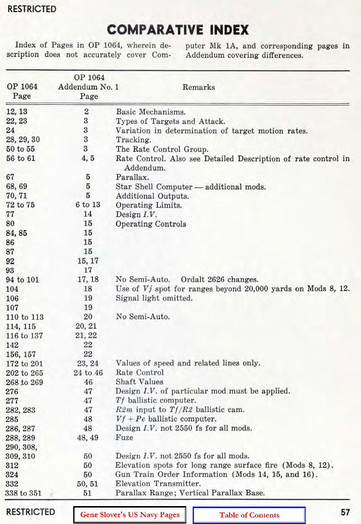
RESTRICTED
COMPARATIVE INDEX Index of Pages in OP 1064, wherein de
scription does not accurately cover Com-puter Mk lA, and corresponding pages in Addendum covering differences.
OP 1064 Page
12, 13 22,23 24 28,29,30 50 to 55 56 to 61
67 68,69 70,71 72 to 75 77 80 84, 85 86 87 92 93 94 to 101 104 106 107 110 to 113 114, 115 116 to 137 142 156, 157 172 to 201 202 to 265 268 .to 269 276 277 282,283 285 286,287 288,289 290, 308, 309,310 312 324 332 338 to 351
RESTRICTED
OP 1064 Addendum No.1
P age Remarks
2 3 3 3 3 4, 5
5 5 5
6 to 13 14 15 15 15 15
15,17 17
17,18 18 19 19 20
20,21 21,22
22 22
23,24 24 to 46
46 47 47 47 48 48
48,49
50 50 50
50, 51 51
Basic Mechanisms. Types of Targets and Attack. Variation in determination of target motion rates. Tracking. The Rate Control Group. Rate Control. Also see Detailed Description of rate control in
Addendum. Parallax. Star Shell Computer - additional mods. Additional Outputs. Operating Limits. Design I.V. Operating Controls
No Semi-Auto. Ordalt 2626 changes. Use of Vj spot for ranges beyond 20,000 yards on Mods 8, 12. Signal light omitted.
No Semi-Auto.
Values of speed and related lines only. Rate Control Shaft Values Design I. V. of particular mod must be applied. Tf ballistic computer. RZ". input to TI/ RZ ballistic cam. VI + Pe ballistic computer. Design I. V . not 2550 fs for all mods. Fuze
Design I . V. not 2550 fs for all mods. Elevation spots for long range surface fire (Mods 8, 12). Gun Train Order Information (Mods 14. 15, and 16), Elevation Transmitter. Parallax Range; Vertical Parallax Base.
57