
REITER GmbH + Co. KG Oberflächentechnik Telephone: +49 (0) 71 95 / 185 - 0Berglenstraße 23 - 25 Telefax: +49 (0) 71 95 / 185 - 30D-71364 Winnenden Internet: www.reiter-oft.de
Operating ManualElectrical Reciprocator EHR 8300-S (Ex) with Compact Guide Unit
Product No.: S-EHR8300-S-FFGB (Translation)Issue: 10/05 - 1

S-EHR8300-S-FFgbDB 10/05 - 1
Contents of the Operating Manual
Chapter 1 General
Chapter 2 Safety Regulations
Chapter 3 Technical Data
Chapter 4 Transport
Chapter 5 Function Description (not assigned)
Chapter 6 Installation (not assigned)
Chapter 7 Commissioning and Operation
Chapter 8 Maintenance
Chapter 9 Spare Parts
Chapter 10 Appendix (not assigned)

S-EHR8300-S-FFgb01 10/05 - 1 Page 1 of 2
1 General
1.1 IntroductionThis operating manual is intended to be read, understood and observed in all points by those re-sponsible for the installation. The same is valid for any personnel working at the installation.
This operating manual is intended to ensure trouble-free operation of the installation.
Should there be any problems please contact our service department or your local dealer which will be pleased to assist you (see chapter 9 “Spare parts“).
The operator is responsible for the correct installation, operation and maintenance of the equip-ment.
Should you intend to use the equipment in a manner different to the intended one please apply for our approval.The instruction manual must be completed with any local valid safety rules and environmental pro-tection laws.
The operating manual on hand only refers to the “Electrical Reciprocator EHR 8300-S (Ex) with Compact Guide Unit“.
We reserve the right to alterations in drawings and specifications necessary for the techni-cal improvement of the machine.
1.2 Operating AreaThis machine is built to be a part of a paint laboratory. It is designed for the movement of paint ap-plication equipment for test purposes.
Operation is only permitted within enclosed spray booths. Any other application is not according to its destination. For any damage caused by such a misuse the manufacturer can not be held liable! The risk therefore lies only with the user.
In case of doubts we recommend to contact REITER GmbH + Co. KG Oberflächentechnik.
Table of Contents
1.1 Introduction ........................................................................................................................11.2 Operating Area ...................................................................................................................11.3 Guarantee ..........................................................................................................................21.4 Copyright............................................................................................................................2

S-EHR8300-S-FFgb01 10/05 - 1 Page 2 of 2
1 General
1.3 GuaranteeTherefore, it is recommended to read this operating manual carefully before start-up, as we can-not be held liable for damage or malfunctions resulting from the non-observance of this operating manual.
During the guarantee period repair work and changes only may be carried out by our assemblers or with our consent.
The system is designed only for the use according to the operating area described in chapter 1.2 „Operating Area“.Any other use is considered improper and REITER can not be held liable for any possible damage.
1.4 CopyrightThe copyright for this operating manual is retained by REITER GmbH + Co. KG Oberflächentech-nik. This operating manual is intended for personnel involved in installation, operation and supervi-sion. The operating manual include regulations and technical drawings which may not be copied, distributed, used for commercial purpose or given to others, either in full or in part.
REITER GmbH + Co. KG Oberflächentechnik Telephone: +49 (0) 71 95 / 185 - 0Berglenstraße 23 - 25 Telefax: +49 (0) 71 95 / 185 - 30D-71364 Winnenden Email: [email protected]

S-EHR8300-S-FFgb02 10/05 - 1 Page 1 of 2
2 Safety Regulations
2.1 Explanation of symbols and special directions
2.1.1 Symbol of working safetyThis symbol accompanies all special directions for working safety given in this operating manual, the non-observance of which may en-danger life and limb. Observe these directions and take special care in these cases. Ensure all other operators are informed of these special directions. In addition to the special directions given in this operating manual, the generally valid regulations for safety and prevention of ac-cidents are also to be observed.
2.1.2 Directions for “Attention“This warning is given in this operating manual at points which are to be given special attention in order that guidelines, regulations, special directions and proper work procedures are observed, and to prevent damage or destruction of the machine and/or other parts of the plant.
2.2 Direction for working safetyThis machine can be hazardous if not used as described in the instruction manual.
We recommend to install a warning sign listing the important operating and safety rules. The sign should be in an understandable language for the operators and installed visible in the vicinity of the spray booth.
The following directions for working safety are to be given particular attention:
This machine has been constructed according to advanced technological standards and is opera-tionally reliable. Danger may, however, result from the machine if operated incorrectly by untrained persons or used for purposes other than those for which it was constructed.
!
Attention!
Table of Contents
2.1 Explanation of symbols and special directions ..................................................................12.1.1 Symbol of working safety ...................................................................................................12.1.2 Directions for “Attention“ ....................................................................................................12.2 Direction for working safety................................................................................................1

S-EHR8300-S-FFgb02 10/05 - 1 Page 2 of 2
2 Safety Regulations
• Itisnecessarythatallpersonsassignedwiththeinstallation,dismantlingandre-installation(inspection, maintenance, repairs) of the machine at the user’s plant, read and understand the entire operating instructions, and the chapter 2 „Safety Regulations“ in particular. The user is recommendedtohavethisconfirmedineachcaseinwriting.
• ThemachineisdesignedonlyfortheapplicationspecifiedinChapter1.2„OperationArea“.Anyusagenotcoveredinthesespecificationsisconsideredcontrarytoregulations.
• Themanufacturerisnotliablefordamageresultingfromimproperuse;theusercarriestheriskfor this alone.
• Properusealsoincludestheobservanceofprescribedconditionsforinstallation,dismantlingand re-installation, start-up procedures, operation and maintenance.
• Themachineistobeservicedandrepairedbyauthorised,trainedandinstructedpersonnelonly. This personnel must have been specially instructed regarding occurring risks.
• Responsibilityforinstallation,dismantlingandre-installation,start-upprocedures,operationandmaintenancemustbeclearlydefinedandobservedinordertopreventresponsibilitiesconcerning safety aspects from becoming unclear.
• Theswitch-offproceduresprovidedintheoperatinginstructionsaretobeobservedforallprocedures having to do with installation, dismantling and re-installation, start-up procedures, modification,adaptationandmaintenance.
• Anymannerofworkingwhichimpairstheoperatingsafetyofthemachineistobestopped.
• Theoperatorisalsotoensurethatnounauthorizedpersonsoperatethemachine.
• Unauthorizedmodificationsorchangeswhichimpairtheoperatingsafetyofthemachinearenot permitted.
• Allmaintenanceworkorrepairsonthemachinearetobecarriedoutonlywhenthemachineisnot in operation.
• Beforemaintenanceworkorrepairsarecarriedoutonthemachine,thedrivesandaccessoryparts of the machine are to be ensured against being switched on unintentionally.
• Beforestartingupafterrepairs,ensurethatallprotectiondevicesaremounted.Protectionde-vices are to be removed only when the machine is not in operation.
• Allsafetyprecautionsusedaretobetestedaftercorrespondingelectricalinstallationsorre-pairs (e.g. earthing resistance).
• Thelocallyvalidregulationsforsafetyandpreventionofaccidentsarevalidfortheoperationofthe machine under all circumstances.
• International,nationalandcompanysafetyregulationsaretobeobservedfortheinstallationand operation of the machine, as well as the procedures involved in maintenance, repairs and cleaning.

S-EHR8300-S-FFgb03 10/05 - 1 Page 1 of 1
3 Technical Data
Table of Contents
3.1 Technical Data ...................................................................................................................1
3.1 Technical DataStroke: max. 2.000 mm
Range of speed: 12 - 72 m/min
Drive: worm gear S050-HG-IEC-90 electrical motor with brake EEXDIICT4 230/400 V 1,5 kW
Path control: 2 pcs. mechanical limit switch 1 pcs. proximity switch 1 pcs. pulse generator
Load capacity: max. 15 kg

S-EHR8300-S-FFgb04 10/05 - 1 Page 1 of 1
4 Transport
Table of Contents
4.1 Packing ..............................................................................................................................14.2 Sensitivity ...........................................................................................................................14.3 Intermediate storage ..........................................................................................................14.4 Damage during transport ...................................................................................................1
4.1 Packing
Type of packing depends in part on the distance the machine is to be shipped. The machine is transported on square strips of timber without crate if not agreed otherwise. The designations and graphical symbols affixed to the machine are to be observed!
4.2 SensitivitySpecial care is required in transporting the machine in order to prevent damage due to extraneous forces or improper loading and unloading. Sufficient safety devices for transport are provided ac-cording to type and duration of transport.
The machine may be slung or lifted only at the designated places.
4.3 Intermediate storageIf the machine is not to be installed directly after delivery, it must be stored properly in a protected place. Ensure proper covering for storage.
4.4 Damage during transportPossible transport damage and/or missing parts are to be reported immediately in writing.
Attention!

S-EHR8300-S-FFgb07 10/05 - 1 Page 1 of 2
7 Commissioning and Operation
Table of Contents
7.1 General notes ....................................................................................................................17.2 Switching on the machine – Test run .................................................................................2
7.1 General notesPlease note before commissioning:
• Allgearshavebeenrunin,areprovidedwithmaximumoilfillingandcanberunimmediatelyatoperatingload.
• Checktheoillevelattheoil-levelplug/oil-levelgauge,dependingoninstallationposition.Theoil-levelplugisdesignatedin red.
• Exchangeattachedventscrewwithascrewplug,accordingtoinstallationpositionorremovecapstufffromventscrew.
Check before switching on:
• Whetherthesafetydevicesfortransporthavebeenremoved
• Functionofthestoppositionlimitswitches
• Smoothrunningofthemechanicalguideelements
• Noinhibitinginfluencesthroughdirectlyattachedconstructionsorotherassemblies
• Weightcounterbalancethroughcounterbalancecarriages

S-EHR8300-S-FFgb07 10/05 - 1 Page 2 of 2
7 Commissioning and Operation
7.2 Switching on the machine – Test run • Formulti-axesmachines,firsttesteachindividualaxle
• Startdriveswithspeedcontrolallowspeed
Thestoppositionswitch-offfunction!
• Theswitcheslimitthemax.possiblestroke!
• Whenoperatedthedrivemuststopimmediately!
• Thelimitswitchistobeadjustedinaposition,thatwhenoperatedatmax.speed,thecarriagestopsapprox.20mmbeforethemechanicalstop.
Attention!

S-EHR8300-S-FFgb08 10/05 - 1 Page 1 of 13
8 Maintenance
Table of Contents
8.1 Lubrication and maintenance of chain drives ....................................................................18.2 Overview of lubrication points ............................................................................................48.2.1 Lubrication points list .........................................................................................................58.3 Layout of drawings .............................................................................................................68.4 Ball boxes and rail guides ..................................................................................................78.4.1 Lubrication and maintenance .............................................................................................78.5 Lubrication and maintenance of the gear box ....................................................................88.6 Carriage guides..................................................................................................................98.6.1 Carriage guide and guide rails ...........................................................................................98.7 Chain tension ...................................................................................................................108.8 Checking and adjusting the reversing points ................................................................... 118.9 Loading or removing counterweights ...............................................................................128.10 Guiding rollers on the counterbalance carriage ...............................................................138.10.1 Exchanging the guiding rollers .........................................................................................13
8.1 Lubrication and maintenance of chain drivesIt is possible to use solid lubricants for the chain drives.
Solid lubricants are:
• Colloidalgraphite
• Finegraphiteforcoarsedrives
• Molybdenumsulphide(MoS2)
The use of a spray for the chains, no matter what kind, is not supported by REITER GmbH + Co. KGOberflächentechnik.REITERGmbH+Co.KGOberflächentechnikmustbeconsultedfirstbe-fore using a spray.
Manual Lubrication
The lubricant is applied between the inner and outer plates of the chain with an oilcan or on the in-side of the chain lustrum with a brush. A chain that is lubricated periodically should be cleaned with oil-anddirtdissolvingcleaningagentsfirstbeforelubrication.
A spray can is suited for manual lubrication on open chain drives. The lubrication can be done without having to disassemble the chain. With help of a small extension straw a well-aimed and economical application is possible. The spraying jet should be aimed between the inner and outer plates so that the lubricant can penetrate the chain links.

S-EHR8300-S-FFgb08 10/05 - 1 Page 2 of 13
8 Maintenance
Whengreasingthechainsitisrecommendedtolaytheminheated,liquefiedgrease.Thechainshould stay in the grease until it has reached the same temperature as the grease and air bubbles arenolongerrising.Thenthechainlinksarefilledsufficientlywithgrease.
The grease has to be heated in a container which is placed in warm water. Heating grease over an openflamewillleadtooverheatingofthegreaseandthelubricationabilitywillbedecreased.
Lubricating intervals are dependent on the conditions of operation and vary greatly. It is therefore difficulttospecifyanexactlubricatingschedule.
For operation in enamelling lines or similar, the lubricant may loose its lubricity relatively quickly due, for example, to the evaporation of solvents.
In any case, the operator must ensure that the lubricating intervals are short enough to ensure suf-ficientlubricationofthechaindrivesandtopreventdryrunning.
In addition to routine lubrication, the chain slack and the sprockets must be checked on a regular basis.
Withinthefirst3monthaftercommissioningofthesystemthechainslack must be checked once a week.
The slack of the return strand should not be greater than 2 % of the length of the return strand. Otherwise it needs to be tensioned.
Attention!

S-EHR8300-S-FFgb08 10/05 - 1 Page 3 of 13
8 Maintenance
To recognize when the chain needs to be replaced the chain manufacturers recommend the follow-ing method:
The wearing limit is established by compared measurements.
Thereforeancontrollengthof34increments(seespreadsheet)iscomparedwiththestretchedchain. If there are 33 or less increments within the control length, the chain must be replaced.
Oscillating chains must be measured at the area stressed by the reversing.
33 and less increments, replace chain
p x 34 increments = control length
Increments Original length p Control length (mm) at34increments(mm)
8 mm 8 272
3/8“ 9,525 323,9
1/2“ 12,7 431,8
5/8“ 15,875 539,8
3/4“ 19,05 647,7
1“ 25,4 863,6
S-EHR8300-S-FFgb08 10/05 - 1 Page 4 of 13
8 Maintenance
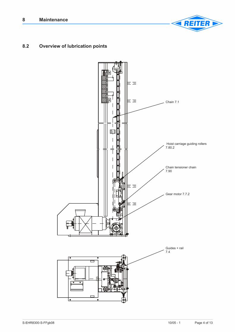
8.2 Overview of lubrication points
Chain 7.1
Hoist carriage guiding rollers 7.80.2
Chain tensioner chain 7.90
Gear motor 7.7.2
Guides + rail7.4

S-EHR8300-S-FFgb08 10/05 - 1 Page 5 of 13
8 Maintenance
8.2.1 Lubrication points listPosition No in No. of lubrication Description of Symbols of according to points lubrication points lubricant lubrication drawing
7.1 1 chain drives
7.4 2 ball boxes an rail guides
7.7.1 1 gear boxes
Legend
Mineraloil
Synthesisfluids
Lubricationgrease(mineraloilbase)

S-EHR8300-S-FFgb08 10/05 - 1 Page 6 of 13
8 Maintenance
8.3 Layout of drawings
Pulse generator 7.9.1
Junction box
Chain tensioner 7.90
Limit switch
Hoist carriage 7.80
Limit switch
Counterbalance carriage

S-EHR8300-S-FFgb08 10/05 - 1 Page 7 of 13
8 Maintenance
8.4 Ball boxes and rail guides
8.4.1 Lubrication and maintenanceThe usual regulations for roller bearings apply. Conventional roller bearing grease may be used; however, different brands should not be mixed.Lithium soap grease of consistency class NLGI2, DIN 51 818 may be used for roller bearing guides subject to normal wear.
Lubricate with a grease gun until lubricant is exuded.
Lubricating intervals are dependent on the conditions of operation and vary greatly. It is therefore difficulttospecifyanexactlubricatingschedule.
For operation in enamelling lines or similar, the lubricant may loose its lubricity relatively quickly due, for example, to the evaporation of solvents.In any case, the operator must ensure that the lubricating intervals are short enough to ensure suf-ficientlubricationofthebearings.
Ensure that the guide elements are kept clean and that mechanical damage does not occur.Attention!
Compact guide unit

S-EHR8300-S-FFgb08 10/05 - 1 Page 8 of 13
8 Maintenance
8.5 Lubrication and maintenance of the gear box
Check oil level and the oil-level plug according to installation position.
Allwormgearunitsandvariantsaswellasgearmotorsarefilledwithsyntheticlubricantatthefac-tory,unlessotherwiseindicatedintheconfirmationoforder.Ifagearunitisrequestedtobedeliv-ereddry,itshouldbefilledwithanoilqualityaccordingtothemarker’splate.
When using mineral oils, reduced performance should be taken into account. Please ask for advice about this.
Therecommendedlevelofoilisreachedwhenoildripsoutoftheoillevelscrew(size100to315).
For lubrication amounts refer to lubrication table.
The following mineral gearing lubricants are recommended by the manufacturer:
Oil quality acc to type label Vis- kosity in mm2/s.Lubricant (cSt)at40°C ARAL BP Esso Klüber Mobil Shell Texaco ICI/Tribol
Syntheticoils PG220 Degol BPEnergol Umlauföl Syntheso Mobil Trivela Tribol
(Polyglykole) 220 SG-XP220 S220 HT220 Glygoyl30 OilWB 800/220
We recommend using these or equivalent lubricants.
Attention!

S-EHR8300-S-FFgb08 10/05 - 1 Page 9 of 13
8 Maintenance
8.6 Carriage guidesThe carriage guides are adjusted ex works. Their function is guaranteed. To ensure reliability and function on the reciprocator it is necessary to check on a regular basis of 200 operating hours the following parts and adjustments:
• correctadjustmentoftheroller
• conditionsoftherollersandguiderails
• cleannessoftherollersandguiderails
8.6.1 Carriage guide and guide railsRollers at carriage.All rollers are tilled with an eccentric bolt and therefore adjustable.
Readjusting the rollersReleasethehexagonnut(SW24).Turntheboltbyitshexagonheadwithanopen-endwrenchuntiltheflatrollerisincontactwiththeguiderail. Thenlockfirmly
Thesettingiscorrectwhentheguidingrollersarefirmlygrippedbe-tweenthumbandfirstfingerandrotateontheguiderailwhilelockingnut its tight. Do not adjust to an excessively tight tension.
This will cause extensive wear of the rollers. Furthermore excessive tension will deform the carriage and this may lead to fatighe breack-age.
Attention!

S-EHR8300-S-FFgb08 10/05 - 1 Page 10 of 13
8 Maintenance
8.7 Chain tensionNecessary tools: 2 piece wrench 19
• Loosennut(1)
• Turnnut(2)untilchainistensioned
• Theslackofthereturnstrandshouldnotbegreaterthen2%ofthelengthofthereturnstrand
• Tightennut(1)again

S-EHR8300-S-FFgb08 10/05 - 1 Page 11 of 13
8 Maintenance
8.8 Checking and adjusting the reversing points
This adjustment is particularly important to prevent damage to the hoist.
It must be ensured that hoist reversal when maximum hoist is adjusted is always at least 30 to 40 mm in front of the hoist carriage stop.
The total weight of the hoisted mass at maximum speed produces the longest over-run path of the hoist carriage, measured from the electrical change-over point to the actual point of reversal of the carriage.
In most cases readjustment is required when the hoist is set into operation.For this purpose use the enclosed operating manual for the frequency converter and the path con-trol for the electric hoists.
Achtung!

S-EHR8300-S-FFgb08 10/05 - 1 Page 12 of 13
8 Maintenance
8.9 Loading or removing counterweights • Releasethelocknut(2).
• Turnthehexagonscrew(1)afewturnstotheleftuntilthepeg(3)canbedrawnoutattheback.
• Loadorremovethecounterweights(4).
• 2pinsorscrewdriversareusedasauxiliarytools;theyareinsertedintotheholes(5).
• Thepeg(3)isnotrequiredifthecounterbalancecarriageisentirelyfilledwithcounterweights.
• Thehexagonscrew(1)isscrewedintothecoverplate(6)togetherwiththelocknut,therebysecuring the counterweights.
Thecounterweightsmustbeverydefinitelysecured!
View without doors
5 holes for auxiliary tools
Peg
to s
ecur
e th
e ba
lanc
e w
eigh
tsLo
ad o
r rem
ove
the
bala
nce
wei
ghts
her
e

S-EHR8300-S-FFgb08 10/05 - 1 Page 13 of 13
8 Maintenance
8.10 Guiding rollers on the counterbalance carriageReadjustmentisunnecessaryhere(readjustedbypressurespring(38)).
Iftherangeofspringtravelbecomesinsufficient,orinthepresenceofconsiderablewear,itwillbenecessary to exchange the rollers.
8.10.1 Exchanging the guiding rollersTurnthelocknut(64)fullyinwards(torelievethespring).Exchangeallrollersandretension.
For initial tension see guiding rollers for hoist carriage.
Greasetheslot(under18).

S-EHR8300-S-FFgb09 10/05 - 1 Page 1 of 2
9 Spare Parts
9.1 GeneralA stock of the most important spare parts and parts subject to wear at the place of installation is an important prerequisite for the constant proper function and availability of the machine.
We provide a guarantee only for original spare parts delivered by us.
The specifications listed in the assembly drawings and parts lists provide further information. We provide a guarantee only for original spare parts delivered by us.
We expressly point out that original spare parts and accessories not delivered by us have also not been tested and approved by us. It is therefore possible that the installation and/or use of such products may negatively influence characteristics of the machine which are inherent in its construc-tion, thus impairing active and/or passive operating safety.
In case of damage resulting from the use of non-original spare parts and accessories, any liability or guarantee provided by REITER GmbH + Co. KG Oberflächentechnik is excluded.
The stock keeping of spare parts is provision for any the validity of agreements involving system availability, service times and guarantee or systems performance.
Please note that separate manufacturing and delivery specifications are often given for original and non-original parts, and that we offer spare parts constructed according to the latest technological developments and in compliance with legal regulations.
Table of Contents
9.1 General ..............................................................................................................................19.2 Spare parts order ...............................................................................................................2

S-EHR8300-S-FFgb09 10/05 - 1 Page 2 of 2
9 Spare Parts
9.2 Spare parts orderTo the order make use of the spare parts list in the part documentation and parts lists.
The pieces marked with “E“ in the part list are spare parts. The pieces marked with “V“ in the part list are wearing parts.
For the spare parts order the following data shall indicate:
• Order number (see acknowledgement)
• Part number (see part list)
• Designation (see part list)
• Parts lists designation
• No. of pieces


